
Proof of Concept of a New Revision Procedure for Ceramic Inlays of Acetabular Cups Using a Shape-Memory Alloy Actuator System

 , ,
, ,
Abstract
:
1. Introduction
2. Materials and Methods
2.1. Concepts for Fixing and Releasing Ceramic Inlays Using SMA Components
- (A)
- Using the conventional conical press connection of the components with new releasing mechanisms (Concepts 1–5).
- (B)
- Complete reconfiguration of the geometrical interface of cup and inlay to create a modified mechanical connection that can be used as an alternative or supplement to conical clamping (Concepts 6 and 7).
2.2. Clinical and Technical Requirements for the Final Implant and Actuator Design
- “Multicup II” metal cup made of a titanium–alumina–vanadium alloy (TiAl6V4 Grade 5) from Aristotech Industries GmbH, Luckenwalde, Germany,
- “ceramys” ceramic inlay from Mathys Orthopädie GmbH, Mörsdorf, Germany.
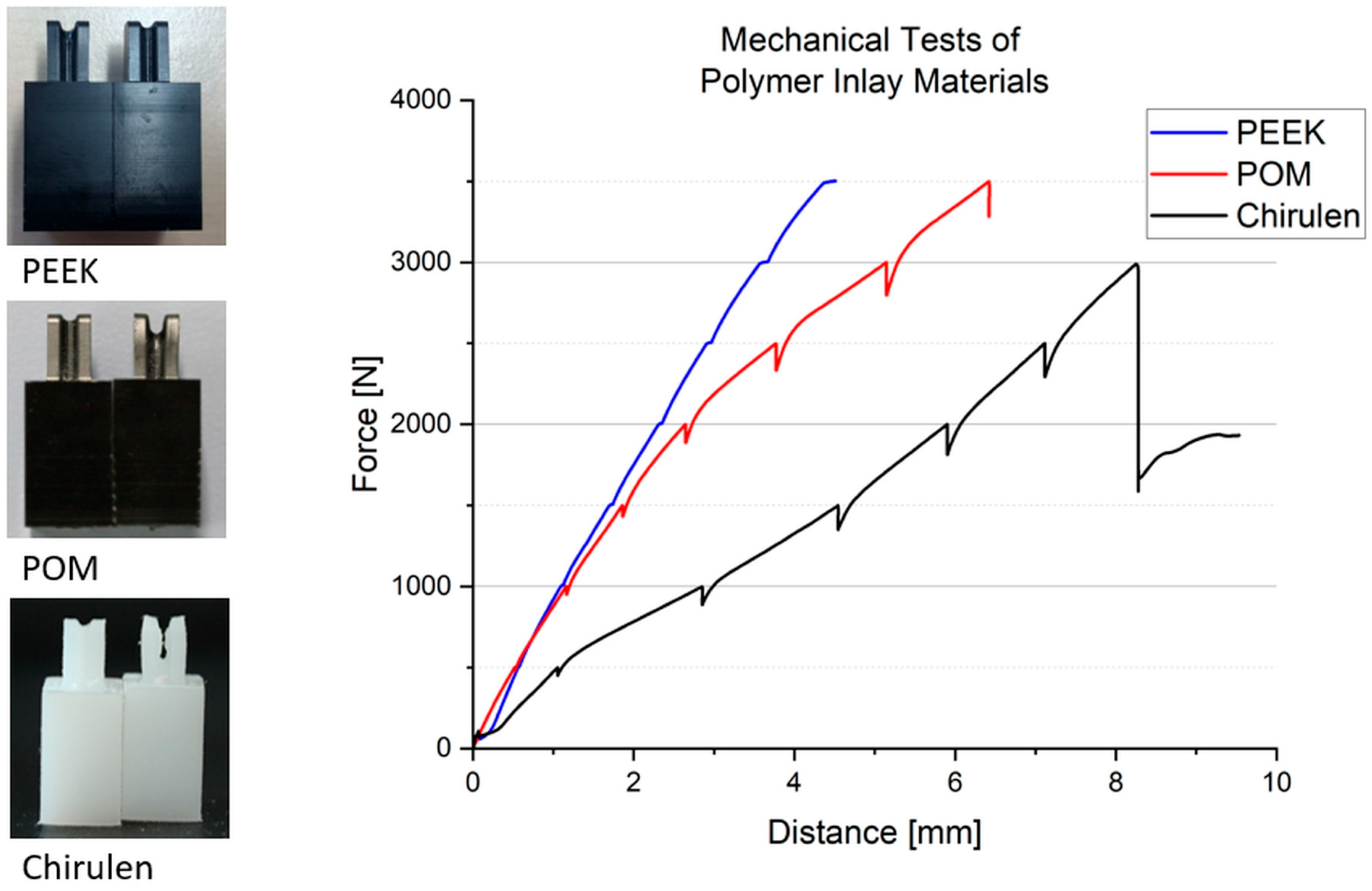
2.3. Inlay Components—Materials and Experimental Setup
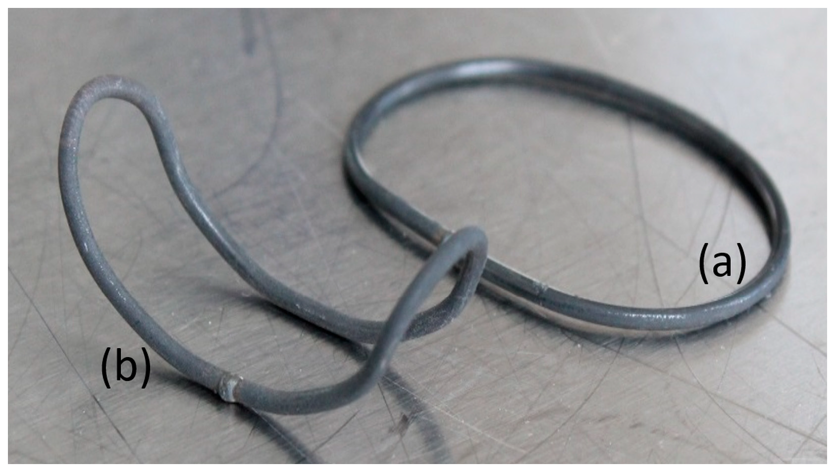
2.4. Shape-Memory Alloy Actuator—Manufacturing Process and Experimental Setup
- (1)
- Activation by placing the actuators in tempered water (70–80 °C) for up to 1 min as reference for complete phase transformation.
- (2)
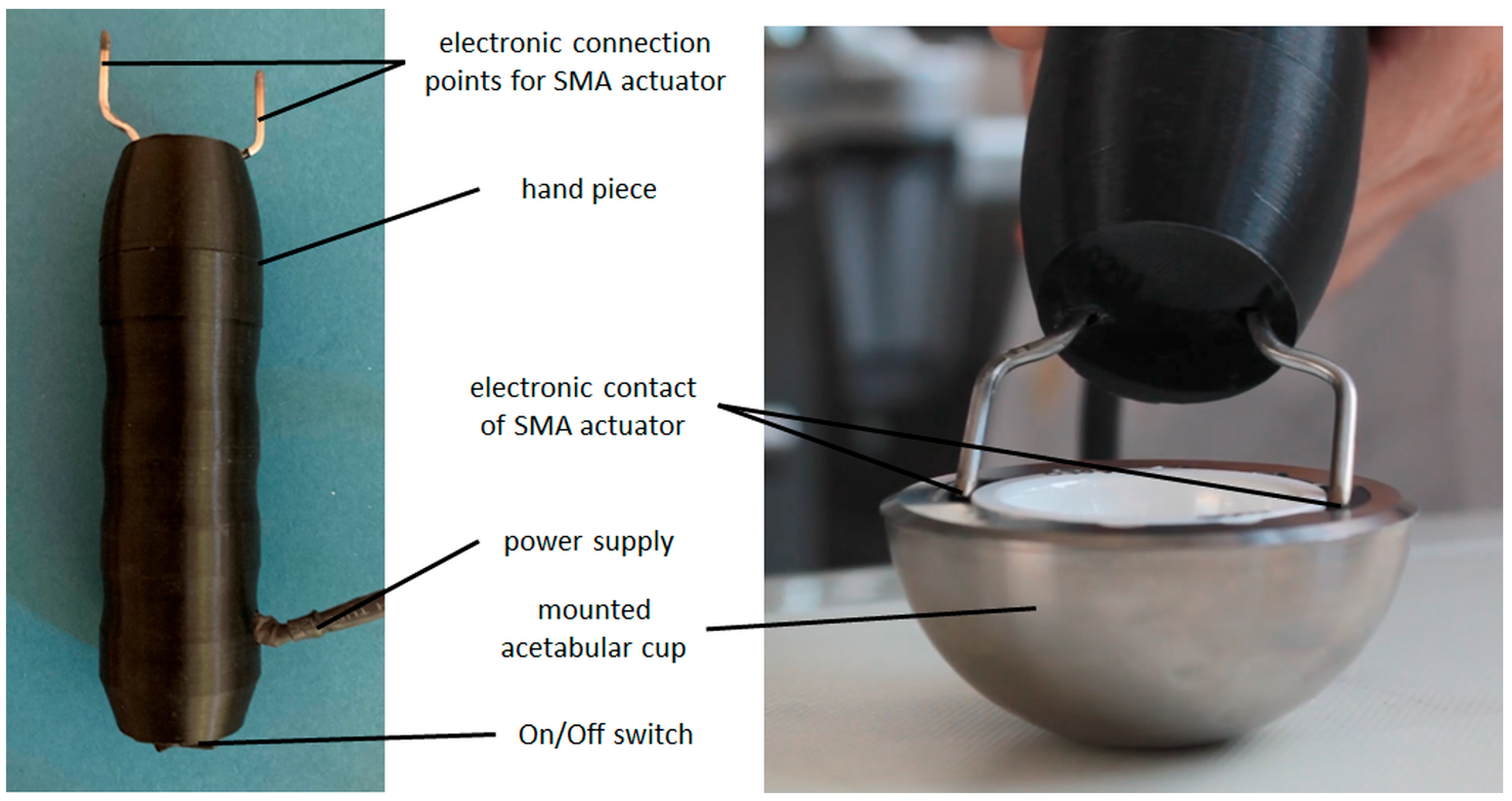
- Activation using electrical resistance heating by applying an activation instrument provided by endocon GmbH, Wiesenbach, Germany, to the mounted actuators (see Figure 7, right).
3. Results
3.1. Inlay Components—Experimental Results
3.2. Shape-Memory Alloy Actuator—Experimental Results
4. Discussion
4.1. Implant Design and Inlay Components
4.2. Shape-Memory Alloy Actuator
4.3. Revision Procedure
5. Conclusions
Author Contributions
Funding
Institutional Review Board Statement
Informed Consent Statement
Data Availability Statement
Acknowledgments
Conflicts of Interest
References
- El-Desouky, I.I.; Helal, A.H.; Mansour, A.M.R. Ten-year survival of ceramic-on-ceramic total hip arthroplasty in patients younger than 60 years: A systematic review and meta-analysis. J. Orthop. Surg. Res. 2021, 16, 679. [Google Scholar] [CrossRef]
- Vogel, D.; Kluess, D.; Bergschmidt, P.; Mittelmeier, W.; Bader, R. Ceramics for joint replacement. In Joint Replacement Technology; Elsevier: Amsterdam, The Netherlands, 2021; pp. 123–143. ISBN 9780128210826. [Google Scholar]
- Merfort, R.; Maffulli, N.; Hofmann, U.K.; Hildebrand, F.; Simeone, F.; Eschweiler, J.; Migliorini, F. Head, acetabular liner composition, and rate of revision and wear in total hip arthroplasty: A Bayesian network meta-analysis. Sci. Rep. 2023, 13, 20327. [Google Scholar] [CrossRef] [PubMed]
- de Fine, M.; Terrando, S.; Hintner, M.; Porporati, A.A.; Pignatti, G. Pushing Ceramic-on-Ceramic in the most extreme wear conditions: A hip simulator study. Orthop. Traumatol. Surg. Res. 2021, 107, 102643. [Google Scholar] [CrossRef] [PubMed]
- Whiting, F.; Lewis, C. A simple technique for ceramic liner extraction during revision total hip arthroplasty. Ann. R. Coll. Surg. Engl. 2014, 96, 549–550. [Google Scholar] [CrossRef] [PubMed]
- Pitto, R.P. Pearls: How to Remove a Ceramic Liner From a Well-fixed Acetabular Component. Clin. Orthop. Relat. Res. 2016, 474, 25–26. [Google Scholar] [CrossRef]
- Endocon GmbH. OrthoClast (R) Accessories—Efficient Removal of Ceramic Inlays: FR-063 Ceramic-Inlay Tappet. Available online: https://www.endocon.de/orthoclast-system.html (accessed on 13 June 2024).
- Gurung, B.; Shah, O.A.; Edwards, T.C.; Afzal, I.; Gikas, P.D.; Field, R.E. A Simple Technique to Remove an Incarcerated Ceramic Liner in Revision Hip Arthroplasty. Arthroplast. Today 2023, 21, 101142. [Google Scholar] [CrossRef] [PubMed]
- Bergmann, G.; Bender, A.; Dymke, J.; Duda, G.; Damm, P. Standardized Loads Acting in Hip Implants. PLoS ONE 2016, 11, e0155612. [Google Scholar] [CrossRef]
- Ruther, C.; Ewald, H.; Mittelmeier, W.; Fritsche, A.; Bader, R.; Kluess, D. A novel sensor concept for optimization of loosening diagnostics in total hip replacement. J. Biomech. Eng. 2011, 133, 104503. [Google Scholar] [CrossRef]
- Töppel, T.; Lausch, H.; Brand, M.; Hensel, E.; Arnold, M.; Rotsch, C. Structural Integration of Sensors/Actuators by Laser Beam Melting for Tailored Smart Components. JOM 2018, 70, 321–327. [Google Scholar] [CrossRef]
- Higa, M.; Tsuchihashi, T.; Abo, M.; Kakunai, S. Possibility of Total Hip Arthroplasty Using Shape Memory Alloy. JBSE 2010, 5, 24–31. [Google Scholar] [CrossRef]
- Langbein, S.; Czechowicz, A. Konstruktionspraxis Formgedächtnistechnik; Springer Fachmedien Wiesbaden: Wiesbaden, Germany, 2013; ISBN 978-3-8348-1957-4. [Google Scholar]
- Kumar, P.K.; Lagoudas, D.C. Introduction to Shape Memory Alloys. In Shape Memory Alloys; Springer: Boston, MA, USA, 2008; pp. 1–51. ISBN 978-0-387-47684-1. [Google Scholar]
- Drossel, W.G.; Pagel, K. Actuator. In CIRP Encyclopedia of Production Engineering; The International Academy for Production Engineering, Laperrière, L., Reinhart, G., Eds.; Springer: Berlin/Heidelberg, Germany, 2018; pp. 1–18. ISBN 978-3-642-35950-7. [Google Scholar]
- Mohd Jani, J.; Leary, M.; Subic, A.; Gibson, M.A. A review of shape memory alloy research, applications and opportunities. Mater. Des. 2014, 56, 1078–1113. [Google Scholar] [CrossRef]
- Goryczka, T.; Szponder, T.; Dudek, K.; Wierzchoń, T.; Paluch, J.; Jasik, K.; Wiaderkiewicz, R. NiTi Shape Memory Clamps with Modified Surface for Bone Fracture Treatment. Materials 2023, 16, 5575. [Google Scholar] [CrossRef]
- Alipour, S.; Taromian, F.; Ghomi, E.R.; Zare, M.; Singh, S.; Ramakrishna, S. Nitinol: From historical milestones to functional properties and biomedical applications. Proc. Inst. Mech. Eng. H 2022, 236, 1595–1612. [Google Scholar] [CrossRef] [PubMed]
- Reynaerts, D.; van Brussel, H. Design aspects of shape memory actuators. Mechatronics 1998, 8, 635–656. [Google Scholar] [CrossRef]
- Finazzi, V.; Berti, F.; Petrini, L.; Previtali, B.; Demir, A.G. Additive manufacturing and post-processing of superelastic NiTi micro struts as building blocks for cardiovascular stents. Addit. Manuf. 2023, 70, 103561. [Google Scholar] [CrossRef]
- Safaei, K.; Abedi, H.; Nematollahi, M.; Kordizadeh, F.; Dabbaghi, H.; Bayati, P.; Javanbakht, R.; Jahadakbar, A.; Elahinia, M.; Poorganji, B. Additive Manufacturing of NiTi Shape Memory Alloy for Biomedical Applications: Review of the LPBF Process Ecosystem. JOM 2021, 73, 3771–3786. [Google Scholar] [CrossRef]
- Kubášová, K.; Drátovská, V.; Losertová, M.; Salvetr, P.; Kopelent, M.; Kořínek, F.; Havlas, V.; Džugan, J.; Daniel, M. A Review on Additive Manufacturing Methods for NiTi Shape Memory Alloy Production. Materials 2024, 17, 1248. [Google Scholar] [CrossRef]
- Fumagalli, L.; Butera, F.; Coda, A. SmartFlex® NiTi Wires for Shape Memory Actuators. J. Mater. Eng. Perform. 2009, 18, 691–695. [Google Scholar] [CrossRef]
- Sabbagh, H.; Janjic Rankovic, M.; Martin, D.; Mertmann, M.; Hötzel, L.; Wichelhaus, A. Load Deflection Characteristics of Orthodontic Gummetal® Wires in Comparison with Nickel-Titanium Wires: An In Vitro Study. Materials 2024, 17, 533. [Google Scholar] [CrossRef]
- Mwangi, J.W.; Nguyen, L.T.; Bui, V.D.; Berger, T.; Zeidler, H.; Schubert, A. Nitinol manufacturing and micromachining: A review of processes and their suitability in processing medical-grade nitinol. J. Manuf. Process. 2019, 38, 355–369. [Google Scholar] [CrossRef]
- Oliveira, J.P.; Miranda, R.M.; Braz Fernandes, F.M. Welding and Joining of NiTi Shape Memory Alloys: A Review. Prog. Mater. Sci. 2017, 88, 412–466. [Google Scholar] [CrossRef]
- Parimanik, S.R.; Mahapatra, T.R.; Mishra, D. A Systematic Literature Review on Laser Welding of NiTi SMA. Lasers Manuf. Mater. Process. 2023, 10, 77–117. [Google Scholar] [CrossRef]
- Sevilla, P.; Martorell, F.; Libenson, C.; Planell, J.A.; Gil, F.J. Laser welding of NiTi orthodontic archwires for selective force application. J. Mater. Sci. Mater. Med. 2008, 19, 525–529. [Google Scholar] [CrossRef] [PubMed]
- Zeng, Z.; Yang, M.; Oliveira, J.P.; Song, D.; Peng, B. Laser welding of NiTi shape memory alloy wires and tubes for multi-functional design applications. Smart Mater. Struct. 2016, 25, 85001. [Google Scholar] [CrossRef]
- Mehrpouya, M.; Gisario, A.; Elahinia, M. Laser welding of NiTi shape memory alloy: A review. J. Manuf. Process. 2018, 31, 162–186. [Google Scholar] [CrossRef]
- Chan, W.-S.; Gulati, K.; Peters, O.A. Advancing Nitinol: From heat treatment to surface functionalization for nickel-titanium (NiTi) instruments in endodontics. Bioact. Mater. 2023, 22, 91–111. [Google Scholar] [CrossRef]
- Monu, M.C.; Kumar, S.S.; Brabazon, D. Heat treatment of NiTi alloys: Influence of volumetric energy density on ageing parameters and the resulting physical properties. J. Mater. Res. Technol. 2023, 26, 9532–9555. [Google Scholar] [CrossRef]
- Zupanc, J.; Vahdat-Pajouh, N.; Schäfer, E. New thermomechanically treated NiTi alloys—A review. Int. Endod. J. 2018, 51, 1088–1103. [Google Scholar] [CrossRef] [PubMed]
- Navickaitė, K.; Nestler, K.; Penzel, M.; Böttger-Hiller, F.; Zeidler, H. Preliminary experimental study on simultaneous polishing and shape setting of Nitinol wire. SN Appl. Sci. 2023, 5, 258. [Google Scholar] [CrossRef]
- Yip, M.C.; Alaie, S.; Romito, E.A.; Doshi, T.; Amiri Moghadam, A.A.; Mosadegh, B.; Dunham, S. Low-Cost and Rapid Shaping of Nitinol for Medical Device Prototyping. ASME Open J. Eng. 2023, 2, 021027. [Google Scholar] [CrossRef]
- Al-Shalawi, F.D.; Mohamed Ariff, A.H.; Jung, D.-W.; Mohd Ariffin, M.K.A.; Seng Kim, C.L.; Brabazon, D.; Al-Osaimi, M.O. Biomaterials as Implants in the Orthopedic Field for Regenerative Medicine: Metal versus Synthetic Polymers. Polymers 2023, 15, 2601. [Google Scholar] [CrossRef]
- Schierz, O.; Schmohl, L.; Hahnel, S.; Rauch, A. Polyoxymethylene as Material for Removable Partial Dentures-A Literature Review and Illustrating Case Report. J. Clin. Med. 2021, 10, 1458. [Google Scholar] [CrossRef]
- Kroczek, K.; Turek, P.; Mazur, D.; Szczygielski, J.; Filip, D.; Brodowski, R.; Balawender, K.; Przeszłowski, Ł.; Lewandowski, B.; Orkisz, S.; et al. Characterisation of Selected Materials in Medical Applications. Polymers 2022, 14, 1526. [Google Scholar] [CrossRef] [PubMed]
- Hussain, M.; Naqvi, R.A.; Abbas, N.; Khan, S.M.; Nawaz, S.; Hussain, A.; Zahra, N.; Khalid, M.W. Ultra-High-Molecular-Weight-Polyethylene (UHMWPE) as a Promising Polymer Material for Biomedical Applications: A Concise Review. Polymers 2020, 12, 323. [Google Scholar] [CrossRef]
- ASTM F 1820-22; Standard Test Method for Determining the Forces for Disassembly of Modular Acetabular Devices. American Society for Testing and Materials: West Conshohocken, PA, USA, 2022.
- Rotsch, C.; Kemter-Esser, K.; Dohndorf, J.; Knothe, M.; Drossel, W.-G.; Heyde, C.-E. Feasibility of a Shape-Memory-Alloy-Actuator System for Modular Acetabular Cups. Bioengineering 2024, 11, 75. [Google Scholar] [CrossRef] [PubMed]
- Ma, H.; Suonan, A.; Zhou, J.; Yuan, Q.; Liu, L.; Zhao, X.; Lou, X.; Yang, C.; Li, D.; Zhang, Y. PEEK (Polyether-ether-ketone) and its composite materials in orthopedic implantation. Arab. J. Chem. 2021, 14, 102977. [Google Scholar] [CrossRef]
- Bergmann, G.; Graichen, F.; Rohlmann, A.; Bender, A.; Heinlein, B.; Duda, G.N.; Heller, M.O.; Morlock, M.M. Realistic loads for testing hip implants. Biomed. Mater. Eng. 2010, 20, 65–75. [Google Scholar] [CrossRef] [PubMed]
- Nespoli, A.; Besseghini, S. A complete thermo-mechanical study of a NiTiCu shape memory alloy wire. J. Therm. Anal. Calorim. 2011, 103, 821–826. [Google Scholar] [CrossRef]
- Kök, M.; Al-Jaf, A.O.A.; Çirak, Z.D.; Qader, I.N.; Özen, E. Effects of heat treatment temperatures on phase transformation, thermodynamical parameters, crystal microstructure, and electrical resistivity of NiTiV shape memory alloy. J. Therm. Anal. Calorim. 2020, 139, 3405–3413. [Google Scholar] [CrossRef]
- Gao, S.; Bodunde, O.P.; Qin, M.; Liao, W.-H.; Guo, P. Microstructure and phase transformation of nickel-titanium shape memory alloy fabricated by directed energy deposition with in-situ heat treatment. J. Alloys Compd. 2022, 898, 162896. [Google Scholar] [CrossRef]
- Goergen, Y.; Rizzello, G.; Motzki, P. Systematic Methodology for an Optimized Design of Shape Memory Alloy-Driven Continuum Robots. Adv. Eng. Mater. 2024, 26, 2301502. [Google Scholar] [CrossRef]
- El-Kashef, T. Evaluation von Aspekten der thermischen Induktion einer implantierten Form-Gedächtnis-Legierung im Kleintiermodell. Ph.D. Thesis, University of Veterinary Medicine Hannover, Hannover, Germany, 2015. [Google Scholar]
- Wever, D.J.; Elstrodt, J.A.; Veldhuizen, A.G.; v Horn, J.R. Scoliosis correction with shape-memory metal: Results of an experimental study. Eur. Spine J. 2002, 11, 100–106. [Google Scholar] [CrossRef] [PubMed]
- Pospischill, M.; Knahr, K. Strategies for head and inlay exchange in revision hip arthroplasty. Int. Orthop. 2011, 35, 261–265. [Google Scholar] [CrossRef]
- Bhimani, A.A.; Rizkalla, J.M.; Kitziger, K.J.; Peters, P.C.; Schubert, R.D.; Gladnick, B.P. Surgical automation reduces operating time while maintaining accuracy for direct anterior total hip arthroplasty. J. Orthop. 2020, 22, 68–72. [Google Scholar] [CrossRef] [PubMed]
- Niki, Y.; Huber, G.; Behzadi, K.; Morlock, M.M. Vibratory insertion of press-fit acetabular components requires less force than a single blow technique. Bone Jt. Res. 2024, 13, 272–278. [Google Scholar] [CrossRef] [PubMed]
- Hunger, S.; Seidler, A.; Rotsch, C.; Heyde, C.-E.; Drossel, W.-G. Evaluating the Feasibility and Reproducibility of a Novel Insertion Method for Modular Acetabular Ceramic Liners. Bioengineering 2023, 10, 1180. [Google Scholar] [CrossRef]
- Dhotare, S.; Shah, N. Acetabular Component Extraction in Revision Hip Surgery. In Hip Arthroplasty; Sharma, M., Ed.; Springer Nature: Singapore, 2023; pp. 547–558. ISBN 978-981-99-5516-9. [Google Scholar]


| Concept Number/Category | Sketch—Sectional View | Description | Interface; Release Mechanism |
|---|---|---|---|
| 1/(A) |  | preloaded pseudoelastic SMA clamps restrained by thermally activated SMA wires; by cooling the SMA wires, the clamps are released and push out the ceramic inlay | pressfit, conical clamping; actuators must be cooled to release mechanism |
| 2/(A) |  | thermally activated SMA wires contracted by applying thermal energy causing them to move a ring and push out the inlay | pressfit, conical clamping; additional heat energy must be applied to release the mechanism |
| 3/(A) |  | thermally activated SMA wires contracted by applying thermal energy and directly pulling out the ceramic inlay | pressfit, conical clamping; additional heat energy must be applied to release the mechanism |
| 4/(A) | 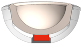 | thermally activated SMA element pushes out the inlay due to heating by thermal energy | pressfit, conical clamping; additional heat energy must be applied to release the mechanism |
| 5/(A) |  | preloaded super-elastic spring element pushes out the inlay by releasing screws | pressfit, conical clamping; additional tool required for releasing the screws |
| 6/(B) | 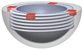 | threaded inlay is blocked by thermally activated SMA elements; by cooling and removing the SMA elements, the inlay can be unscrewed from the cup | screw connection replaces conical clamping; actuators must be cooled to unblock connection |
| 7/(B) | 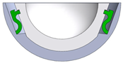 | super-elastic SMA clamps lock into a recess position and fixate the inlay | pseudoelastic SMA element replaces conical clamping; additional tool required to remove SMA clamps |
| Concept Number/Category | Geometry 1 | Surgical Procedure 2 | Actuator 3 | Fail Safe 4 | Points |
|---|---|---|---|---|---|
| 1/(A) | 0 | 1 | 2 | 1 | 4 |
| 2/(A) | 0 | 1 | 2 | 1 | 4 |
| 3/(A) | 2 | 2 | 2 | 1 | 7 |
| 4/(A) | 2 | 2 | 1 | 1 | 6 |
| 5/(A) | 1 | 1 | 1 | 0 | 3 |
| 6/(B) | 0 | 0 | 1 | 0 | 1 |
| 7/(B) | 0 | 0 | 2 | 0 | 2 |
| Parameter | |
|---|---|
| pushout force actuator | 6000 N |
| wire diameter | 1.95–2.05 mm |
| wire length | 50–140 mm |
| actuator tension | 200–800 MPa |
| actuator strain | 3–8% |
| actuator force | 630–2500 N |
| Material | Product Name, Manufacturer | Young’s Modulus (Tension) * |
|---|---|---|
| polyoxymethylene (POM) | TECAFORM AH black, Ensinger GmbH, Nufringen, Germany | 2800 MPa |
| chirulen/ultra-high molecular weight polyethylene (UHMW-PE) | CHIRULEN® 1050, Quadrant PHS Deutschland GmbH, Vreden, Germany | approx. 700 MPa |
| polyether ether ketone (PEEK) | TECAPEEK MT black, Ensinger GmbH, Nufringen, Germany | 4200 MPa |
| Incision Depth of PEEK Sample [mm] | |
|---|---|
| Sample | |
| 1 | 0.3 |
| 2 | 0.2 |
| 3 | 0.7 |
| 4 | 0.5 |
| 5 | 0.4 |
| 6 | 0.3 |
| mean value | 0.4 |
| standard deviation | 0.2 |
| Probe * | Condition | Length [mm] | Strain ** [%] |
|---|---|---|---|
| 130_1 | pre-stretched | 138.83 | 3.4 |
| current-activated | 134.42 | 0.1 | |
| pre-stretched | 138.56 | 3.2 | |
| water-activated | 134.24 | - | |
| 130_4 | pre-stretched | 139.39 | 4.3 |
| current-activated | 134.25 | 0.4 | |
| pre-stretched | 139.22 | 4.2 | |
| water-activated | 133.67 | - | |
| 132_5 | pre-stretched | 140.84 | 3.7 |
| water-activated | 135.85 | - | |
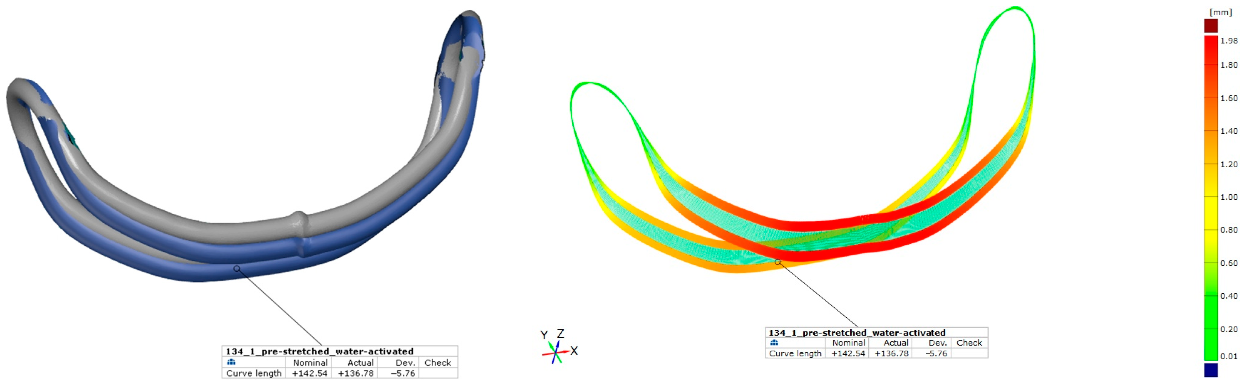
| 134_1 | pre-stretched | 142.54 | 4.2 |
| water-activated | 136.78 | - |
Disclaimer/Publisher’s Note: The statements, opinions and data contained in all publications are solely those of the individual author(s) and contributor(s) and not of MDPI and/or the editor(s). MDPI and/or the editor(s) disclaim responsibility for any injury to people or property resulting from any ideas, methods, instructions or products referred to in the content. |
© 2024 by the authors. Licensee MDPI, Basel, Switzerland. This article is an open access article distributed under the terms and conditions of the Creative Commons Attribution (CC BY) license (https://creativecommons.org/licenses/by/4.0/).
Share and Cite
Rotsch, C.; Kemter-Esser, K.; Dohndorf, J.; Funke, K.; Heyde, C.-E.; Drossel, W.-G. Proof of Concept of a New Revision Procedure for Ceramic Inlays of Acetabular Cups Using a Shape-Memory Alloy Actuator System. Bioengineering 2024, 11, 868. https://doi.org/10.3390/bioengineering11090868
Rotsch C, Kemter-Esser K, Dohndorf J, Funke K, Heyde C-E, Drossel W-G. Proof of Concept of a New Revision Procedure for Ceramic Inlays of Acetabular Cups Using a Shape-Memory Alloy Actuator System. Bioengineering. 2024; 11(9):868. https://doi.org/10.3390/bioengineering11090868
Chicago/Turabian StyleRotsch, Christian, Karoline Kemter-Esser, Johanna Dohndorf, Kerstin Funke, Christoph-Eckhard Heyde, and Welf-Guntram Drossel. 2024. "Proof of Concept of a New Revision Procedure for Ceramic Inlays of Acetabular Cups Using a Shape-Memory Alloy Actuator System" Bioengineering 11, no. 9: 868. https://doi.org/10.3390/bioengineering11090868
APA StyleRotsch, C., Kemter-Esser, K., Dohndorf, J., Funke, K., Heyde, C.-E., & Drossel, W.-G. (2024). Proof of Concept of a New Revision Procedure for Ceramic Inlays of Acetabular Cups Using a Shape-Memory Alloy Actuator System. Bioengineering, 11(9), 868. https://doi.org/10.3390/bioengineering11090868