The authors would like to make the following corrections to this paper [
1]:
Figure 1 and
Figure 3 should be replaced with the final versions, which were modified according to reviewer’s suggestions.
The correct versions are shown below.
Figure 1.
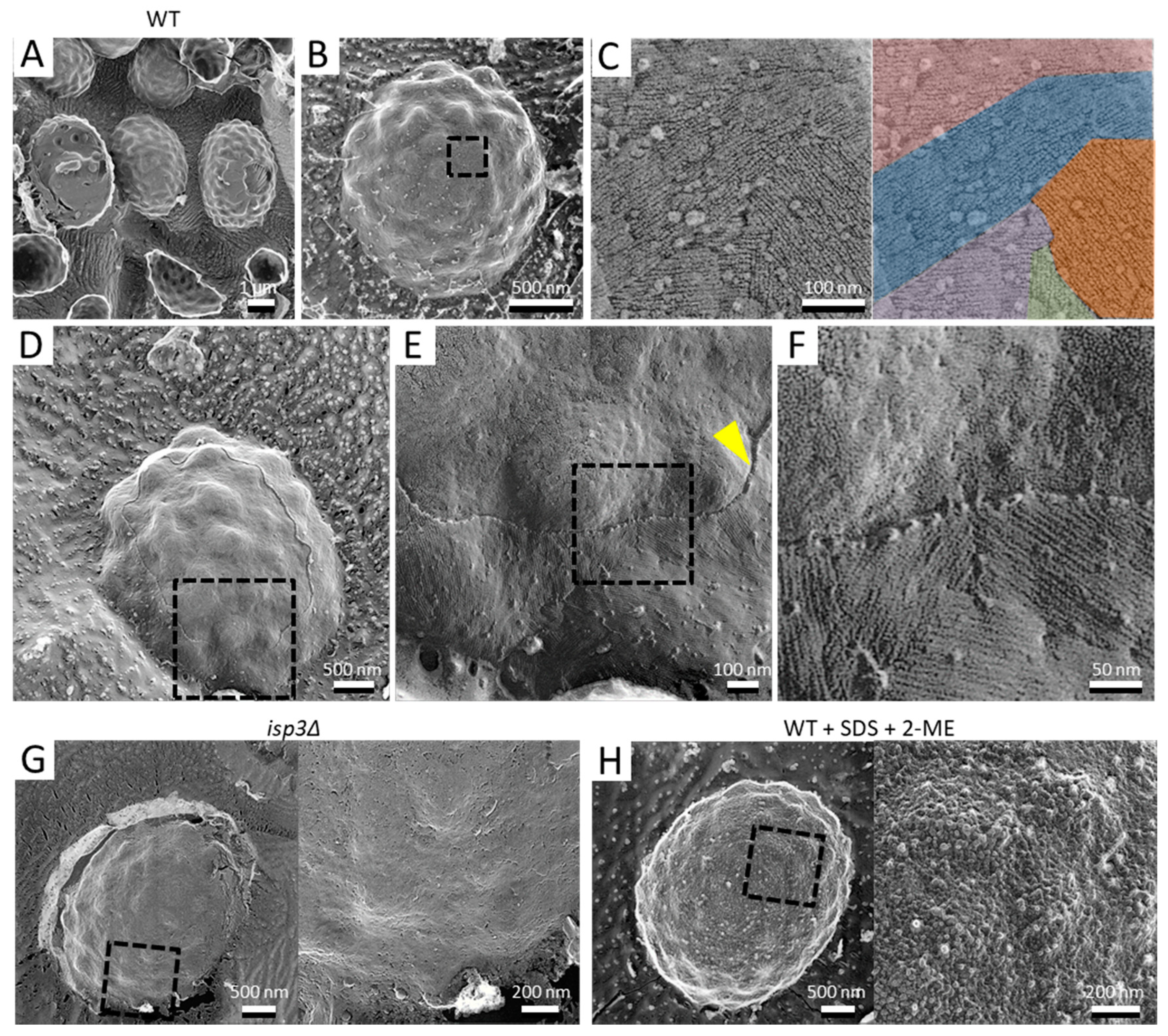
Surface structure of the S. pombe spore. (A) Field image of wild-type spores. Left spore shows a cytoplasmic cross-section. Center spore shows partial detachment of the surface layer. Right spore shows partial detachment of the spore wall. (B) Single spore. (C) Left, Magnified image of the boxed region in B. Right, the fibrillar structures are shown in various colors. (D) Spore with the outermost layer partly removed by fracture. (E) Magnified image of the boxed region in (D). Arrowhead indicates a cross-section of the fractured surface layer. (F) Magnified image of the boxed region in (E). (G) Left, isp3Δ spore. Right, magnified image of the boxed region. (H) Left, wild-type spore pretreated with 1% SDS and 5% β-mercaptoethanol (2-ME). Right, magnified image of the boxed region.
Figure 1.
Surface structure of the S. pombe spore. (A) Field image of wild-type spores. Left spore shows a cytoplasmic cross-section. Center spore shows partial detachment of the surface layer. Right spore shows partial detachment of the spore wall. (B) Single spore. (C) Left, Magnified image of the boxed region in B. Right, the fibrillar structures are shown in various colors. (D) Spore with the outermost layer partly removed by fracture. (E) Magnified image of the boxed region in (D). Arrowhead indicates a cross-section of the fractured surface layer. (F) Magnified image of the boxed region in (E). (G) Left, isp3Δ spore. Right, magnified image of the boxed region. (H) Left, wild-type spore pretreated with 1% SDS and 5% β-mercaptoethanol (2-ME). Right, magnified image of the boxed region.
Figure 3.
Invagination structure on the membrane surface of spores and vegetative cells. (A) Spore with the cell wall detached by fracture. (B) Spore with the cell wall and cell membrane partially exposed by fracture. (C) Magnified image of the boxed region in B. Yellow arrowheads indicate invaginations of the membrane surface. Arrow indicates the interval of the invaginations. (D) Colored image of (C). The fibrillar layer is colored green, the spore wall yellow, and the spore cell membrane red. (E) isp3Δ spore with a fractured spore wall. (F) Magnified image of the boxed region in (E). (G) Vegetative cell surface with fractured cell walls. (H) Magnified image of the boxed region in (G). Arrowheads indicate invaginations of the membrane surface.


