Abstract
This study investigates an idealized formulation of the two-dimensional impact of a breaking wave on a vertical impermeable wall. An overturning-like wave is assumed, which is close to the concept of a plunging breaker. It is assumed that during the collision an air pocket is entrapped between the wave and the wall. The air pocket width is assumed to be negligible and the compression effects are omitted. The problem is considered in the two-dimensional space (2D) using linear potential theory along with the small-time approximation. We use a perturbation method to cope with the linearized free-surface kinematic and dynamic boundary conditions. We impose the complete mixed boundary value problem (bvp) and we solve for the leading order of the velocity potential. The problem derived involves dual trigonometrical series and is treated analytically. The main assumption made is that, within the air pocket, the pressure is zero. Results are presented for the velocity potential on the wall, the velocity, and the free-surface elevation.
1. Introduction
Undoubtedly, one of the most hazardous cases of hydrodynamic loading on ships, offshore and coastal structures, as well as on the novel wind and wave energy conversion systems originates from slamming phenomena [1,2,3,4]. The dominant characteristics of these phenomena are the typically large velocities and accelerations of the water particles hitting the structure violently and the impulsive hydrodynamic pressures exerted on it. Careless design of structures exposed to this kind of loading may lead to devastating effects. These phenomena may be categorized in water entry problems, wave impact problems and green water loading.
Wave impact problems lead unavoidably to mixed boundary value problems (bvp). This means that different type of conditions should hold in different portions of the boundary. The impacted region is governed by a Neumann condition and the free-moving free surface by a Dirichlet condition. The most common encountered problems associated with the hydrodynamic slamming are the water entry problems [5,6,7,8]. A typical example in naval engineering is the bow slamming of a ship navigating in a rough sea. The mathematical formulation of relevant problems involves a single free surface which is penetrated suddenly by a solid.
A more complicated configuration is that of a steep wave colliding with a structure. Breaking waves may be idealized leading to what we call “steep wave”, by assuming a totally flat free surface and a vertical wave front. This rectangular formation, which extends longitudinally to semi-infinite, collides with the structure with a specific velocity, exerting high impulsive loads depending on the instantaneous contact line between the solid and the water. This category of problems is more complicated than the water entry problems as it involves two free surfaces. There are few analytical solutions to relevant formulations. The impact on a vertical plate was investigated by approximating the cross section of the plate as a degenerate ellipse, making use of the special Mathieu functions [9]. This study was further expanded by introducing an open rectangular section on the plate, which allowed the water to escape the plate during impact [10]. The bvp needed a special treatment as it involved triple trigonometrical series [11]. Of great significance in the ocean is the hydrodynamic loading exerted on cylinders. Clearly, cylinders constitute the most important structural components of floating structures as they are used either as pontoons or as vertical axisymmetric pillars supporting the deck. Research on such an important subject has been conducted recently and results were presented for the hydrodynamic loading and the pressure impulse exerted on the cylinder by determining the actual contact line between the cylinder and the wave front at every time instant [12].
Wave breaking in the open ocean is of major concern for offshore platforms and for floating wind turbines [13,14] as it could lead to critical failures of crucial structural elements. There are several studies focusing on the hydrodynamic pressures exerted on a wall by a breaking wave. Breaking criteria and categorization of breaker types depend of the physical parameters of the problem related to the shape of the structure [15]. However, sometimes, the limiting state of one type to another is rather unclear. The vast majority of the reported results rely on numerical simulations [16,17,18,19,20,21]. The intensity of this phenomenon is strongly affected by the relative distance between the breaking point and the wall. This distance is of paramount importance, as it affects directly the shape of the breaker, the amount of the entrapped/entrained air and the water depth in front of the wall, just before the impact. The roughness of the wall affects the maximum pressures. Different boundary conditions hold on the impacted region of the wall, depending in its characteristics, impermeable, porous or perforated etc. [22]. The presence of the wall strongly affects the dynamics of the phenomenon, as the wave trough just in front of it, suddenly moves upwards with typically large velocities [23]. The location of the structure relative to the breaking point also strongly influences the peak pressure and the analogous rise time [24].
Fundamental results on relevant subjects have been provided by experimental studies as well. Large-scale regular wave tests have shown that greater pressures were exerted on a vertical wall than on a slopping, while the impulse owing to the impact can reach up to 30% of the total impulse on the wall [25]. Wave breaking is rather a localized phenomenon as for example during the flip-through impact, the trough moving upwards with large velocities, and the crest of the breaking wave focus towards a point on the wall [26]. It has been shown that the first contact point is, more or less, in the vicinity of the still water level and the pulsation of the air pocket due to the compression leads to an oscillating behavior of the pressure record versus time [27]. Apart from a single cylinder and a vertical wall, more complicated structures were studied as well, e.g., a vertical wall with a horizontal cantilever slab just above it [28]. Due to the first impact of the breaking wave on the wall, the jet formed escaped upwards with great accelerations straight impacting the slab above the wall.
The significance of the air entrapment has been thoroughly investigated, as it affects directly the dynamics of the impact. Even though the large air pockets which may be entrapped during the overturning of the wave tend to reduce the maximum impact pressure on the wall, an effect known as “cushioning”, the time needed for the air to compress and afterwards expand, elongates the duration of the impact leading to a possible increase of the total impulse on the wall [29]. A sophisticated modelling of the air pocket has been suggested by substituting a 2D air-pocket by a 3D square pillar with specific width, length and height. The compression of the air-pocket can be simulated via a spring of stiffness [30].
An interesting result is that, during a sequence of identical breaking waves, the pressure profile was found to vary significantly, in contrast to the total impulse, leading to the idea of “kinetic mass”, a mass of water of certain geometry replacing the actual wave [31]. For calculating the pressure–impulse distribution, we need to know the breaker location and the shape of the wave close to the wall. For distances larger than the half the wave height, it can be shown that the wave parameters are not so important [32]. The steeper the wave, the more localized the impact region, as proven by the velocity profile [33]. Studies have been conducted to compare the results for impacts occurring in shallow waters and deep waters which shew that despite the fact that the walls or the breakwaters locate close to the coast, and the offshore structures are in deep water it was concluded that when the features of the wave kinematic and the impact zone are comparable in the shallow and deep water, so are the impact loads, regardless the water depth [34].
In contrast, few studies have dealt with this problem analytically, basically due to the mathematical difficulties arising for the solution of a mixed bvp. In Reference [35], a breaking wave hitting briefly and violently the wall was considered, including two different impacted regions, with several impacting velocities and zero pressure in the air pocket. From the mathematical point of view, the solution method assumed a cosine-dependent Neumann condition on the wall and a Dirichlet condition in the air-pocket. The pressure impulse model was extended in [36] by considering that, during impact, the entrapped air firstly decelerates the water and thereafter causes the water to move backwards, a phenomenon called “bounce-back”. It should be noted that the impulse exerted on the wall was attributed to the loss of the horizontal momentum of the wave because of the impact. Finally, a noticeable feature that should be mentioned is that the pressure impulse on the wall is not zero in the bed [37].
This study is structured as follows: Section 2 formulates the complete bvp. Section 3 describes the perturbation method used in this study, which allows us to expand the total velocity potential in a series including a leading order and higher order terms. Section 4 presents the mathematical analysis used to solve the bvp for the leading order of the potential. Section 5 deals with the hydrodynamic pressure calculation on the wall and also discusses the way in which the singularity of the free surface in the intersection with the wall was tackled in this research. In Section 6, we cite some results in terms of the first order velocity potential, the velocity distribution on the wall, the hydrodynamic pressures and the free surface elevation. Finally, the conclusions are drawn in Section 7.
2. The Mixed-Type Hydrodynamic Impact bvp
The hydrodynamic impact problem under consideration is investigated with the aid of the schematic representation of Figure 1. The impacted wall is hit by a breaking wave, which is greatly idealized in the following manner: (i) The upper part of the wave collides with the impermeable wall with steady velocity . (ii) During impact, a cavity is formed that extends between , according to the notations and the Cartesian coordinate system of the problem shown in Figure 1. The width of the cavity is considered negligible and is assumed that is contained by air. Air compression effects are omitted. The flow is assumed to be incompressible, inviscid, and irrotational. The elevation of the free surface (free-surface disturbance) is denoted by and is determined relative to .
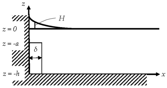
Figure 1.
A plunging breaking wave approaches and hits violently the wall creating an air cavity of infinitesimal width . The wave propagates from right to left. The height of the liquid from the bottom, up to the undisturbed free surface before the impact is .
Within the linearized realm of the potential theory, the investigated hydrodynamic impact is governed by the following bvp:
Clearly, the velocity potential is denoted by and the problem is set into the two-dimensional (2D) space. Equation (1) is the Laplace equation that should hold in the entire liquid field, Equation (2) is the Neumann condition on the impacted part of the wall, while Equation (3) is the dynamic boundary condition on the front of the liquid in the cavity. No kinematic condition is considered in the liquid front of the cavity and accordingly no disturbance is taken into consideration. Note that Equation (3) is directly imposed on the wall, due to the negligible width of the cavity. Further, Equation (4) is the bottom condition, Equations (5) and (6) are respectively the linearized kinematic and dynamic boundary conditions on the free surface at and finally, Equation (7) is the far-field condition, which implies that any disturbance caused by the collision with the wall should vanish at infinity.
3. Perturbation Analysis
The problem is considered at the very early stages of the impact. Using the small-time approximation, we are allowed to expand the original governing set of Equations (1)–(7) into a sequence of perturbation systems. Clearly, the perturbation parameter is the time variable , which is assumed indefinitely small. The perturbation series for the velocity potential and the wave elevation are taken in the form
Conditions (5) and (6) hold on the unknown boundary (interface between the liquid and the air) . To cope with this issue and to convert the conditions on the fixed boundary of the undisturbed free surface, the relevant equations are expanded using a Taylor series around .
Using Equations (8) and (9), Equations (10) and (11) are transformed into
Clearly, Equations (12) and (13) correspond to Equations (5) and (6). Higher order terms are accordingly omitted. For employing the perturbation analysis, we assume that . Hence, the bvp is composed by Equations (1)–(4), (7), (12) and (13) and equating like powers of , we obtain the perturbation systems at and , in terms of the leading- and the higher-order potentials and , respectively. Clearly, the derivation of through the associated system dictates the solution of the leading order problem.
3.1. The Leading Order Problem
The elevation is obtained from Equation (12) after equating powers of as
3.2. The Higher Order Problem
The elevation is obtained from Equation (12) after equating powers of as
Clearly, higher order problems are omitted. The evaluation of dictates the solution of the leading order bvp for . The elevations and are detached from the bvps and they can be obtained explicitly from the potentials. The solution of the higher order mixed bvp in terms of and is left for a future endeavor.
4. Solution for the Leading Order Mixed bvp
The leading order of the velocity potential is obtained from the solution of Equations (14)–(19). Using separable solutions for the Laplace equation, and taking into account Equations (17)–(19), it follows that
Expansion (28) satisfies Equations (14) and (17)–(19). The remaining Equations (15) and (16) determine a bvp of mixed type, which using Equation (28) yields
Both series of Equations (29) and (30) are divergent at . This dual trigonometrical series [38,39], reveals a singularity for the velocity, explicitly at . Letting and , the system of Equations (29) and (30) becomes identical with the one reported and analyzed by Sneddon [40] (pp.151, 152), namely
for the special case . Note that herein is a constant. The solution to this problem is taken directly from Sneddon (p. 158), which reads
where denotes the th degree Legendre Polynomial and
The constant yields from
Substituting the constant value for into the above formulas, does not simplify significantly the computations. Without loss of generality, we may assume that . All the elliptic integrals employed in this research are calculated using MATLAB’s [41] built-in function “integral”, which allows the efficient approximation of improper integrals. The differentiations and accordingly the sought expansion coefficients are treated numerically as well. Figure 2 shows a relative oscillating behavior for the expansion coefficients for and a progressive decrease to zero for higher modes. This implies a fast convergence for the solution sought. For the test cases examined herein, the computations employed nearly 200 modes, which secured a convergence of four significant digits for the velocity potential.
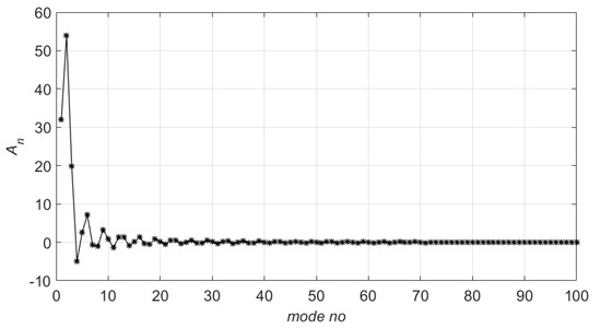
Figure 2.
The expansion coefficients , , for , and s.
5. Hydrodynamic Pressure Distribution and Free-Surface Elevation
The pressure distribution in the liquid field is obtained from the linear term of the Bernoulli’s equation
The pressure exerted exactly on the wall, can be simply calculated by substituting in Equation (37). It is important to mention that due to the uncoupling of the potential from time using the perturbation series expansion, the pressure is literally calculated for a specific wave shape that hits the wall at a specific time instant.
The free-surface elevation is obtained from Equation (20), using again , as
Letting next , Equation (38) is cast into the time dependent form
It should be mentioned that Equation (39) is divergent explicitly on the wall at . That has been verified numerically given that the expansion coefficients are also obtained numerically to cope with the mixed bvp involved. For a solid impermeable wall, the corresponding series that provides the free-surface elevation yields a closed-form analytical solution [42], which also grows indefinitely at . From the physical point of view, the mathematical singularity could be attributed to the water jet that is formed at the instant of impact. King and Needham [42] investigated the problem of the sudden acceleration of an impermeable wall (in 2D) that bounds a volume of liquid, initially at rest and they showed that the liquid run-up on the wall is obtained from
where is a parameter that expresses the ratio between the wall acceleration to the gravitational acceleration. Clearly, the series in Equation (40) yields a unique solution which is singular as , namely explicitly on the wall. To cope with the singular asymptotic behavior at , King and Needham [42] assumed two regions: (i) an outer region (), where the expansion for the free-surface elevation (relied on the small-time approximation) is valid and (ii) an inner region (), where the magnitude of the previously neglected terms of the Euler momentum equations they used are of the same magnitude as those retained. In the latter case they applied a different kind of expansion. In detail, the assumed expansion reads
where and denote respectively the first and second order free-surface elevations in the inner region, while is the time.
The assumptions taken by King and Needham [42] could be used in the present formulation, provided that the sums of Equations (38) and (40) exhibit the same behavior for . The variations of the concerned sums relative to the mode number are shown in Figure 3. Both sums grow indefinitely with the mode number and eventually become infinite. Although evident differences are observed, it can be easily deduced that they nearly coincide, and they become indistinguishable for large truncation of the sums. The wavy trend of the mixed bvp sum of Equation (38), is attributed to the values of the expansion coefficients . Accordingly, the mixed bvp methodology discussed in the present is enhanced with King and Needham’s [42] asymptotic analysis formulas explicitly for .
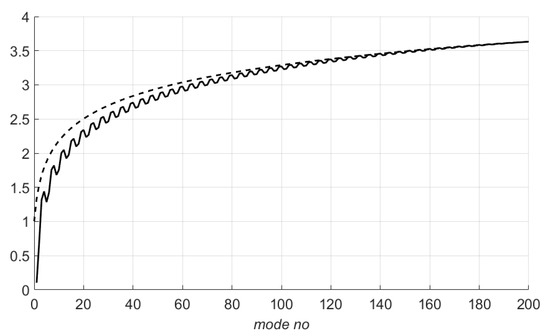
Figure 3.
Solid line: shows the behavior of sum of Equation (38). Dashed line: shows the behavior of sum of Equation (40), both for ; s.
In accord with the aforementioned discussion, the free-surface elevation can be approximated by
Following the asymptotic expansion suggested by King and Needham [42], one gets for the inner region
Expression (43) has no singularity neither for or . In order to derive the complete expression for the free-surface elevation in the inner region, one finds
6. Results
The leading order velocity potential derived in Section 4, exhibits several interesting characteristics. Figure 4 shows that the wave impact velocity affects directly the potential distribution. In detail, the greater the velocity, the wider the curve is.
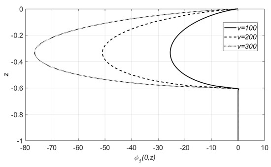
Figure 4.
First order velocity potentials on the wall, , for several wave impact velocities and fixed air cavity position at .
Further, Figure 5 shows that the velocity potential far from the free surface , is not identical even in the same impacted region and is strongly influenced by the air cavity position. In both Figure 4 and Figure 5, one can easily observe the semi-elliptical shape of the potential in the impacted region. Beyond it, in the air pocket cavity, is equal to zero, satisfying explicitly the Dirichlet dynamic boundary condition on the wall.
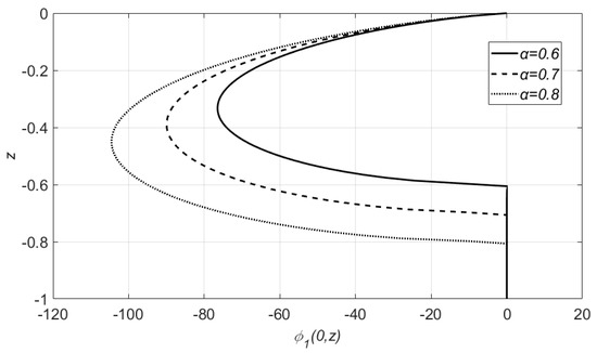
Figure 5.
First order velocity potentials on the wall, , for several air cavity positions and fixed wave impact velocity at .
Figure 6 shows the velocity profiles connected with the test cases included in Figure 4. In the impacted region the velocity is constant, while in the air pocket region a rapid decrease close to zero is observed. Furthermore, an evident discontinuity occurs at , i.e., at the point where the formed cavity ends up, revealing a clear singularity for the velocity. It should be made clear that the observed singularity does not mean that the liquid penetrates the wall. In contrast, the singularity is evidence of jet formation.
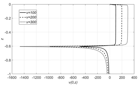
Figure 6.
Wave impact velocity on the wall, for fixed air cavity position and .
Figure 7 and Figure 8 depict the profiles of the hydrodynamic pressure distributions in a liquid field of . The hydrodynamic pressure exhibits, as expected, the same pattern with the velocity potential. This assumption is validated by the 3D graph of Figure 7, where the vertical semi-elliptical configuration and the zero pressure in the air pocket are evident. Moreover, one can easily observe the exponential decrease of the pressure with the distance from the wall.
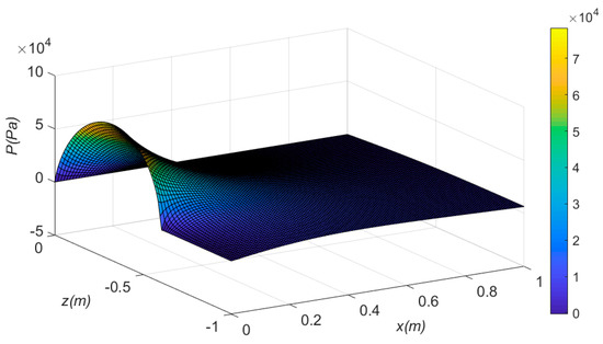
Figure 7.
Hydrodynamic pressure distributions in the liquid field for and fixed air cavity position at .
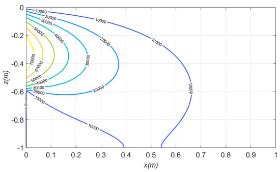
Figure 8.
Contours of the hydrodynamic pressure in the liquid domain for fixed air cavity position , fixed wave impact velocity and .
The contours of the hydrodynamic pressure (that correspond to Figure 7) are shown in Figure 8. The isobaric lines testify that the highest pressures occur in the wave impact zone.
Figure 9 shows that the portion of the water, which collides with the wall, in the region of the free surface, is characterized by a greater run-up on the wall, as time evolves. Finally, Figure 10 depicts the free-surface elevation for three different test cases. The wave run-up increases as the velocity is increased, a result which is totally reasonable. Nevertheless, an interesting result deduced from both figures is that for distance from the wall greater than , the free surface is calm and coincides with the undisturbed level.
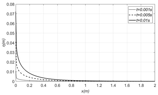
Figure 9.
Free-surface elevations on the wall for different time instants, normalized wave impact velocity and fixed air cavity position .
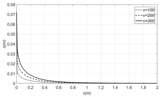
Figure 10.
Free-surface elevations on the wall for different normalized wave impact velocities, at and fixed air cavity position .
7. Conclusions
The present study treated the 2D problem of a plunging-like breaking wave impacting an impermeable wall. Linear potential theory was used along with the small-time approximation in order to eliminate the time-dependence from the solution. A perturbation method was used to satisfy the kinematic and the dynamic boundary conditions of the free surface on a fixed boundary, i.e., the still water level. The governing bvp of mixed type is solved analytically for the leading order of the velocity potential. The Neumann boundary condition on the impacted region and the Dirichlet condition beyond that must be satisfied, leading to a dual trigonometric series problem. The solution provided is based on the assumptions that the pressure in the cavity is zero and the compression effects are neglected. The singularity occurred in the intersection point of the free surface and the wall was tackled by adjusting the theory presented in the seminal paper of King and Needham [42].
Numerical results are cited in terms of the velocity potential, velocity profiles, hydrodynamic pressure distributions for several impacting velocities and air cavity positions. Figures for the free-surface elevations are also provided showing the deformation over time and over the wave impact velocities. The main outcome of this research is that the peak pressure is situated in the middle of the impacted region of the wall. Further, the presence of the air pocket significantly affects the pressure distribution on the wall, even in the same impacted region, especially for increasing depth, and for the same hitting velocity. An interesting result is that for relative long distances from the impacted region, no deformation of the free-surface occurs.
It is the intention of the authors to extend this study by (i) considering a time varying intersection point a on the wall and (ii) solving the higher-order perturbation problem that is formulated via Equations (21)–(27). Clearly, the reasonable outcomes of the study should be validated against experimental measurements.
Author Contributions
The problem and the solution methodology were conceived by I.K.C. The formal analysis and the investigation were accomplished by T.D.T. The code was developed by T.D.T. The results were validated by both authors. The manuscript was written by T.D.T and the work was supervised by I.K.C. All authors have read and agreed to the published version of the manuscript.
Funding
This research was partially funded by the Research Committee of the National Technical University of Athens.
Conflicts of Interest
The authors declare no conflict of interest.
References
- Faltinsen, O.M.; Landrini, M.; Greco, M. Slamming in marine applications. J. Eng. Math. 2004, 48, 187–217. [Google Scholar] [CrossRef]
- Faltinsen, O.M.; Chezhian, M. A Generalized Wagner Method for Three-Dimensional Slamming. J. Ship Res. 2005, 49, 279–287. [Google Scholar]
- Korobkin, A.A.; Khabakhpasheva, T.I. Regular wave impact onto an elastic plate. J. Eng. Math. 2006, 55, 127–150. [Google Scholar] [CrossRef]
- Khabakhpasheva, T.I.; Korobkin, A.A.; Malenica, S. Fluid impact onto a corrugated panel with trapped gas cavity. Appl. Ocean Res. 2013, 39, 97–112. [Google Scholar] [CrossRef][Green Version]
- Korobkin, A.A.; Scolan, Y.-M. Three-dimensional theory of water impact. Part 2. Linearized Wagner problem. J. Fluid Mech. 2006, 549, 343–373. [Google Scholar] [CrossRef]
- Scolan, Y.-M.; Korobkin, A.A. Three-dimensional theory of water impact. Part 1. Inverse Wagner problem. J. Fluid Mech. 2001, 440, 293–326. [Google Scholar] [CrossRef]
- Scolan, Y.-M. Hydrodynamic impact of an elliptic paraboloid on cylindrical waves. J. Fluids Struct. 2014, 48, 470–486. [Google Scholar] [CrossRef]
- Chatjigeorgiou, I.K. An analytical approach for the three-dimensional water entry problem of solids creating elliptical contact regions. J. Fluids Struct. 2019, 91, 102703. [Google Scholar] [CrossRef]
- Chatjigeorgiou, I.K.; Cooker, M.J.; Korobkin, A.A. Three-dimensional water impact at normal incidence to a blunt structure. Proc. R. Soc. A 2016, 472, 20150849. [Google Scholar] [CrossRef]
- Chatjigeorgiou, I.K.; Korobkin, A.A.; Cooker, M.J. Three-dimensional steep wave impact on a vertical plate with an open rectangular section. Int. J. Mech. Sci. 2017, 133C, 260–272. [Google Scholar] [CrossRef][Green Version]
- Tranter, C.J. Some triple integral equations. Glasgow Math. J. 1960, 4, 200–203. [Google Scholar] [CrossRef]
- Tsaousis, T.D.; Papadopoulos, P.K.; Chatjigeorgiou, I.K. A semi-analytical solution for the three-dimensional Wagner steep wave impact on a vertical circular cylinder. J. Appl. Math. Model. 2020, 77, 902–921. [Google Scholar] [CrossRef]
- Tu, Y.; Cheng, Z.; Muskulus, M. A review of slamming load application to offshore wind turbines from an integrated perspective. Energy Procedia 2017, 137, 346–357. [Google Scholar] [CrossRef]
- Guo, Y.; Xiao, L.; Teng, X.; Kou, Y.; Liu, J. Processing method and governing parameters for horizontal wave impact loads on a semi-submersible. J. Mar. Struct. 2020, 69, 102673. [Google Scholar] [CrossRef]
- Oumeraci, H.; Klammer, P.; Partenscky, H.W. Classification of breaking wave loads on vertical structures. J. Waterw. Port C. ASCE 1993, 119, 381–397. [Google Scholar] [CrossRef]
- Liu, S.; Gatin, I.; Obhrai, C.; Ong, M.C.; Jasak, H. CFD simulations of violent breaking wave impacts on a vertical wall using a two-phase compressible solver. J. Coast. Eng. 2019, 154, 103564. [Google Scholar] [CrossRef]
- Chella, M.A.; Collados, X.R.; Bihs, H.; Myrhaug, D.; Arntsen, O.A. Numerical and experimental investigation of breaking wave interaction with a vertical slender cylinder. Energy Procedia 2016, 94, 443–451. [Google Scholar] [CrossRef][Green Version]
- Song, B.; Zhang, C. Boundary element study of wave impact on a vertical wall with air entrapment. J. Eng. Anal. Bound. Elem. 2018, 90, 26–38. [Google Scholar] [CrossRef]
- Plumerault, L.-R.; Astruc, D.; Maron, P. The influence of air on the impact of a plunging breaking wave on a vertical wall using a multifluid model. J. Coast. Eng. 2012, 62, 62–74. [Google Scholar] [CrossRef]
- Jensen, A. Solitary wave impact on a vertical wall. Eur. J. Mech. B Fluids 2019, 73, 69–74. [Google Scholar] [CrossRef]
- Scolan, Y.-M. Some aspects of the flip-through phenomenon: A numerical study based on the disingularized technique. J. Fluids Struct. 2010, 26, 918–953. [Google Scholar] [CrossRef]
- Korobkin, A.A. Non-classical boundary conditions in water-impact problems. In IUTAM Symposium on Fluid Structure Interaction in Ocean Engineering; Springer: Berlin/Heidelberg, Germany, 2008; pp. 167–178. [Google Scholar]
- Cooker, M.J.; Peregrine, D.H. Violent water motion at breaking-wave impact. In Proceedings of the 22nd International Conference on Coastal Engineering, Delft, The Netherlands, 2–6 July 1990; ASCE: New York, NY, USA, 1990; pp. 164–176. [Google Scholar]
- Kamath, A.; Chella, M.A.; Bihs, H.; Arntsen, O.A. Breaking wave interaction with a vertical cylinder and the effect of breaker location. J. Ocean Eng. 2016, 128, 105–115. [Google Scholar] [CrossRef]
- Bullock, G.N.; Obhrai, C.; Peregrine, D.H.; Bredmose, H. Violent breaking wave impacts. Part 1: Results from large-scale regular wave tests on vertical and sloping walls. J. Coast. Eng. 2007, 54, 602–617. [Google Scholar] [CrossRef]
- Lugni, C.; Brocchini, M.; Faltinsen, O.M. Wave impact loads: The role of the flip-through. J. Phys. Fluids 2006, 18, 122101. [Google Scholar] [CrossRef]
- Hattori, M.; Arami, A.; Yui, T. Wave impact pressure on vertical walls under breaking waves of various types. J. Coast. Eng. 1994, 22, 79–114. [Google Scholar] [CrossRef]
- Kisacik, D.; Tarakcioglu, G.O.; Troch, P. Wave-induced uprush jet velocity on a vertical structure. J. Ocean Eng. 2016, 127, 103–113. [Google Scholar] [CrossRef]
- Peregrine, D.H. Water-wave impact on walls. Annu. Rev. Fluid Mech. 2003, 35, 23–43. [Google Scholar] [CrossRef]
- Hattori, M.; Arami, A. Impact breaking wave pressures on vertical walls. In Proceedings of the 23rd International Conference on Coastal Engineering, Venice, Italy, 4–9 October 1992; ASCE: New York, NY, USA, 1992; pp. 1785–1798. [Google Scholar]
- Bagnold, R.A. Interim report on wave pressure research. J. I. Civil Eng. 1939, 12, 201–226. [Google Scholar]
- Cooker, M.J.; Peregrine, D.H. Pressure-impulse theory for liquid impact problems. J. Fluid Mech. 1995, 297, 193–214. [Google Scholar] [CrossRef]
- Martin-Medina, M.; Abadie, S.; Mokrani, C.; Morichon, D. Numerical simulation of flip-through impacts of variable steepness on a vertical breakwater. J. Appl. Ocean Res. 2018, 75, 117–131. [Google Scholar] [CrossRef]
- Chan, E.S. Mechanics of deep water plunging-wave impacts on vertical structures. J. Coastal Eng. 1994, 22, 115–133. [Google Scholar] [CrossRef]
- Chatjigeorgiou, I.K.; Korobkin, A.A.; Cooker, M.J. Two-dimensional breaking wave impact on a vertical wall. In Proceedings of the 30th International Workshop on Water Waves and Floating Bodies, Bristol, UK, 12–15 April 2015; pp. 33–36. [Google Scholar]
- Wood, D.J.; Peregrine, D.H.; Bruce, T. Wave Impact on A Wall Using Pressure-Impulse Theory. I Trapped Air. J. Waterw. Port C. ASCE 2000, 126, 182–190. [Google Scholar] [CrossRef]
- Cooker, M.J.; Peregrine, D.H. A model for breaking wave impact pressures. In Proceedings of the 22nd International Conference on Coastal Engineering, Delft, The Netherlands, 2–6 July 1990; ASCE: New York, NY, USA, 1990; Volume 1, pp. 1473–1486. [Google Scholar]
- Tranter, C.J. Dual trigonometrical series. Glasgow Math. J. 1959, 4, 49–57. [Google Scholar] [CrossRef]
- Tranter, C.J. A further note on dual trigonometrical series. Glasgow Math. J 1960, 4, 198–200. [Google Scholar] [CrossRef]
- Sneddon, I.N. Mixed Boundary Value Problems in Potential Theory; North-Holland Publishing: Amsterdam, The Netherlands, 1966; pp. 151–152. [Google Scholar]
- Matlab®. R2017a. The Mathworks Inc., 2017. Available online: https://www.mathworks.com (accessed on 23 April 2020).
- King, A.C.; Needham, D.J. The initial Development of a jet caused by fluid, body and free-surface interaction. Part 1. A uniformly accelerating plate. J. Fluid Mech. 1994, 268, 89–101. [Google Scholar] [CrossRef]


© 2020 by the authors. Licensee MDPI, Basel, Switzerland. This article is an open access article distributed under the terms and conditions of the Creative Commons Attribution (CC BY) license (http://creativecommons.org/licenses/by/4.0/).