Computational Aerodynamics Analysis of Non-Symmetric Multi-Element Wing in Ground Effect with Humpback Whale Flipper Tubercles
Abstract
:1. Introduction
2. Computational Framework
2.1. Computational Domain
2.2. Validation Case
2.3. Meshing Strategy
2.4. Fluent Simulation
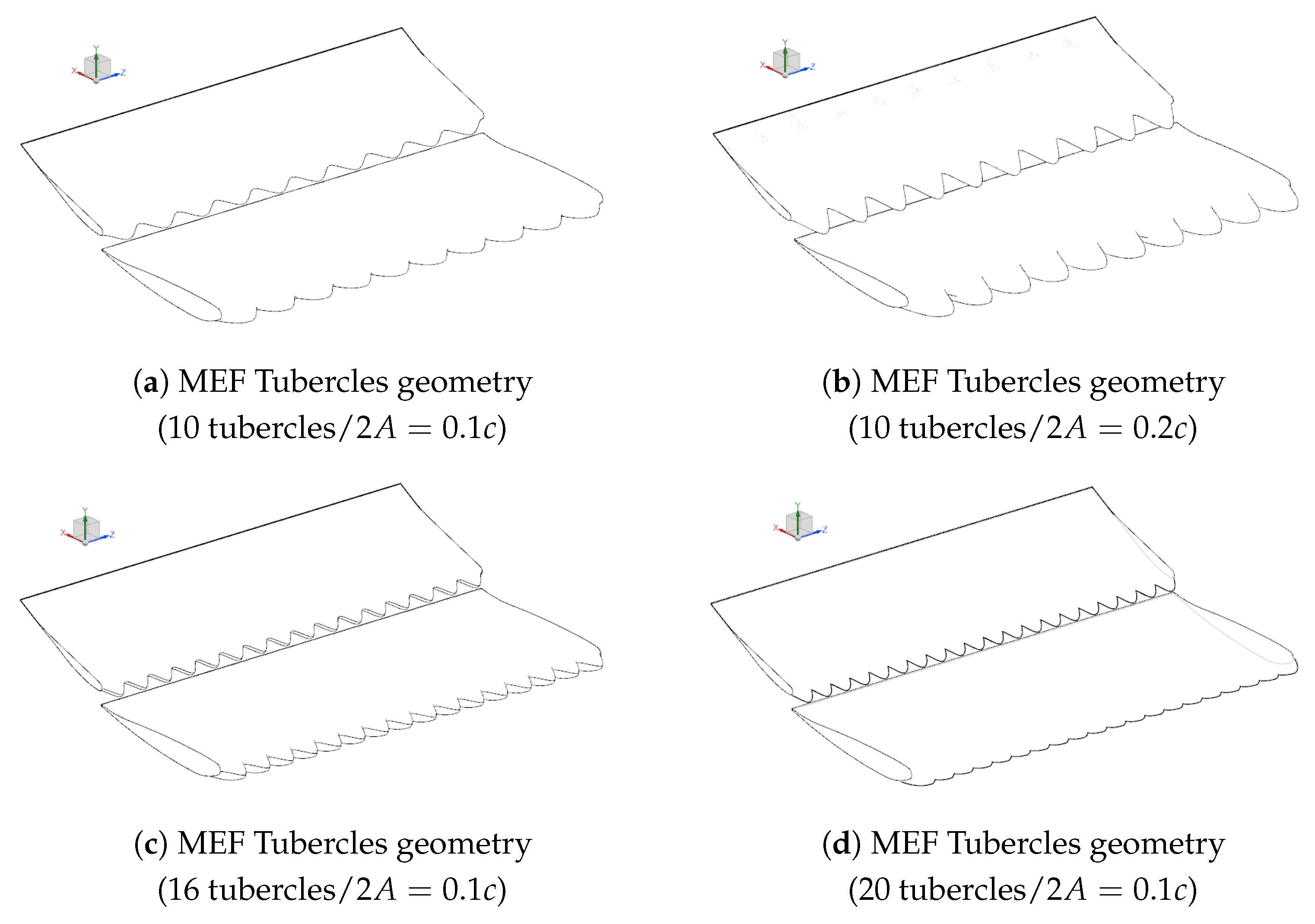
2.5. Investigation of Tubercles on the Front Wing
3. Results and Discussion
3.1. Validation Case
3.2. Investigation of Tubercles on the Front Wing
4. Conclusions
Concluding Remarks
- In stall conditions, for all geometries tested, tubercles improved the aerodynamic performance of the front wing, i.e., increased the downforce generation but at the cost of an increase of the drag. Nevertheless, the L/D ratio was increased for each geometry.
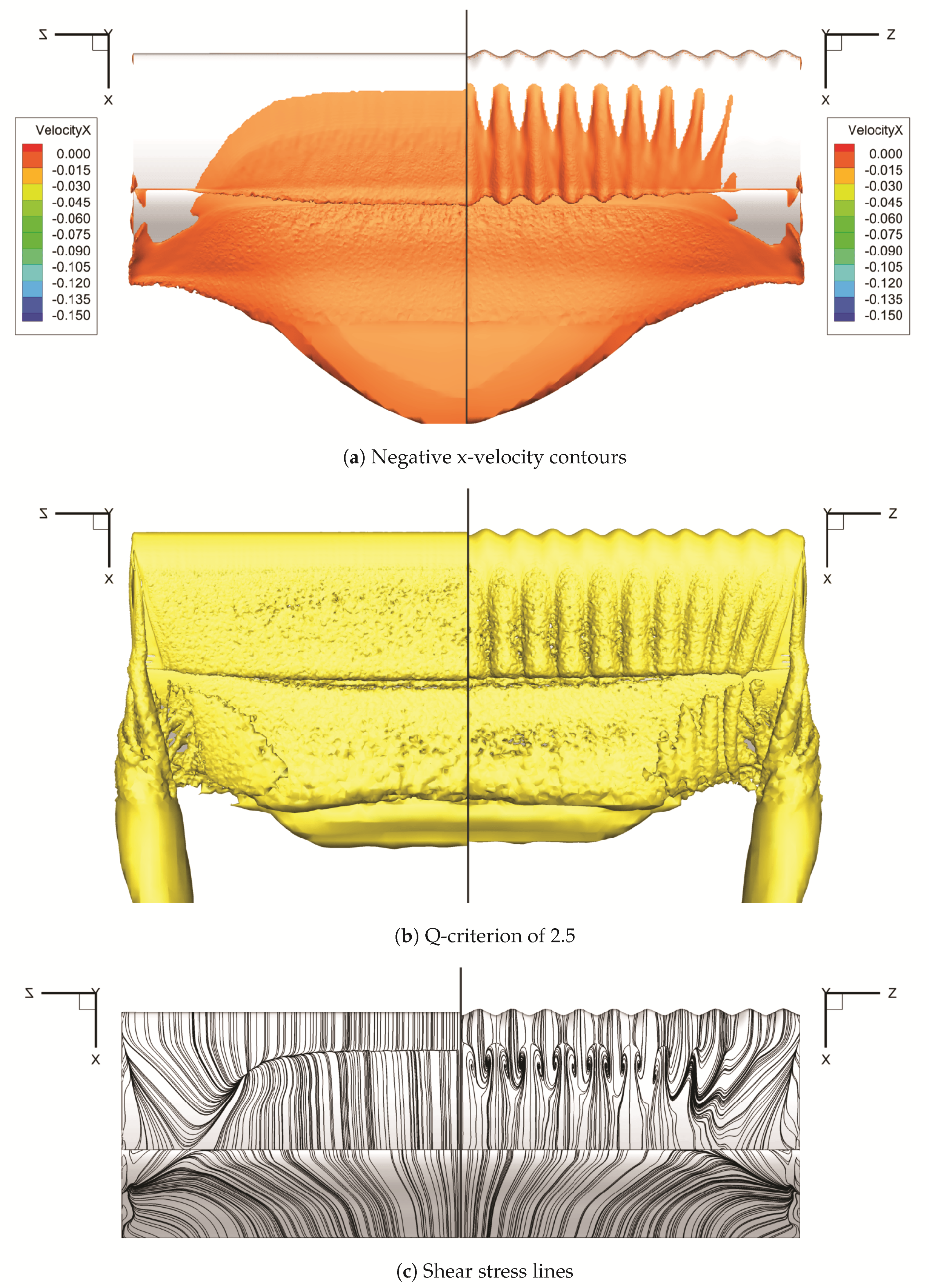
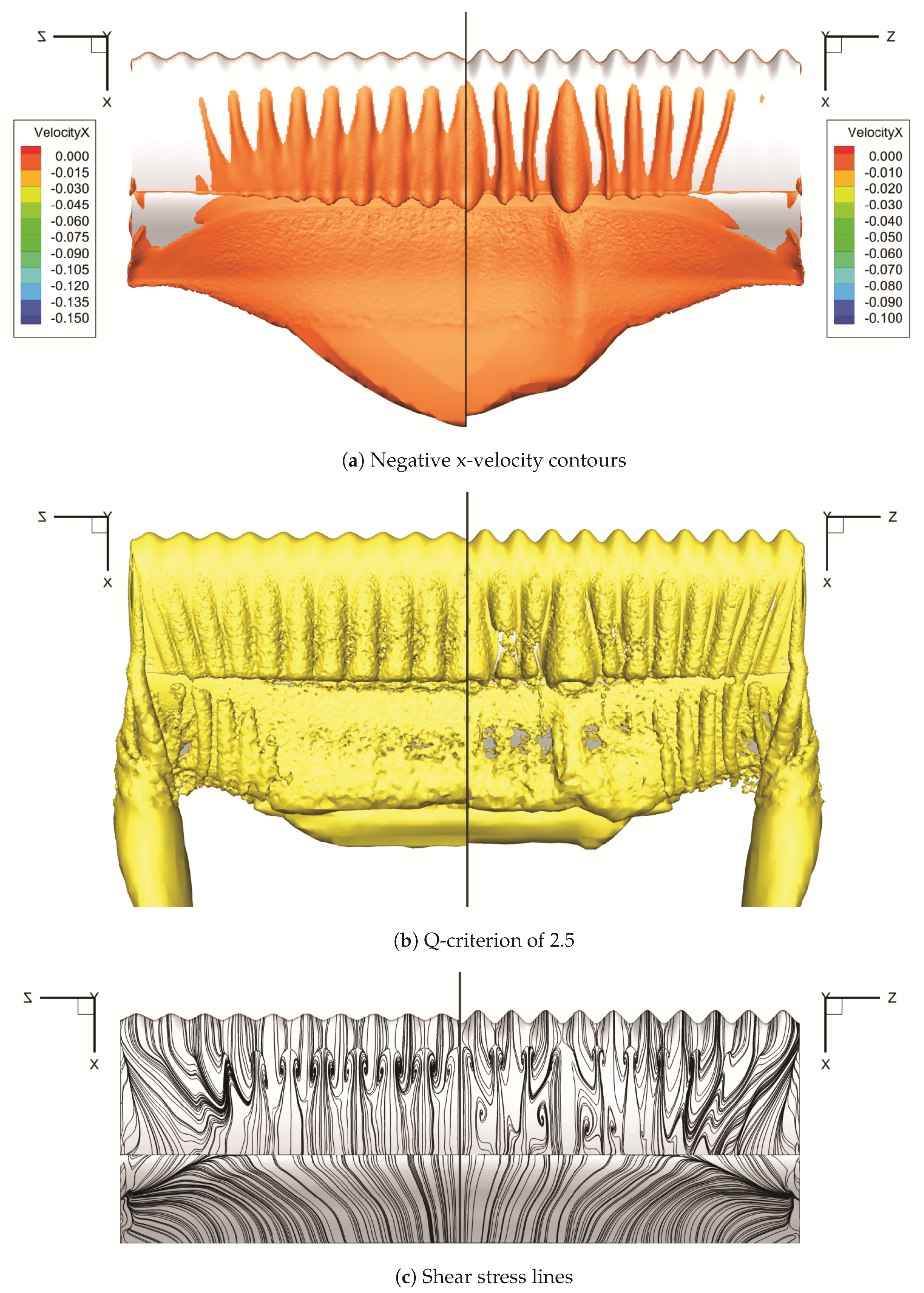
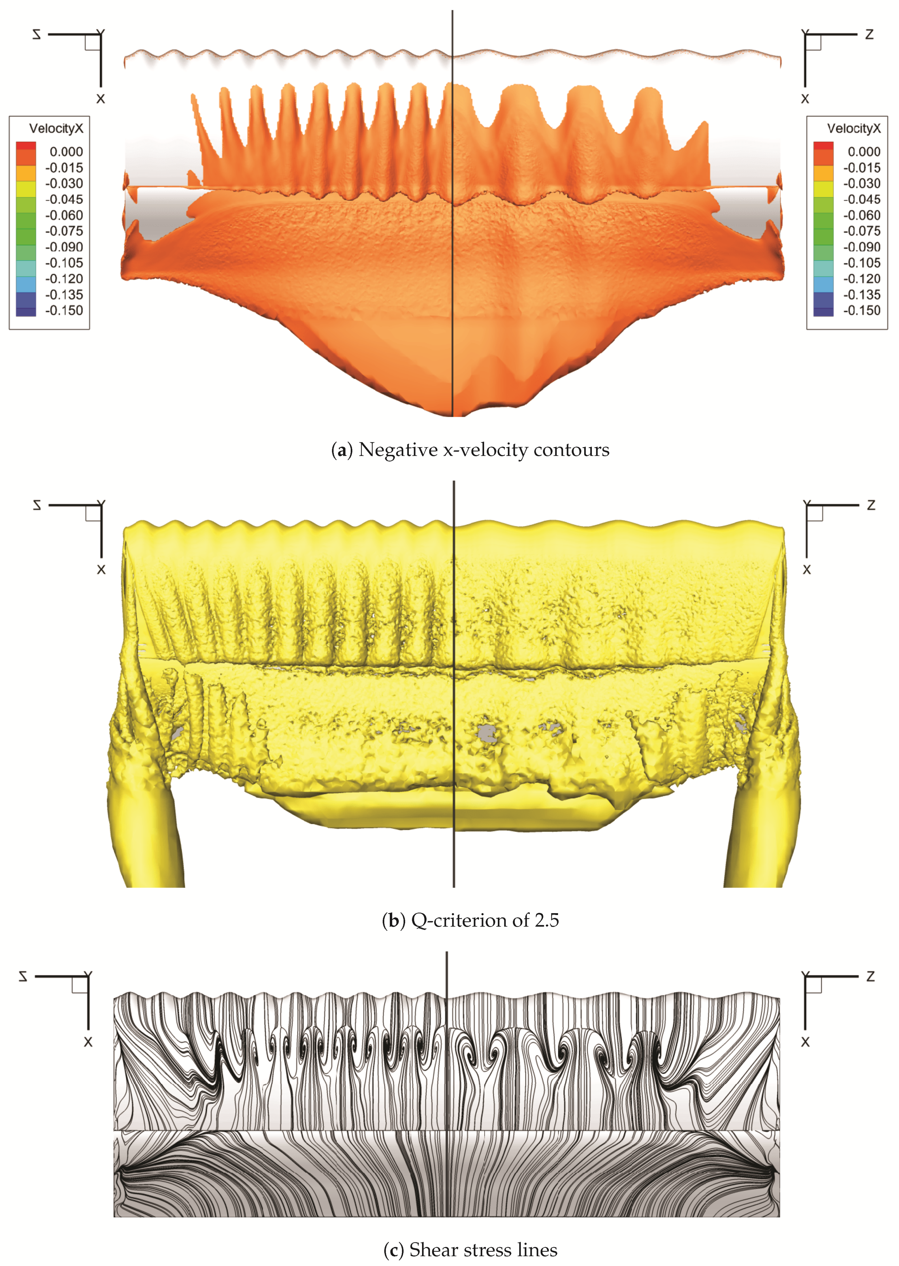
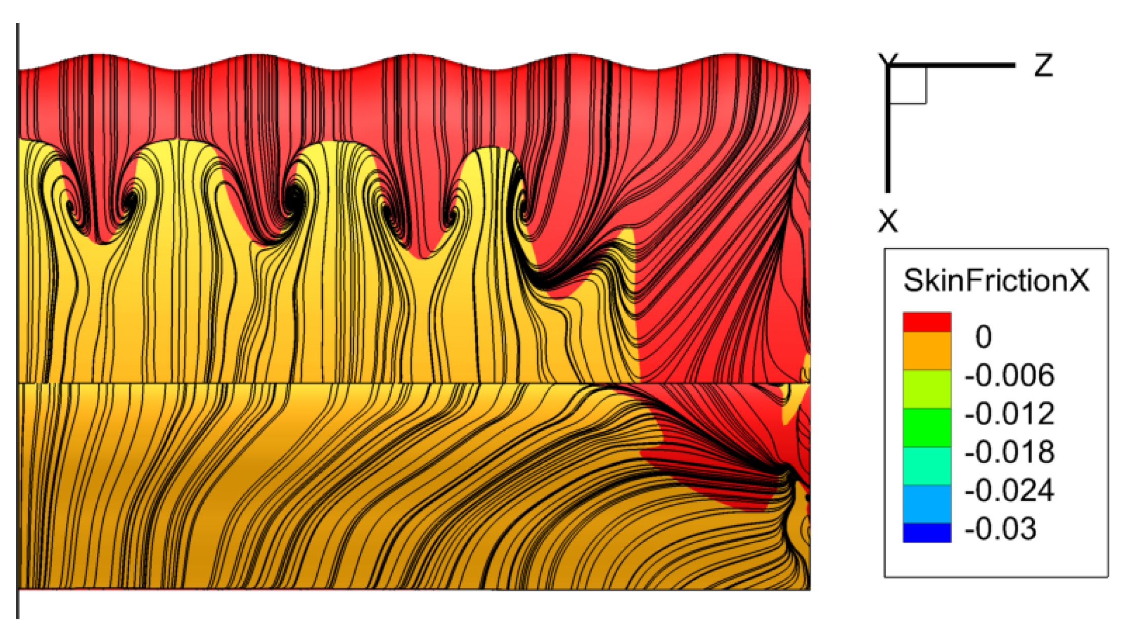
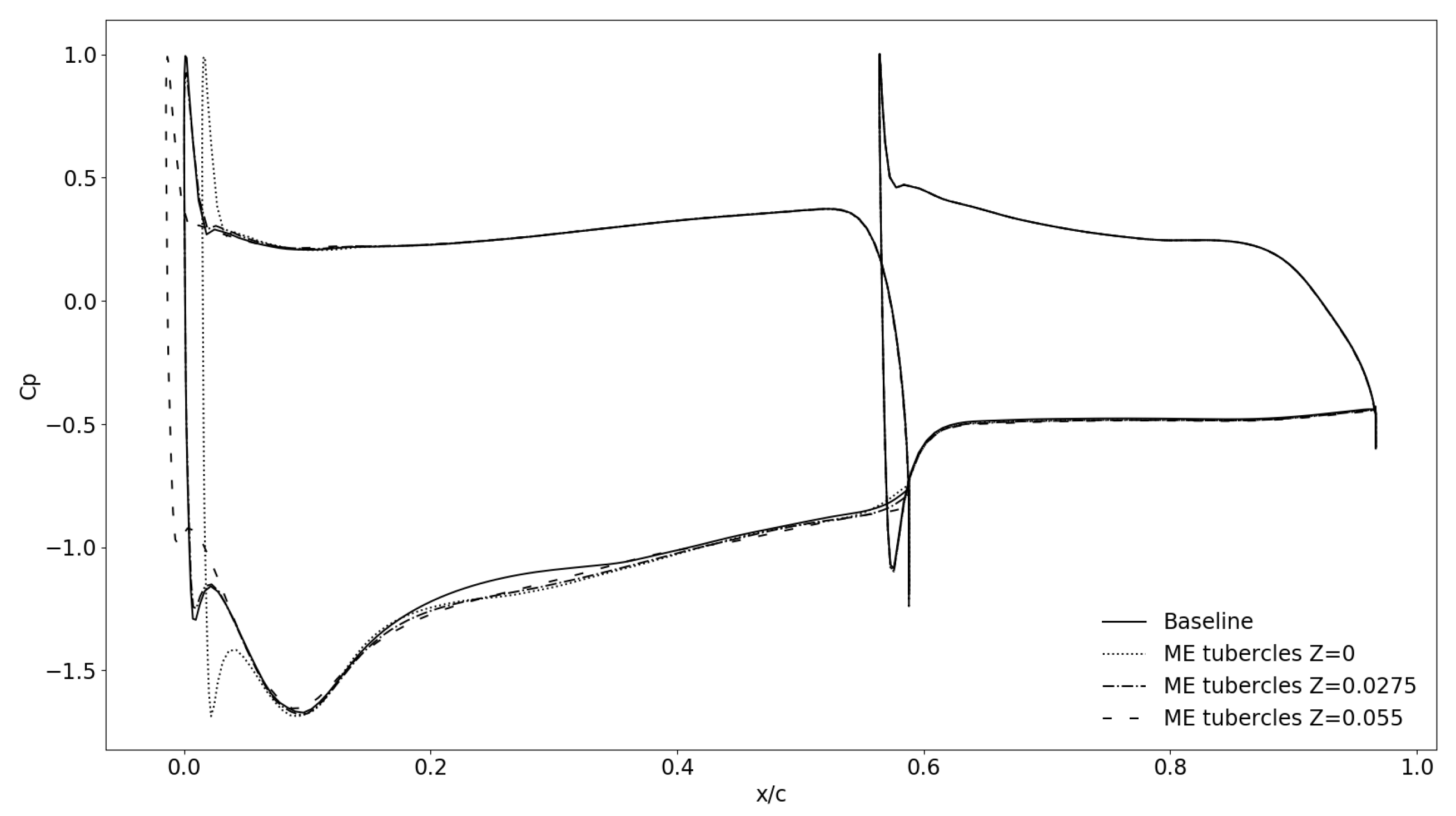
- By sets of underpressure and overpressure occurring, respectively, at tubercular and intertubercular sections, vortices are created in the flow field, at intertubercular sections. Those vortices carry momentum in the boundary layer that delays the stall in intertubercular sections, at the cost of triggering earlier the stall in tubercular sections.
- The more upstream the tubercles are, the more impact on the flow and aerodynamic coefficients they have.
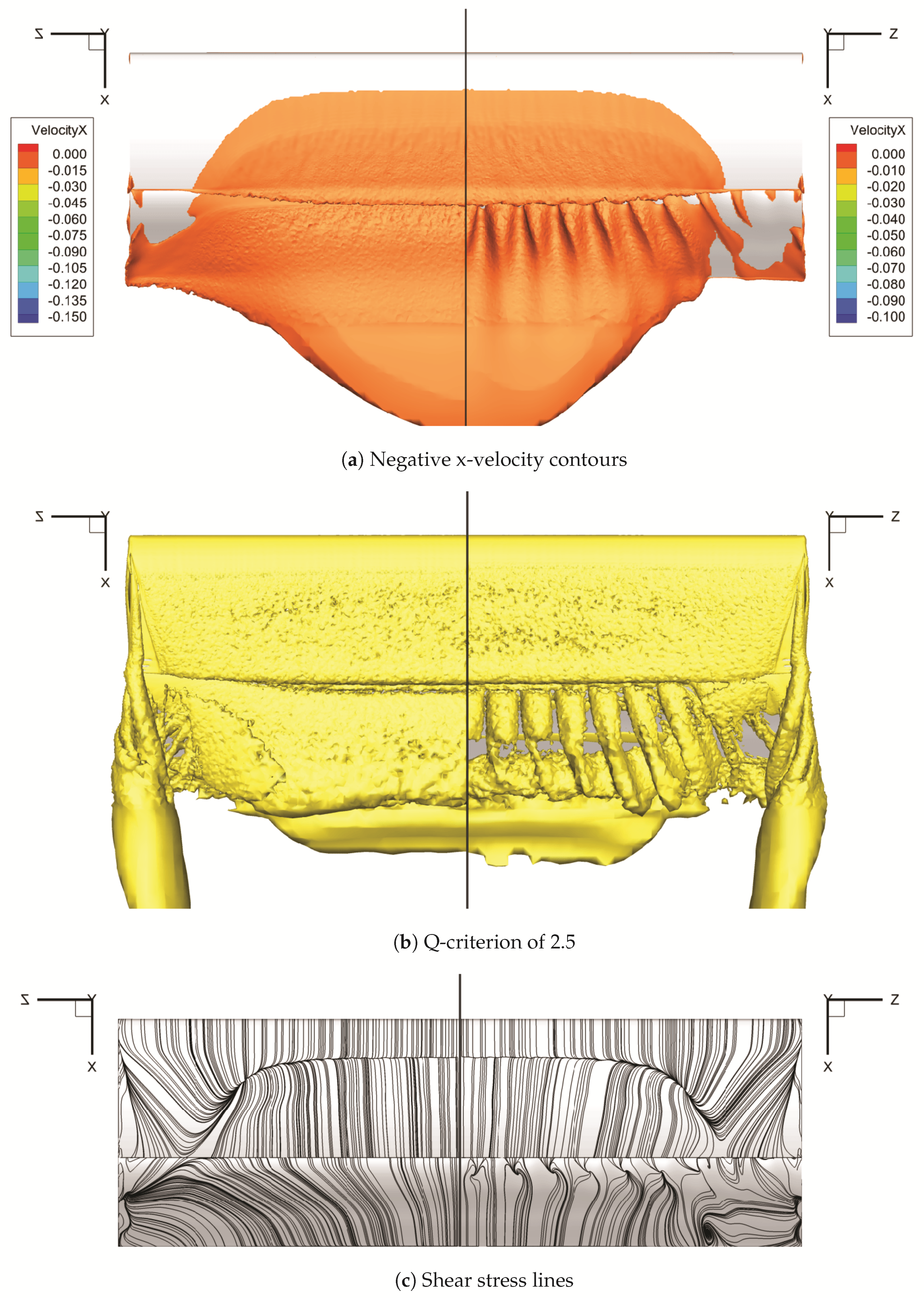
- One important aspect of the tubercles is that they alter the creation of the recirculations on the wing that improve the aerodynamic performance. Nevertheless, they can lead to the creation of big recirculations that are chaotic by their positions. For each geometry, the big recirculations highly impact the results.
- Compared to what was stated by Hansen K. L. [11], it can be said that an optimal configuration can be found for any geometry. Even if having more tubercles with a bigger amplitude seems better, as it reduces the size of the overall recirculation on the front wing, it alters the aerodynamic performance of the wing. This shows the tubercles are case-dependent.
Author Contributions
Funding
Acknowledgments
Conflicts of Interest
Abbreviations
| CFD | Computational Fluid Dynamics |
| F1 | Formula 1 |
| FIA | International Automobile Federation |
| RANS | Reynolds-Averaged Navier–Stokes |
| LES | Large-Eddy Simulation |
| DNS | Direct Numerical Simulations |
| URANS | Unsteady Reynolds-Averaged Navier–Stokes |
| IDDES | Improved Delayed Detached-Eddy Simulation |
| LBM | Lattice Boltzmann Method |
| ME Tubercles | Geometry with tubercles on the main element |
| F Tubercles | Geometry with tubercles on the flap |
| MEF Tubercles | Geometry with tubercles on the main element and on the flap |
| GCI | Grid Convergence Index |
List of Symbols
| c | Chord length | m |
| , , | Length | m |
| H, h | Height | m |
| u, v, w | Velocity | m·s |
| , , | Drag, Lift and Pressure coefficient | |
| A | Amplitude | m |
| Specific turbulence dissipation rate | s | |
| Turbulence dissipation rate | m·s | |
| k | Turbulent kinetic energy | m·s |
| Density | kg·m | |
| Kinematic viscosity | m·s | |
| Dynamic viscosity | Pa·s | |
| Initial wall spacing | m | |
| Boundary layer height | m | |
| Expansion factor | ||
| ratio | Lift over drag ratio | |
| Dimensionless wall distance | ||
| Reynolds number | ||
| Mach number |
References
- Harish, A. Front Wing of an F1 Car: How to Optimize Its Design. Available online: https://www.simscale.com/blog/2016/10/front-wing-f1-car-optimize/ (accessed on 30 May 2020).
- FIA. 2021 Formula 1 Technical Regulations. Available online: https://www.fia.com/multimedia/publication/2021-formula-1-technical-regulations-published-6032020 (accessed on 15 June 2020).
- Alfredsson, P.H.; Örlü, R. Large-eddy-breakup-devices. A forty years perspective from Stockholm horizon. J. Combust. Turbul. 2018, 100, 877–888. [Google Scholar] [CrossRef] [PubMed]
- Chin, C.; Örlü, R.; Monty, J.; Hutchins, N.; Ooi, A.; Schlatter, P. Simulation of a Large-Eddy-Break-up Device (LEBU) in a Moderate Reynolds Number Turbulent Boundary Layer. Flow Turbul. Combust. 2017, 98, 445–460. [Google Scholar] [CrossRef]
- Cerutti, J.J.; Sardu, C.; Cafiero, G.; Iuso, G. Active Flow Control on a Square-Back Road Vehicle. Fluids 2020, 5, 55. [Google Scholar] [CrossRef] [Green Version]
- Alimi, A.W. Numerical Investigation of Steady and Harmonic Vortex Generator Jets Flow Separation Control. Fluids 2018, 3, 94. [Google Scholar] [CrossRef] [Green Version]
- Fish, F.E.; Battle, J.M. Hydrodynamic design of the humpback whale flipper. J. Morphol. 1995, 225, 51–60. [Google Scholar] [CrossRef] [PubMed]
- Miklosovic, D.S.; Murray, M.M.; Howle, L.E.; Fish, F.E. Leading-edge tubercles delay stall on humpback whale flippers. Phys. Fluids 2004, 16, L39–L42. [Google Scholar] [CrossRef] [Green Version]
- Fish, F.; Lauder, G.V. Passive and active flow control by swimming fishes and mammals. Annu. Rev. Fluid Mech. 2006, 38, 193–224. [Google Scholar] [CrossRef] [Green Version]
- Bushnell, D.M.; Moore, K.J. Drag reduction in nature. Annu. Rev. Fluid Mech. 1991, 23, 65–79. [Google Scholar] [CrossRef]
- Hansen, K.L.; Kelso, R.M.; Dally, B.B. An investigation of three-dimensional effects on the performance of tubercles at low reynolds numbers. In Proceedings of the 17th Australasian Fluid Mechanics Conference, Auckland, New Zealand, 5–9 December 2010. [Google Scholar]
- Hansen, K.L.; Kelso, R.M.; Dally, B.B. The formation mechanism and impact of streamwise vortices on NACA 0021 airfoil’s performance with undulating leading edge modification. Phys. Fluids 2014, 26, 107101. [Google Scholar] [CrossRef]
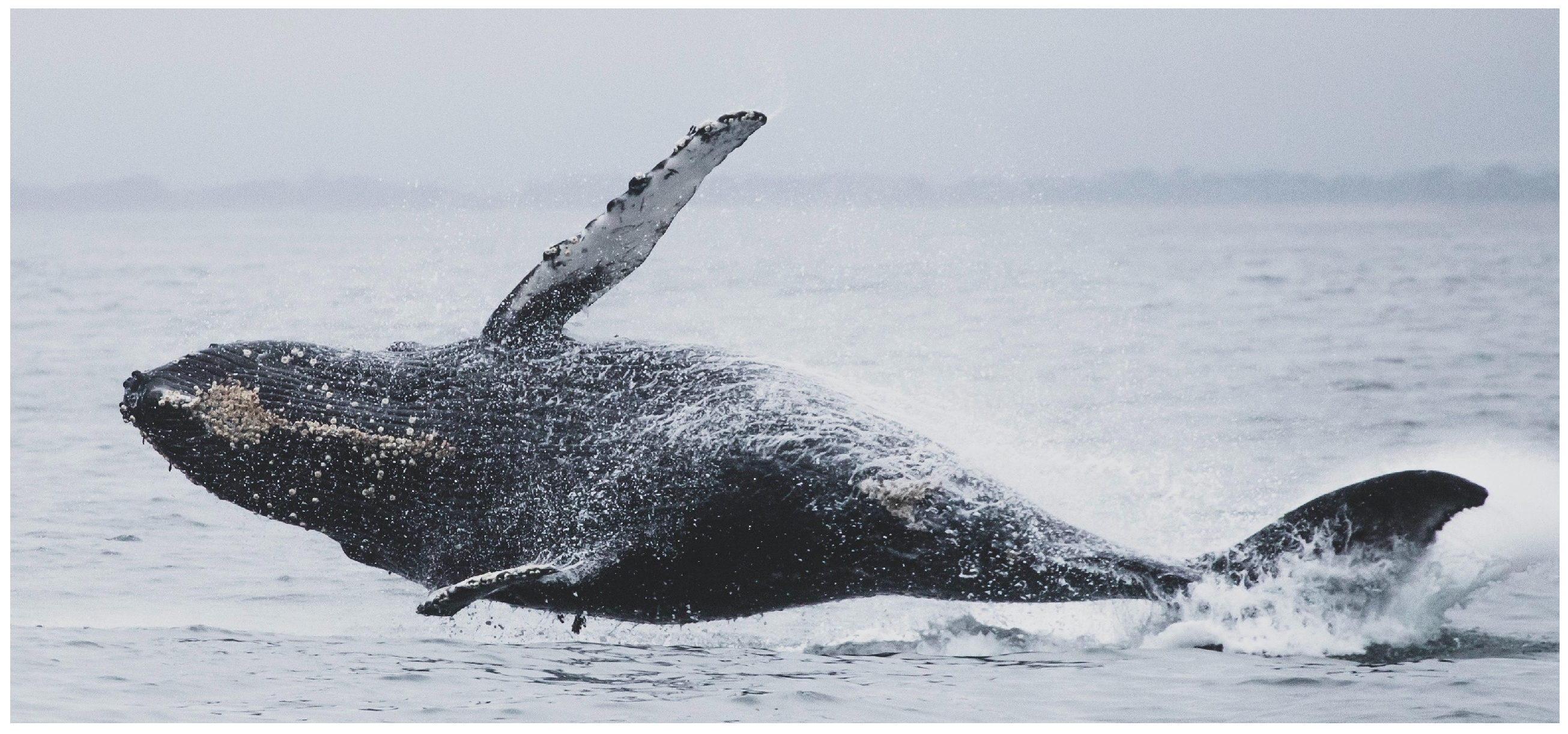
- Andre, E. Whale Jumping above Sea Water. Available online: https://www.pexels.com/photo/whale-jumping-above-sea-water-3309870/ (accessed on 31 October 2020).
- Miklosovic, D.S.; Murray, M.M.; Howle, L.E. Experimental evaluation of sinusoidal leading edges. J. Aircr. 2007, 44, 1404–1408. [Google Scholar] [CrossRef]
- Van Nierop, E.A.; Alben, S.; Brenner, M.P. How bumps on whale flippers delay stall: An aerodynamic model. Am. Phys. Soc. 2008, 100, 054502. [Google Scholar] [CrossRef] [PubMed] [Green Version]
- Castro, X.; Rana, Z.A. Aerodynamic and Structural Design of a 2022 Formula One Front Wing Assembly. Fluids 2020, 5, 237. [Google Scholar] [CrossRef]
- Carreira Pedro, H.; Kobayashi, M. Numerical study of stall delay on humpback whale flippers. In Proceedings of the 46th AIAA Aerospace Sciences Meeting and Exhibit, Reno, NY, USA, 7–10 January 2008. [Google Scholar]
- Srinivas, K.S.; Datta, A.; Bhattacharyya, A.; Kumar, S. Free-stream characteristics of bio-inspired marine rudders with different leading-edge configurations. Ocean. Eng. 2018, 170, 148–159. [Google Scholar] [CrossRef]
- Zerihan, J. An Investigation into the Aerodynamics of Wings in Ground Effect. Ph.D. Thesis, University of Southampton, Southampton, UK, 2001. [Google Scholar]
- Zerihan, J.; Zhang, X. Aerodynamics of a single element wing in ground effect. J. Aircr. 2000, 37, 1058–1064. [Google Scholar] [CrossRef]
- Zerihan, J.; Zhang, X. A single element wing in ground effect: Comparison of experiments and computation. In Proceedings of the 39th Aerospace Sciences Meeting and Exhibit, Reno, NV, USA, 8–12 January 2001. [Google Scholar]
- Zhang, X.; Zerihan, J. Aerodynamics of a double element wing in ground effect. J. Aircr. 2003, 41, 1007–1016. [Google Scholar] [CrossRef] [Green Version]
- Vogt, J.W.; Barber, T.J. Variation of ground effect phenomena about downforce generating Tyrrell and Naca4412 aerofoils. Int. J. Aerodyn. 2010, 1, 82–96. [Google Scholar] [CrossRef]
- Jamei, S.; Maimun, A.; Niazmand Bilandi, R.; Azwadi, N.; Mancini, S.; Vitiello, L.; De Carlini, M. Wake behind a compound wing in ground effect. J. Mar. Sci. Eng. 2020, 8, 156. [Google Scholar] [CrossRef] [Green Version]
- Sakellariou, K.; Rana, Z.A.; Jenkins, K.W. Optimisation of the surfboard fin shape using computational fluid dynamics and genetic algorithms. Proc. Inst. Mech. Eng. Part P J. Sports Eng. Technol. 2017, 231, 344–354. [Google Scholar] [CrossRef]
- Doig, G.; Barber, T.J.; Neely, A.J. The influence of compressibility of the aerodynamics of an inverted wing in ground effect. J. Fluids Eng. 2011, 133. [Google Scholar] [CrossRef]
- Vogt, J.W.; Barber, T.J.; Leonardi, E. Flow field phenomena about lift and downforce generating cambered aerofoils in ground effect. In Proceedings of the 16th Australasian Fluid Mechanics Conference, Gold Coast, Australia, 3–7 December 2007. [Google Scholar]
- Bagul, P.; Rana, Z.A.; Jenkins, K.W.; Konozsy, L. Computational engineering analysis of external geometrical modifications on MQ-1 unmanned combat aerial vehicle. Chin. J. Aeronaut. 2020, 33, 1154–1165. [Google Scholar] [CrossRef]
- He, Y. Shape Optimization of Airfoils without and with Ground Effect Using a Multi-Objective Genetic Algorithm. Master’s Thesis, School of Engineering and Applied Science of Washington University, St. Louis, MO, USA, 2014. [Google Scholar]
- Mahon, S.; Zhang, X. Computational analysis of pressure and wake characteristics of an aerofoil in ground effect. J. Fluids Eng. 2005, 127, 290–298. [Google Scholar] [CrossRef]
- Grabis, M.; Agarwal, R.K. Computational fluid dynamics analysis of high lift, inverted airfoils in ground effect. In Mechanical Engineering and Materials Science Independent Study; Washington University: St. Louis, MO, USA, 2018. [Google Scholar]
- Arrondeau, B.; Saravana, A.; Sabates, A.; Segura, D. Front wing design of a 2021 F1 race car. In GDP in MSc CFD; Cranfield University: Cranfield, UK, 2020. [Google Scholar]
- Simmonds, N.; Pitman, J.; Tsoutsanis, P.; Jenkins, K.W.; Gaylard, A.; Jansen, W. Complete body aerodynamic study of three vehicles. SAE Technical Paper. In Proceedings of the WCX17: SAE World Congress Experience, Detroit, MI, USA, 4–6 April 2017. [Google Scholar]
- Ashton, N.; West, A.; Lardeau, S.; Revell, A. Assessment of RANS and DES methods for realistic automotive models. Comput. Fluids 2016, 128, 1–15. [Google Scholar] [CrossRef] [Green Version]
- Gorostidi, N.; Lecourt, D.; Castro, X.; Maigler, M. Optimisation of aerofoil design. In GDP in MSc CFD; Cranfield University: Cranfield, UK, 2020. [Google Scholar]
- Calmet, I. Introduction—Boundary Layer & Turbulence; Lecture Notes; Ocean Engineering Module, Centrale Nantes Engineering School: Nantes, France, 2018. [Google Scholar]
- Schlichting, H. Boundary-Layer Theory, 7th ed.; McGraw-Hill: New York, NY, USA, 1979. [Google Scholar]
- Slater, J.W. Examining Spatial (Grid) Convergence. Available online: https://www.grc.nasa.gov/WWW/wind/valid/tutorial/spatconv.html (accessed on 29 January 2020).
- Roache, P.J.; Ghia, K.N.; White, F.M. Editorial policy statement on the control of numerical accuracy. ASME J. Fluids Eng. 1986, 108, 2. [Google Scholar] [CrossRef] [Green Version]




| Reference | H | |||
|---|---|---|---|---|
| Zerihan (2001) [19] | ||||
| GDP Front Wing (2020) [32] | ||||
| Doig et al. (2011) [26] | ||||
| Vogt et al. (2007) [27] | ||||
| He et al. (2014) [29] | ||||
| Mahon et al. (2005) [30] | ||||
| Grabis et al. (2018) [31] | ||||
| Simmonds et al. (2017) [33] |
| Coarse Mesh | Medium Mesh | Fine Mesh | |
|---|---|---|---|
| Number of element | 5,031,410 | 9,989,089 | 19,470,689 |
| of wing/ground | 1 | 0.79 | 0.63 |
| of wing/ground ( m) | 1.154 | 0.9159 | 0.7269 |
| of endplate | 3 | 2 | 1 |
| of endplate ( m) | 3.461 | 2.307 | 1.154 |
| Number of layers n | 20 | 25 | 30 |
| Expansion factor | 1.694 | 1.232 | 1.148 |
| Refinement region spacing (mm) | 20 | 15 | 10 |
| Farfield Region spacing (mm) | 152 | 114 | 76 |
| Coefficient | Experimental | Coarse Mesh | Medium Mesh | Fine Mesh |
|---|---|---|---|---|
| 0.254 | 0.2579 | 0.2584 | 0.2579 | |
| −2.6 | −2.414 | −2.369 | −2.378 |
| Coarse Mesh | Medium Mesh | Fine Mesh | |
|---|---|---|---|
| Spacing at both leading and trailing edge (in mm) | 0.1 | 0.01 | 0.005 |
| Number of element on the intrados of the main element | 94 | 124 | 156 |
| Exp. | Coarse Mesh | Medium Mesh | Fine Mesh | |
|---|---|---|---|---|
| at spike | −6.76 | −7.18 | −7.19 | −7.26 |
| at peak | −5.51 | −5.07 | −5.02 | −5.06 |
| 1st min | 0.38 | 0.61 | 0.55 | 0.51 |
| 1st min | 0.27 | 0.28 | 0.29 | 0.29 |
| 2nd min | 0.64 | 0.77 | 0.76 | 0.74 |
| 2nd min | 0.19 | 0.21 | 0.22 | 0.21 |
| Baseline geometry | 0.230 | −1.108 |
| ME Tubercles geometry (10 tubercles/) | 0.235 | −1.184 |
| F Tubercles geometry (10 tubercles/) | 0.238 | −1.148 |
| ME Tubercles geometry (10 tubercles/) | 0.242 | −1.223 |
| ME Tubercles geometry (5 tubercles/) | 0.233 | −1.127 |
| MEF Tubercles geometry (10 tubercles/) | 0.253 | −1.267 |
| MEF Tubercles geometry (16 tubercles/) | 0.257 | −1.359 |
| MEF Tubercles geometry (20 tubercles/) | 0.248 | −1.303 |
| MEF Tubercles geometry (10 tubercles/) | 0.262 | −1.182 |
| x/c | ||
|---|---|---|
| Baseline geometry | 0.025 | −1.30 |
| ME Tubercles geometry (5 tubercles/) at an intertubercular section | 0.058 | −1.69 |
| ME Tubercles geometry (5 tubercles/) at the middle between tubercle and intertubercular section | 0.026 | −1.25 |
| ME Tubercles geometry (5 tubercles/) at a tubercle section | −0.12 | −0.99 |
| Stall Position on the Main Element at the First Intertubercular Section (x/c) | Stall Position on the Main Element at the First Tubercular Section (x/c) | Stall Position on the Flap at the First Intertubercular Section (x/c) | |
|---|---|---|---|
| Baseline geometry | 0.167 | 0.167 | 0.564 |
| ME Tubercles geometry (10 tubercles/) | 0.335 | 0.139 | 0.564 |
| F Tubercles geometry (10 tubercles/) | 0.167 | 0.167 | 0.665 |
| ME Tubercles geometry (10 tubercles/) | 0.512 | 0.125 | 0.564 |
| ME Tubercles geometry (5 tubercles/) | 0.328 | 0.145 | 0.564 |
| MEF Tubercles geometry (10 tubercles/) | 0.552 | 0.126 | / |
| MEF Tubercles geometry (16 tubercles/) | 0.447 | 0.107 | / |
| MEF Tubercles geometry (20 tubercles/) | 0.382 | 0.107 | / |
| MEF Tubercles geometry (10 tubercles/) | 0.580 | 0.09 | / |
| Min. Negative X-Velocity | Total Average Negative X-Velocity | Relative Number of Cells with Reverse Flow | |
|---|---|---|---|
| Baseline geometry | −0.183 | −51,233 | 20.22 |
| ME Tubercles geometry (10 tubercles/) | −0.178 | −51,780 | 19.29 |
| F Tubercles geometry (10 tubercles/) | −0.213 | −48,277 | 18.41 |
| ME Tubercles geometry (10 tubercles/) | −0.203 | −48,346 | 17.61 |
| ME Tubercles geometry (5 tubercles/) | −0.192 | −51,132 | 19.64 |
| MEF Tubercles geometry (10 tubercles/) | −0.216 | −36,694 | 13.78 |
| MEF Tubercles geometry (16 tubercles/) | −0.242 | −42,634 | 13.77 |
| MEF Tubercles geometry (20 tubercles/) | −0.271 | −41,642 | 14.77 |
| MEF Tubercles geometry (10 tubercles/) | −0.243 | −34,793 | 12.19 |
Publisher’s Note: MDPI stays neutral with regard to jurisdictional claims in published maps and institutional affiliations. |
© 2020 by the authors. Licensee MDPI, Basel, Switzerland. This article is an open access article distributed under the terms and conditions of the Creative Commons Attribution (CC BY) license (http://creativecommons.org/licenses/by/4.0/).
Share and Cite
Arrondeau, B.; Rana, Z.A. Computational Aerodynamics Analysis of Non-Symmetric Multi-Element Wing in Ground Effect with Humpback Whale Flipper Tubercles. Fluids 2020, 5, 247. https://doi.org/10.3390/fluids5040247
Arrondeau B, Rana ZA. Computational Aerodynamics Analysis of Non-Symmetric Multi-Element Wing in Ground Effect with Humpback Whale Flipper Tubercles. Fluids. 2020; 5(4):247. https://doi.org/10.3390/fluids5040247
Chicago/Turabian StyleArrondeau, Benjamin, and Zeeshan A. Rana. 2020. "Computational Aerodynamics Analysis of Non-Symmetric Multi-Element Wing in Ground Effect with Humpback Whale Flipper Tubercles" Fluids 5, no. 4: 247. https://doi.org/10.3390/fluids5040247
APA StyleArrondeau, B., & Rana, Z. A. (2020). Computational Aerodynamics Analysis of Non-Symmetric Multi-Element Wing in Ground Effect with Humpback Whale Flipper Tubercles. Fluids, 5(4), 247. https://doi.org/10.3390/fluids5040247


