Article

Flow Structure and Deformation of Two Bubbles Rising Side by Side in a Quiescent Liquid

Department of Mechanical Engineering, Shizuoka University, 3-5-1 Johoku Naka-ku Hamamatsu Shizuoka, Hamamatsu 432-8561, Japan
*
Author to whom correspondence should be addressed.
Fluids 2021, 6(11), 390; https://doi.org/10.3390/fluids6110390
Submission received: 11 October 2021 / Revised: 26 October 2021 / Accepted: 29 October 2021 / Published: 1 November 2021
(This article belongs to the Special Issue Advances in Multiphase Flow Science and Technology)

Abstract

:
In the motion of two spherical bubbles rising side by side, the bubbles are known to attract each other at a high Reynolds number (Re = ρUd/μ). Furthermore, spherical bubbles kiss and bounce under certain conditions; however, deformable bubbles repel each other without kissing. This paper experimentally and numerically presents the flow structures and shape of the nonkissing repulsion of deformable bubbles. For the experimental analysis, we organized bubble behaviors by Galilei number (Ga = ρg1/2d3/2/μ) and Bond number (Bo = ρgd2/σ). The bubbles repelled each other without kissing near the unstable critical curve of a single bubble. The curvature inside the gap, which is similar to the shape of a zigzag behavior bubble, was large. For the numerical analysis, the velocity of the equatorial plane inside the gap was larger due to the potential interaction, although the velocity behind was the opposite due to the strengthened vorticity generated at the surface. Furthermore, the double-threaded wake emerged behind the interacting bubbles, and it showed that the rotation direction was repulsion regardless of whether the bubbles attracted or repelled each other. The streamline behind the bubbles in the 2D plane was from the outside to the inside.

1. Introduction

Bubbly flows are widely observed in many industrial types of equipment, such as in chemical reactors and blast furnaces because of gas injection for mass transfer enhancement [1]. Bubble-driven liquid flow structures depend on the void fraction and bubble size distribution [2]. The approaching/repelling hydrodynamic interaction between bubbles is an essential factor when determining these factors.
Many studies examining the interaction between two bubbles, which is the most simplified condition, were conducted. For two spherical bubbles rising side by side, the numerical simulation by Legendre et al. [3] showed that the bubbles attract each other due to the increasing velocity of the equatorial plane inside the gap with the Reynolds number (Re = ρUd/μ) being larger than the transition region 30 ≤ Re ≤ 100. Moreover, experimental results showed that the bubbles attract each other, kiss, and bounce [4,5]. In a previous study, we confirmed bouncing with kissing but also found repulsion without kissing and weak hydrodynamic attraction/repulsion [6]; spherical interaction hardly explains the bouncing without kissing and weak repulsion, because the Re is O(102).
Numerical analyses [7,8], which focus on the double-threaded wake and toroidal vortex, show a single bubble’s rising trajectory, such as a rectilinear or zigzag trajectory, and this is important for the bounce. Zhang et al. [8] also explained that weak repulsion is due to the toroidal vortex squeeze.
We focus on the mechanism of repulsion without kissing and weak repulsion for two bubbles rising side by side. (1) We experimentally investigated the interaction between two bubbles rising side by side near the unstable critical curve of a single bubble. We confirmed nonkissing repulsion organized by the Galilei number (Ga = ρg1/2d3/2/μ)—Bond number (Bo = ρgd2/σ) map. (2) We computed two bubbles rising side by side using the VOF method. We considered the repulsion mechanism without kissing and the weak hydrodynamic attraction/repulsion mechanism from the velocity and vorticity at the bubble surface, the flow structure, and the shape. We show that the velocity of the equatorial plane inside the gap is larger due to the narrow channel regardless of the trajectory. However, the velocity profiles behind the bubbles are opposite due to the strength of vorticity generated at the bubble surface. The double-threaded wake emerges behind interacting bubbles, and its rotation direction is repulsion regardless of whether bubbles attract or repel each other.

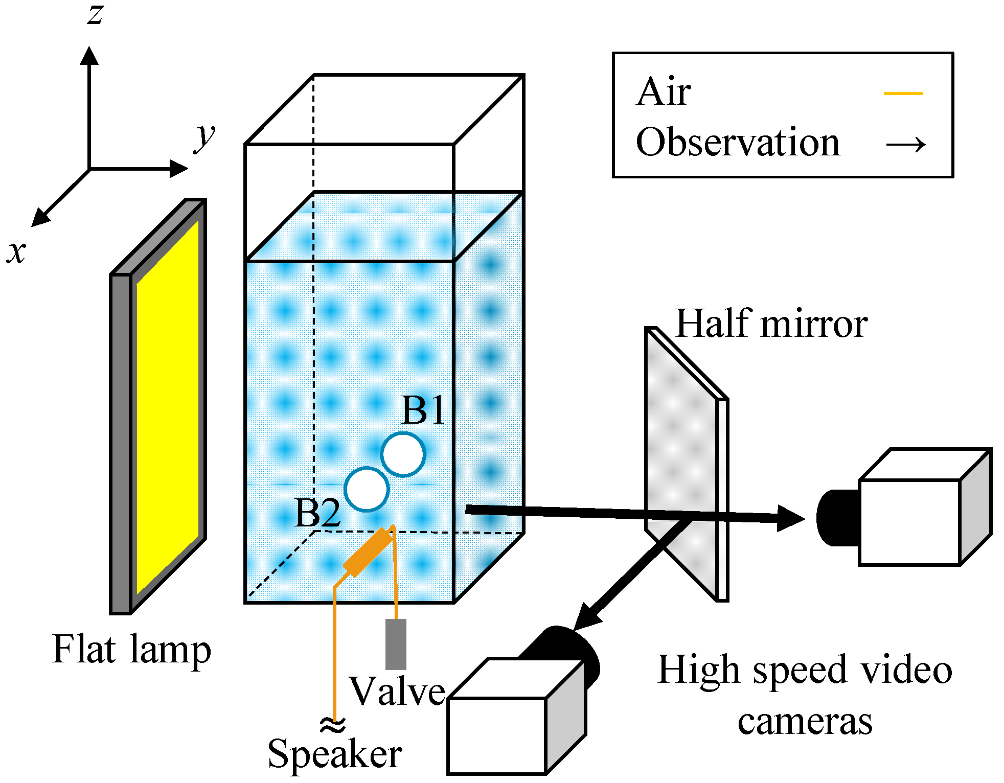
2. Experimental Methods

Figure 1 shows a schematic of the experimental setup. We referred to the bubble control system of Shirota et al. [9]. At the bottom of an acrylic vessel, we generated a pair of bubbles (B1 and B2) in a static liquid through a nylon tube with two orifices, whose diameter was 0.3 mm. We produced bubbles using an acoustic wave that reached from the speaker to the orifices. The gas was air, and the liquids were silicone oils (see in Table 1). Here, Mo = 4/ρσ3 is the Morton number. The width of a vessel was 120 mm, which is sufficient to neglect bubble–wall interaction. We used a high-speed video camera with 19 μm/pixel and 2000 fps to capture the bubble trajectories and shapes. Moreover, another high-speed video camera with 0.2 mm/pixel and 2000 fps captured the bubble trajectories in a wide range. Note here that we obtained the two bubbles migrated only on the x-z plane because the camera’s depth of field is 2 mm. The initial separation distance S normalized by the radius is 4–5.

3. Experimental Results and Discussion

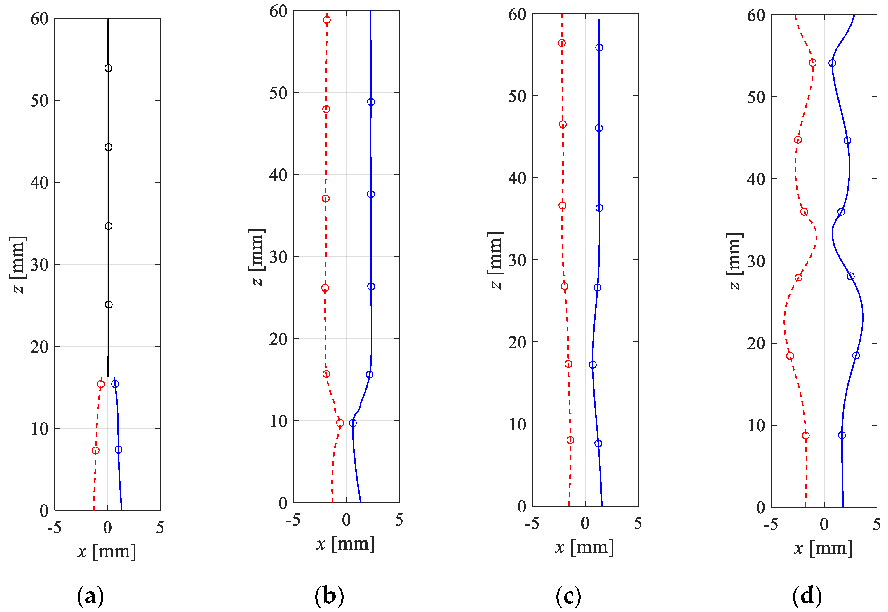
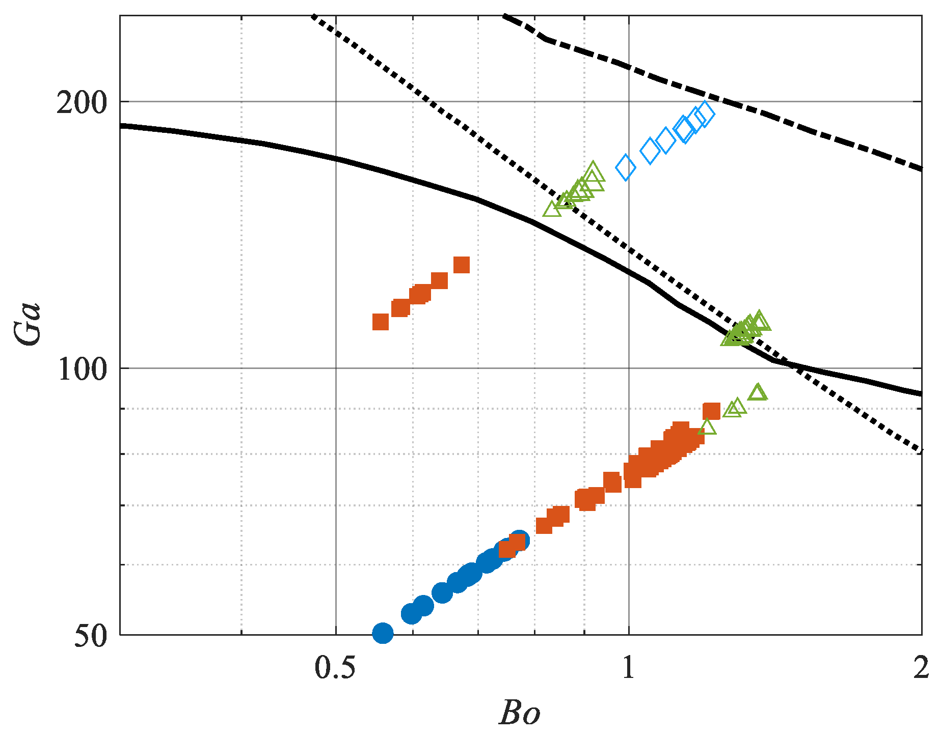
3.1. Trajectories of a Pair of Bubbles

According to experimental results of Duineveld [4] and Sanada et al. [5], a pair of bubbles rising side by side attract (resp. repel) each other with an increase (resp. decrease) in Re. However, according to recent experimental results of Yamaguchi and Sanada [6] and Kong et al. [10], large deformable bubbles repel each other even if Re is large. We firstly classify the trajectories of a pair of bubbles. Figure 2 shows typical trajectories of a pair of bubbles, and Table 2 shows the conditions. We obtained four kinds of behaviors.
M1: Attraction (decreasing S) → coalescence with kissing;
M2: Attraction → bounce with kissing;
M3: Attraction → nonkissing repulsion (increasing S);
M4: Attraction →nonkissing repulsion → repeatedly bounces with kissing.
Here, attraction indicates that in the case of M1 and M2, we obtained the same results as those in previous studies [4,5], so we provide no further details. For M3 and M4, the kissing hardly occurred in the obtained images. Figure 3 shows a series of photos in case 3E. The bubbles repelled each other even though the minimum distance between the surface was about 0.48 mm. This repulsion totally differed from the bouncing with kissing mechanism, where the thin liquid film between the bubble is important [11], because the distance between the surface of bubbles was sufficiently large.
The interactions are related to the motion of a single bubble as indicated by Tripathi et al. [7] and Zhang et al. [8]. Cano–Lozano et al. [12] provided the phase diagram of single bubble behavior in a (Ga, Bo) plane. We show the relationship between the motion of a pair of bubbles and a single bubble in Figure 4. The solid line is the critical curve for the zigzag transition of a single bubble, and the dotted line is the critical curve for the standing eddy emerging via axisymmetric simulation. The open symbols indicate kissing, and solid symbols correspond to nonkissing. We found that the kissing transition is in the vicinity of the zigzag transition curve and the standing eddy curve. Interestingly, we observed nonkissing repulsion in the rectilinear region, not only in the zigzag region. It remains unknown whether the zigzag or standing eddy is the most important factor here, but it correlates with single bubble motion. The bubbles repeatedly bounced (M4) as they progressed to the more unstable region.

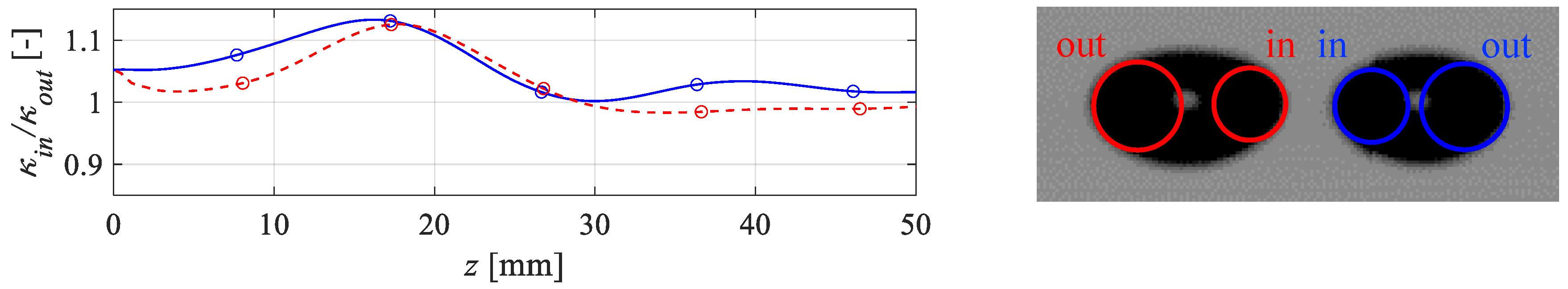
3.2. Shape of a Pair of Bubbles with Nonkissing Repulsion

We found that nonkissing repulsion of bubbles occurred in the vicinity of the zigzag transition curve and the standing eddy curve from the above results. Moreover, we observed the nonkissing repulsive behavior in the rectilinear region. Here, we consider the instability. One important factor in zigzag motion is the vorticity generated at the bubble surface. According to a discussion presented by Magnaudet and Mougin [13], who computed a fixed spheroidal bubble, the spanwise vorticity behind a bubble tends to become discontinuous in the streamwise direction with high Re, and the situation is unstable. As indicated by Cano–Lozano et al. [12], who computed paths of deformable bubbles, streamwise vorticity induces zigzag motion because it is a double-threaded wake. The vorticity has to be asymmetric to move in a zigzag manner. Both vorticities are originally generated at the bubble surface and are proportional to velocity and curvature under free shear conditions. Unfortunately, the vorticity could not be visualized in the present experiment, but we can confirm the curvature, which is an important factor of the vorticity.
Figure 5 shows the curvatures of the bubble inside the gap and outside in M3 behavior. The minimum separation distance was 0.48 mm (Figure 3). The curvature inside the gap became approximately 1.15-times larger at the minimum distance because of the interaction. According to previous studies [12,14], the double-threaded wake makes bubbles migrate toward a small curvature direction; this tendency was also observed in the present experiment, where the bubbles repelled each other. Therefore, the repulsive mechanism between bubbles may be due to instability.
Since the bubble has a curvature to balance the inside and outside interface of the normal force, the pressure with a large curvature is small. In the present experiment, the curvature inside the gap became large with nonkissing repulsion. This shows that the pressure reduced due to the narrow channel. However, the trajectories are curious considering the normal force acting on the bubble surface, because the bubbles migrated toward the higher-pressure region. We require numerical simulations for a more in-depth discussion of velocity and vorticity.

4. Numerical Methods

We considered the same situation in Section 2, namely, a pair of gravity-driven bubbles in a vessel. The computational domain was 170-times the unit diameter of bubble d (170 × 170 × 170 d) to disable the boundary effects, although we imposed no-slip on the bottom and side boundaries and a Neumann condition on the top. We used the open-source software Basilisk [15], where the VOF method is coupled with the adaptive mesh refinement method (AMR), to calculate the incompressible, variable density, and Navier–Stokes equations,
u = 0 ,
u t + ( u u ) = 1 ρ ( p + 2 μ D + σ κ δ n ) + g ,
where u is the velocity, p is the pressure, D is the deformation tensor, σ is the surface tension, δ is the Dirac distribution function, n is the unit vector normal to the interface, and g is the gravity. The interface was tracked using a geometric VOF method. The advection of the volume fraction field is written as
f t + ( f u ) = f u ,
where f is the volume fraction. The density and viscosity at each cell are calculated as a function of f
ρ = f ρ 1 + ( 1 f ) ρ 2 ,
1 μ = f μ 1 + 1 f μ 2 ,  
where ρ1, ρ2 and μ1, μ2 are the densities and viscosities of each fluid, respectively. In addition to the liquids used in the experiments, we also computed bubble motion in a more viscous liquid to obtain a broader range of information. Table 3 shows the characteristics of fluids in the present numerical simulation. The calculation was finished when the bubbles rose a distance of 30 times their diameter because of the computational cost. The initial separation distance S was 5.
The cell size Δ is important for determining the accuracy of bubble behavior. In general, high Ga (high Re) bubble simulation is difficult, because the scale of the boundary layer thickness is Re−1/2Req [16]. We previously compared the results using a boundary-fitted coordinate system [17] and determined that we needed four cells in the boundary layer. Based on their study, we set Δ = d/96 at the interface and in the wake. Note that this cell size insufficiently reproduces kissing bubble coalescence or bounce [8].
We use two coordinate systems in the discussion of numerical analysis: one was the Cartesian coordinate system shown in Figure 1, and the other was the coordinate system (r, θ, ϕ) with the center of the bubble as the origin shown in Figure 6. θ = 0 is the direction of travel, ϕ = 0 is inside the gap, and ϕ = π is outside the gap.

5. Numerical Results and Discussion

5.1. Overview of the Numerical Simulations

As in the present experiment, we classified the numerical trajectories of a pair of bubbles. Figure 7a–c show the typical trajectories of a pair of bubbles in numerical simulations. In addition, Figure 7d indicates the relationship between the motion of a pair of bubbles and a single bubble, where the lines are the same as those in Figure 4. Table 4 shows the summary of the behavior and conditions. The bubbles collided with small Ga and Bo in the range of the present study and repelled each other with large Ga and Bo. We hardly distinguish between M1 and M2 because they coalesced in kissing each other, but the target of this study is the mechanism of nonkissing repulsion.
We obtained a new behavior that no data reported in the experiment (see Figure 7c).
M5: weak attraction/repulsion, namely, the bubbles minimally migrate laterally (the increase or decrease in the separation distance is less than 0.7 in the simulation).
We obtained this new behavior in a high viscosity liquid, or even in an intermediate; however, it could not be observed in the experiment with the same conditions (cases 3E and 6N). Still, it was similar to the behavior of M2 and M3, and it may be due not only to the species of a liquid but also disturbances during bubble generation at initial separation distance.

5.2. Velocity, Curvature and Spanwise Vorticity

Legendre et al. [3] explained the mechanism of interactions between two spherical bubbles rising side by side in terms of streamwise velocity in the equatorial plane. The flow path inside the gap narrows, and the velocity increases at high Re, so the pressure decreases. In contrast, the vorticity diffusion is blocked by the other bubble at low Re, and the vorticity is tightened inside the gap with strong asymmetry. It works to reduce the velocity. Therefore, velocity is an important factor in understanding the interaction mechanism.
We extrapolated the velocity from the velocity field of the liquid to derive that of the bubble surface. Note that we needed to accurately solve for the velocity in the boundary layer to extrapolate it. We refer the reader to the results in Figure 7a–c as examples. Since the velocity profile changes from moment to moment, we show the tangential velocity us at S = 4 in Figure 8a,b and in the steady state in Figure 8c, corresponding to symbol “⋆” in Figure 7. The figures clearly show that the velocity of the equatorial plane (θπ/2) inside the gap is larger under all the conditions. The deformable bubbles repel each other even if the velocity inside the gap is larger, although the spherical bubbles attract each other because of the large velocity at high Re. Thus, the repulsion of the deformable bubbles is hardly explained only by the velocity of the equatorial plane inside the gap discussed for spherical bubbles.
On the other hand, the velocity inside the rear gap is smaller, especially the standing eddy condition in Figure 8b. This is because the vorticity generated at the bubble surface is strengthened by the interaction. Firstly, the velocity is largest inside the gap as shown in Figure 8. Next, the curvature in the θ direction κθ has the same trend as that of the velocity shown in Figure 9. Because the vorticity generated at the surface is proportional to velocity and curvature, the azimuthal vorticity ωϕ is largest inside the gap as shown in Figure 10. The vorticity decreases the tangential velocity, so the vorticity slightly affects the front where vorticity generation is minimal but strongly affects the rear where the vorticity is advected. From the above results, the dominant interactions for flow structure are as follows: (i) the velocity of the equatorial plane increases inside the gap because of the narrow channel; (ii) rear velocity inside the gap decreases because the vorticity increases with the velocity of equatorial plane inside the gap.

5.3. Streamwise Vorticity behind the Bubbles

The double-threads wake is important for various bubble lateral migrations, such as unstable migration, shear-induced lift, and wake-induced lift for inline configuration bubbles. The wake allows the existence of a lift force similar to the trailing vortices on an aircraft [18,19]. We investigated the streamwise vorticity as shown in Figure 11. We chose the different isosurface thresholds in Figure 11a–c because the absolute maximum values are different. The vorticity pair exists behind the bubble as shown in Figure 11 when bubbles attract/repel each other. Naturally, the vorticity should have a sign corresponding to the direction of lateral migration; however, the sign is the same in Figure 11a–c. The vorticity pair plays a role in repulsion regardless of whether the bubbles attract or repel each other. Therefore, we predict that the bubbles simply repel each other when the strength of the vortex pair is strengthened; otherwise, they approach each other as in the conventional potential theory.
Let us consider why the interaction causes the double-threaded wake. Since the vorticity is generated only at the bubble surface under the present study condition and is spanwise, the vorticity should become streamwise due to stretch and tilt behind the bubble. Adoua et al. [20], who computed the shear-induced lift force of a single spheroidal bubble, analyzed the contribution to the stretching/tilting term of the equation for the vorticity-neglecting viscous effect, which is
( D D t u z z ) ω z = ( ω ) u z .
The right side denotes the contribution to the stretching/tilting term due to vorticity components lying in planes perpendicular to the upstream flow. This suggests that the vorticity at the surface became streamwise due to the velocity profile of the shear flow. Based on this consideration, we investigated vorticity because of a velocity profile due to the interaction between bubbles in the present study. The right side in Equation (6) determines the sign of ωz. Since most of the vorticity generated at the surface is azimuthal vorticity, in a cylindrical coordinate system (r, ϕ, z), we focus on ωϕ, ∂uz/∂ϕ and ∂uz/∂z.
(i)
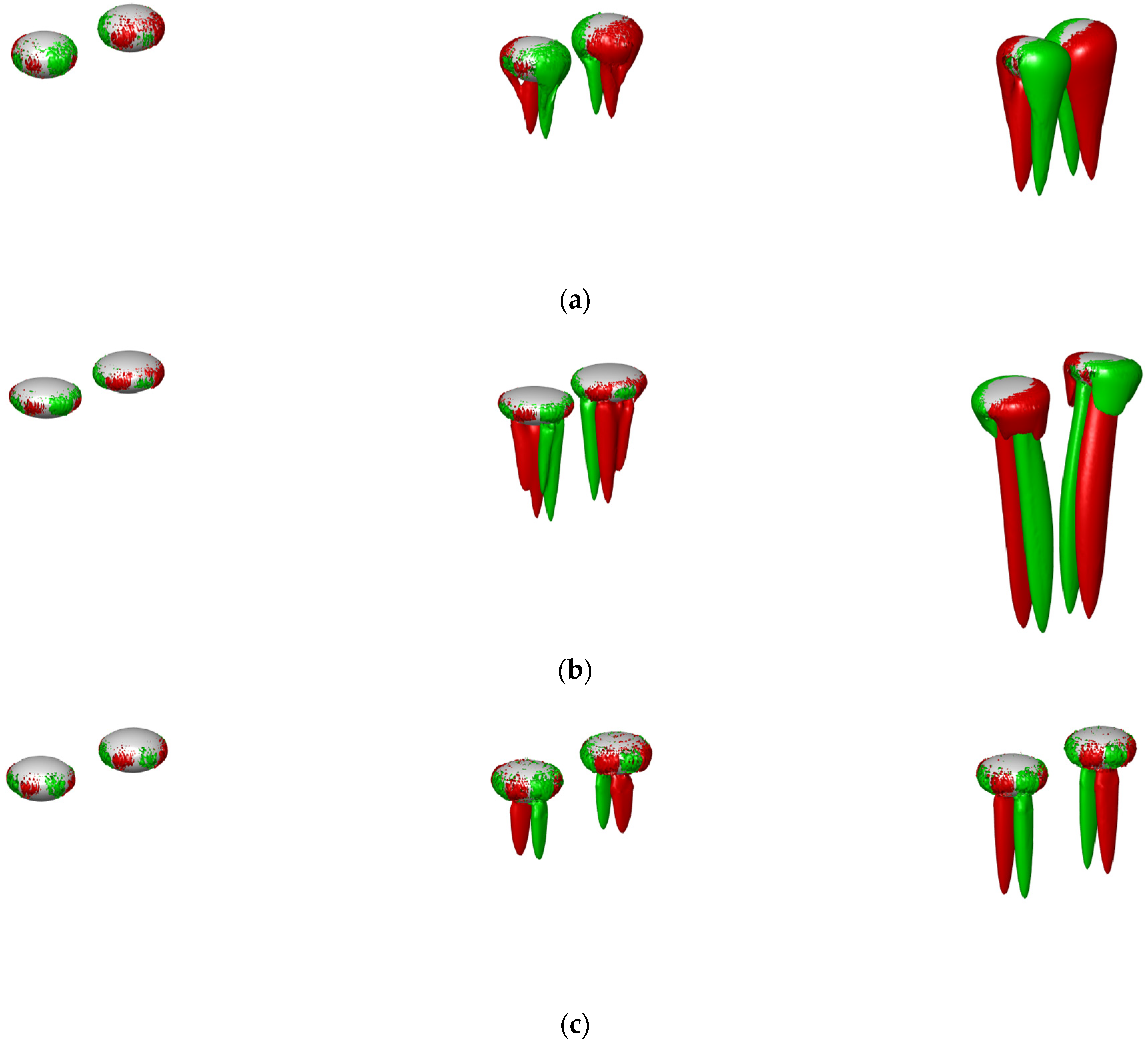
We previously obtained the spanwise vorticity at the bubble surface (Figure 10), and the vorticity sign is the same except in the rear part; however, in the rear part, it is approximately zero. The vorticity sign is the same at any azimuthal angle except in the recirculate region.
(ii)
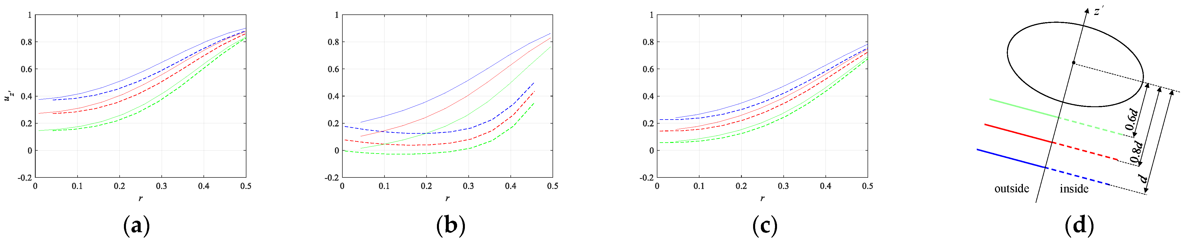
We previously obtained the velocity at the bubble surface (Figure 8); the velocity of the equatorial plane inside the gap is larger, whereas that behind the inside of the gap is smaller. Figure 12 shows the streamwise velocity profile behind the bubble where the condition is the same as that in Figure 8. Figure 12a–c shows that the streamwise velocity inside the gap behind the bubble is smaller in attracting, repelling, and holding. These velocity profiles are significant in determining the vorticity pair because ∂uz/∂ϕ is nonzero.
(iii)
As shown in Figure 12a–c, the streamwise velocity gradient ∂uz/∂z has the same sign.
The sign of streamwise vorticity is determined from (i–iii) above. The streamwise vorticity should play a role in repelling when the streamwise velocity inside the gap is larger. In fact, the velocity of the equatorial plane inside the gap is larger, but that behind it is smaller, so we predict that the velocity gradient of the equatorial plane will mostly affect the vorticity stretching/tilting term, but this is difficult to judge and beyond the scope of the current study.

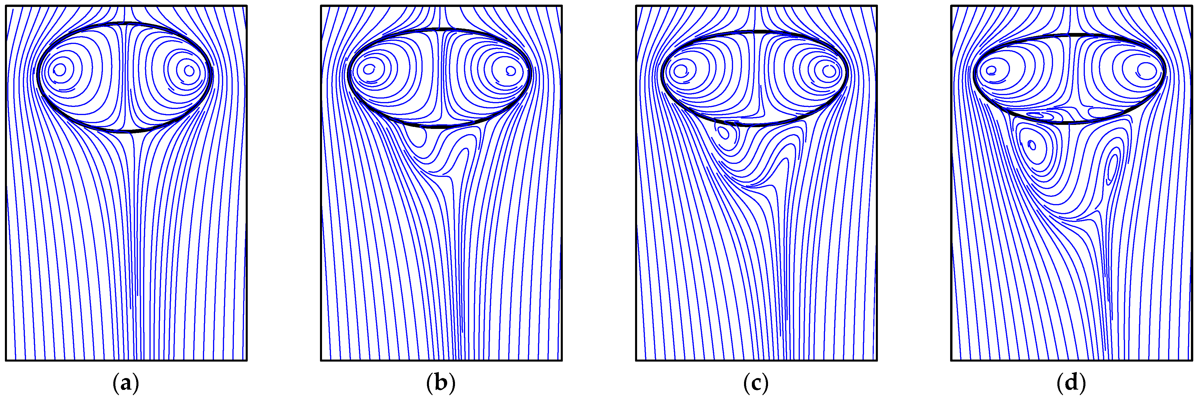
5.4. Streamline on x-z Plane and Lift

From the above discussion, the traveling direction of the bubble should change due to the double-threaded wake, which changes the direction of flow. Here, we investigate streamlines around the bubble (but in 2D). Figure 13 shows the streamline around the bubble on the x-z plane. From Figure 13a, it can be observed that the downstream streamline looks undisturbed in attracting (M1 and M2), and the variation in flow direction is from the outside to the inside. In contrast, from Figure 13b,c, the downstream streamline looks disturbed in repelling (M3 and M4), and a more visible variation in the flow direction from the outside to the inside can be seen. These results and corresponding behaviors are similar to those discussed by Zhang et al. [8].
Figure 14 shows the streamline when bubbles rise in liquid K5. The condition in Figure 14a–c is weak repulsion, and that in Figure 14d is repulsion. Although we observed no toroidal vortex in Figure 14a, one could be seen in Figure 14b–d. Zhang et al. [8] suggested that weak repulsion occurs due to the toroidal vortex squeeze. Figure 14a, where the Re is approximately 73, indicates that the bubbles repel each other even if there is no toroidal vortex, and the bubbles approach each other at any distance using the analytical equation (Equation (7)) for the spherical bubble. In Figure 14b–d, the toroidal vortex certainly squeezed, and the behavior is also weak repulsion. The presence or absence of toroidal vortices and the behavior of bubbles are inconsistent.
As indicated by Legendre et al. [3], the lift coefficient of spherical bubbles rising side by side is estimated as
C L 6 S 4 ( 1 40 R e ) + ,
where the first term is the potential effects, and the second term is the viscous effects. They determined that the first term corresponds to the velocity induced by the other bubble. This asymmetry affects the second term corresponding to the pressure correction associated with the vortical velocity. The vorticity generated at the spheroidal bubble is O(χ8/3) and the velocity is O(χ) [13], so its effect may increase the repulsive force compared with that of the spherical bubble. The asymmetry pressure profile due to the vorticity may cause the deformable bubble’s repulsion in the rectilinear region. However, it is difficult to uniquely determine the repulsion mechanism.

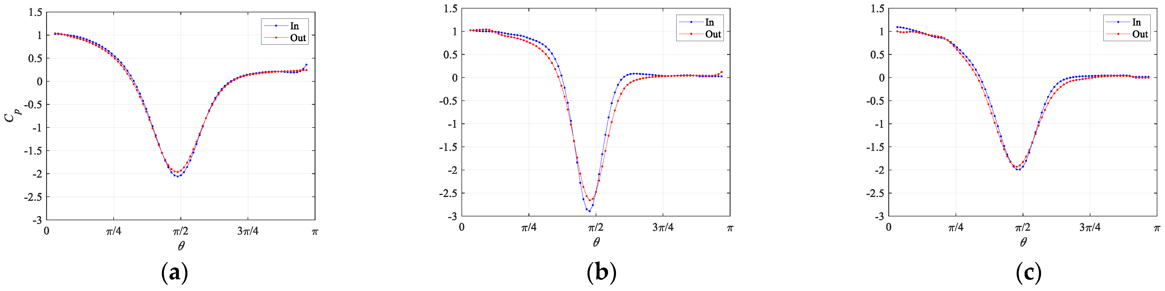
5.5. Pressure at the Bubble Surface

We also estimated the pressure at the bubble surface since the dominant factor of lift is pressure. Figure 15 shows the pressure coefficient at the bubble surface. Repeatedly, we extrapolated the pressure from the pressure field of the liquid to derive that of the bubble surface. Figure 15 clearly shows that the pressure corresponds to the velocity in Figure 8. Thus, the pressure of the equatorial plane inside the gap is smaller regardless of the behaviors, and the pressure recovery inside the gap is earlier because the strong vorticity strengthens flow separation. Considering the normal force parallel to the x-axis, all bubbles appear to attract each other, but the present results clearly suggest that this is not true.
It seems that it is difficult to extract the lift mechanism from the pressure distribution using the fixed grids with moving bubbles because the asymmetry interaction is weak and a bubble feels the added mass force, which implicitly includes the pressure, just by accelerating. Thus, a numerical analysis of fixed bubbles under a nonaccelerating condition is required to investigate the pressure mechanism of this repulsion.

6. Summary and Conclusions

We experimentally and numerically investigated the interaction mechanism of two bubbles rising side by side in a stationary liquid. We focused on the nonkissing repulsion phenomenon.
In the experiment, we confirmed nonkissing repulsion organized by the Ga-Bo map. As the deformation of the bubbles increased, the bubbles repelled each other without kissing. This repulsion was observed in the zigzag region. Since the deformation was uniquely determined by the interaction between bubbles, the zigzag motion of bubbles was limited to the same plane. Repulsion was also observed in the linearly rising region (however, near the zigzag region). Instability may be induced because the interaction increases the curvature inside the gap.
In the numerical analysis, we confirmed nonkissing repulsion and weak attraction/repulsion organized by the Ga-Bo map. We investigated the flow structure of these various behaviors. In both cases, the velocity of the equatorial plane inside the gap at the surface was larger. In addition, the spanwise vorticity and curvature also increased. Since this vorticity played the role of reducing the streamwise velocity, the velocity inside the gap behind the bubble was smaller. The spanwise vorticity generated at the bubble surface by this velocity distribution became the streamwise vorticity due to stretch and tilt. The double-threaded wake behind the bubble played a role in repelling.
From the streamline, we confirmed that the direction of flow clearly changed in the zigzag region. The repulsion of bubbles was similar to the zigzag behavior (see Zhang et al. [8] for details). In the rectilinear region, the direction of the flow was from the outside to the inside. The presence or absence of toroidal vortices and the behavior of bubbles were inconsistent. Numerical analysis with fixed spheroidal bubbles is required for a more in-depth discussion of pressure profiles.

Author Contributions

Conceptualization, H.K. and T.S.; methodology, H.K. and T.S.; investigation, H.K. and T.S.; data curation, H.K.; visualization, H.K.; writing—original draft, H.K. and T.S. All authors have read and agreed to the published version of the manuscript.

Funding

This work was supported by JSPS KAKENHI, Grant No. JP2013337. The financial support is gratefully acknowledged.

Institutional Review Board Statement

Not applicable.

Informed Consent Statement

Not applicable.

Data Availability Statement

All numerical data are available upon reasonable request from the correspond authors via email.

Acknowledgments

We wish to thank Eri Yamaguchi for help in the experiment.

Conflicts of Interest

The authors declare no conflict of interest.

References

  1. Haas, T.; Schubert, C.; Eickhoff, M.; Pfeifer, H. A Review of Bubble Dynamics in Liquid Metals. Metals 2021, 11, 664. [Google Scholar] [CrossRef]
  2. Takagi, S.; Matsumoto, Y. Surfactant effects on bubble motion and bubbly flows. Annu. Rev. Fluid Mech. 2011, 43, 615–636. [Google Scholar] [CrossRef]
  3. Legendre, D.; Magnaudet, J.; Mougin, G. Hydrodynamic interactions between two spherical bubbles rising side by side in a viscous liquid. J. Fluid Mech. 2003, 497, 133–166. [Google Scholar] [CrossRef]
  4. Duineveld, P.C. Bouncing and coalescence of bubble pairs rising at high Reynolds number in pure water or aqueous surfactant solutions. In Fascination of Fluid Dynamics; Springer: Dordrecht, The Netherlands, 1998; pp. 409–439. [Google Scholar]
  5. Sanada, T.; Sato, A.; Shirota, M.; Watanabe, M. Motion and coalescence of a pair of bubbles rising side by side. Chem. Eng. Sci. 2009, 64, 2659–2671. [Google Scholar] [CrossRef] [Green Version]
  6. Yamaguchi, E.; Sanada, T. Bouncing of a pair of clean bubbles rising side by side. In Proceedings of the Ninth JSME-KSME Thermal and Fluids Engineering Conference, Ginowan City, Japan, 27–30 October 2017. [Google Scholar]
  7. Tripathi, M.K.; Premlata, A.R.; Sahu, K.C.; Govindarajan, R. Two initially spherical bubbles rising in quiescent liquid. Phys. Rev. Fluids 2017, 2, 073601. [Google Scholar] [CrossRef] [Green Version]
  8. Zhang, J.; Chen, L.; Ni, M.J. Vortex interactions between a pair of bubbles rising side by side in ordinary viscous liquids. Phys. Rev. Fluids 2019, 4, 043604. [Google Scholar] [CrossRef]
  9. Shirota, M.; Sanada, T.; Sato, A.; Watanabe, M. Formation of a submillimeter bubble from an orifice using pulsed acoustic pressure waves in gas phase. Phys. Fluids 2008, 20, 043301. [Google Scholar] [CrossRef]
  10. Kong, G.; Mirsandi, H.; Buist, K.A.; Peters, E.A.J.F.; Baltussen, M.W.; Kuipers, J.A.M. Hydrodynamic interaction of bubbles rising side-by-side in viscous liquids. Exp. Fluids 2019, 60, 1–15. [Google Scholar] [CrossRef] [Green Version]
  11. Chesters, A.K.; Hofman, G. Bubble coalescence in pure liquids. In Mechanics and Physics of Bubbles in Liquids; Springer: Dordrecht, The Netherlands, 1982; pp. 353–361. [Google Scholar]
  12. Cano-Lozano, J.C.; Martinez-Bazan, C.; Magnaudet, J.; Tchoufag, J. Paths and wakes of deformable nearly spheroidal rising bubbles close to the transition to path instability. Phys. Rev. Fluids 2016, 1, 053604. [Google Scholar] [CrossRef] [Green Version]
  13. Magnaudet, J.; Mougin, G. Wake instability of a fixed spheroidal bubble. J. Fluid Mech. 2007, 572, 311–337. [Google Scholar] [CrossRef]
  14. Zhang, J.; Ni, M.J. What happens to the vortex structures when the rising bubble transits from zigzag to spiral? J. Fluid Mech. 2017, 828, 353–373. [Google Scholar] [CrossRef]
  15. Popinet, S. Basilisk. Available online: https://basilisk.fr (accessed on 7 September 2021).
  16. Blanco, A.; Magnaudet, J. The structure of the axisymmetric high-Reynolds number flow around an ellipsoidal bubble of fixed shape. Phys. Fluids 1995, 7, 1265–1274. [Google Scholar] [CrossRef]
  17. Kusuno, H.; Sanada, T. Velocity distribution in the boundary layer of a bubble rising with a rectilinear motion. Trans. JSME 2020, 86, 19-00453. [Google Scholar] [CrossRef]
  18. Shew, W.L.; Poncet, S.; Pinton, J.F. Force measurements on rising bubbles. J. Fluid Mech. 2006, 569, 51–60. [Google Scholar] [CrossRef] [Green Version]
  19. Harper, J.F. Bubbles rising in line: Champagne, lager, cider. In Bubbles in Food 2; AACC International Press: Washington, DC, USA, 2008; pp. 147–152. [Google Scholar]
  20. Adoua, R.; Legendre, D.; Magnaudet, J. Reversal of the lift force on an oblate bubble in a weakly viscous linear shear flow. J. Fluid Mech. 2009, 628, 23–41. [Google Scholar] [CrossRef] [Green Version]
Figure 1. Schematic of experimental setup.
Fluids 06 00390 g001
Figure 2. Trajectories of pair of bubbles. Solid line: trajectory of B1; dashed line: trajectory of B2; symbol “o”: location every 50 ms. (a) Case 1E; (b) case 2E; (c) case 3E; (d) case 4E.
Fluids 06 00390 g002
Figure 3. A nonkissing repulsive motion of a pair of bubbles in case 3E.
Fluids 06 00390 g003
Figure 4. Phase diagram of a single bubble’s behavior (Cano–Lozano et al., 2016) and a pair of bubbles’ behaviors in the (Ga, Bo) plane. Solid line: critical curve for zigzag transition of a single bubble. Dotted line: critical curve for the standing eddy emerging via axisymmetric simulation. ●: M1. ■: M2. △: M3. ♢: M4.
Fluids 06 00390 g004
Figure 5. Curvature ratio between inside and outside the gap. Solid line: B1; dashed line: B2; symbol “o”: curvature ratio every 50 ms.
Fluids 06 00390 g005
Figure 6. Coordinate system (r, θ, ϕ) and (r, ϕ, z’) where origin is center of a bubble.
Fluids 06 00390 g006
Figure 7. Trajectories of pair of bubbles (ac), phase diagram of single bubble behavior (Cano–Lozano et al., 2016), and a pair of bubbles’ behavior in (Ga, Bo) plane (d). (a) Case 2N; (b) case 4N; (c) case 6N; symbols: ⋆: typical time in Figure 8, Figure 9 and Figure 10; (d) ■: M1/M2; △: M3; ♢: M4; ▽: M5.
Fluids 06 00390 g007
Figure 8. Velocity at bubble surface: (ac) are under same conditions as those in Figure 7. (a) S = 4; (b) S = 4; (c) steady. Velocity inside gap in equatorial plane is larger. However, rear velocity inside gap is smaller.
Fluids 06 00390 g008
Figure 9. Curvature at bubble surface: (ac) are under same conditions as those in Figure 8.
Fluids 06 00390 g009
Figure 10. Azimuthal vorticity at bubble surface: (ac) are under same conditions as in Figure 8.
Fluids 06 00390 g010
Figure 11. Streamwise vorticity of interacting bubbles: behavior is (a) attracting bubbles, (b) repelling bubbles, and (c) weak repelling bubbles. Green and red vorticity isosurfaces are (a) ωz = ±0.15, (b) ωz = ±0.3 and (c) ωz = ±0.1. Double-threaded wakes are behind bubbles, and trend is same in all conditions.
Fluids 06 00390 g011
Figure 12. Streamwise velocity behind bubble: (ac) are under same conditions as in Figure 8. (d) Legend description for (ac). Solid line: outside velocity. Dashed line: inside velocity. Green lines indicate 0.6d behind center of bubble, red ones 0.8d, and blue ones 1d.
Fluids 06 00390 g012
Figure 13. Streamlines (uU) in x-z plane: right side is inside gap. (ac) are under same conditions as in Figure 8. Flow direction behind bubble is from outside to inside.
Fluids 06 00390 g013
Figure 14. Streamlines (uU) in x-z plane: right side is inside gap. (a) Case 8N (b), case 9N (c), case 10N (d), case 11N. Flow direction behind bubble is from outside to inside.
Fluids 06 00390 g014
Figure 15. Pressure profiles at bubble surface: (ac) are under same conditions as in Figure 8.
Fluids 06 00390 g015
Table 1. Characteristics of liquids in present experiment.
Liquidμ [mPa⋅s]ρ [kg/m3]σ [mN/m]Mo
K10.881816.91.1 × 10−9
K21.787318.31.7 × 10−8
Table 2. Typical trajectories of a pair of bubbles and conditions in experiment.
CaseGaBoMoTrajectorySingle TrajectoryTrajectory after Repulsion
1E710.91.7 × 10−8M1rectilinear-
2E1170.61.1 × 10−9M2rectilinearrectilinear
3E901.31.7 × 10−8M3rectilinearrectilinear
4E1861.11.1 × 10−9M4zigzagrepeated bounce
Table 3. Characteristics of fluids in present computation.
Fluidμ [mPas]ρ [kg/m3]σ [mN/m]Mo
K10.881816.91.1 × 10−9
K21.787318.31.7 × 10−8
K54.691519.76.1 × 10−7
Air0.0181.2--
Table 4. Trajectories of a pair of bubbles and conditions in the numerical simulation.
CaseGaBoMoTrajectorySingle TrajectoryTrajectory after Repulsion
1N900.41.1 × 10−9M1/M2rectilinear-
2N1170.61.1 × 10−9M1/M2rectilinear-
3N1570.91.1 × 10−9M3zigzagzigzag
4N1861.11.1 × 10−9M4zigzagzigzag
5N710.91.7 × 10−8M1/M2rectilinear-
6N901.31.7 × 10−8M5rectilinear-
7N1001.71.7 × 10−8M3zigzagzigzag
8N582.26.1 × 10−7M5rectilinear-
9N723.06.1 × 10−7M5rectilinear-
10N803.46.1 × 10−7M5rectilinear-
11N903.76.1 × 10−7M3zigzagzigzag
Publisher’s Note: MDPI stays neutral with regard to jurisdictional claims in published maps and institutional affiliations.

