1. Introduction
The problem of high-speed flow control using non-mechanical approaches, and remote energy deposition in particular, currently occupies a leading place among the problems in flow/flight control [
1]. Control of supersonic flows by means of electrical discharges, microwave and laser impulses is currently a well-developed area of aerospace engineering (see surveys in [
2,
3,
4]). A historical review of the ideas pertaining to the control of supersonic flow by energy deposition to different points of the flow, which arose several decades ago, was presented in [
5]. In a significant number of studies, the effectiveness of energy supply in the form of extended filaments (“hot spikes”) was established for reducing aerodynamic drag [
6,
7,
8]. In air, the effect of microwave discharge was determined by a decrease in stagnation pressure, along with the reduction of a drag force of a blunt cylinder. In the calculations, a vortex mechanism of these phenomena was established [
9]. In [
10], the curvature of the shock wave was observed during the passage through the region of a plasma zone created by longitudinal pulsed discharge.
The influence of inhomogeneous layered plasma on a reflected shock wave in a supersonic flow was studied in [
11]. In these experiments, the blurring and suppression of the reflected shock wave were obtained due to the organization of a system of plasma filaments created by a high-frequency discharge [
12,
13]. In [
14], an array of surface arc plasma actuators were used to control the interaction of the shock wave with the boundary layer in a flow with Mach number 2. As a result, the disappearance of a fragment of the separation shock wave was established. In [
15], the authors used a set of heated thin wires for the creation of thermal and density inhomogeneities, which led to the generation of the Richtmyer-Meshkov instability and the formation of a line of vortices due to the Kelvin-Helmholtz instability.
The impact of the ionization strata obtained in the gas discharge plasma region on a plane shock wave was researched in [
16]. These experiments attained the curvature, and in some cases, complete disappearance of the shock wave front. In the numerical simulation of the experiment, generation in many points of the Richtmyer-Meshkov instabilities was shown under the action of which the shock wave front (in density field) practically ceased to exist, which explained the results of the experiment [
16].
In [
17,
18], the vortex structure was obtained under the action of a combined energy source, and a double-vortex mechanism of its action on the body was proposed, explaining the additional decrease in the front drag force. It was shown that the generation of the vortices is a result of the manifestation of the Richtmyer-Meshkov instability. A thermally stratified energy source was shown to initiate multiple generation of the Richtmyer-Meshkov instabilities during the interaction with the shock wave front, causing significant density and temperature fluctuations [
19]. The redistribution of energy types in a curved shock wave under the conditions of the experiment [
16] was estimated for M = 2 and 5 [
20], and for hypersonic speeds up to M = 12 [
21]. In addition, the influence of a thermally stratified energy source on the supersonic flow around an AD body was investigated, and a new multi-vortex mechanism of the action of the energy source on the body surface has been established [
22].
This study focuses on the development of a thermally stratified energy source impacting the flow around supersonic AD bodies in a viscous heat-conducting gas (air). The paper focuses on an unsteady temporary action of a thermally stratified energy source. The research is based on the system of Navier-Stokes equations. The freestream Mach number is 2. Almost complete destruction of the bow shock wave in the density field, through the multiple generation of the Richtmyer-Meshkov instabilities in the region of heated layers of a stratified energy source, is obtained. The dependences of drag and lift (pitch) forces of a streamlined body on temperature in the layers of a stratified energy source are studied. The temperature values in the layers are analyzed and show the possibility of influencing the drag force and the ability to cause the formation and change of the lifting (pitch) force (at zero angle of attack). The main principles of flow control using a stratified energy source are established.
2. Methodology and Statement of the Problem
The impact of a thermally stratified energy source on a supersonic flow past a plate sharpened by a wedge is considered. The angle at the apex of the body is 90° (
Figure 1).
The simulations are based on the Navier-Stokes equations for perfect viscous heat conductive gas (air); the ratio of specific heats
γ = 1.4. The full Navier-Stokes system of equations in the divergent form for the dimensionless variables [
23] is solved numerically:
Here,
ε is the specific internal energy. The following normalizing values for the parameters are accepted:
where
kl is the dimensionless value of
D. The freestream Mach number is M
∞ = 2, the Reynolds number is Re = 9500, and the Prandtl number is Pr = 0.703.
Sutherland’s law in nondimensional form is used for the dependence of dynamic viscosity on temperature:
s1 = 0.409556 (120 K). The coefficient of heat conductivity
k is supposed to depend on temperature in nondimensional form as follows:
Initial conditions for the problem are the fields of gas parameters in a steady supersonic flow past the body,
t = 0.6. At this time, the pressure and density at the apex of the body differ from their theoretical values evaluated with the use of the Bernoulli’s relation by 1.81% and 1.75%, respectively. Here, the converging criterion for the evaluation of the relative errors is used in a form:
where
ft and
ft theor are the calculated value at the apex of the body and the theoretical one evaluated from the Bernoulli’s relation.
The boundary conditions provide no-slip conditions for the adiabatic wall at the horizontal boundaries and at the wedge boundaries, and establish the absence of according normal flows on the boundaries of the body:
At the exit boundaries of the computation domain, the absence of reflection in the normal directions is set as follows:
The stratified energy source is modeled by a region of rarefied gas layers of the same width located ahead of the bow shock wave front in its immediate vicinity (see
Figure 1). The distances between the layers were equal to half the width of the layer. Inside the layers (indicated by the index
j), gas density was applied to be reduced,
N is a number of layers in the energy source. The pressure and velocity in the domain of the energy source are set equal to their values in the oncoming flow (indicated by the index ∞),
Therefore, the temperature inside the layers is increased compared to its value in the oncoming flow,
Thus, a stratified energy source is specified by a set of rarefaction parameters {αj} = α1, α2, … αN in its layers. The axis of symmetry of the stratified source is supposed to coincide with the axis of symmetry of the body. The energy source arises instantly in the steady flow at the time instant ti, and it is assumed that it has a limited duration in time.
A domestic code based on the complex conservative difference schemes of the second order of approximation in space and in time is used in the simulations. Details of construction of the schemes in the computational domain and in the vicinity of the body’s boundaries, are presented in [
24]. For increasing the order of approximation in the development of the schemes, the differential consequences of system (1) for the spatial derivatives on
x and
y are used. The five-point stencil (the stencil of Lax’s scheme) is applied for the scheme construction; therefore the grids used are staggered and uniform everywhere in the computational domain.
The boundaries of a body are introduced into the calculation area without breaking the conservation laws in it (in space and time). For this purpose, the boundaries of the body are included to a structural staggered orthogonal grid, and discrete conservation laws are written for each arising grid configuration. Thus, the schemes are written for 1/4 of a difference cell, 1/2 of a cell and 3/4 of a cell, and are used, as necessary, in accordance with the position of the body’s boundary on the difference grid. In this case, the reflected versions of the schemes are possible, as well as schemes on half cells in the
x- and
y- directions. This allows the carrying out of calculations conservatively in the entire computational domain, including the regions adjacent to the boundaries of the body [
24].
The position of the sharpened part of the body on the grid in an enlarged form is shown in
Figure 2. In the calculations, the staggered numerical grids are used with the distance between the nodes at each time level equal to 2
hx, 2
hy (
hx,
hy are the space steps in
x- and
y-directions). To select the time step, the Courant-Friedrichs-Levy criterion are used.
The numerous test examples for the used numerical methods and developed software are presented in [
24]. Comparison with the experimental results was conducted in [
25]. Nevertheless, we present some test case analysis below.
3. Method Validation and Grid Convergence Analysis
Figure 3 demonstrates the analysis of the possibilities of the applied numerical code for the resolution of shock waves and contact surfaces (shear layers). The “quasi-one-dimensional” Riemann problem of the decay of an arbitrary discontinuity was chosen for validation. The statement of the problem is schematically shown in
Figure 3a. At the initial moment of time
t = 0, a heated gas region is set with the rarefaction parameter of
α = 0.5 at 0 <
x < 1.45, and a plane shock wave with the Mach number of 2 at the point with
x = 1.55. At
t > 0, the shock wave begins to move from right to left, and at time
t = 0.04226 the shock wave begins to interact with the boundary of the heated region at the point with
x = 1.45. The emerging flow in the inviscid case is described by the Riemann problem with the formation of a shock wave and a contact discontinuity moving from right to left (and a rarefaction wave propagating to the right) [
26]. The numerical density profiles at the axis of symmetry are presented in
Figure 3b. Comparison of the locations of shock fronts at different times with the analytical solution (dashed lines) shows a high computational accuracy of the used difference schemes.
For the analysis of grid convergence, the calculations of flow dynamics during the steady state establishment for three difference grids were conducted (
Table 1,
t = 0.6). The characteristics of these grids are presented, as well as the relative errors for the stagnation parameters at the apex of the body, in comparison with the theoretically obtained ones from the Bernoulli’s relation.
Figure 4 demonstrates the flow fields in isochores (
Figure 4a) and the dynamics of the parameters at the stagnation point (
Figure 4b) obtained using these three difference grids. The number of nodes of Grid1 and Grid3 differ by 16 times, and the number of nodes of Grid1 and Grid2 by four times, but nevertheless, one can see that the values at the apex of the body differ from their theoretical values less than by 2% (for Grid1). Additionally, the positions and shapes of the bow shock waves almost coincide (see
Figure 4a).
Therefore, all these factors show that grid convergence has taken place. For the simulations, we use Grid1 (hx = hy = 0.0005) on two computation domains which contain 9.52 × 10⁶ nodes (3400 × 2800, coordinate of the body’s axis of symmetry y0 = 0.7) and 12.96 × 10⁶ nodes (3600 × 3600, y0 = 0.9). Here, the dimensions of the grids are specified counting the middle node of the stencil.
4. Results
The defining flow parameters used in the simulations are presented in
Table 2. The energy source specified, as described above, is supposed to instantly arise in the steady flow at the time
ti = 0.601 moves together with the oncoming flow and begins to interact with the bow shock wave. The dynamics of the density fields following this interaction for different symmetrical sets of the values of
αj in the layers of the energy source is presented in
Figure 5. Here, the results of two series of the calculations are presented, with sets {
αj} with a heated central layer
α3, and sets {
αj} with the additional layers of reduced density
α2 and
α4.
The first and second lines of images demonstrate the dynamic of the originated vortex structures, which are caused by the sets of layers {αj} with a heated central layer. One can see the dynamic of a complicated shock structure with two vortices with the decreased density accompanying the Richtmyer-Meshkov instability. The front of the bow shock wave undergoes a significant transformation. As the stratified region of the energy source passes, the diffraction of the shock wave occurs, accompanied by the formation of two symmetrical triple configurations (t = 0.85). During the passage of the stratified pulse, one can see the curvature of the bow shock wave (t = 1.05), which is greater the smaller the value of α3 (or the higher temperature) in the central layer. After the passage of the stratified pulse, the flow returns to the undisturbed steady mode. These results are consistent with the results of numerous studies on the effect of a heated longitudinal region on a bow shock wave.
Images on other lines in
Figure 5 correspond to sets {
αj} with the additional layers of reduced density
α2 and
α4. In this case, the formation of additional vortices and more complex shock-wave structures is seen (
t = 0.85, 1.05). The bending of the bow shock wave is almost rectilinear in the source zone. After passing the stratified region, the bending of the bow shock wave is also noticeable, which is greater the lower the values of
αj in the source layers (
t = 1.25); at the end of the interaction process, the flow returns to the undisturbed steady flow mode.
The dynamics of the density fields in surface view is presented in
Figure 6. One can see the blurring of the front of the bow shock wave under the action of thermal layers, and for the given several heated layers in the energy source, the front of the bow shock wave practically ceases to exist. This occurs under the influence of the development of multiple Richtmyer-Meshkov instabilities [
17,
22], which are characterized by the appearance of sharp fluctuations (peaks) of parameters and the formation of the accompanying “mushroom” structures.
The corresponding dynamics of the pressure fields is presented in
Figure 7. Since, in the layers of the stratified source, pressure is equal to the freestream pressure, the source layers are not visible in the pressure field. It can be seen that at the beginning of the interaction, the front of the bow shock wave becomes wavy (
Figure 7; the fourth and fifth lines of images,
t = 0.75). Further, it is deformed, and after the passage of the stratified impulse, the flow comes to an unperturbed stationary state. It can also be seen that inside the formed vortices, the pressure, as well as the density, is reduced (
Figure 7 1st line of images,
t = 1.05 and
t = 1.25).
The dynamics of the temperature fields are presented in
Figure 8. One can see that the action of the stratified energy source causes complicated temperature structures inside the shock layer. Temperature fluctuations with high-temperature values (approximately four times higher than the temperature of the oncoming flow) are visible inside the resulting vortex structures (
t = 0.85, 1.05). Temperature fluctuations are stronger for hotter layers, and for more number of heated layers in the energy source (third line of the images,
t = 1.05); however, these can be expected.
The dynamics of drag force for different symmetrical sets {
αj} are presented in
Figure 9. It is seen that the drag force reduction is greater for more rarefied layers in the energy source (with a greater temperature) (
Figure 9a). The addition of the heated layers to the stratified source adds oscillation to the drag force dynamic, increasing the time interval on which the drag force is decreased (
Figure 9b). Drag reduction is greater (and the longer action in time) the more layers are in the source with the reduced values of
αj (or higher temperatures) in the layers. Thus, it is possible to control the drag force of an AD body surface by changing the temperature values and the number of heated layers in a thermally stratified energy source. Note, that in this case, for symmetrical sets {
αj} in the source, lift forces do not arise, in contrast to asymmetric sets {
αj} in the source, as will be shown below.
The dynamics of the density fields for different asymmetric sets {
αj} in the stratified energy source are presented in
Figure 10. One can see the initiation of the asymmetric vortex structures; the drop in densities in these vortices is greater for smaller values of
αj (
t = 0.75, 0.85). On hotter layers, the bow shock wave diffracts with the formation of asymmetric triple shock configurations (
t = 0.85). After the passage of the stratified pulse, the instabilities weaken, and the front of the bow shock wave is restored, retaining the asymmetric shape (
t = 1.05). Furthermore, the shape of the bow shock wave approaches the body and its shape becomes close to symmetrical (
t = 1.25). At the end of the process, when the impulse leaves the computational area, the flow returns to its original unperturbed state. Comparing the flow patterns for different sets of {
αj} presented in
Figure 10, we can conclude that the drops in densities in the resulting vortices are larger for smaller values of
αj (see the third row of images). In addition, for smaller values of
αj, the action of resulting vortex structures on the lower body surface is stronger for smaller values of
αj, or larger the values of temperature in the layers (see the fourth row).
In
Figure 11, the fields of density for asymmetric sets {
αj} are presented. Here, asymmetric (left row of images) and “reflected” asymmetric (right row of images) sets {
αj} are considered; where, in asymmetric sets {
αj} = (
α1,
α2,
α3,
α4,
α5) and in “reflected” asymmetric sets {
αj} = (
α5,
α4,
α3,
α2,
α1). In addition, the structure of the flow is demonstrated by the vector fields of the flow velocity
U = (
u,
v). It is seen that inside the vortex structures the flow is circular. The corresponding flow patterns obtained are directly opposite, which is due to the coincidence of the symmetry axes of the energy source and the body, i.e., it is assumed that the source is rigidly installed symmetrically with respect to the AD body.
The dynamics of unsteady drag forces for different asymmetric sets {
αj} in the stratified energy source are presented in
Figure 12. We consider the drag force formed by the wedge part of the body
Fdrag, and the drag forces formed by the top and bottom surfaces of the wedge,
Fdragtop and
Fdragbottom. It can be seen that, as in the case of symmetrical sets {
αj}, the drops in drag force
Fdrag are greater for smaller
αj (compare the green, orange and blue curves); here, the rate of change in drag is almost the same. However, using the layers with different
αj, it is possible to set a different rate of change in the drag force, which is greater the greater the difference in
αj (in the temperature values) in the layers (see green, purple and olive curves). One can also see that for asymmetric and “reflected” asymmetric sets {
αj} the drag forces of top and bottom surfaces are of the opposite values, and the total drag forces are the same. This is connected with the fact that the axis of symmetry of the stratified source is supposed to coincide with the axis of symmetry of the body.
In
Figure 13 and
Figure 14, the dynamics of unsteady lift (pitch) forces for different asymmetric sets {
αj} in the stratified energy source are presented. We consider the lift force formed by the wedge part of the body
Fliftwedge, the lift force formed by the horizontal surfaces of the body
Flifthorizontal, and the total lift force of the body
Flifttotal. The dynamics of lift forces
Fliftwedge and
Flifthorizontal, for asymmetric and “reflected” asymmetric sets {
αj}, are shown in
Figure 13a,b, accordingly. It can be seen that the lift (pitch) forces are defined mostly by the wedge part of the body
Fliftwedge, and the absolute value of these forces are greater for the sets {
αj} with the more rarefied layers (compare green, orange and blue curves).
Additionally, it is possible to control the rate of change of the lift force Fliftwedge by including differently heated layers in the energy source (compare green, purple and olive curves). It is seen that for two equally heated layers, the rate is strongly increased for smaller αj (compare blue, orange and green curves for Fliftwedge), but by including the differently heated layers, the difference in the rate can be reduced to a greater extent, and therefore the greater the difference in αj in the source layers (compare green, purple and olive curves).
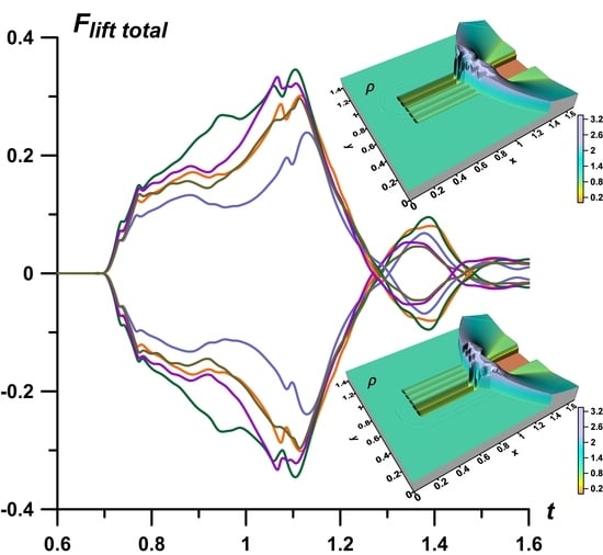
The dynamics of the total lift forces
Flifttotal for asymmetric and “reflected” asymmetric sets {
αj} are presented in
Figure 14. The dynamics of
Flifttotal are characterized by the same properties that were obtained for
Fliftwedge: the absolute value of
Flifttotal are greater for the sets {
αj} with the more heated layers, with smaller values of
αj (compare green, orange and blue curves), and it is possible to control the rate of change of
Flifttotal, by including the differently heated layers (compare green, purple and olive curves).
It can be emphasized that the dynamics of lift forces in
Figure 13 and
Figure 14 are described by the symmetrical curves. Therefore, by replacing the asymmetric set {
αj} with its “reflected” set, it is possible to obtain the oppositely directed lift forces. Thus, lift forces can be created and controlled using a thermally stratified energy source by changing the temperature values in its layers. Notably, it is assumed that the stratified energy source is located symmetrically relative to the AD body (at zero angle of attack).


