
Experimental and CFD Investigation of Directional Stability of a Box-Wing Aircraft Concept
 ,
,
Abstract
:1. Introduction
2. Materials and Methods
2.1. Wind Tunnel Experiment
2.1.1. Geometry
| Dimensions (fuselage length × wing span × fuselage height) | 0.709 × 1.1 × 0.207 m |
| Wing aspect ratio | 12 (both wings) |
| Fuselage aspect ratio | 3.42 |
| Wing sweep angle at ¼ chord | 1.6° (fore wing); 3.2° (aft wing) |
| Airfoil | NACA 3413 (fore wing); NACA 4415 (aft wing) |
| Airfoil relative thickness | 15% (both wings) |
| Wing incidence angle | 2.5° (fore wing); 2° (aft wing) |
| Elevator-to-wing area ratio | 0.17 (both wings) |
| Flaperon-to-wing area ratio | 0.03 (both wings) |
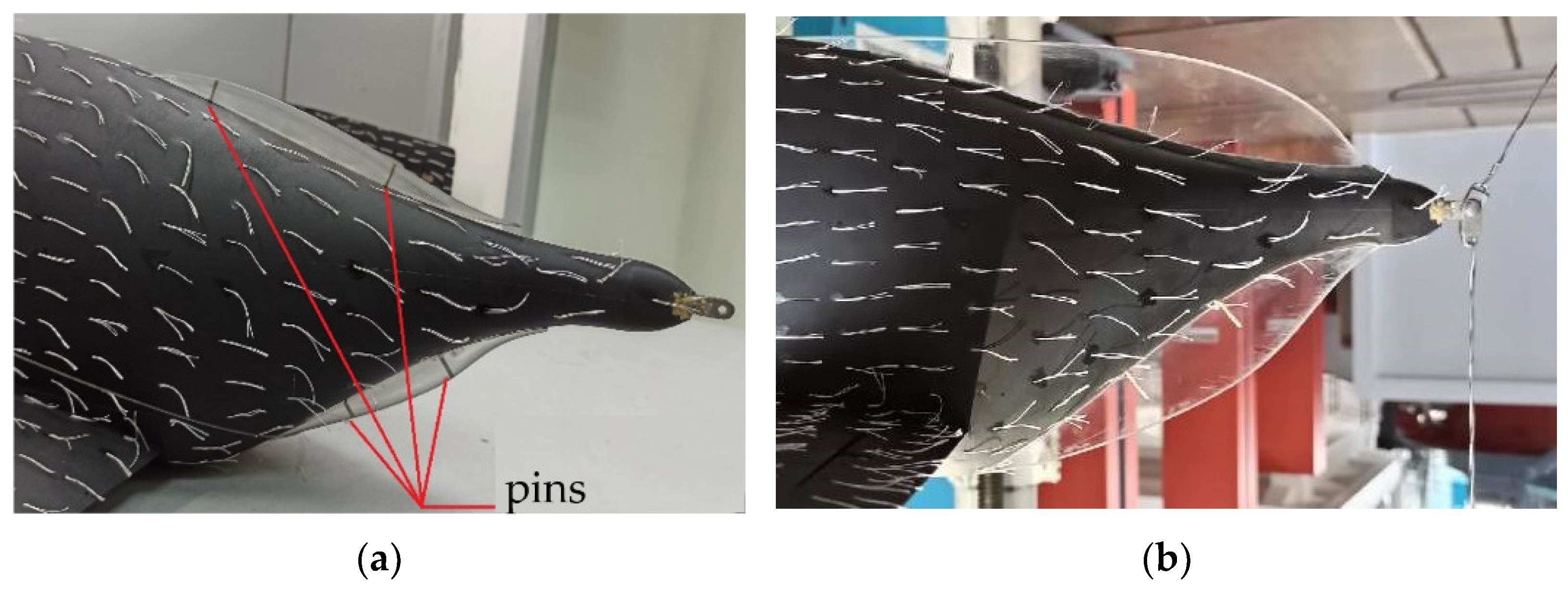
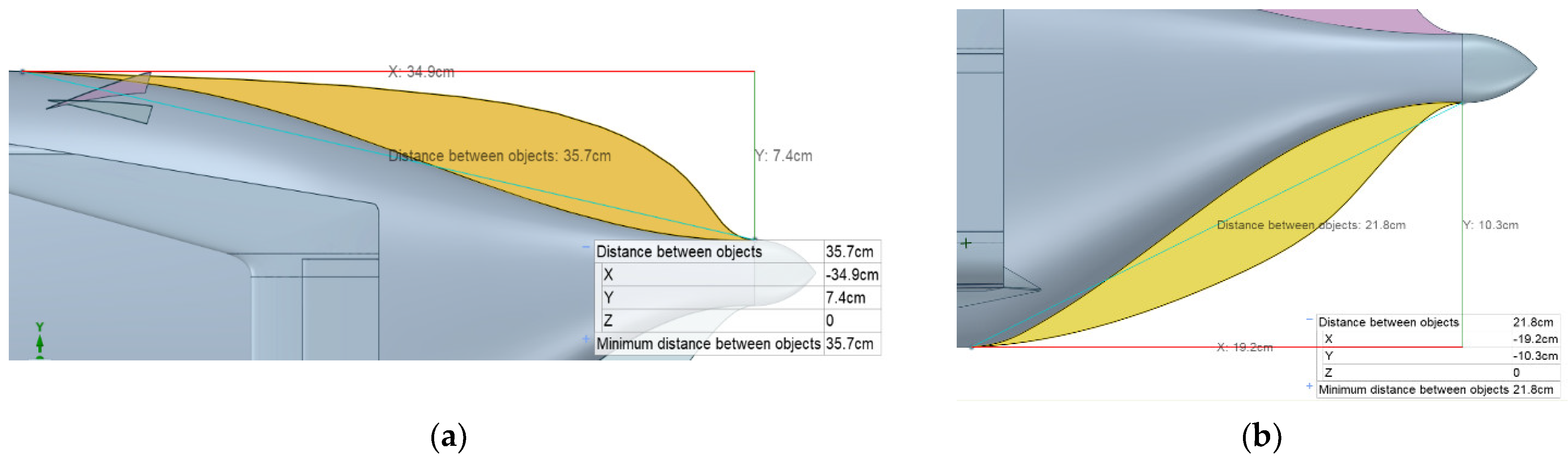
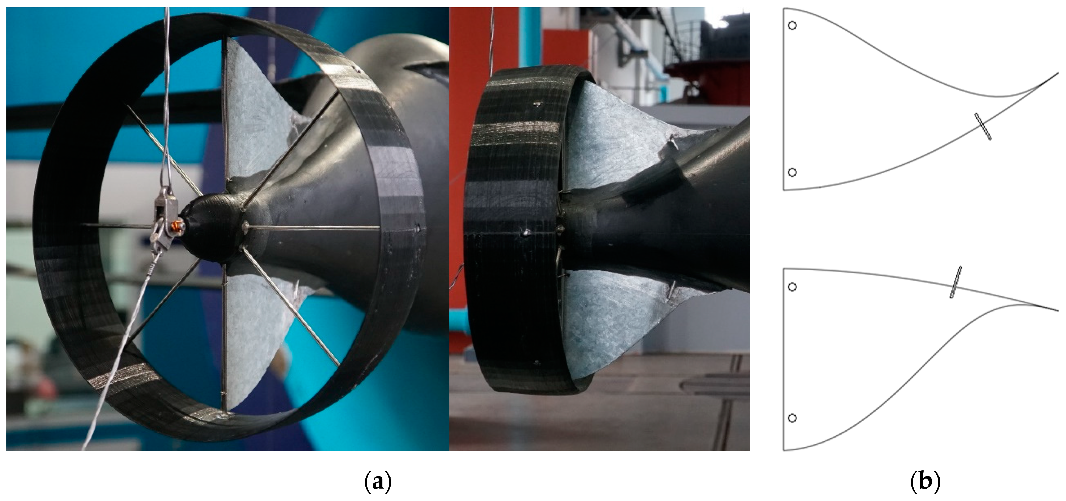
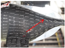
Geometry of Fishtail Surfaces
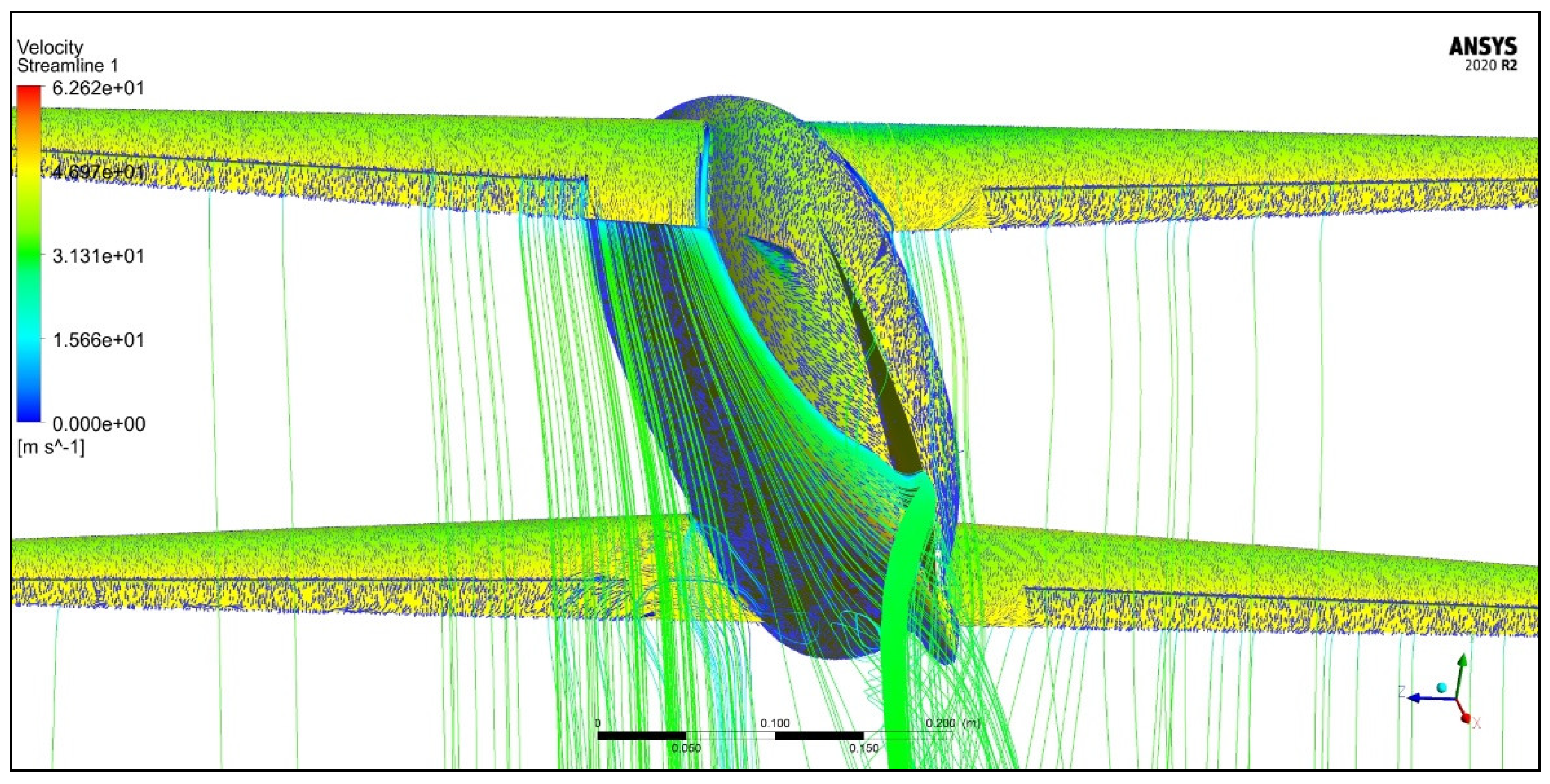
Geometry of the Duct
| Airfoil | NACA0012 (symmetric) |
| Airfoil thickness | 0.5 cm |
| Duct diameter | 17 cm |
| Hub diameter | 3 cm |
| Spokes | 7 × 0.3 cm (8 total) |
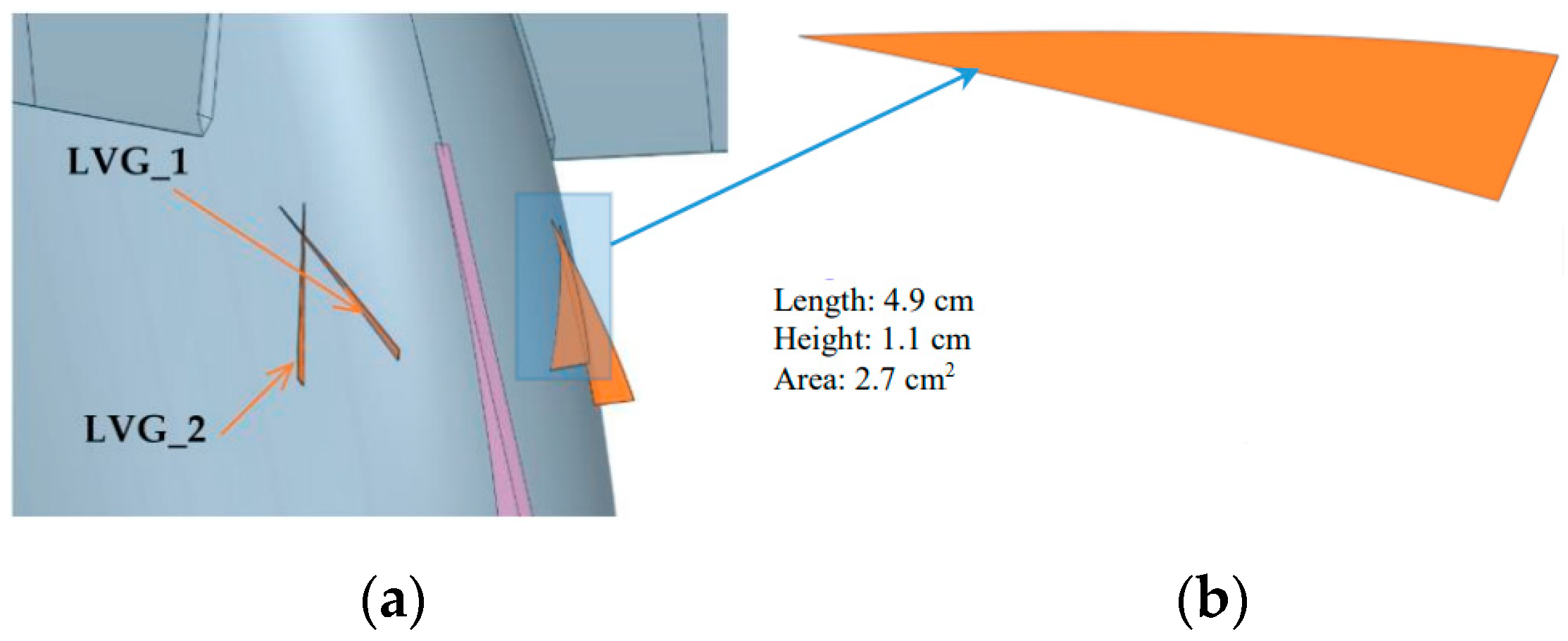
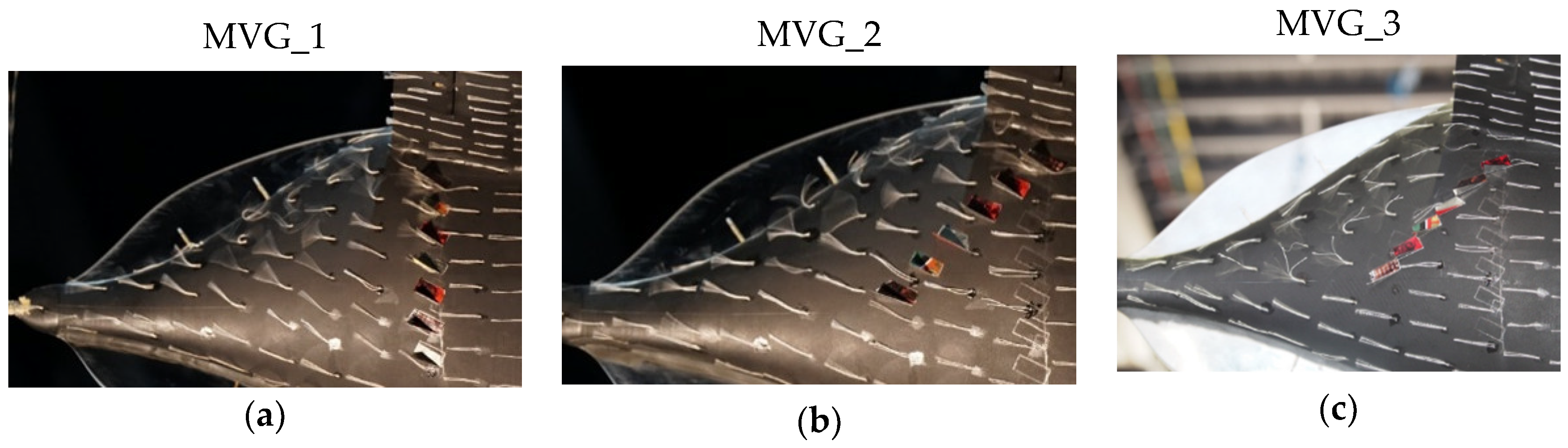
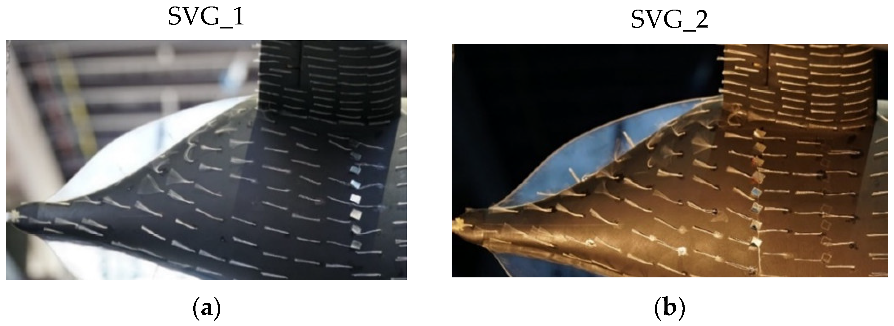
Vortex Generators
- Lateral stability improvement;
- Increasing high-lift devices efficiency.
- Bottom aft fuselage
- Outboard leading edges
- Drag reduction;
- Attached flow on high-lift devices;
- Attached flow on the fuselage aft cone.
| Skew angle δMVG | ~±35° |
| Pitch LMVG | ~1.5 cm |
| A single MVG strake height | ~0.75 cm |
| A single MVG strake length | ~1.5 cm |
| Skew angle δSVG | ~42° |
| Pitch LSVG | ~1 cm |
| A single SVG strake height | ~0.5 cm |
| A single SVG strake length | ~0.75 cm |
2.1.2. Wind Tunnel Test Conditions
| Velocity V∞ | 38 m/s |
| Pressure p∞ | 100,500 Pa |
| Temperature T∞ | 293 K |
| Turbulence intensity ε | 0.35% |
| Reynolds number Re | ~106 |
| Test section dimensions | Diameter 2.25 m * Length 3.5 m |
2.2. CFD Model
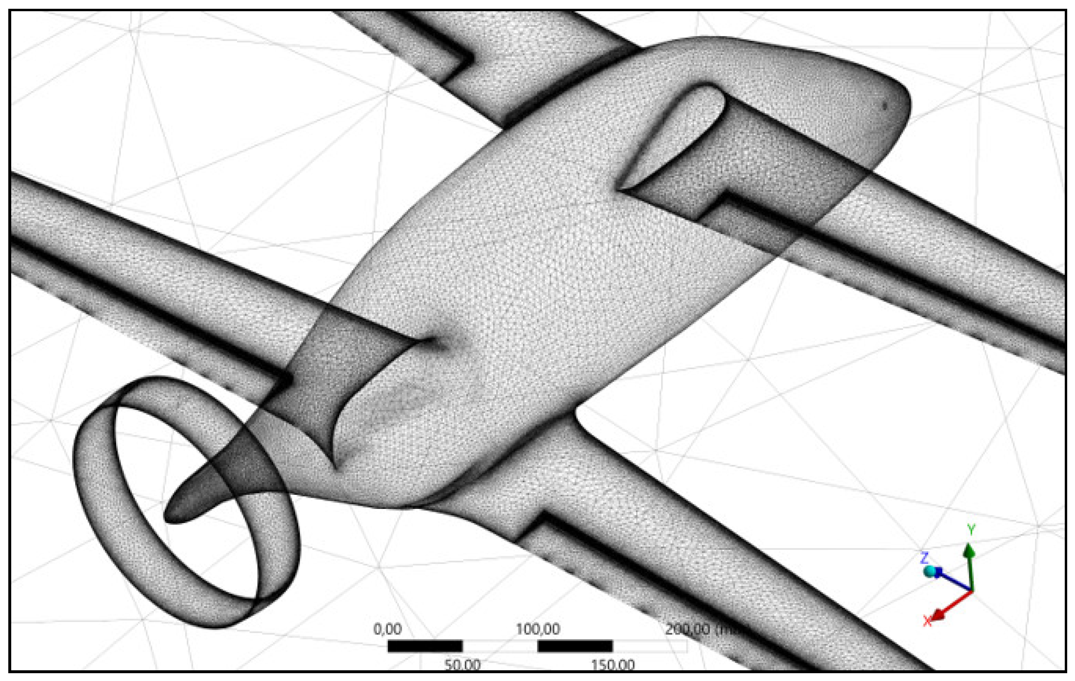
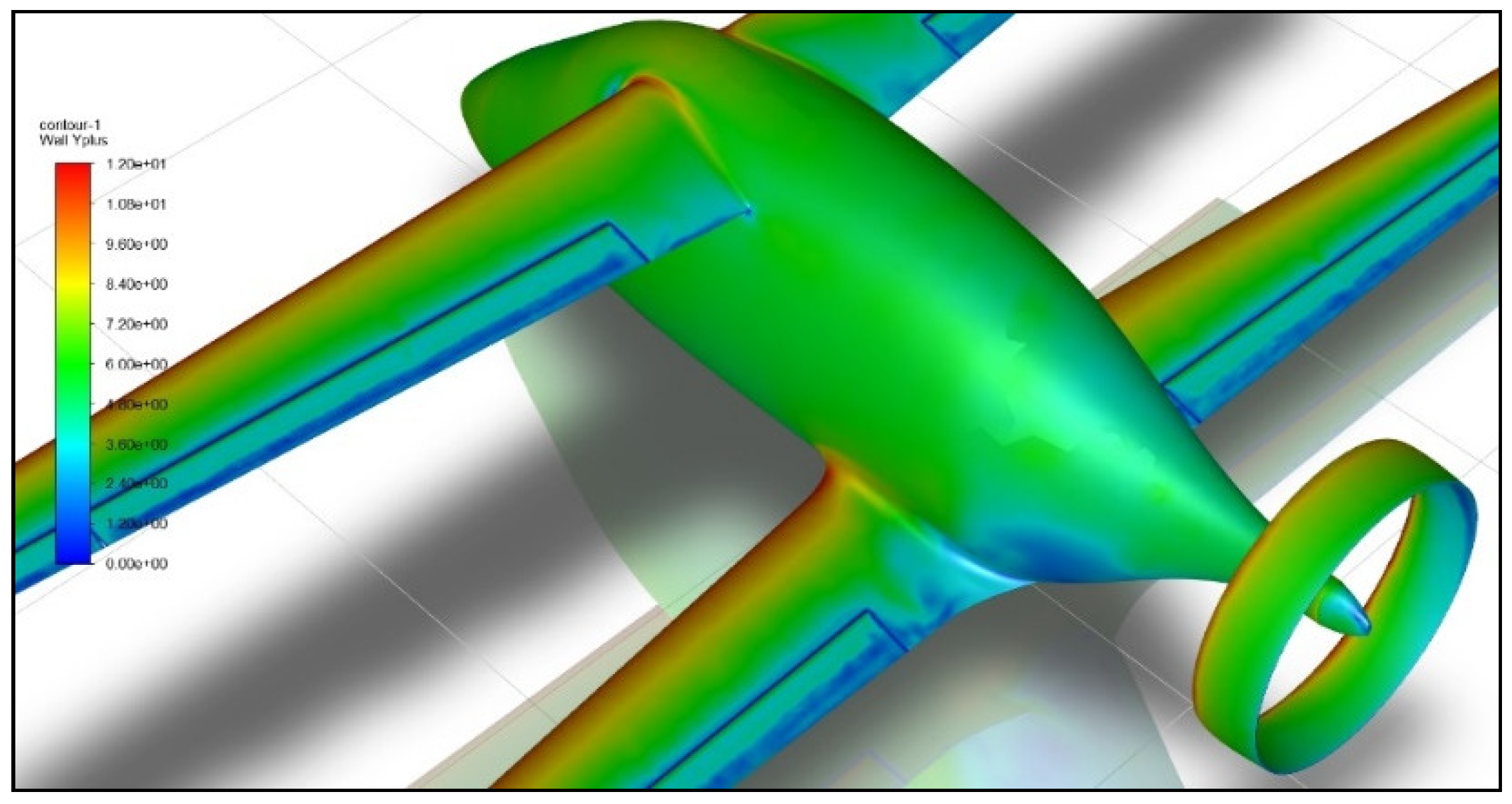
2.2.1. Meshing
2.2.2. Governing Equations, Discretization Schemes, and Turbulence Modelling
Turbulence Modelling
3. Results
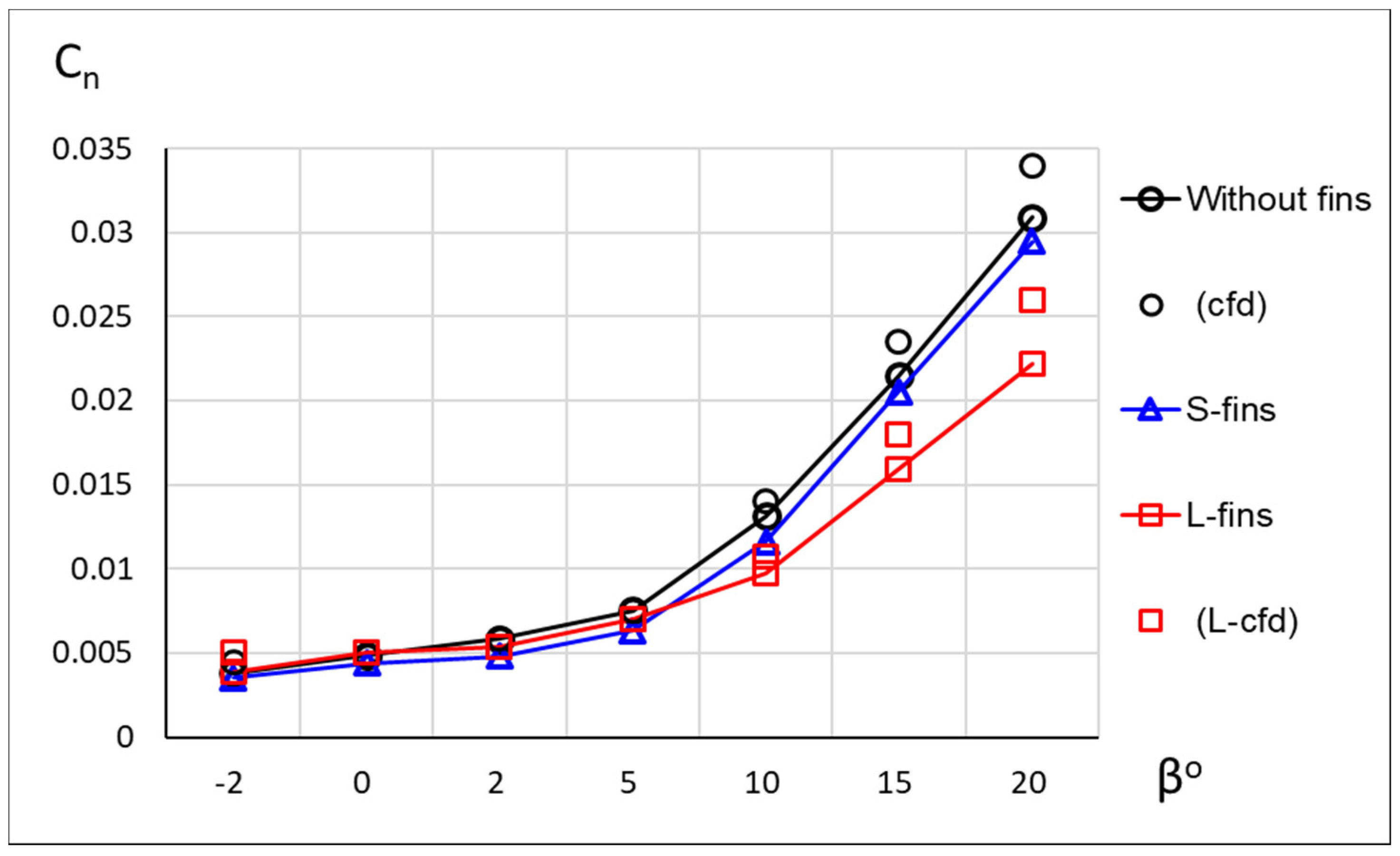
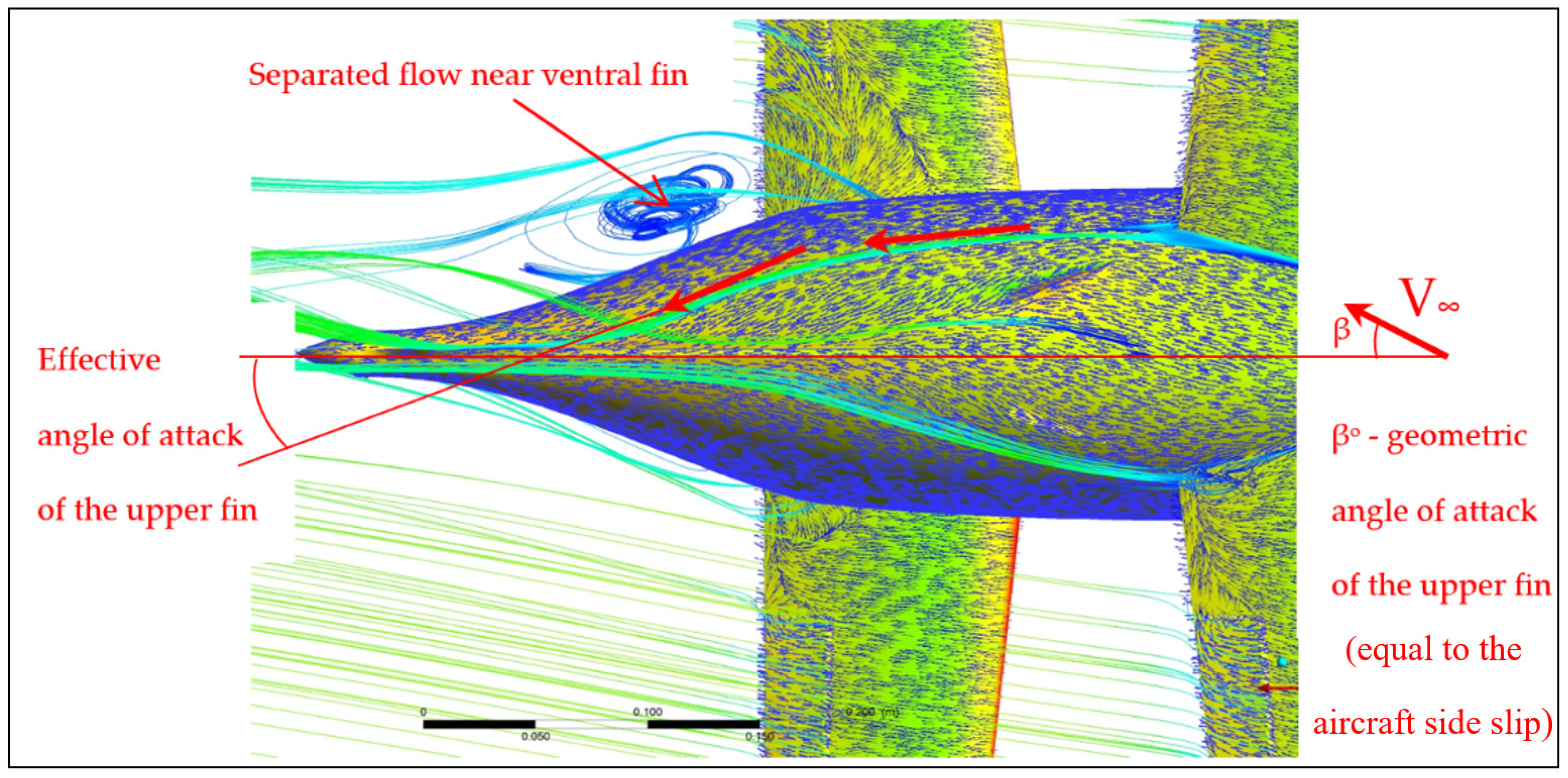
3.1. Vertical Fins
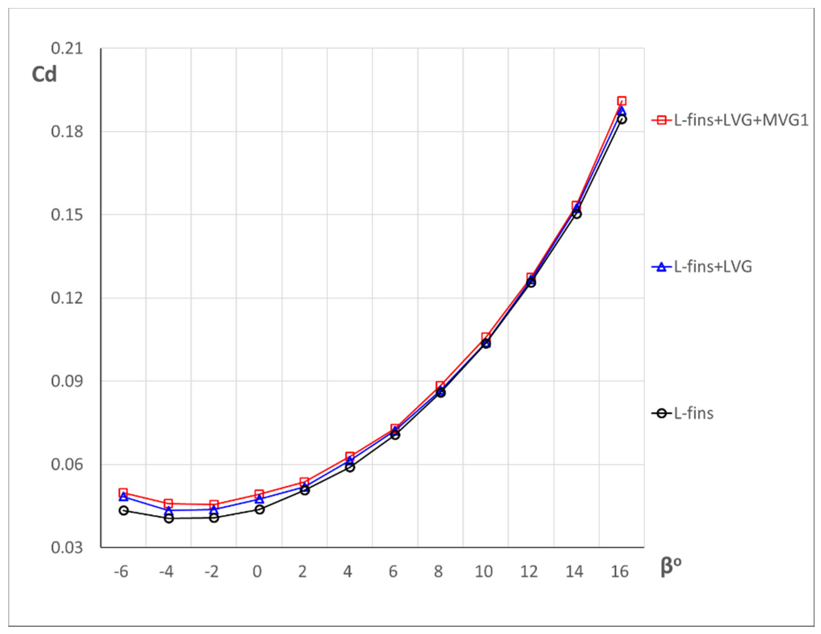
3.2. Vortex Generators
3.3. Wing Root Fairing
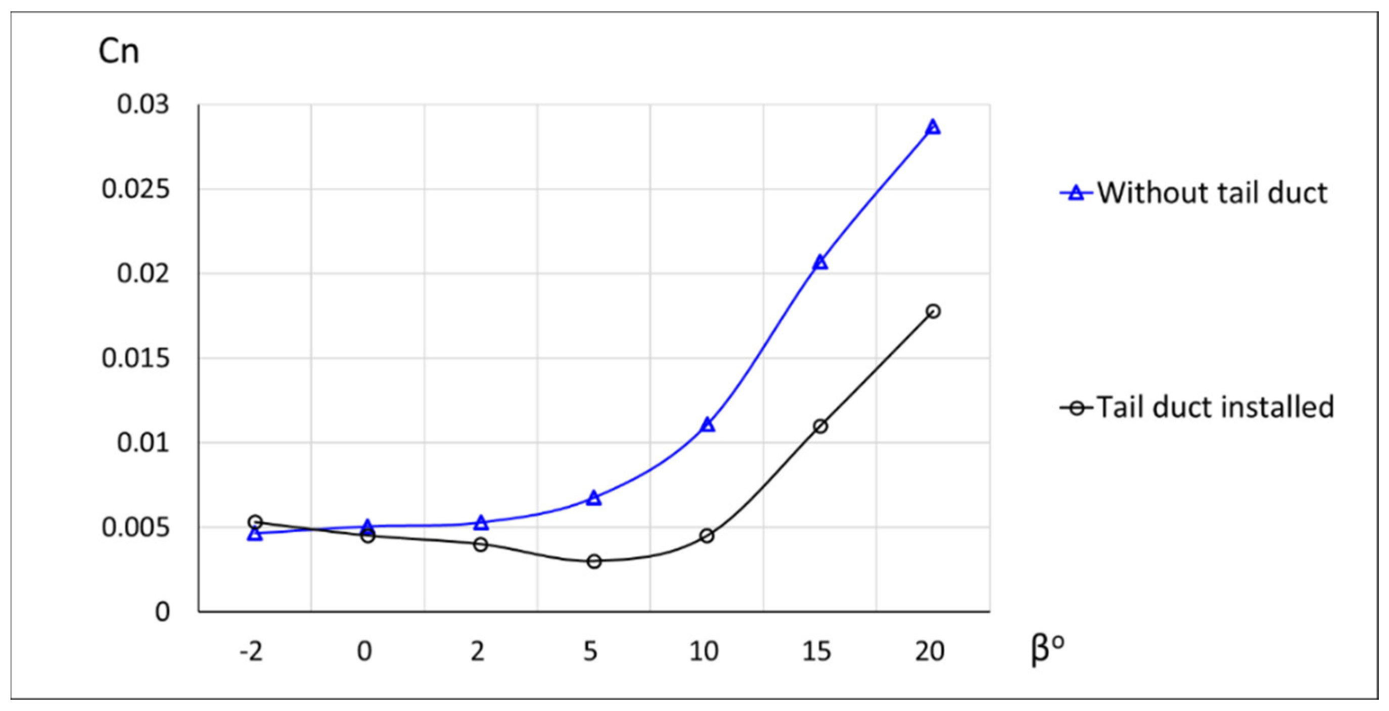
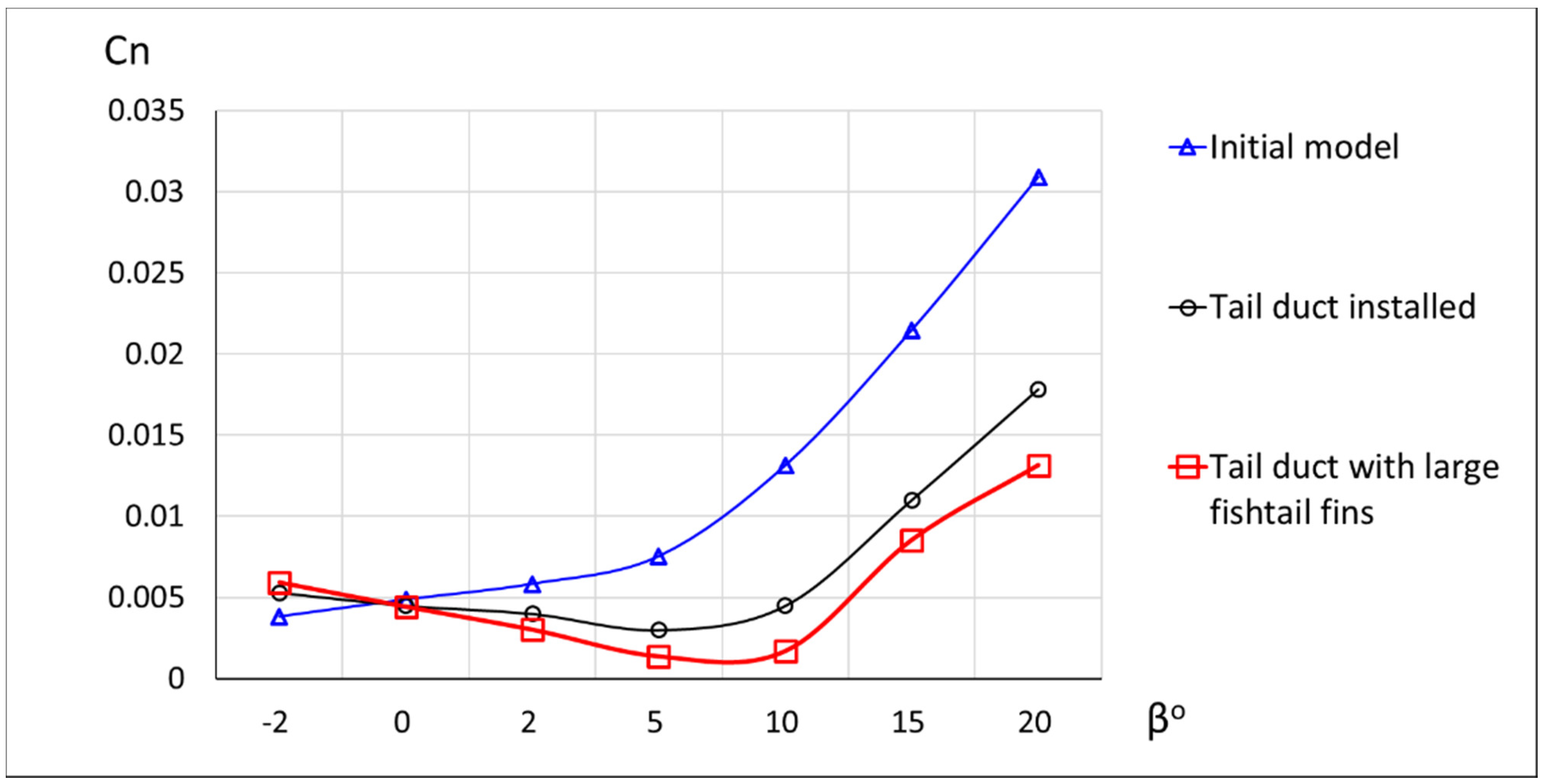
3.4. Tail Duct
3.5. Final Configuration: Tail Duct Supplied with Large Fins
4. Discussion and Conclusions
Author Contributions
Funding
Institutional Review Board Statement
Informed Consent Statement
Data Availability Statement
Conflicts of Interest
References
- Karpovich, E.A.; Liseitsev, N.K. Analytical Evaluation of Box Wing Aircraft Aerodynamic Characteristics at Early Design Stages. Russ. Aeronaut. 2019, 62, 417–422. [Google Scholar] [CrossRef]
- Karpovich, E.; Liseitsev, N. Revisiting the Longitudinal Stability and Balance of a Boxwing Aircraft. In Aerospace Engineering Bulletin; Perm National Research Polytechnic University: Perm, Russia, 2019; pp. 29–44. [Google Scholar] [CrossRef]
- Karpovich, E.A.; Kochurova, N.I.; Kuznetsov, A.V. Experimental Study of Aerodynamic Characteristics of a Boxplane Wind-Tunnel Model. Russ. Aeronaut. 2020, 63, 659–668. [Google Scholar] [CrossRef]
- Karpovich, E.; Gueraiche, D.; Sergeeva, N.; Kuznetsov, A. Investigation of a Light Boxplane Model Using Tuft Flow Visualization and CFD. Fluids 2021, 6, 451. [Google Scholar] [CrossRef]
- Karpovich, E.; Gueraiche, D.; Korotkov, D.A. A method for conceptual design of a light boxplane. Aerosp. Syst. 2022, 5, 349–356. [Google Scholar] [CrossRef]
- Frediani, A.; Cipolla, V.; Oliviero, F. Design of a prototype of light amphibious PrandtlPlane. In Proceedings of the Florida 56th AIAA/ASCE/AHS/ASC Structures, Structural Dynamics, and Materials Conference, Kissimmee, FL, USA, 5–9 January 2015. [Google Scholar] [CrossRef]
- IDINTOS: Light Amphibious PrandtlPlane. Available online: http://www.idintos.eu/eng (accessed on 26 October 2022).
- RUTAN QUICKIE. Available online: https://web.archive.org/web/20150610213002/http://www.aeroresourcesinc.com/store_/images/classifieds/179-1.pdf (accessed on 26 October 2022).
- Gagnon, H.; Zingg, D.W. Aerodynamic Optimization Trade Study of a Box-Wing Aircraft Configuration. J. Aircr. 2016, 53, 1–11. [Google Scholar] [CrossRef] [Green Version]
- Andrews, S.; Perez, R. Parametric Study of Box-Wing Aerodynamics for Minimum Drag under Stability and Maneuverability Constraints. In Proceedings of the 33rd AIAA Applied Aerodynamics Conference, Dallas, TX, USA, 22–26 June 2015. [Google Scholar] [CrossRef]
- Chau, T.; Zingg, D.W. Aerodynamic Shape Optimization of a Box-Wing Regional Aircraft Based on the Reynolds-Averaged Navier-Stokes Equations. In Proceedings of the 35th AIAA Applied Aerodynamics Conference, Denver, CO, USA, 5–9 June 2017. [Google Scholar] [CrossRef] [Green Version]
- Cipolla, V.; Frediani, A.; Abu Salem, K.; Binante, V.; Rizzo, E.; Maganzi, M. Conceptual design of Prandtl Plane transport aircraft and preliminary CFD investigation of transonic flight. In Proceedings of the American Institute of Aeronautics and Astronautics 2018 Aviation Technology, Integration, and Operations Conference, Atlanta, Georgia Aviation Technology, Integration, and Operations Conference, Atlanta, GA, USA, 25–29 June 2018. [Google Scholar] [CrossRef]
- Andrews, S.A.; Perez, R.E. Analytic Study of the Conditions Required for Longitudinal Stability of Dual-Wing Aircraft. Proc. Inst. Mech. Eng. J. Aerosp. Eng. 2017, 232, 958–972. [Google Scholar] [CrossRef]
- Stephen, A.A.; Ruben, E.P. Stability and Control Effects on the Design Optimization of a Box-Wing Aircraft. In Proceedings of the 14th AIAA Aviation Technology, Integration, and Operations Conference, Atlanta, GA, USA, 16–20 June 2014. [Google Scholar] [CrossRef]
- Stephen, A.A.; Ruben, E.P. Multidisciplinary Analysis of a Box-Wing Aircraft Designed for a Regional-Jet Mission. In Proceedings of the 16th AIAA/ISSMO Multidisciplinary Analysis and Optimization Conference, Dallas, TX, USA, 22–26 June 2015. [Google Scholar] [CrossRef]
- Cipolla, V.; Abu Salem, K.; Picchi, S.M.; Vincenzo, B. Preliminary design and performance analysis of a box-wing transport aircraft. In Proceedings of the AIAA Scitech 2020 Forum, Orlando, FL, USA, 6–10 January 2020. [Google Scholar] [CrossRef]
- Abu Salem, K.; Binante, V.; Cipolla, V.; Maganzi, M. PARSIFAL Project: A Breakthrough Innovation in Air Transport. Aerotec. Missili Spaz. 2018, 97, 40–46. [Google Scholar] [CrossRef] [Green Version]
- PARSIFAL Project. Available online: https://parsifalproject.eu/ (accessed on 26 October 2022).
- Godard, G.; Stanislas, M. Control of a decelerating boundary layer. Part 1: Optimization of passive vortex generators. Aerosp. Sci. Technol. 2006, 10, 181–191. [Google Scholar] [CrossRef]


| Configuration | Skew Angle δ° | Height h cm | Length l cm | VGs Pitch in a Pattern L cm | Patterns Pitch λ | Min. Distance to Separation Line ∆Xvg cm |
|---|---|---|---|---|---|---|
| LVG_1 | 42 | 1.1 | 4.9 | 4.5 | - | - |
| LVG_2 | −42 | 1.1 | 4.9 | 4.5 | - | - |
| MVG_1 | 35 | 0.75 | 1.5 | 1.5 | - | 2 |
| MVG_2 | 35 | 0.75 | 1.5 | 1.5 | - | 0 |
| MVG_3 | −35 | 0.75 | 1.5 | 1.5 | - | 0 |
| SVG_1 | 42 | 0.5 | 0.75 | 1 | - | 6 |
| SVG_2 | 42 | 0.5 | 0.75 | 1 | - | 2 |
| Illustration of the geometrical parameters of the vortex generator [19] |  | |||||
| β° | 4° | 7° | 9° |
|---|---|---|---|
| Tuft flow visualization |  |  |  |
| Flow field of the inner (shaded) side of the fuselage |  | 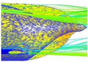 |  |
| Upper fin | Effective α~β° | Effective α < β° | Effective α < 0 < β° |
| Ventral fin | Weak separation | partially separated | Full separation |
| β° | 3° | 7° | 15° |
|---|---|---|---|
| Cp scale |  | ||
| Top View LVG_1 | Outer strake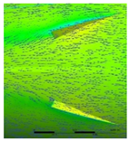 Inner strake |  |  |
| Inner strake | Moderate—small α | Small α | α ~ 0 |
| Outer strake | Moderate α | High α | Post-stall α |
| Outer strake suction side |  |  |  |
| Outer strake remark | Small angle of attack—low vortex intensity | Low pressure covering the entire surface—highest intensity of the vortex. | Low pressure only near the leading edge indicating a stall—overall less vortex intensity |
| Configuration | L-Fins + LVG | L-Fins + LVG + SVG_1 | L-Fins + LVG + SVG_2 |
|---|---|---|---|
| Tuft visualization at α = 2° | 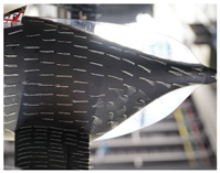 | 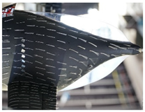 | 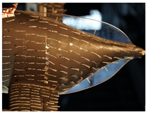 |
| Remarks | Both SVG configurations did not lead to significant reduction of the aft cone separated area. Placing the VG pattern closer downstream led to a slight shift of separation below. | ||
| Configuration | L-Fins + LVG | L-Fins + LVG + MVG_1 | L-Fins + LVG + MVG_2 |
|---|---|---|---|
| Tuft visualization at α= 2° |  | 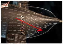 | 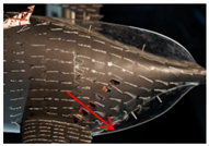 |
| Remarks |
| L-fins + LVG + MVG_3 | |
 | |||
| Configuration | Without Wing Root Fairing | Wing Root Fairing Installed |
|---|---|---|
| Tuft flow Visualization at α = 8° |  | 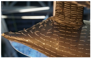 |
| β° | 3° | 7° | 15° |
|---|---|---|---|
| Cp scale |  | ||
| Pressure coefficient visualization in a horizontal mid-section plane | 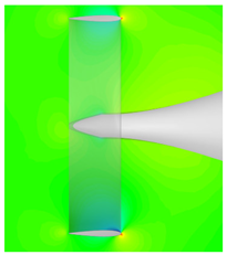 |  | 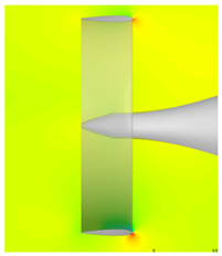 |
| Inner (shaded) section | 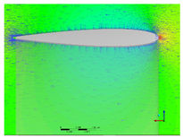 |  |  |
| Flow | Attached | Attached | Attached |
| Local effective α | α ~ 0 (symmetric pressure field) | α ~ 0 (symmetric pressure field) | moderate α |
| Outer section |  | 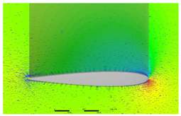 | 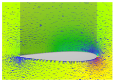 |
| Flow | Attached | Partially separated | Fully separated |
| Local effective α | Moderate α ~ β ~ 3° | High α ~ β ~ 7° | Extremely high local effective angle of attack α ~ β ~ 15° |
| Conclusion | The outer section, which was outside the fuselage influence, had an effective α equal to the aircraft (undisturbed) sideslip angle β. The inner section, which was shaded by the fuselage sidewash, experienced a significant loss of effective α, which consequently did not increase with increasing β and hence did not contribute to generating a yaw moment. | ||
Publisher’s Note: MDPI stays neutral with regard to jurisdictional claims in published maps and institutional affiliations. |
© 2022 by the authors. Licensee MDPI, Basel, Switzerland. This article is an open access article distributed under the terms and conditions of the Creative Commons Attribution (CC BY) license (https://creativecommons.org/licenses/by/4.0/).
Share and Cite
Djahid, G.; Elena, K.; Maxim, P.; Alexander, K.; Popov, S.; Sinha, M. Experimental and CFD Investigation of Directional Stability of a Box-Wing Aircraft Concept. Fluids 2022, 7, 340. https://doi.org/10.3390/fluids7110340
Djahid G, Elena K, Maxim P, Alexander K, Popov S, Sinha M. Experimental and CFD Investigation of Directional Stability of a Box-Wing Aircraft Concept. Fluids. 2022; 7(11):340. https://doi.org/10.3390/fluids7110340
Chicago/Turabian StyleDjahid, Gueraiche, Karpovich Elena, Pikulev Maxim, Kuznetsov Alexander, Sergey Popov, and Manoranjan Sinha. 2022. "Experimental and CFD Investigation of Directional Stability of a Box-Wing Aircraft Concept" Fluids 7, no. 11: 340. https://doi.org/10.3390/fluids7110340