

Gas–Liquid Mass Transfer Intensification for Selective Alkyne Semi-Hydrogenation with an Advanced Elastic Catalytic Foam-Bed Reactor

Abstract
:1. Introduction
2. Materials and Methods
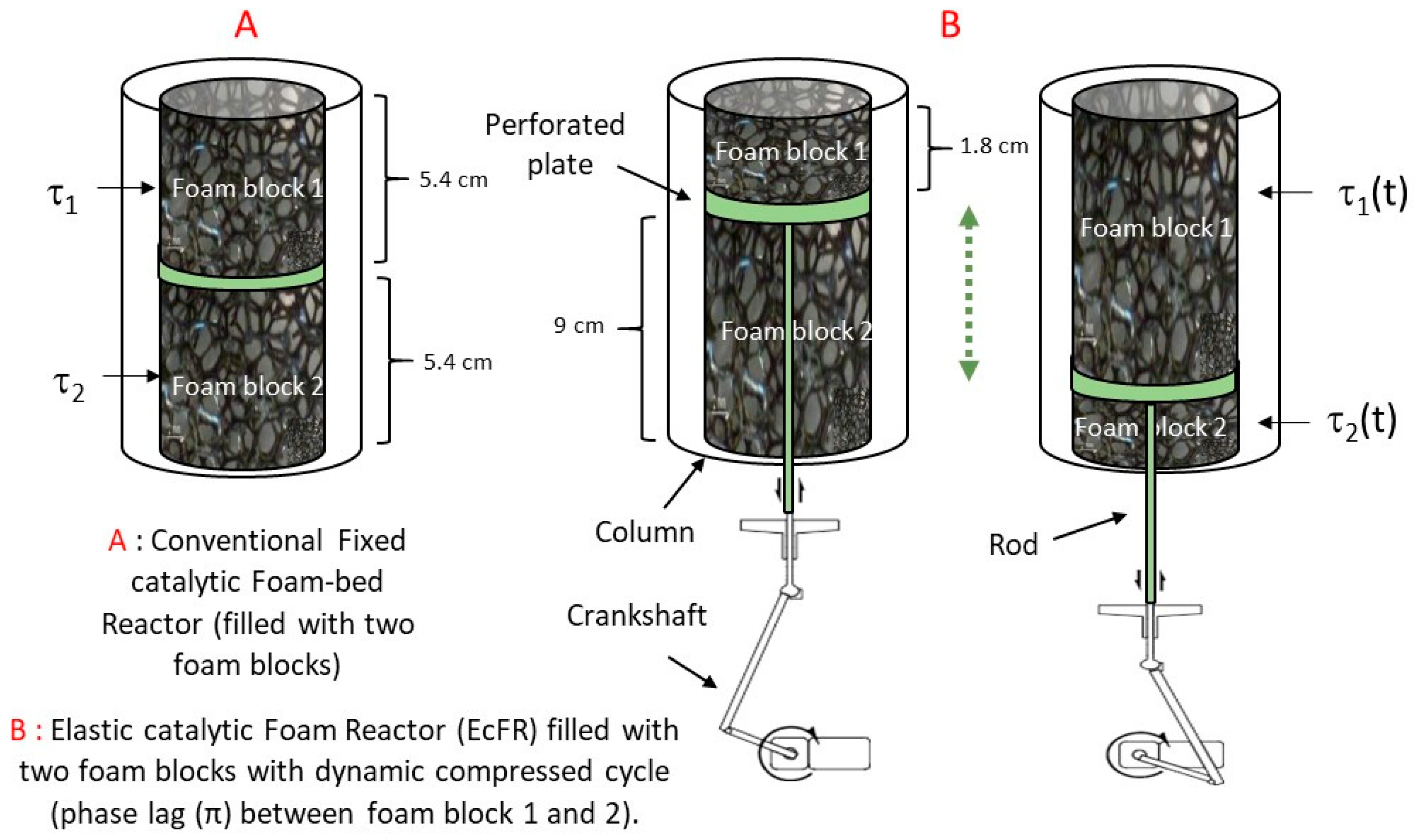
2.1. Elastic Foam Support
2.2. Preparation of Catalytic Elastic Foam
- Coating of the polyurethane foam (PUF) with polydopamine (PDA)
- Functionalization of PDA@PUF with [PdCl2(NH3)4]·H2O
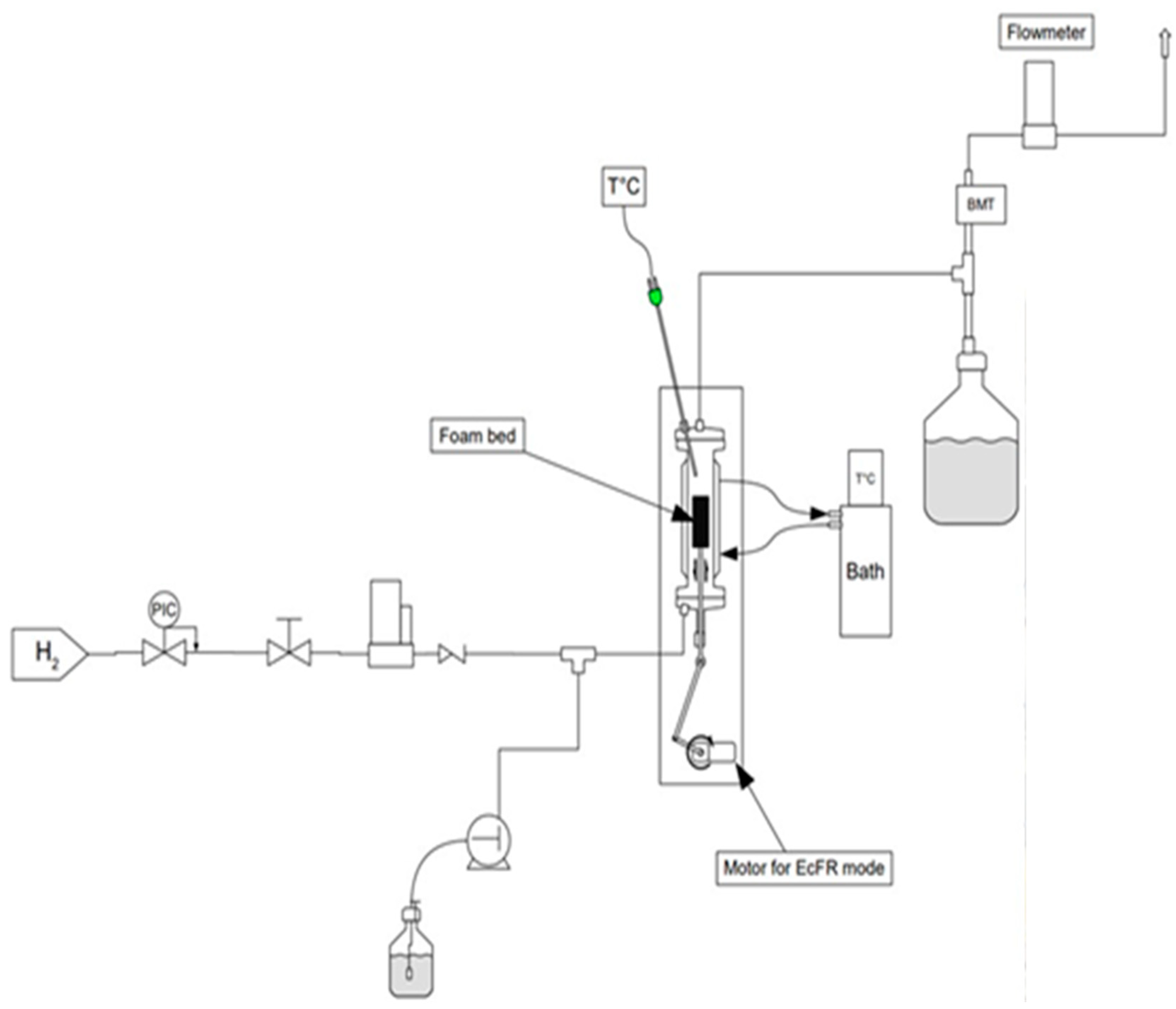
2.3. Reactor, Apparatus, and Phenylacetylene Semi-Hydrogenation Procedure
3. Results
4. Discussion
5. Conclusions
Author Contributions
Funding
Data Availability Statement
Acknowledgments
Conflicts of Interest
Nomenclature
| a | Window (or pore) diameter, µm |
| aGL | Interfacial gas–liquid area per unit volume of liquid, m2L m−3L |
| ap | Packing surface area per unit volume, m2·m−3 |
| ac | Specific surface area (m2·m−3) |
| C | Concentration mol·m−3 |
| Dax | Axial dispersion coefficient in the liquid phase, m2·s−1 |
| DR | Reactor diameter, mm |
| ds | Struts diameter, m |
| He | Henry coefficient, m3L Pa mol−1 |
| ID | Internal diameter of the cylindric foam blocs, mm |
| k1 | Kinetic constant, (m6/kmol·kg·s) |
| KB | Kinetic constant, m3/kmol |
| K | Rate constant, s−1 |
| kla | Overall gas–liquid mass transfer coefficient, s−1 |
| L0 | length of an initial block foam, m |
| L | Reactor length, m |
| QL | Liquid flowrate, mL/min |
| QG | Gas flowrate, NmL/min |
| R | Universal gas constant, 8314 Pa·m3 K−1 mol−1 |
| ReL | Modified Reynolds number for the liquid phase, dimensionless |
| ReOL | Modified Oscillation Reynolds for the liquid phase, dimensionless |
| r | Hydrogenation rate of phenylacetylene kmol·L−1·s−1 |
| S | Selectivity |
| Sc | Schmidt number, dimensionless |
| Sh | Sherwood number, dimensionless |
| t | Time, s |
| tc | Residence time, s−1 |
| T | Temperature, K |
| ug | Superficial gas phase velocity, m·s−1 |
| ul (or Ul) | Superficial liquid phase velocity, m·s−1 |
| V | Reactor volume, m3 |
| w | Mass of catalyst (Pd) by reactor volume, kg/m3 |
| Χ | Conversion, dimensionless |
| Greek symbols: | |
| E | Foam porosity, dimensionless |
| εl | Liquid holdup, dimensionless |
| εg | Gas holdup, dimensionless |
| ϕ | Cell diameter, µm |
| τ1,2,(t) | Compression ratio, dimensionless |
| Abbreviations: | |
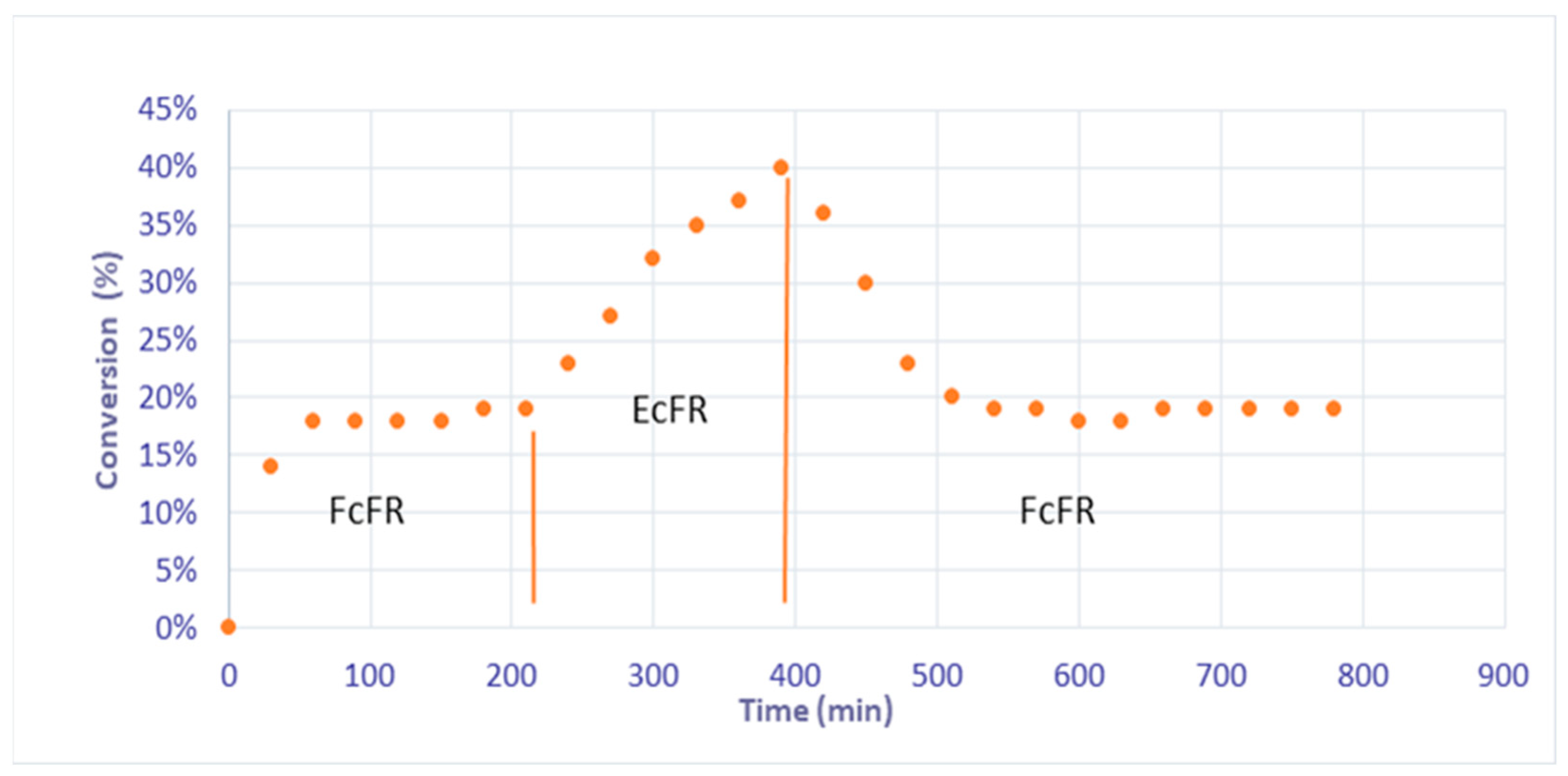
| EcFR | Elastic Catalytic Foam-bed Reactor |
| EFR | Elastic Foam-bed Reactor |
| FcFR | Fixed Catalytic Foam-bed Reactor |
| GC | Gas chromatography |
| ICP-AES | Inductively coupled plasma atomic emission spectroscopy |
| PDA | Polydopamine |
| PUF | Polyurethane foam |
References
- Langley, N.; Harrison, S.; Van Hille, R. A critical evaluation of CO2 supplementation to algal systems by direct injection. Biochem. Eng. J. 2012, 68, 70–75. [Google Scholar] [CrossRef]
- Utikar, R.P.; Ranade, V. Intensifying multiphase reactions and reactors strategies and examples. ACS Sustain. Chem. Eng. 2017, 5, 3607–3622. [Google Scholar] [CrossRef]
- Mills, P.L.; Duduković, M.P. Analysis of catalyst effectiveness in trickle-bed reactors processing volatile or nonvolatile reactants. Chem. Eng. Sci. 1980, 35, 2267–2279. [Google Scholar] [CrossRef]
- Baharudin, L.; Inder, A.; Watson, M.; Yip, A. Process intensification in multifunctional reactors: A review of multi-functionlity by catalytic structures, internals, operating modes, and unit integrations. Chem. Eng. Process. 2021, 168, 108561. [Google Scholar] [CrossRef]
- Nigam, K.D.P.; Larachi, F. Process intensification in trickle-bed reactors. Chem. Eng. Sci. 2005, 60, 5880–5894. [Google Scholar] [CrossRef]
- Lacroix, M.; Nguyen, P.; Schweich, D.; Pham-Huu, C.; Poncet, S.S.; Edouard, D. Pressure drop measurements and modeling on SiC foams. Chem. Eng. Sci. 2007, 62, 3259–3267. [Google Scholar] [CrossRef]
- Edouard, D.; Lacroix, M.; Pham, C.; Mbodji, M.; Pham-Huu, C. Experimental measurements and multiphase flow models in solid SiC foam beds. AIChE 2008, 54, 2823–2832. [Google Scholar] [CrossRef]
- Stemmet, C.P.; Jongmans, J.N.; van der Schaaf, J.; Kuster, B.F.M.; Schouten, J.C. Hydrodynamics of gas–liquid counter-current flow in solid foam packings. Chem. Eng. Sci. 2005, 60, 6422–6429. [Google Scholar] [CrossRef]
- Stemmet, C.P.; Van der Schaaf, J.; Kuster, B.F.M.; Schouten, J.C. Solid foam packings for multiphase reactors. Modelling of liquid holdup and mass transfer. Chem. Eng. Res. Des. 2006, 84, 1134–1141. [Google Scholar] [CrossRef]
- Stemmet, C.P.; Meeuwse, M.; van der Schaaf, J.; Kuster, B.F.M.; Schouten, J.C. Gas–liquid mass transfer and axial dispersion in solid foam packings. Chem. Eng. Sci. 2007, 62, 5444–5450. [Google Scholar] [CrossRef]
- Saber, M.; Huu, T.T.; Pham-Huu, C.; Edouard, D. Residence time distribution, axial liquid dispersion and dynamic–static liquid mass transfer in trickle flow reactor containing β-SiC open-cell foams. Chem. Eng. J. 2012, 185–186, 294–299. [Google Scholar] [CrossRef]
- Zapico, R.R.; Marín, P.; Díez, F.V.; Ordóñez, S. Liquid hold-up and gas–liquid mass transfer in an alumina open-cell foam. Chem. Eng. Sci. 2016, 143, 297–304. [Google Scholar] [CrossRef]
- Nguyen, T.; Swesi, Y.; Edouard, D.; Fongarland, P. Platelet Millireactor Filled with Open Cell Foam-Supported Pt Nanoparticles for a Three-Phase Catalytic System. Ind. Eng. Chem. Res. 2019, 58, 9352–9361. [Google Scholar] [CrossRef]
- Cai, X.; Wörner, M.; Marschall, H.; Deutschmann, O. Numerical study on the wettability depend interaction of a rising bubble with a periodic open cell cellular structure. Catal. Today. 2016, 273, 151–160. [Google Scholar] [CrossRef]
- Lämmermann, M.; Horak, G.; Schwieger, W.; Freund, H. Periodic open cellular structures (POCS) for intensification of multiphase ractors: Liquid holdup and two-phase presure drop. Chem. Eng. Process. 2018, 126, 178–189. [Google Scholar] [CrossRef]
- Lange, R.; Hanika, J.; Stradiotto, D.; Hudgins, R.R.; Silveston, P.L. Investigations of periodically operated trickle-bed reactors. Chem. Eng. Sci. 1994, 49, 5615–5621. [Google Scholar] [CrossRef]
- Castellari, A.T.; Haure, P.M. Experimental study of the periodic operation of a trickle-bed reactor. AIChE 1995, 41, 1593–1597. [Google Scholar] [CrossRef]
- Banchero, M.; Manna, L.; Sicardi, S.; Ferri, A. Experimental investigation of fast mode liquid modulation in a trickle-bed reactor. Chem. Eng. Sci. 2004, 59, 4149–4154. [Google Scholar] [CrossRef]
- Boelhouwer, J.G.; Piepers, H.W.; Drinkenburg, B.A.H. Advantages of forced non-steady operated trickle-Bed reactors. Chem. Eng. Technol. 2002, 25, 647–650. [Google Scholar] [CrossRef]
- Dietrich, W.; Grünewald, M.; Agar, D.W. Dynamic modelling of periodically wetted catalyst particles. Chem. Eng. Sci. 2005, 60, 6254–6261. [Google Scholar] [CrossRef]
- Härting, H.U.; Lange, R.; Larachi, F.; Schubert, M. A novel inclined rotating tubular fixed bed reactor concept for enhancement of reaction rates and adjustment of flow regimes. Chem. Eng. J. 2015, 281, 931–944. [Google Scholar] [CrossRef]
- Dashliborun, A.M.; Larachi, F.; Taghavi, S.M. Gas-liquid mass-transfer behavior of packed-bed scrubbers for floating/offshore CO2 capture. Chem. Eng. J. 2019, 377, 119236. [Google Scholar] [CrossRef]
- Ferroni, C.; Bracconi, M.; Ambrosetti, M.; Groppi, G.; Maestri, M.; Freund, H.; Tronconi, E. Process intensification in mass-transfer limited catalytic reactors through anisotropic periodic open cellular structures. Chem. Eng. Process. 2024, 195, 109613. [Google Scholar] [CrossRef]
- Duduković, M.P.; Larachi, F.; Mills, P.L. Multiphase catalytic reactors: A perspective on current knowledge and future trends. Catal. Rev. 2002, 44, 123–246. [Google Scholar] [CrossRef]
- Michaud, M.; Bornette, F.; Rautu, E.; More, S.H.; Martinez Mendez, M.L.; Jierry, L.; Edouard, D. Unprecented continuous elastic foam-bed reactor for CO2 capture. Chem. Eng. J. 2023, 452, 138604. [Google Scholar] [CrossRef]
- Lefebvre, L.; Kelber, J.; Jierry, L.; Ritleng, V.; Edouard, D. Polydopamine-coated open cell polyurethane foam as an efficient and easy-to-regenerate soft structured catalytic support (S2CS) for the reduction of dye. J. Environ. Chem. Eng. 2017, 5, 79–85. [Google Scholar] [CrossRef]
- Pardieu, E.; Chau, N.T.T.; Dintzer, T.; Romero, T.; Favier, D.; Roland, T.; Edouard, D.; Jierry, L.; Ritleng, V. Polydopamine-coated open cell polyurethane foams as an inexpensive, flexible yet robust catalyst support: A proof of concept. Chem. Commun. 2016, 52, 4691–4693. [Google Scholar] [CrossRef] [PubMed]
- Ait Khouya, A.; Mendez Martinez, M.L.; Bertani, P.; Romero, T.; Favier, D.; Roland, T.; Guidal, V.; Bellière-Baca, V.; Edouard, D.; Jierry, L.; et al. Coating of polydopamine on polyurethane open cell foams to design soft structured supports for molecular catalysts. Chem. Commun. 2019, 55, 11960–11963. [Google Scholar] [CrossRef]
- Simfoam. Available online: https://simfoam.alsace.cnrs.fr/Web/Home.aspx (accessed on 10 April 2024).
- Peng, H.; Zhang, X.; Papaefthimiou, V.; Pham-Huu, C.; Ritleng, V. Pd-functionalized polydopamine-coated polyurethane foam: A readily prepared and highly reusable structured catalyst for selective alkyne semi-hydrogenation and Suzuki coupling under air. Green Chem. 2023, 25, 264–279. [Google Scholar] [CrossRef]
- Chaudhari, R.V.; Jaganathan, R.; Kolhe, D.S.; Emig, G.; Hofmann, H. Kinetic modelling of a complex consecutive reaction in a slurry reactor: Hydrogenation of phenylacetylene. Chem. Eng. Sci. 1986, 41, 3073–3081. [Google Scholar] [CrossRef]
- Ramachandran, P.A.; Chaudhari, R.V. Three-Phase Catalytic Reactors; Gordon and Breach; Science Publishers: New York, NY, USA, 1983. [Google Scholar]
- Lévêque, J.; Philippe, R.; Zanota, M.; Meille, V.; Sarrazin, F.; Baussaron, L.; De Bellefon, C. Hydrodynamics and mass transfer in a tubular reactor containing foam packings for intensification of G-L-S catalytic reactions in co-current up-flow configuration. Chem. Eng. Res. Design 2016, 109, 686–697. [Google Scholar] [CrossRef]
- Bouras, H.; Haroun, Y.; Philippe, R.; Augier, F.; Fongarland, P. CFD modeling of mass transfer in gas-liquid-solid catalytic reactors. Chem. Eng. Sci. 2021, 233, 116378. [Google Scholar] [CrossRef]


| Characteristic | Value |
|---|---|
| Strut size (ds) | 220 µm |
| Window size (a) | 780 µm |
| Cell size (ϕ) | 2500 µm |
| Density | 0.027–0.033 |
| Total porosity (ε) | 0.97 |
| Gas holdup (εg) | 0.02 [13] |
| Liquid holdup (εl) | 0.95 [13] |
| Specific surface area (ac) * | 1340 m−1 |
| Pressure drop * | 15 Pa/m |
| Tortuosity * | 1.24 |
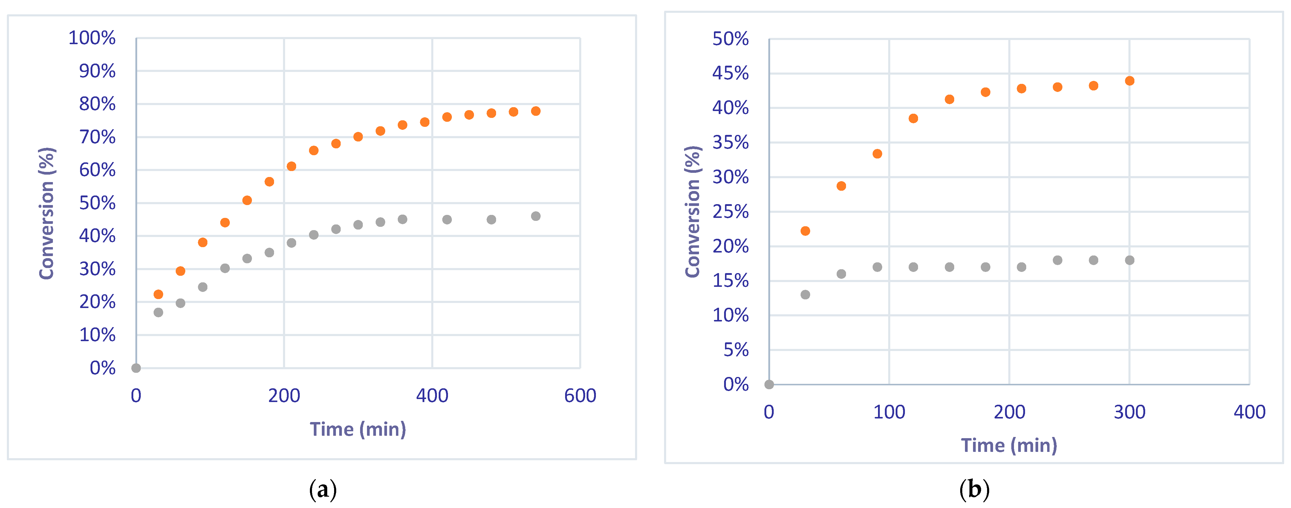
| Liquid Flow | Theoretical Conversion (Equation (4)) | Experimental Conversion—FcFR | Experimental Conversion—EcFR |
|---|---|---|---|
| 2 mL/min | 85.8% | 44% | 78% |
| 5 mL/min | 39.8% | 19% | 45% |
| FcFR/FFR | EcFR/EFR | |||
|---|---|---|---|---|
| QL (mL/min) | This Work | With Correlation | This Work | With Correlation |
| 2 | 8.1 × 10⁻⁴ | 9.1 × 10⁻⁴ | - | 9.7 × 10⁻³ |
| 5 | 9.8 × 10⁻⁴ | 2.3 × 10⁻³ | - | 1.5 × 10⁻² |
Disclaimer/Publisher’s Note: The statements, opinions and data contained in all publications are solely those of the individual author(s) and contributor(s) and not of MDPI and/or the editor(s). MDPI and/or the editor(s) disclaim responsibility for any injury to people or property resulting from any ideas, methods, instructions or products referred to in the content. |
© 2024 by the authors. Licensee MDPI, Basel, Switzerland. This article is an open access article distributed under the terms and conditions of the Creative Commons Attribution (CC BY) license (https://creativecommons.org/licenses/by/4.0/).
Share and Cite
Fayad, M.; Michaud, M.; Peng, H.; Ritleng, V.; Edouard, D. Gas–Liquid Mass Transfer Intensification for Selective Alkyne Semi-Hydrogenation with an Advanced Elastic Catalytic Foam-Bed Reactor. Fluids 2024, 9, 132. https://doi.org/10.3390/fluids9060132
Fayad M, Michaud M, Peng H, Ritleng V, Edouard D. Gas–Liquid Mass Transfer Intensification for Selective Alkyne Semi-Hydrogenation with an Advanced Elastic Catalytic Foam-Bed Reactor. Fluids. 2024; 9(6):132. https://doi.org/10.3390/fluids9060132
Chicago/Turabian StyleFayad, Mohamad, Maïté Michaud, Han Peng, Vincent Ritleng, and David Edouard. 2024. "Gas–Liquid Mass Transfer Intensification for Selective Alkyne Semi-Hydrogenation with an Advanced Elastic Catalytic Foam-Bed Reactor" Fluids 9, no. 6: 132. https://doi.org/10.3390/fluids9060132