Abstract
Coal-fired power plants generate power by rotating turbines (TBNs). According to the high-temperature work exposure standard (KOSHA CODE 02), the turbine (TBN) building, where essential power-generation components, turbines (TBNs), are installed, contains various types of high-temperature equipment, creating a hazardous working environment for onsite employees. In addition, malfunctions from lubricant leaks occur at the moving parts of such power-generation equipment in the building, due to the high-temperature environment. In this study, we analyzed the heat concentration phenomenon in the turbine (TBN) building using computational fluid dynamics (CFD) software and made recommendations for its improvement. We examined options for installing automatic ventilation windows and additional heat exhaust fans on turbine (TBN) floors. We discovered that installing an automatic ventilation window and a heat exhaust fan on the deaerator floor can reduce the average temperature by 1.2 °C and 6.6 °C, respectively. In addition, the mezzanine floor, where the core heat-generating equipment is installed, is significantly affected by radiant heat. To mitigate the heat concentration phenomenon, we recommend installing additional radiant heat shields.
1. Introduction
Electricity is a necessity for human survival. As humanity has progressed, the use of electricity has steadily increased [1]. Coal-fired power plants produce thermal energy via coal fuel and electricity through the rotation of turbines (TBNs). Because they utilize thermal energy from combustion, high-temperature heat is emitted around power-generation equipment [2,3,4]. The turbine (TBN) building is the heart of the power plant, housing the turbines (TBNs) that are the core power-generation components. The turbine (TBN) building has a total of five floors. The mezzanine floor, where high-temperature main steam pipes and reheat steam pipes are installed, and the turbine (TBN) floor, where the core components, turbines, are installed, emits a significant amount of heat. In particular, the heat radiation temperatures are elevated at the main stop valve, control valve, pipe junctions, and high-intermediate pressure turbine (TBN) lagging on the mezzanine floor. The heat concentration phenomenon is a result of undischarged emitted heat, which raises the temperature inside the turbine (TBN) building. High-temperature steam impedes the circulation of radiant heat in the building’s main heat-generating components, such as the turbine (TBN), heater, and deaerator, causing the upper floors to reach 60 °C in the summer. Consequently, malfunctions and lubricant leakage occur in the electronic devices and control equipment surrounding the high-temperature components, posing significant challenges to the stable operation of power-generation equipment [5]. The rise in turbine (TBN) equipment’s surface temperature raises maintenance and safety management concerns and shortens the equipment’s lifespan [6,7,8,9]. In addition, according to the high-temperature work exposure standard (KOSHA CODE W 02), it creates a hazardous working environment for onsite employees [10,11,12,13]. For coal-fired power plants, it is crucial to analyze and mitigate the heat concentration phenomenon of the turbine (TBN) building. To address these issues, numerous studies on the heat concentration phenomenon and ventilation systems in power plants have been conducted.
In this study, we perform a computational analysis of the heat concentration phenomenon on the turbine (TBN) and mezzanine floors in the turbine (TBN) building. In addition, we propose measures to mitigate the heat concentration phenomenon, considering the primary power-generation equipment and working environment. This research employs commercial computational fluid dynamics (CFD) software (ANSYS-FLUENT R18.0) to mitigate the heat concentration phenomenon in the turbine (TBN) building of a coal-fired power plant.
Research has been conducted to analyze and improve the thermal effects caused by high-temperature equipment in power plants.
Jiajun Du et al. [14] studied the high-temperature heating surface stress of boilers during variable load operation. The location of the maximum heat flux concentration was identified under various load conditions. As a result, at high loads, the maximum heat flux was concentrated on the side walls of the combustion zone, and increased stress and expansion occur on the high-temperature heated surface.
Hongcai Zhang et al. [15] developed a monitoring system for high-temperature parts in power plants. In order to detect thermal deformation, research was conducted to extend the lifespan of components through high-temperature pipe monitoring.
Guo, X et al. [16] studied boiler water wall steam temperature characteristics based on a hydrodynamic coupling model. The water wall steam temperature deviation was analyzed according to the operating conditions of the power plant equipment, and the measures to reduce variation were limited.
Much research has been conducted to analyze and improve the phenomenon of high-temperature heat concentration.
Wang, H et al. [17] conducted a simulation analysis of the performance of a high radiant heat plant based on Fluent S/W. The effect of waste heat recovery according to the indoor temperature was examined through temperature changes and cooling water flow within the factory, and, by applying a heat-absorbing screen, it was possible to provide a comfortable working environment for workers.
Brzezińska, D et al. [18] conducted research on ventilation solutions for heat and smoke control in industrial power plant buildings. A new optimal heat control ventilation system within the boiler building was proposed.
Yang, Y et al. [19] analyzed the roof shape and ventilation characteristics of the building and analyzed the impact of natural ventilation on thermal comfort.
The methodology of this study is as follows. The TBN floor and mezzanine floor of the thermal power plant TBN building are analyzed using computational fluid dynamics. For this purpose, the surface temperature of the high-temperature equipment is measured and used as primary data, and it reflects seasonal characteristics. Through this, the internal flow rate, internal air temperature, and radiant heat results of the TBN building are extracted. Based on the results of the analysis, the suitability of the high-temperature power generation facilities and the working environment of the surrounding workers is reviewed, and improvement measures are derived.
In Section 2, we discuss the results of the heat concentration phenomenon on the turbine (TBN) floor. The high-temperature heat generated from the turbine (TBN), the main stop valve, and the control valve are concentrated on the turbine (TBN) floor. Therefore, we analyzed the effects of adding automatic ventilation windows and mechanical fans for heat discharge. Section 3 discusses the results of installing pipelines, through which heated main steam flows, and the valves that control these pipes emit high-temperature heat. Thus, using CFD, we analyze the heat concentration phenomenon on the mezzanine floor and propose improvement measures. In Section 4, the results of our experiment are summarized.
2. Analysis of the Heat Concentration Phenomenon on the Turbine (TBN) Floor
2.1. Structure of the Power Plant Turbine (TBN) Building
This study performs a CFD analysis on the main turbine (TBN) building of the S Thermal Power Plant. Below, Figure 1 illustrates the shape of the turbine (TBN) building. The S Thermal Power Plant was completed in 1984 and has been in operation since then. Due to aging equipment, the internal temperature of the turbine (TBN) building rises sharply during the summer, and this working environment has a critical impact on the health of the field workers. The turbine (TBN) facilities at the S Thermal Power Plant are managed according to waste heat management standards. The waste heat amount is 181~559 kcal/m3h, and the surface temperature of the turbine (TBN) body is below 55 °C. Thermal power plant lagging serves to separate the turbine (TBN) building and the high-intermediate pressure turbine (TBN). Additionally, the hot air that rises into the main turbine (TBN) building is expelled through the roof fans. However, excessive heat accumulation can overheat the interior of the building and cause thermal damage to the piping and equipment. Figure 2 shows the main heat-generating equipment in the main turbine (TBN) building. Figure 2a depicts the heat-emitting surface of the central crossover pipe at the top of the high-intermediate pressure turbine (TBN). Temperatures exceeding 88.3 °C are measured on surfaces where insulation is absent. In this study, the internal structure of the high-intermediate pressure turbine (TBN) is not modeled; instead, the rising hot air is measured and applied. This is the area where the high-temperature air generated from the main stop valve in the mezzanine floor below the turbine (TBN) floor rises to the turbine (TBN) floor. The mezzanine floor is located below the turbine (TBN) floor. Due to the main power-generation equipment and high-temperature piping, the internal temperature rises rapidly. There are no separate ventilation facilities to protect the main equipment. Additionally, there are many pipes with insufficient insulation, leading to heat accumulation inside. The main stop valve and control valve collect the steam exhausted through the low-pressure turbine (TBN) and initially heat it in the main condenser. The main stop valve, control valve, and high-pressure steam piping are sources of high temperature, while the lubrication oil piping and low-temperature piping are excluded as heat sources. Figure 2b shows the surface temperature of the main stop valve on the mezzanine floor. The high-temperature surface with insufficient insulation is exposed. Therefore, in this study, the surface temperatures of the main stop valve and control valve were used as boundary conditions.
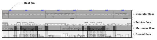
Figure 1.
Structure of the turbine (TBN) building and location of roof fans.
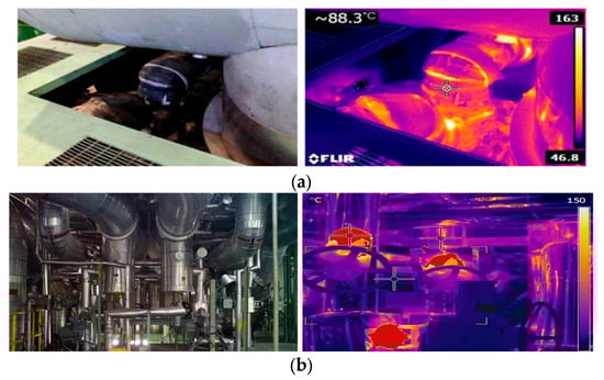
Figure 2.
Representative heat-generating power equipment in the turbine (TBN) building (a) High-intermediate pressure turbine (TBN) on the turbine (TBN) floor; (b) Main stop valve on the mezzanine floor.
2.2. Structure of the Turbine (TBN) Floor and Modeling
Turbines (TBNs), the core components of power generation, and multiple tanks for storing high-temperature steam are installed in the turbine (TBN) building. Therefore, high-temperature air is concentrated on the turbine (TBN) floor, and its condition needs to be improved. Consequently, we aimed to derive the results of heat accumulation within the turbine (TBN) floor using CFD.
As shown in Figure 3, we first modeled the layout of the turbine (TBN) floor. On the turbine (TBN) floor, there are two turbines (TBNs), the deaerator and the heater, which handle high-temperature and high-pressure steam, and the high-intermediate pressure turbine (TBN), which discharges high-temperature air. For ventilation, there are windows and roof fans. For natural ventilation, windows are installed on the front and the sides of the building, and the rear of the deaerator. For mechanical ventilation, there are eight roof fans that exhaust the high-temperature indoor air outside. The turbines (TBNs) require regular maintenance. Thus, as shown in the figure, a container that contains spare parts for turbine (TBN) replacement is located on the turbine (TBN) floor.
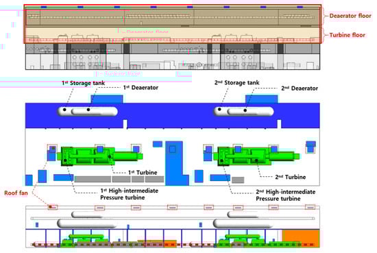
Figure 3.
Geometry modeling and structure of turbine (TBN) building.
2.3. Measuring the Temperature of the Main Heat-Generating Parts on the Turbine (TBN) Floor
As mentioned above, high-temperature heat accumulates in the turbine (TBN) building of coal-fired power plants due to many heat sources. To collect fundamental data for the computational analysis in order to mitigate the heat concentration phenomenon, we measured the temperature of the primary heat-generating components. The temperature and velocity data were measured and used as boundary conditions. To measure the temperature and flow rate of the incoming air, a TSI-9535 hot-wire anemometer was used. The surface temperature data of the heat-generating equipment were measured using an SDT-341 contact thermometer. Direct surface temperature measurement of the main stop valve and control valve is not possible. Therefore, a thermal imaging camera was used to measure the temperature of these heat-generating parts. The average temperature of the measured area was calculated and used as a boundary condition. As shown in Figure 4, the surface temperature of the heat-generating equipment was automatically recorded over an extended period using LabVIEW and K-type thermocouples.
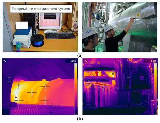
Figure 4.
Measurement of heat-generating surface temperatures inside the turbine (TBN) building (a) Automated temperature measurement LabVIEW system and surface thermometer; (b) Temperature measurement of heat-generating components using a thermal imaging camera.
The internal temperature of the turbine (TBN) building varies by season. Therefore, we measured the temperature of the primary heat-generating components during the summer, when the temperature is highest. The measured temperatures of the primary heat-generating components are demonstrated in Figure 5. The outdoor ambient temperature was measured over 3 months, and the surface temperature of the primary heat-generating components was measured once, as shown in the graph below. The highest surface temperature of the deaerator was 65.7 °C, while those of the heater and turbine (TBN) were 60.0 °C and 45.0 °C, respectively. Figure 6, below, shows the surface temperatures of the primary heat-generating components measured in real time from September to December. The surface temperature of the deaerator reached up to 70 °C and gradually decreased to 60 °C as winter approached. The deviation in outdoor ambient temperature was around 25 °C, and the maximum deviation in the surface temperature of the primary heat-generating components was 17 °C. Some measured temperatures dropped drastically on 30 November, when the operation was temporarily suspended for turbine (TBN) maintenance. It is practically impossible to measure the entire surface temperature of the heat-generating components in the turbine (TBN) building. Therefore, in this study, we selected representative points on the heat-generating surfaces and applied the average surface temperature of the equipment. Additionally, we used a thermal imaging camera to obtain the average temperature of the captured area and utilized these data for high-temperature areas that are otherwise impossible to measure.
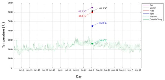
Figure 5.
Temperature measurement results of heating parts and outdoor air.
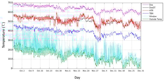
Figure 6.
Surface temperature measurement results of heating parts.
2.4. Boundary Conditions for the Computational Analysis
As mentioned above, the turbine (TBN) building’s ventilation system consists of windows and roof fans. However, the current ventilation facilities are insufficient to address all the issues caused by the internally concentrated heat. Therefore, we evaluated the efficacy of our recommendations for the improved ventilation system on the turbine (TBN) floor using a computational analysis. In the current study, we examined two ventilation facility improvement measures: (1) the installation of automatic ventilation windows and (2) the installation of additional roof fans. The boundary conditions for the computational analysis are listed in Table 1. We derived results from three cases in total. The first case evaluated the efficacy of the current ventilation facilities on the turbine (TBN) floor, generating results for the regular windows and eight roof fans. The second case examined the efficacy of installing fully opening automatic windows, which increased the amount of incoming air, while keeping the total number of roof fans at eight. In the third case, we evaluated the efficacy of installing automatic windows and additional fans at the rear of the deaerator. Two additional fans were installed, for a total of ten roof fans. We estimated the temperature of the primary heat-generating components of the power-generation equipment on the turbine (TBN) floor using the previously measured temperature data. As previously mentioned, the CFD boundary conditions are based on the measured values. The inlet on the turbine (TBN) floor is the window, which is set as a pressure outlet. The temperature of the air entering through the window is based on the ambient temperature measured in Figure 2. The roof fan is set as an outlet condition with a flow rate of 2900 m3/min, as shown in Table 1.

Table 1.
Boundary conditions for computational analysis.
The software used for the computational analysis is ANSYS-FLUENT R18.0. It is a commercial CFD software that solves the mass, momentum, and energy conservation equations using the finite volume method (FVM). In this study, we apply the three-dimensional incompressible flow continuity equation, momentum equation, energy equation, and turbulence model. The turbulence model used is the standard k-e (SKE) model. The SKE model is the most widely used engineering turbulence model in various industrial fields and is known for its high accuracy. The energy equation is used to output density, specific heat, and thermal conductivity based on temperature. Many composite properties are applied in the turbine (TBN) building. However, in this study, the material properties were simplified to concrete and aluminum. Table 2 shows the polynomial coefficients for air and the properties of the main materials as functions of temperature. Considering the convergence of the analysis, the geometry was simplified. The mesh for the turbine (TBN) floor modeling was generated by extracting the flow field area. Hexa/Tetra elements were used, and the total number of cells is 14,760,000.
Table 2.
Material properties and coefficients polynomial profile in terms of temperature.
2.5. Results of the Heat Concentration Phenomenon on the Turbine (TBN) Floor
We conducted a computational analysis to evaluate the heat concentration phenomenon on the turbine (TBN) floor and to recommend improvement measures. As previously stated, we selected three cases and derived the results, shown in Table 3 below.
Table 3.
Computational analysis results of heat concentration in turbine (TBN) building.
We visualized temperature contours and the volume of heat accumulation above 43 °C using a computational analysis. In the first case, which evaluated the effectiveness of the current ventilation system, we discovered that the high-temperature air of the high-intermediate pressure turbine (TBN) rose, and heat accumulated in its upper part. In particular, the heat was not discharged, and it accumulated near the deaerator. The capacity of the existing ventilation system was insufficient to discharge the internally generated heat, and there was a need to mitigate the heat accumulation by boosting the ventilation capacity. In the second case, where fully opening automatic windows were installed, the amount of incoming air increased, and the volume of accumulated heat was reduced. However, high-temperature air, emitted from the high-intermediate pressure turbine (TBN), caused heat to accumulate in some areas near the deaerator and the upper portion of the turbine (TBN). In the third case, where additional fans were installed at the rear of the deaerator, the amount of heat accumulated within the building was reduced. The fans externally emitted the heat accumulated in the deaerator, while the fully opening automatic windows increased the amount of incoming air. Although high-temperature heat accumulated at the top of the high-intermediate pressure turbine (TBN), the workspace of onsite workers remained at or below 30 °C. Malfunctions in core equipment and lubricant leakage occur due to the heat accumulation phenomenon on the turbine (TBN) floor. Therefore, there is a need to review the volume average temperatures in locations where core components are installed. Consequently, we noted the locations of the core components, and these are presented in Figure 7. The core components of the turbine (TBN) floor include the lower portions of the deaerator and heater, as well as the crane device on the upper portion of the turbine (TBN). These three components experience frequent malfunctions and lubricant leakage due to high temperatures. Thus, we reviewed the volume average temperatures of the surrounding areas and analyzed the effects of improving the ventilation system. The volume average temperatures are shown in Figure 8. In the first case of the current ventilation system, the volume average temperature of Heater 1 was 34.3 °C, and that of Heater 2 was 36.6 °C. The deaerator had the highest volume average temperature, 43.0 °C and 43.8 °C for Deaerator 1 and Deaerator 2, respectively. The volume average temperature of the crane was 43.9 °C. In the second case, we observed that the volume average temperature decreased by an average of −1.2 °C overall. In particular, the temperature decreased the most in the crane, by −1.4 °C. In the third case, where additional fans were installed on the deaerator, the volume average temperature decreased by an average of 6.6 °C, demonstrating the greatest effectiveness. In particular, the volume average temperature of Heater 2 decreased by 8.1 °C, showing the greatest effect. The mesh for the mezzanine floor modeling is generated by extracting the flow field area. Hexa/Tetra elements were used, and the total number of cells is 1,804,595.
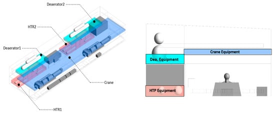
Figure 7.
Volume classification for output of volume average temperature results.
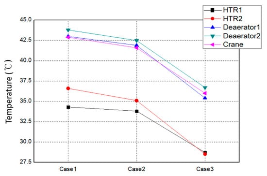
Figure 8.
Results of volume average temperature.
3. Analysis of the Heat Concentration Phenomenon on the Mezzanine Floor
3.1. Structure and Shape Modeling of the Mezzanine Floor
There are numerous high-temperature main and reheat steam pipelines on the mezzanine floor between the turbine (TBN) floor and the ground floor. Due to poor insulation conditions at the piping connections of the main stop valve, control valve, and high-intermediate pressure turbine (TBN) lagging, the heat radiation temperature is high. Since the emitted heat is not dissipated, heat accumulates, and the temperature inside the power plant rises. Heat can destabilize the operation of electronic devices and equipment near high-temperature components, causing malfunctions and lubricant leakage. Figure 9 depicts the mezzanine floor’s modeled form. There are two turbine (TBN)s surrounding the central unloading bay. Six main steam pipelines are connected to the main stop valve and control valve, which are predicted to have the greatest impact on temperature rise, and the turbine (TBN) condenser, the lower portion of the turbine (TBN), is located in the center. Between the ceiling of the main stop valve and the condenser, there is the high-intermediate pressure turbine (TBN) and three gratings, allowing high-temperature air around the main stop valve to rapidly reach the turbine floor. No windows that allow outside air to come in are installed, and there is a room on the right side of each unit. The second and third heaters are centered around the turbine, whereas the boiler feed water pump turbine (TBN) and the first heater are situated in the lower portion of the turbine (TBN) condenser. The majority of the floor is composed of gratings, allowing for the seamless inflow of air from the lower floor.
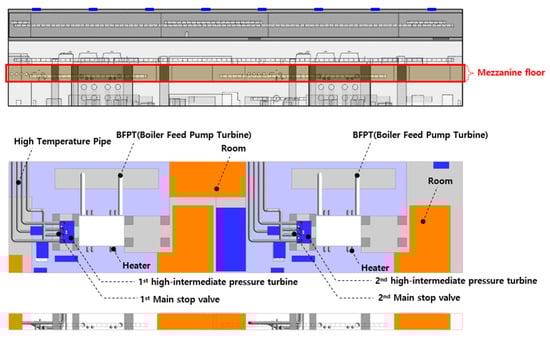
Figure 9.
Geometry modeling and structure of mezzanine floor.
3.2. Temperature Measurement of the Main Heat-Emitting Components on the Mezzanine Floor and Boundary Conditions for the Computational Analysis
The current study analyzed the heat flow on the mezzanine floor of the turbine (TBN) building under three-dimensional steady-state conditions. To investigate the effects of radiant heat on workers and electronic devices, we used the discrete ordinates (DO) model, one of the CFD radiation models. To set software boundary conditions, we measured the air flow rate and temperature, as well as the surface temperature of heated parts on the mezzanine floor, using an anemometer and a contact thermometer. Table 4 shows the results of the surface temperature measurements of the power-generation equipment on the mezzanine floor. Measurements were taken twice, in summer and winter, using a contact thermometer. Main stop valve pipe 1 recorded the highest temperature (a maximum of 110.0 °C in summer and 100.0 °C in winter), whereas the boiler feed water pump turbine (TBN) recorded the lowest temperature (a maximum of 42.0 °C in summer and 36.0 °C in winter).
Table 4.
Surface temperature of power generation parts on mezzanine floor.
3.3. Analysis Results of the Heat Concentration Phenomenon on the Mezzanine Floor
In the turbine (TBN) building, the mezzanine floor contains many control equipment devices, resulting in significant thermal damage due to high temperatures. Therefore, to analyze the causes, we examined the results for velocity field, temperature field, and radiant heat. The results for the internal flow field on the mezzanine floor during summer and winter are shown in Table 5, the temperature field results are shown in Table 6, and the radiant heat results are shown in Table 7. First, we observed the airflow through the HIP and MSV sections of each unit. On the mezzanine floor, flow stagnation was observed in most areas except around the main stop valve. The air around the high-temperature main stop valve heats up, rises due to natural convection, and is expelled to the TBN floor through the HIP. These flow characteristics on the mezzanine floor are similar regardless of seasonal changes.
Table 5.
Results of flow characteristics in summer and winter.
Table 6.
Results of temperature characteristics in summer and winter.
Table 7.
Results of radiant heat temperature characteristics in summer and winter.
Next, we examined the temperature field results on the mezzanine floor. In the summer, the average temperature on the surface of the HIP was 29.05 °C. The upper part of the HIP, where the internal air heated by the MSV is expelled, had a temperature of approximately 34.6 °C, which was higher than the surrounding temperature. These temperature results cannot be the cause of electronic device malfunctions and have minimal impact on the working environment of the workers. Therefore, it was assumed that most of the heated internal air was expelled through the HIP, having little effect on the temperature rise of the mezzanine floor. Similarly, in the winter temperature field results, most of the heated internal air rose to the ceiling and was expelled through the HIP. The temperature at the height of the employees and electronic equipment was lower than that of the ceiling. Most of the heated internal air was expelled to the TBN floor through the HIP and did not remain on the mezzanine floor. Consequently, the internal air heated by the high-temperature steam pipelines and the surface of the TBN condenser had little to no effect on the rise in indoor temperature. Therefore, the high-temperature air heated by the pipes and the main stop valve does not affect the room temperature through convection.
Lastly, we examined the radiant heat results on the mezzanine floor. Due to the radiant heat from the surfaces of the main stop valve, power equipment, and high-temperature steam pipelines, the radiant heat temperature in the workspaces and electronic device areas adjacent to Main Stop Valve 1 was 47.2 °C. In the workspace adjacent to the high-intermediate pressure turbine (TBN), the radiant temperature ranged from 50.8 °C to 51.4 °C. Particularly, in the area adjacent to the main stop valve where electronic control devices are installed, the temperature remained at a minimum of 50.8 °C regardless of the season. Consequently, the radiant heat falls within a temperature range that can affect the electronic devices and workers operating near the main stop valve for extended periods.
The average temperatures on the mezzanine floor are listed in Table 8. Based on the appropriate temperature of 38 °C set by the high-temperature work exposure standard (KOSHA CODE W 02-2007) [20], the ambient air temperature did not exceed the exposure standard, but the radiant heat did exceed this temperature. Consequently, radiant heat appeared to have had a significant impact on the increase in internal temperature.
Table 8.
Temperature characteristics result on mezzanine floor.
4. Results
The objective of the current study was to identify the causes of the temperature rise in the turbine (TBN) and mezzanine floors in the turbine (TBN) building, as well as to find solutions. An internal three-dimensional thermal fluid analysis was conducted using the commercial CFD software, ANSYS FLUENT R18.0. The results can be summarized as follows.
We evaluated the efficacy of installing automatic ventilation windows and additional heat exhaust fans on the deaerator floor to mitigate the heat concentration phenomenon on the turbine (TBN) floor. The installation of automatic ventilation windows decreased the temperature around the main power-generation equipment by 1.2 °C on average, while the installation of additional heat exhaust fans on the deaerator floor reduced the temperature by an average of 6.6 °C compared to the existing conditions. Installing heat exhaust fans at the rear of the deaerator floor, where heat accumulated the most, was found to be most effective in complementing the existing ventilation system. The turbine (TBN) building contains numerous high-temperature power generation equipment, and continuous maintenance is required for aging power plants. Installing many fans and windows to address the heat concentration phenomenon in the turbine (TBN) building can create difficulties in managing the winter temperatures and may not be an economical investment. Additionally, operating fans on a fixed cycle without considering ambient temperature changes can lead to frequent fan malfunctions. Therefore, to improve the heat concentration phenomenon in the turbine (TBN) building, identifying specific heat concentration locations and installing a small number of localized exhaust fans to expel radiant heat rising through the high-intermediate pressure turbine (TBN) and near the deaerator can significantly reduce temperatures and ensure the stable operation of the internal power generation equipment.
On the mezzanine floor, we found that the air temperature, heated by the high temperatures of the pipes and condenser wall surfaces, did not have a significant effect on the increase in indoor temperature. Heated indoor air around the main stop valve and the high-temperature power apparatus was discharged through the high-intermediate pressure turbine (TBN) affixed to the ceiling. Since the majority of the floor was composed of gratings, cooler outdoor air entered, and the temperature at the workers’ locations was not high. Due to the fluidic characteristics, the cause of the temperature rise was not identified. The radiant heat emitted from the surface of the high-temperature power plant locally led to an increase in the perceived temperature for onsite workers and malfunctions in the surrounding electronic devices. The high temperature around the main stop valve heats the surrounding air, and the heated air rises to the upper high-intermediate pressure turbine (TBN). Therefore, it was confirmed that this does not significantly affect the temperature rise on the mezzanine floor. In the case of radiant heat, temperatures of at least 50.8 °C were maintained regardless of the season, which could cause malfunctions in the control devices adjacent to the main stop valve and seriously affect onsite workers who work for extended periods. Notably, the radiant heat exceeded the KOSHA CODE standards for high-temperature work. Therefore, installing radiation shields and insulation on the surface of the main stop valve, and controlling valve pipe connections on the mezzanine floor, will enable more stable operation of the equipment.
Author Contributions
Conceptualization, M.-L.C.; methodology, M.-L.C. and S.-B.L.; software, M.-L.C.; validation, M.-L.C. and S.-B.L.; formal analysis, S.-B.L.; investigation, M.-L.C. and S.-B.L.; resources, S.-B.L.; data curation, M.-L.C.; writing—original draft preparation, M.-L.C. and S.-B.L.; writing—review and editing, M.-L.C. and S.-B.L.; visualization, M.-L.C.; supervision, S.-B.L.; project administration, M.-L.C. All authors have read and agreed to the published version of the manuscript.
Funding
This research received no external funding.
Data Availability Statement
The data presented in this study are available on request from the corresponding author (Security of critical national facilities).
Conflicts of Interest
The authors declare no conflict of interest.
References
- Cha, K.Y.; Shin, K.Y. Analytic Study on Energy Demand Management State in Industrial Sector. J. Energy Clim. Chang. 2021, 16, 89. [Google Scholar] [CrossRef]
- Um, B.H.; Ahn, C.S. An Economic Analysis of the Effluent Heat Supply from Thermal Power Plant to the Farm Facility House. Korean J. Chem. Eng. 2018, 56, 6. [Google Scholar] [CrossRef]
- Kim, D.H.; Choi, H.S. State of the Art in Life Assessment for High Temperature Components Using Replication Method. J. Korean Soc. Nondestruct. Test. 2010, 30, 489. [Google Scholar]
- Kim, M.J.; Xiao, X.; Lee, D.B. Study of High Temperature Corrosion of Fe-Cr-W Steel in Coal-Biomass Co-firing Power Plant Environment. J. Surf. Sci. Eng. 2019, 52, 251. [Google Scholar] [CrossRef]
- Lee, Y.B. Development of Test Code of MTV & ETV for TPP. J. Drive Control 2011, 8, 28. [Google Scholar] [CrossRef]
- Kim, H.J.; Jeong, Y.G.; Park, J.J. Development of Small-Specimen Creep Tester for Life Assessment of High Temperature Components of Power. Trans. Korean Soc. Mech. Eng. 2000, 24, 2597. [Google Scholar] [CrossRef]
- Bettge, D.; Klinger, C.; Klingbeil, D.; Eberle, A. Investigations on the breakdown of a heat recovery steam generator during the initial operation run. Eng. Fail. Anal. 2014, 43, 253. [Google Scholar] [CrossRef]
- Takahashi, T.; Koda, E.; Nakao, Y. Development of the performance deterioration diagnosis method to thermal power plant. Proc. Int. Conf. Power Eng. 2010, 5, 249. [Google Scholar] [CrossRef][Green Version]
- Liao, G.S. Analysis of Power Plant Deaerator Under Transient Turbine (TBN) Loads. J. Eng. Gas Turbine (TBN)S Power 1973, 95, 171. [Google Scholar] [CrossRef]
- Kim, J.W.; Jeong, B.Y. Comparison of Occupational Risk Factors and Health-related Problems between Office Workers and Production Workers in the Automobile Manufacturing Industry. Anal. J. Ergon. Soc. Korea 2021, 40, 199. [Google Scholar] [CrossRef]
- Hole, J.A.; Pande, M. Worker productivity, occupational health, safety and environmental issues in thermal power plant. In Proceedings of the IEEE International Conference on Industrial Engineering and Engineering Management 2019, Hong Kong, China, 8–11 December 2009. [Google Scholar] [CrossRef]
- Danquah, R.; Mensah, G.; Senyo, W.; Davis, F. Assessment of hazard recognition performance of thermal power plant workers: A case study of a combined cycle power plant. Cogent Eng. 2023, 310, 50. [Google Scholar] [CrossRef]
- Chen, M.L.; Chen, C.J.; Yeh, W.Y.; Huang, J.W.; Mao, I.F. Heat Stress Evaluation and Worker Fatigue in a Steel Plant. AIHA J. 2003, 64, 352. [Google Scholar] [CrossRef]
- Du, J.; Li, Y.; Zhao, Y.; Da, Y.; Che, D. Numerical Study of Supercritical Opposed Wall-Fired Boiler Furnace Temperature and High-Temperature Heating Surface Stress under Variable Load Operation. Energies 2024, 17, 663. [Google Scholar] [CrossRef]
- Zhang, H.; Jia, J.; Wang, N.; Hu, X.; Tu, S.-T.; Zhou, S.; Wang, Z. Development of On-Line Monitoring Systems for High Temperature Components in Power Plants. Sensors 2013, 13, 15504–15512. [Google Scholar] [CrossRef]
- Guo, X.; Xia, L.; Zhao, G.; Wei, G.; Wang, Y.; Yin, Y.; Guo, J.; Ren, X. Steam Temperature Characteristics in Boiler Water Wall Tubes Based on Furnace CFD and Hydrodynamic Coupling Model. Energies 2022, 15, 4745. [Google Scholar] [CrossRef]
- Wang, H.; Zhai, J. Simulation Analysis of High Radiant Heat Plant Cooling and Endothermic Screen Waste Heat Recovery Performance Based on FLUENT. Energies 2023, 16, 4196. [Google Scholar] [CrossRef]
- Brzezińska, D.; Brzezińska, M. Performance-Based Solutions of Thermal and Smoke Control Ventilation in Industrial Power Plant Buildings. Energies 2022, 15, 7396. [Google Scholar] [CrossRef]
- Yang, Y.; Cai, Y.; Huang, Y.; Liu, Z.; Xu, F. Fuzzy Optimization Research on Thermal Comfort of Atrium Space in Ofice Buildings under the Natural Ventilation Environment. J. Hum. Settl. West China 2022, 37, 119–125. [Google Scholar]
- Occupational Safety and Health Agency. Available online: https://kosha.or.kr/kosha/intro/jeonbukBranch_A.do?mode=download&articleNo=350706&attachNo=197677 (accessed on 10 July 2023).


Disclaimer/Publisher’s Note: The statements, opinions and data contained in all publications are solely those of the individual author(s) and contributor(s) and not of MDPI and/or the editor(s). MDPI and/or the editor(s) disclaim responsibility for any injury to people or property resulting from any ideas, methods, instructions or products referred to in the content. |
© 2024 by the authors. Licensee MDPI, Basel, Switzerland. This article is an open access article distributed under the terms and conditions of the Creative Commons Attribution (CC BY) license (https://creativecommons.org/licenses/by/4.0/).