Article

Experimental Investigation of Use of Monoethanolamine with Iron Oxide Nanoparticles in a 10 kg per Day Pilot CO2 Capture Plant: Implications for Commercialization

by
Sriniwasa Prabhu
*,
Govindaradjane Soupramaniane
and
Raman Saravanane
Department of Civil Engineering, Puducherry Technological University, Puducherry 605014, India
*
Author to whom correspondence should be addressed.
Submission received: 10 March 2025 / Revised: 23 April 2025 / Accepted: 25 April 2025 / Published: 27 April 2025
(This article belongs to the Section Carbon Cycle, Capture and Storage)

Abstract

:
This study explores enhancements in CO2 capture and release using monoethanolamine (MEA) combined with iron oxide nanoarticles (IONPs) in a 10 kg per day pilot CO2 capture plant. Previous studies highlighted the potential of nanoparticle additives to improve CO2 capture via modeling and batch experiments; however, robust experimental evidence at the pilot scale is necessary for commercialization. This pilot plant employed a thermal swing process using synthetic CO2–flue gas mixtures, conditioning systems, and Programmable Logic Controller (PLC)-based controls for heating, operation, and data acquisition. IONPs, synthesized through chemical precipitation and characterized by XRD and HR-SEM, were integrated into MEA at concentrations of 0.0001% w/v (1 ppm), 0.001% w/v (10 ppm), and 0.002% w/v (20 ppm). Their electromagnetic properties enhanced mass transfer during absorption and significantly reduced heat demand during stripper desorption. Higher concentrations of IONPs decreased desorption temperatures by up to 7 °C, resulting in estimated energy savings of approximately 10–15%, while achieving CO2 loading rates up to 0.34 mol CO2/mol MEA. Structural stability of the IONPs was confirmed via XRD and HR-SEM analyses following extended thermal cycling. Utilizing a common solvent and abundant catalyst, these demonstrated improvements underscore the practical scalability and commercial viability of MEA-based CO2 capture catalyzed by IONPs, particularly suitable for deployment in large-scale CO2 capture systems in high-CO2-emitting industries.

Graphical Abstract

1. Introduction

The urgent need to tackle climate change calls for innovative solutions, with carbon capture and storage (CCS) emerging as a key technology to mitigate rising greenhouse gas emissions. Among CCS methods, post-combustion capture (PCC) is particularly viable due to its retrofitting capability into existing industrial infrastructures, offering an effective way to reduce CO2 emissions. Major contributors to anthropogenic CO2 emissions include the coal, cement, and steel industries [1].
PCC captures CO2 after combustion, enabling either utilization or secure geological sequestration. Countries like India are actively pursuing emission reductions and sustainable practices. The Intergovernmental Panel on Climate Change (IPCC) emphasizes urgent action to limit global warming. For rapidly industrializing nations, adopting PCC aligns with international climate goals and Intended Nationally Determined Contributions (INDCs), supporting sustainable development and climate resilience [2].
Initial decarbonization efforts such as energy efficiency and renewable energy integration are underway. However, IPCC and IEA reports suggest that Net-Zero CO2 targets are unattainable without direct capture technologies [3]. Monoethanolamine (MEA), a primary amine with high CO2 affinity, is a widely used solvent in PCC applications [4,5]. MEA absorbs CO2 from flue gasses and is regenerated via thermal processes, releasing the captured CO2 for reuse or storage [2,6,7].
MEA is favored for its cost-effectiveness, wide market availability, and minimal logistical constraints [7,8,9]. As a primary amine produced on a large scale, MEA is affordable and consistently available across industries such as detergents and textiles, reducing potential supply chain issues [10].
To further enhance PCC efficiency, pilot plants are gaining traction over batch systems. Unlike batch reactors, pilot plants provide real-time data, enabling precise control, improved scalability, and deeper insights into the dynamic behavior of MEA in industrial applications [11,12]. These factors make pilot plants an invaluable tool in optimizing CO2 capture processes for large-scale industrial implementation.
To overcome several challenges of using MEA as a solvent for CO2 capture [13,14], several catalysts and process design modifications are being adopted across the globe. In one such novel approach, iron oxide nanoparticles (IONPs) are engaged with MEA-based solvents to enhance CO2 capture and release [15,16]. IONPs typically based on magnetite (Fe3O4) are extremely abundant and heavily employed at industrial scales for pigments, catalysts, and biochemical agents across the globe. As per a recent market analysis report published in 2025, the global production of iron oxide nanopowders already exceeds 20,000 tons annually, with major production capacity in Asia [17]. The synthesis of IONPs is also relatively simple and readily scalable. Thus, from a supply chain perspective, IONPs are readily available, with ease for large scale applications. As a catalyst, only <1% w/v of IONPs will be used, and any incremental material cost is also negligible at an industrial scale.
While using IONPs with MEA solvent during the absorption stage, an applied voltage mobilizes ferromagnetic IONPs, increasing the interaction surface between gaseous CO2 and the liquid MEA solvent. This magnetic actuation enhances Brownian motion and micro-convection. These effects disrupt the gas–liquid boundary layer, improving mass transfer and CO2 absorption efficiency. Simultaneously, IONP movement prevents solvent agglomeration, maintaining a stable reaction environment.
In the desorption stage, the ferromagnetic properties of IONPs enable internal heating when exposed to a varying magnetic field. Heat is generated via hysteresis losses (ferromagnetic) and relaxation losses (Néel and Brownian) in superparamagnetic particles [18]. This inductive heating warms the MEA solvent from within, bypassing inefficient convective wall heating and achieving up to 79% higher efficiency [19]. It supplements external heat, reducing total energy demand for CO2 stripping.
A study using nano-hematite (Fe2O3) with a blended amine solvent yielded a CO2 absorption rate of 19% and a CO2 desorption rate of 47% using a 100 mL glass CO2 bubbler reactor [20]. Fe3O4 particles were functionalized with nanoparticles of arginine, histidine, and glycine and showed 23%, 17%, and 10% increases in CO2 absorption capacity, respectively, and CO2 desorption enhancements of 48.2%, 47.2%, and 46.1% at 70 °C in a bubble column reactor [16]. The CO2 solubility in amine-functionalized Fe3O4 improved by 77%, and regeneration energy was reduced by 23.2% by employing a sonication-based regeneration procedure [21]. The Fe3O4@UiO-66–SO4 nanocatalyst required 40 to 50% of the usual heat energy for CO2 regeneration compared to typical MEA solvents, ascertained through Thermogravimetric Analysis at the lab scale [22]. Using a gas diffuser reactor column setup at the lab scale, 10% MDEA and 0.1% w/v Fe3O4 improved the CO2 loading rate by 36% and efficiently stripped CO2 at the gas phase outlet, achieving 44.2% vol of CO2 [23].
In a wet-wall absorber with Fe3O4 nanofluid under an external magnetic field, researchers observed a 22% increase in CO2 flux and a 59% higher mass transfer coefficient compared to non-field conditions [24]. In another study, with both bubble and film columns, 40–50% faster CO2 absorption was reported when a magnetic field was applied to blended amine solvents with ferro nanofluid [25].
Several bench-top and batch-type studies have shown promising process enhancements by using IONPs in amine solvent for CO2 capture [18,19,20,21,22,23]. The amine-based pH control agent used in Pressurized Water Reactors (PWR) of power plants affects the iron oxide surface charge properties [26]. It has also been observed that in a bubble column reactor experiment for CO2 capture, Fe3O4 nanoparticles likely suffered particle agglomeration when compared to the same nanoparticles functionalized with aspartic acid and Lysine [27]. During the industrial application of IONPs with MEA solvent for CO2 capture, the stability of IONPs could suffer during continuous thermal cycles and CO2 reactivity. A pilot plant study could help determine the stability of IONPs upon long-term usage for CO2 capture.
The successful synergy of using abundant, readily available, and simple IONPs with traditional amine solvents like MEA is not far sighted as per several recent research studies. However, a continuous reactor experiment with a pilot plant could provide valuable insights on the use of IONPs with amine solvents for CO2 capture plants. In this study, iron oxide nanoparticles are used with MEA solvent in a pilot CO2 capture plant of 10 kg per day capacity to characterize CO2 absorption and desorption behaviors. The study also quantifies the suitability and stability of iron oxide nanoparticles for the specified application.

2. Materials and Methods

2.1. Synthesis of Iron Oxide Nanoparticles
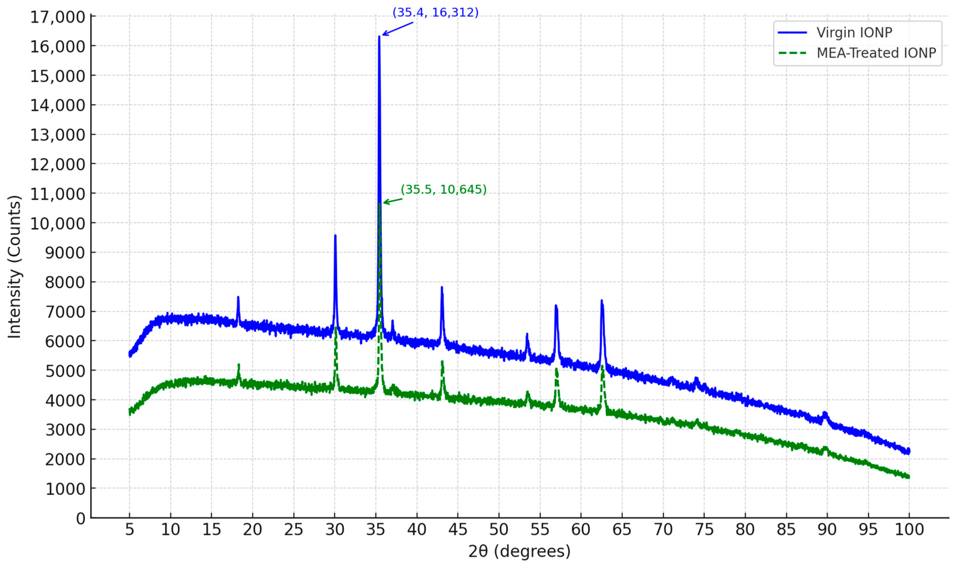
In this study, we synthesized iron oxide nanoparticles (IONPs) using the chemical precipitation method, a preferred approach due to its simplicity and scalability for potential large-scale deployments. This method, as detailed in [15], was adapted and scaled to produce the necessary quantity of IONPs for the proposed experiments, totaling to the tune of 100 g.
Multiple batches were required to synthesize the amount of IONPs required for this study. Each batch involved dissolving 8 g of hydrated ferrous sulfate (FeSO4·7H2O) and hydrated ferric chloride (FeCl3·6H2O) in 600 mL of double distilled water. The solution was then heated to 80 °C using a controlled heating setup. Once the desired reaction temperature was reached, 48 mL of a 27% ammonium hydroxide (NH4OH) solution was added drop by drop using a burette. The addition of the alkaline solution was carefully controlled, and the mixture was continuously stirred using a magnetic stirrer for 40 min to ensure uniform precipitation.
The process resulted in a brown precipitate, which was cooled overnight to ensure complete precipitation of the nanoparticles. The precipitate was then filtered to separate the solid nanoparticles from the liquid phase. The filtered nanoparticles were thoroughly washed with distilled water to remove any residual reactants and then with rubbing alcohol to support the drying process. This filtered precipitate was dried in an oven at 100 °C for 24 h to obtain dry iron oxide nanoparticles.
To ensure consistency and prevent moisture build up, the synthesized IONPs were mixed well and stored in a dry state. Before each experimental use, the nanoparticles were dried in an oven at 100 °C for at least 30 min to eliminate any accumulated moisture. This step was crucial to normally minimize the effect of contaminants and environmental parameters on each produced batch of nanoparticles and make it ready to mix with monoethanolamine (MEA) solvent for CO2 capture.
This synthesis process can be easily scaled and reproduced as an industrial process, which ensures its applicability for industrial-scale production, making it a viable approach for future CO2 capture and sequestration technologies. By maintaining strict control over the synthesis parameters and ensuring thorough drying of the nanoparticles, we achieved a consistent and reliable product for our research objectives.

2.2. XRD Analysis

The IONP sample was prepared at room temperature in powdered form for XRD analysis. Bragg’s law relates the wavelength and diffraction angle of the X-ray to the crystal structure of a lattice. The intensity peaks at different diffraction angles (2θ) can help identify the composition and size of atoms using the following Equation: nλ = 2 d sin θ, where ‘n’ is the order of diffraction, ‘λ’ is the wavelength of X-rays, ‘d’ is the interplanar spacing, and ‘θ’ is the diffraction angle.
The typical peak 2θ values (for Cu Kα radiation) for magnetite are 30.1° (220), 35.5° (311), 43.1° (400), 53.4° (422), 57.0° (511), and 62.6° (440). The (311) reflection is the most intense peak and is the key identifier in XRD analysis.

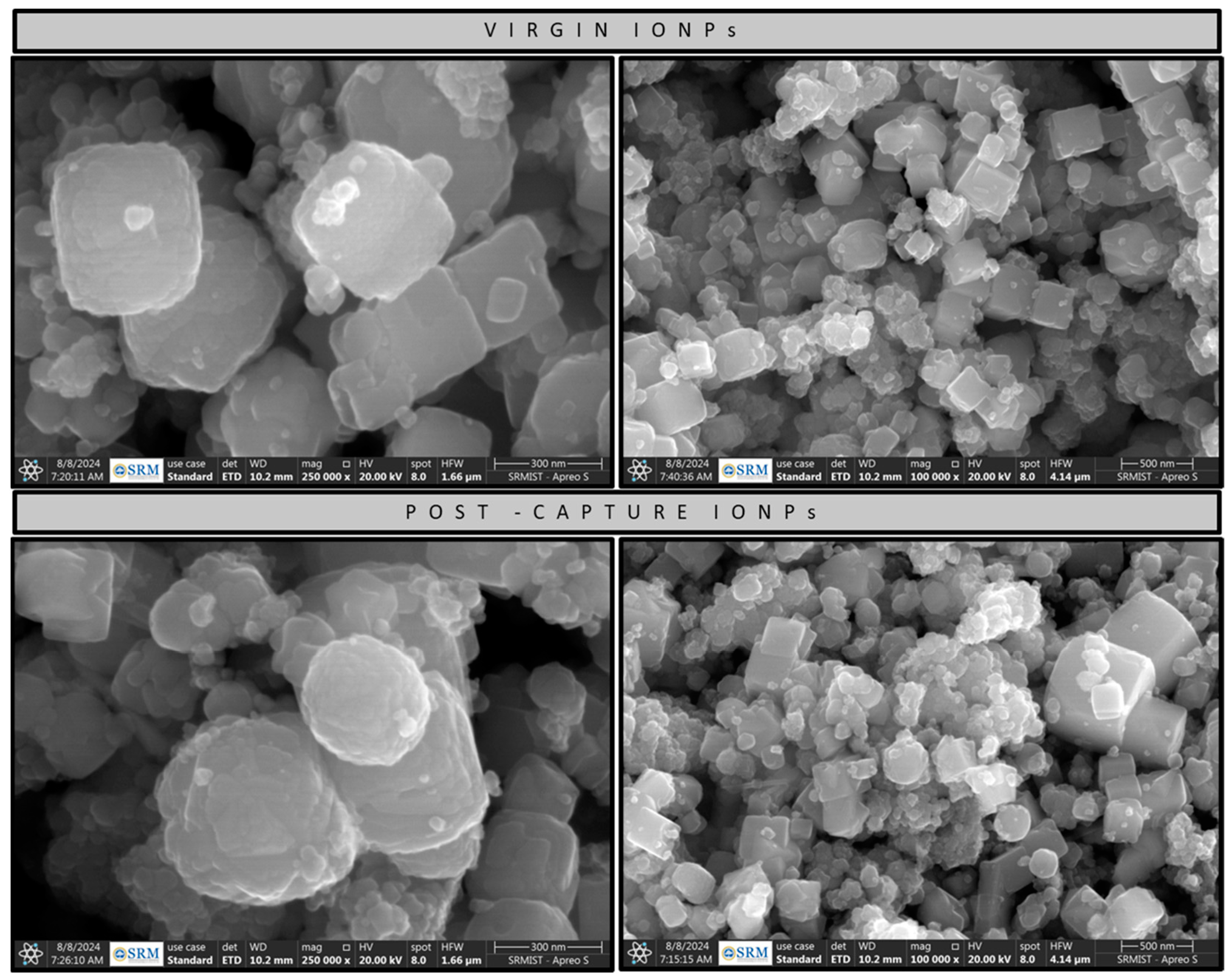
2.3. HR-SEM Analysis

High-Resolution Scanning Electron Microscopy (HR-SEM), an advanced imaging technique, was employed to investigate the morphological features, size distribution, and surface characteristics of both virgin and post-capture iron oxide nanoparticles (IONPs). Understanding these structural properties is essential, as they significantly influence the efficacy of IONPs in CO2 capture applications. HR-SEM analysis provided detailed insights into particle size and shape, identified agglomeration tendencies, and assessed dispersion uniformity within the nanoparticle samples before and after CO2 capture processes.

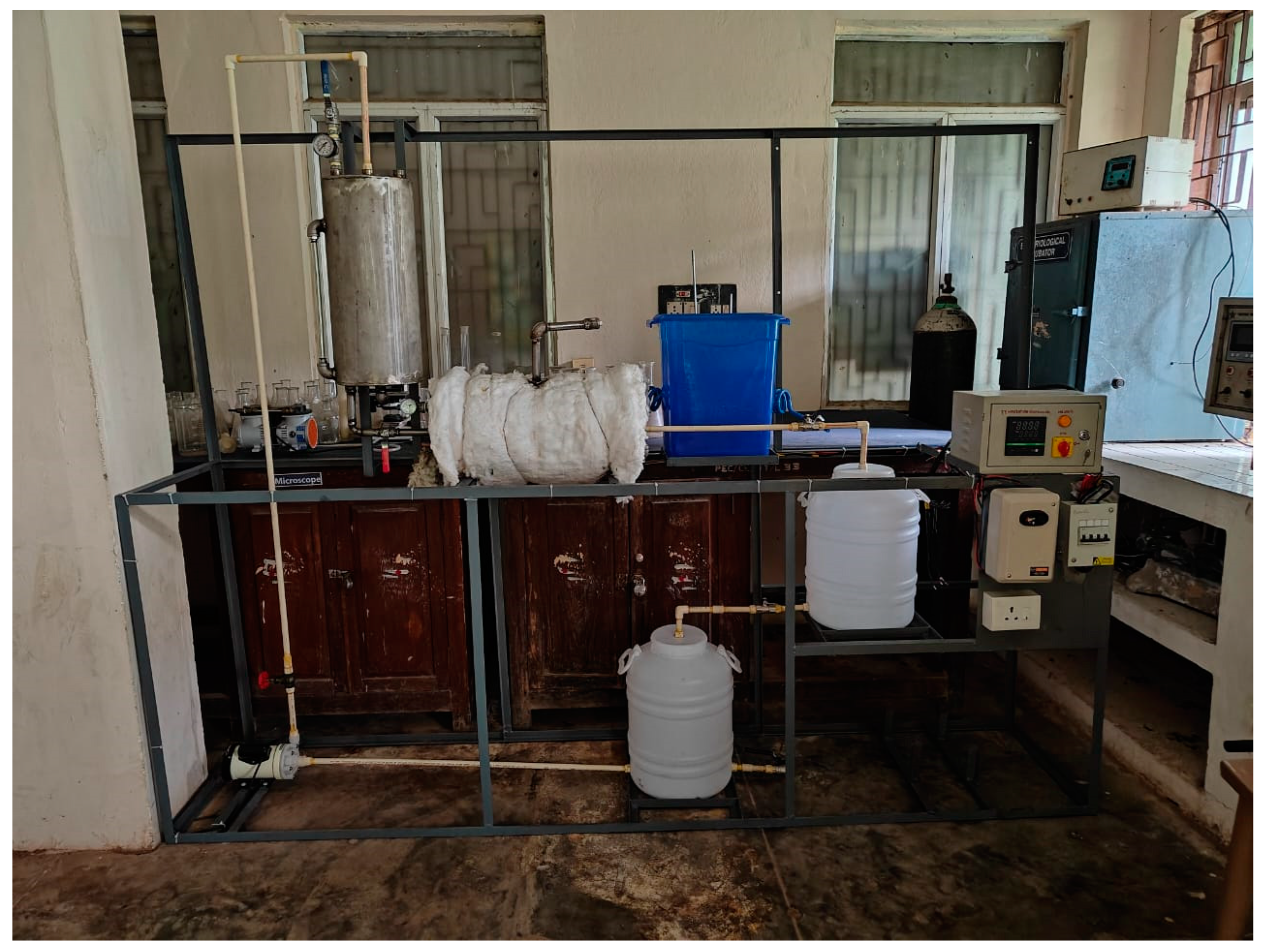
3. Experimental Setup

3.1. Materials and Reagents

Monoethanolamine (MEA), with a purity of 99%, was supplied by Pon Pure Chemicals, India. Commercial-grade CO2 with a purity of 99% was procured from a local. The desired concentrations of MEA were prepared using double-distilled water. The source of air required to produce 5–20% CO2 was obtained using a lab vacuum pump with a capacity of 50 lpm.
The gas flow levels of both the air and CO2 were regulated using rotameters obtained from S.Y. Industries, Thane, India. Pressure measurements were carried out using Janatics pressure gauges with a 10 bar capacity and a resolution of 0.5 bar. Temperature was monitored with gauges capable of measuring up to 150 °C, with a resolution of 2.5 °C. In order to access the CO2 loading rate, the following chemical reagents were used: methanol (99% purity), sulfuric acid solution, sodium hydroxide solution, and thymolphthalein indicator.

3.2. CO2 Absorption and Desorption–Pilot CO2 Capture Plant

A schematic of the 10 kg/day pilot CO2 capture plant is shown in Figure 1. It includes components such as synthetic CO2–flue gas supply, a solvent recirculation system, a packed absorption reactor, a desorption reactor, a desorbed CO2 vent connected to an evaporative cooler, ceramic band heaters with a PLC thermostat, and temperature/pressure monitors. Reactor pressures were not controlled but monitored to ensure positive flow of the CO2–air mix and MEA solvent.
The absorber operates in counter-current mode using a packed bed, ensuring efficient CO2 uptake by the solvent. CO2-rich solvent is then directed to a stripper, where external heat facilitates desorption. The regenerated lean solvent is recirculated to the reservoir for reuse, while stripped CO2 is collected at the stripper top for analysis or utilization. The CO2–flue gas is introduced at the bottom of the absorber via pneumatic tubing. Rotameters regulate CO2 and air flow (10 lpm CO2 with 0.5 lpm resolution; 50 lpm air with 1 lpm resolution) to achieve 5–20% CO2 concentration. Each test is run over ~1000 thermal sorption–desorption cycles across 5 days, using the same solvent batch to average out fluctuations. Solvent recirculation is achieved using a polypropylene (PP) pump.
The SS 304 absorber is cylindrical, with a CO2 inlet at the bottom, solvent outlet to the stripper, and solvent spray inlet at the top. Mesh random packing increases residence time. The stripper vessel, a horizontal SS 304 cylinder, is heated externally with ceramic bands (up to 150 °C) and insulated with rock wool. Gauges monitor temperature, pressure, and fluid levels. Solvent flow is level-controlled to ensure adequate residence time. Both vessels are wrapped with 1 mm thick, 0.3 m high copper coils powered by two 9 V batteries (2 A current) to activate IONPs catalytically. Multiple SS 304 gate valves regulate flow. The PLC-controlled thermostat ensures accurate heat regulation and safety. The photographs of the pilot plant are shown in Figure 2.

3.3. Nanoparticle Integration

Iron oxide nanoparticles (IONPs) were added to a 30% v/v MEA solution at 0.0001% (1 ppm), 0.001% (10 ppm), and 0.002% (20 ppm) w/v. After thorough 20 min stirring, a homogeneous nanoparticle–MEA mix was achieved and used as the lean CO2 solvent. To maintain dispersion and catalytic activity, copper coils around the reactors generated a weak alternating magnetic field (~2 A via 9 V batteries). This electromagnetic field enhanced IONP mobility, improving CO2 absorption through localized mixing and reducing settling. During desorption, in situ thermal activation aided stripping. This strategy ensured catalyst stability and improved mass transfer and energy integration throughout absorption–desorption cycles.

3.4. CO2 Loading Measurement in Solvent–UOP Method 829-82

The UOP Method 829-82 [28] facilitated systematic calculation of loading rates of CO2 with MEA solvent. The CO2 loading rate of a sample is the ratio of mol of CO2 present in a mol of MEA that denotes the total uptake of CO2 by one mol of MEA. The CO2 desorption rate is the number of moles of CO2 present in the MEA sample before and after the stripper vessel, i.e., number of moles of CO2 desorbed from the solvent due to the applied heat energy. The IONPs were filtered out of the MEA solvent before subjecting it to loading measurement titration. It is a method used for titrimetric determination of CO2 in ethanolamine solutions. The CO2 loaded samples were dissolved in anhydrous methanol to estimate loading rates. This solution was then titrated against a standard methanolic sodium hydroxide (MeONa) solution to calculate the CO2 content. Hence, this method is also referred to as the MeONa method.
A methanol solution of 100 mL is taken in a 500 mL Erlenmeyer flask and thymolphthalein indicator. Then, 0.5 M methanolic sodium hydroxide solution is prepared and titrated against this methanol solution to a light blue color while constantly stirring the solution in the flask. This titrant value is recorded as B. This represents the methanol blank value.
Now, 10 mL of the CO2-loaded sample is taken in a pipette and added to the Erlenmeyer flask. The light blue color disappears. This sample and methanol solution is now titrated against 0.5 M MeONa solution until a light blue color appears. This titrant value is recorded as A. The CO2 content of the sample can now be calculated using the following formula:
M o l   o f   C O 2 M o l   o f   M E A = 0.0195 × 3.2 × A B × M V
where A—total volume of standard MeONa added in mL; B—volume of standard MeONa added for methanol blank in mL; M—molarity of MeONa; and V—sample volume in mL.

4. Results and Discussion

4.1. Characterization of IONPs

4.1.1. XRD Characterization

X-Ray Diffraction (XRD) analysis facilitates assessment of structural properties of iron oxide nanoparticles (IONPs) before and after their usage in a pilot CO2 capture plant with monoethanolamine (MEA) solvent. During the CO2 capture process, the MEA solvent mediated with IONPs is subjected to high temperatures and chemical interactions for 1000 repetitive cycles. The unique electromagnetic properties of the IONPs integrated into MEA solvent help with the efficacy of CO2 capture and separation. XRD is utilized to study the impact on the crystallographic structure, phase purity, and stability of IONPs though the capture and regeneration cycles.

4.1.2. Virgin IONP Characterization

The characterization of virgin IONPs synthesized is required to set a baseline to quantify the deterioration of IONPs when used for the CO2 capture process with MEA solvent. The synthesized IONPs are composed of magnetite particles (Fe3O4), whose distinct peaks at 2θ of 35.4 were observed in the XRD analysis, as seen in Figure 3. The background corrected intensity peaks dataset is included in the Supplementary Information. The sharp peak of 4157 cts at 2θ of 35.4 indicates a highly crystalline structure.
The surface driven interactions of the synthesized nanoparticles can be effectively determined using the Scherrer Equation:
D = β c o s θ K λ  
where D—crystallite size (nm), K—shape factor (0.9), λ—X-Ray wavelength (1.5406 Å for Cu Kα radiation), β—FWHM (in radians), and θ—Bragg angle (in radians). For virgin IONPs, the most intense peak occurred at 2θ = 35.4375°, with a full width at half maximum (FWHM) of 1.0391°. This results in a crystallite size of 8.03 nm, confirming the nanoscale nature of the particles suitable to enhance the Brownian motion and interfacial mass transfer of CO2 between the synthetic flue gas and MEA-IONP solution.

4.1.3. Post-CO2 Capture Process IONP Characterization

After being used in the pilot plant for CO2 capture and regeneration, the MEA–IONP mixture was filtered to separate the IONPs from the solvent. The recovered nanoparticles were then air-dried and subjected to XRD analysis to assess any changes in their crystallographic structure. The post-usage XRD patterns were compared with baseline data to detect any phase transformations, changes in crystallinity, or structural degradation that might have occurred during the absorption–desorption cycles.
The magnetite (Fe3O4) was still the significant component in the lattice structure, with a sharp peak of 4368 cts at 2θ of 35.5. All the major peaks retained the same diffraction angles and peak intensities when analyzed after the absorption–desorption cycles.
For the prominent peak at 2θ = 35.5098° and a narrowed FWHM of 0.5196°, using the Scherrer equation, the crystallite size was determined to be 16.05 nm. The two-fold increase in crystallite size indicates clear coalescence due to thermal impact during desorption but does not indicate significant phase change after 1000 cycles of operation.

4.1.4. Impacts of Crystallite Size of IONPs on CO2 Capture Process Using MEA as Solvent

The XRD analysis data of virgin and post capture IONPs indicated that no new phases were identified, with diffraction patterns remaining stable, including the magnetite identity and structural integrity. The synthesized IONPs possessed rich crystallographic stability and showed negligible degradation when used for CO2 capture in MEA solution in a thermal swing process.
The doubling growth of crystallite size from 8.03 nm (virgin) to 16.05 nm (post-capture) could lead to a reduction in surface area that supports the mass transfer phenomenon for longer cyclic periods. However, it is clear that the growth of the crystallite size of IONPs post capture improves thermal stability and ensures their suitability for long-term cyclic use. This presents a strong case for an effective additive to MEA solution in a process where thermal resistance and magnetic properties play a pivotal role.

4.1.5. HR-SEM Characterization

The HR-SEM images of virgin and post capture IONPs at various scales, compared side-by-side, can be found in Figure 4 and Figure 5. Virgin IONPs display a relatively uniform cubic structure, representing well-crystalized IONPs with sharp and discrete edges. Individual particles are clearly visible, with minimal aggregation. The particle surfaces are also fairly smooth, denoting well-formed crystal planes.
Post-capture IONPs are aggregated with round edges, showing minimal cubic structure possibly due to cyclic thermal thawing during the absorption–desorption cycles. There are several sightings of large clusters and amorphous coatings on some particles. The surfaces show partial sintering which is due to thermal impact during the desorption stage CO2 Capture process. Some particles are present in larger forms, which also confirms crystallite size growth, determined using the Scherrer equation in previous sections. Since there is no apparent phase change or total change in structure, these IONPs can be used for longer cycle times for CO2 capture using MEA solvent in a thermal swing process.
Energy-Dispersive X-Ray Spectroscopy (EDS) performed in conjunction with HR-SEM analysis revealed the elemental composition in IONPs in both virgin and post-capture scenarios. The elemental compositions can be found in Table 1. The values indicate that the presence of the Fe element, which carries the electromagnetic property facilitating the Brownian motion, has not deteriorated to a significant extent in post-capture IONPs. Virgin IONPs held 66.66% of the Fe element, and post capture, the value was still at 65.04%. During the CO2 capture process, contaminants like Na and S were introduced into the IONPs post capture. This could be from the water used to dilute the MEA to 30% in the CO2 capture process.

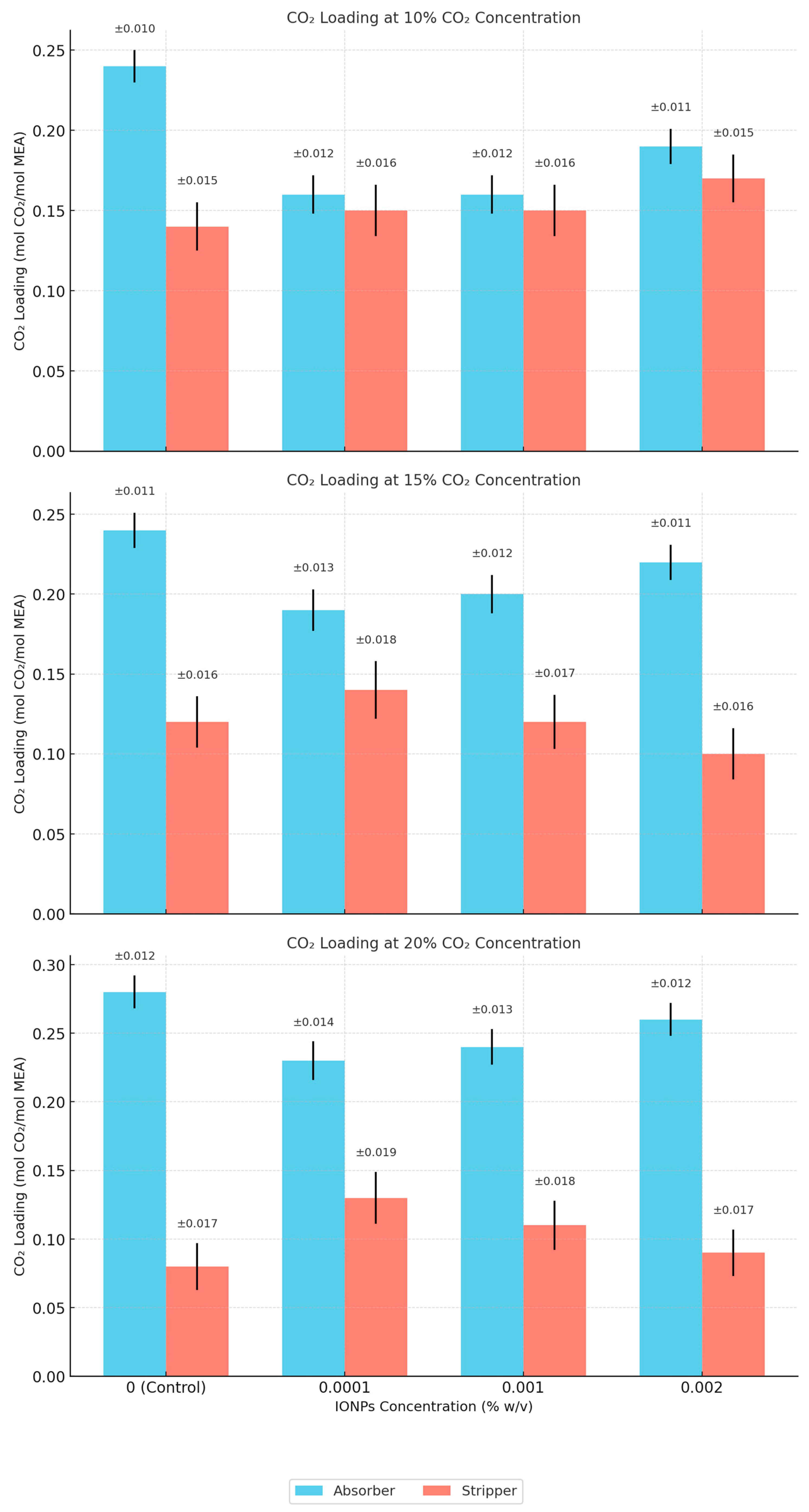
4.2. CO2 Capture and Separation

The pilot plant was used to test all parameter variations listed in Table 2 including a control run with 30% MEA and no IONPs (0% w/v). Target CO2 concentrations (10%, 15%, and 20%, per Table 3) were achieved by diluting pure CO2 with ambient air using a vacuum pump. CO2 loading after absorption and stripping was measured via titration using UOP 829-82, valid here as there are no alkaline carbonates or acidic compounds resulting from amine decomposition [29].

4.3. Commercial Implications

In conventional MEA-based CO2 capture plants using a thermal swing approach, energy consumption through steam or electric heat primarily affects the cost of CO2 capture [30]. The cost of CO2 capture in typical post-combustion capture ranges from USD 60 to USD 110 [31]. The solvent regeneration reboiler duty costs constitute about 70–80% of the OPEX in such a system [32]. With a heat exchanger system in place, in typical MEA CO2 capture systems, for every 10 °C drop in stripping temperature, the reboiler duty can reduce by 12–15%, as determined through a modeling approach [33]. In a study on simulation of CCS in a supercritical coal power plant, it was demonstrated that reboiler duty decrease by 1.5–2% per °C drop of stripping temperature, in the 100–120 °C range [34]. A MOF-shell catalyst (magnetic Fe3O4@UiO-66-SO4 core–shell particles)-based CO2 capture system yielded CO2 stripping at 88 °C (well below the 110 °C conventional baseline) that translated to 27% energy savings against standard MEA systems [20].
As a thermodynamic baseline, the specific heat of MEA is 3.5 kJ/kg·K. The 7 °C temperature drop saves roughly 24.5 kJ/kg in sensible heating. Assuming typical MEA flow rates of 1000 kg/ton of CO2 [35], this translates to 24.5 MJ/ton of CO2, which is about 0.75% from sensible heat itself. Conversely, the addition of IONPs further enhances the desorption kinetics, heat distribution, surface–area mass transfer matrix, and thermal conductivity to reduce the reboiler duty and strip CO2 into a gaseous phase. With the available literature support and indicative thermodynamic approximations, a 5–10% total reduction in reboiler duty for a 7 °C drop in stripping temperature is both conservative and supported by prior studies.

5. Conclusions

This experimentation using a pilot CO2 capture plant indicated several findings that bolster the confidence for the commercialization of an MEA-IONP-based CO2 capture System. With the high Technology Readiness Level (TRL) of MEA systems, abundant availability of IONPs, and availability of process heat from upstream processes of high-emitting sectors of coal, cement, and steel plants, the MEA+IONP approach using a thermal swing process for CO2 capture meets all the key criteria for early-stage industrial adoption. In addition, these sectors also facilitate an easy retrofit opportunity for such MEA-IONP systems, offering a scalable pathway for decarbonization at costs aligned with a developing economy’s interests. The pilot study revealed that CO2 absorption can be increased to about 0.34 mol of CO2 per mol of MEA, while reducing the desorption temperature by up to 7 °C. This observed reduction in regeneration temperature, when extrapolated to larger plants, implies a 5–10% savings in thermal energy input, translating into tangible reductions in capture cost. The IONPs were also found to be stable over time when used in the pilot plant through XRD and HR-SEM analysis, with no significant phase change. The results are promising for further exploring the commercialization of the said approach and improving the TRL through a 1 ton per day pilot plant in an industrial scenario utilizing actual contaminated flue gas and efficient heat exchange systems. This pilot plant study has introduced several possibilities for the application of MEA+IONPs in CO2 capture and near-term commercialization.

Supplementary Materials

The following supporting information can be downloaded at: https://www.mdpi.com/article/10.3390/c11020029/s1, Table S1. Virgin IONPs-XRD Analysis Peak List; Table S2. Post Capture IONPs-XRD Analysis Peak List.

Author Contributions

S.P.: conceptualization, investigation, methodology, data curation, formal analysis, visualization, validation, project administration, writing—original draft preparation, writing—reviewing and editing. G.S.: supervision, conceptualization, visualization, resources, methodology. R.S.: supervision, conceptualization, visualization. All authors have read and agreed to the published version of the manuscript.

Funding

This research received no external funding.

Data Availability Statement

All data are contained within the article.

Conflicts of Interest

The authors declare no conflicts of interest.

Abbreviations

The following abbreviations are used in this manuscript:
MEAMonoethanolamine
CO2Carbon dioxide
IONPsIron oxide nanoparticles
PLCProgrammable Logic Controller
XRDX-Ray Diffraction
HR-SEMHigh-Resolution Transmission Electron Microscopy
CCSCarbon capture and storage
PCCPost-combustion capture
IPCCIntergovernmental Panel on Climate Change
INDCIntended Nationally Determined Contributions
TRLTechnology Readiness Level
OPEXOperating Expenses

References

  1. IPCC. Global Warming of 1.5 °C. An IPCC Special Report on the Impacts of Global Warming of 1.5 °C Above Pre-Industrial Levels and Related Global Greenhouse Gas Emission Pathways, in the Context of Strengthening the Global Response to the Threat of Climate Change; IPCC: Geneva, Switzerland, 2018. [Google Scholar]
  2. Government of India. Submission on the Road to COP21 Paris: Intended Nationally Determined Contributions (INDCs); Ministry of Environment, Forest and Climate Change, Government of India: New Delhi, India, 2015. [Google Scholar]
  3. IEA. Coal 2021, IEA, Paris. 2021. Available online: https://www.iea.org/reports/coal-2021 (accessed on 10 April 2025).
  4. Rochelle, G.T. Amine scrubbing for CO2 capture. Science 2009, 325, 1652–1654. [Google Scholar] [CrossRef] [PubMed]
  5. Danckwerts, P.V. The absorption of carbon dioxide into aqueous solutions of alkali. Chem. Eng. Sci. 1979, 34, 443–446. [Google Scholar] [CrossRef]
  6. Iliuta, M.C.; Larachi, F.; Păvăloiu, R.D. Carbon dioxide capture by reactive absorption with chemical solvents: A review. Ind. Eng. Chem. Res. 2007, 46, 6413–6437. [Google Scholar]
  7. Rubin, E.S.; Chen, C. Technological learning in CCS: Lessons from historical development trajectories. Int. J. Greenh. Gas Control 2019, 88, 246–261. [Google Scholar]
  8. Kim, S.; Shi, H.; Lee, J.Y. CO2 absorption mechanism in amine solvents and enhancement of CO2 capture capability in blended amine solvent. Int. J. Greenh. Gas Control 2016, 45, 181–188. [Google Scholar] [CrossRef]
  9. Frimpong, R.A.; Johnson, D.; Richburg, L.; Hogston, B.; Remias, J.E.; Neathery, J.K.; Liu, K. Comparison of solvent performance for CO2 capture from coal-derived flue gas: A pilot scale study. Chem. Eng. Res. Des. 2013, 91, 963–969. [Google Scholar] [CrossRef]
  10. Omoregbe, O.; Mustapha, A.N.; Steinberger-Wilckens, R.; El-Kharouf, A.; Onyeaka, H. Carbon capture technologies for climate change mitigation: A bibliometric analysis of the scientific discourse during 1998–2018. Energy Rep. 2020, 6, 1200–1212. [Google Scholar] [CrossRef]
  11. Blomen, E.; Hendriks, C.; Neele, F. Capture technologies: Improvements and promising developments. Energy Procedia 2009, 1, 1505–1512. [Google Scholar] [CrossRef]
  12. Ashkanani, H.E.; Wang, R.; Shi, W.; Siefert, N.S.; Thompson, R.L.; Smith, K.; Steckel, J.A.; Gamwo, I.K.; Hopkinson, D.; Resnik, K.; et al. Levelized cost of CO2 captured using fve physical solvents in pre-combustion applications. Int. J. Greenh. Gas Control 2020, 101, 103135. [Google Scholar] [CrossRef]
  13. Theo, W.L.; Lim, J.S.; Hashim, H.; Mustaffa, A.A.; Ho, W.S. Review of pre-combustion capture and ionic liquid in carbon capture and storage. Appl. Energy 2016, 183, 1633–1663. [Google Scholar] [CrossRef]
  14. Chakma, A. CO2 capture processes: Opportunities for improved energy efficiencies. Energy Convers. Manag. 1997, 38, S51–S56. [Google Scholar] [CrossRef]
  15. Selvi, P.P.; Baskar, R. CO2 mitigation studies in packed absorption column using iron oxide nano fluid: Scientific paper. Chem. Ind. Chem. Eng. Q. 2023, 29, 161–167. [Google Scholar] [CrossRef]
  16. Zarei, F.; Keshavarz, P. High performance CO2 Absorption/Desorption using Amine-Functionalized magnetic nanoparticles. Sep. Purif. Technol. 2023, 323, 124438. [Google Scholar] [CrossRef]
  17. ProMarket Reports. (Year). Iron(III) oxide nanoparticles/nanopowder (Report No. 68934). ProMarket Reports. Available online: https://www.promarketreports.com/reports/ironiii-oxide-nanoparticles-nanopowder-68934 (accessed on 10 April 2025).
  18. Ito, A.; Yoshioka, K.; Masumoto, S.; Sato, K.; Hatae, Y.; Nakai, T.; Yamazaki, T.; Takahashi, M.; Tanoue, S.; Horie, M. Magnetic heating of nanoparticles as a scalable cryopreservation technology for human induced pluripotent stem cells. Sci. Rep. 2020, 10, 13605. [Google Scholar] [CrossRef] [PubMed]
  19. Lin, X.; Shao, B.; Zhu, J.; Pan, F.; Hu, J.; Wang, M.; Liu, H. In situ electromagnetic induction heating for CO2 temperature swing adsorption on magnetic Fe3O4/N-doped porous carbon. Energy Fuels 2020, 34, 14439–14446. [Google Scholar] [CrossRef]
  20. Shakir, S.W.; Ahmed, S.M.R.; Wiheeb, A.D. Improvement of CO2 absorption/desorption rate using new nano-fluid. Int. J. Heat Technol. 2021, 39, 851–857. [Google Scholar] [CrossRef]
  21. Hafizi, A.; Rajabzadeh, M.; Khalifeh, R. Enhanced CO2 absorption and desorption efficiency using DETA functionalized nanomagnetite/water nano-fluid. J. Environ. Chem. Eng. 2020, 8, 103845. [Google Scholar] [CrossRef]
  22. Alivand, M.S.; Mazaheri, O.; Wu, Y.; Zavabeti, A.; Christofferson, A.J.; Meftahi, N.; Russo, S.P.; Stevens, G.W.; Scholes, C.A.; Mumford, K.A. Engineered assembly of water-dispersible nanocatalysts enables low-cost and green CO2 capture. Nat. Commun. 2022, 13, 1249. [Google Scholar] [CrossRef] [PubMed] [PubMed Central]
  23. Zarei, F.; Keshavarz, P. Intensification of CO2 absorption and desorption by metal/non-metal oxide nanoparticles in bubble columns. Environ. Sci. Pollut. Res. 2022, 30, 19278–19291. [Google Scholar] [CrossRef]
  24. Aghel, B.; Janati, S.; Alobaid, F.; Almoslh, A.; Epple, B. Application of Nanofluids in CO2 Absorption: A Review. Appl. Sci. 2022, 12, 3200. [Google Scholar] [CrossRef]
  25. Komati, S.; Suresh, A.K. CO2 absorption into amine solutions: A novel strategy for intensification based on the addition of ferrofluids. J. Chem. Technol. Biotechnol. 2008, 83, 1094–1100. [Google Scholar] [CrossRef]
  26. Wesolowski, D.J.; Palmer, D.A.; Machesky, M.L. Effect of Amines on the Surface Charge Properties of Iron Oxides. J. Solut. Chem. 2009, 38, 925–945. [Google Scholar] [CrossRef]
  27. Zarei, F.; Jahromi, F.B.; Elhambakhsh, A.; Keshavarz, P. Enhanced CO2 absorption and reduced regeneration energy consumption using modified magnetic NPs. Energy 2023, 278, 127776. [Google Scholar] [CrossRef]
  28. UOP Method 829-82; Titrimetric Determination of CO2 in Ethanolamines. ASTM International Publications: West Conshohocken, PA, USA, 1982.
  29. Arnold, J.L.; Pearce, R.L. Analysis of Glycol and Amine Solutions and the Interpretation Thereof; Gas conditioning Inst.: Liberal, Kansas, 1960. [Google Scholar]
  30. Rozaiddin, S.A.M.; Lau, K.K. A Review on Enhancing Solvent Regeneration in CO2 Absorption Process Using Nanoparticles. Sustainability 2022, 14, 4750. [Google Scholar] [CrossRef]
  31. Garcia, J.A.; Villen-Guzman, M.; Rodriguez-Maroto, J.M.; Paz-Garcia, J.M. Technical analysis of CO2 capture pathways and technologies. J. Environ. Chem. Eng. 2022, 10, 108470. [Google Scholar] [CrossRef]
  32. Bellal, A.; Hou, X.; Nasah, J.; Van der Watt, J.; Laudal, D.; Hoffman, J. Performance and economic viability assessment of a novel CO2 adsorbent for manufacturing and integration with coal power plants. Chem. Eng. J. 2024, 498, 155604. [Google Scholar] [CrossRef]
  33. Plaza, J.M.; Van Wagener, D.; Rochelle, G.T. Modeling CO2 capture with aqueous monoethanolamine. Energy Procedia 2009, 1, 1171–1178. [Google Scholar] [CrossRef]
  34. Sanpasertparnich, T.; Idem, R.; Bolea, I.; DeMontigny, D.; Tontiwachwuthikul, P. Integration of post-combustion capture and storage into a pulverized coal-fired power plant. Int. J. Greenh. Gas Control 2010, 4, 499–510. [Google Scholar] [CrossRef]
  35. Rao, A.B.; Rubin, E.S. A Technical, economic, and environmental assessment of amine-based CO2 capture technology for power plant greenhouse gas control. Environ. Sci. Technol. 2002, 36, 4467–4475. [Google Scholar] [CrossRef]
Figure 1. Process schematic of the pilot CO2 capture plant.
Carbon 11 00029 g001
Figure 2. Visual image of the pilot CO2 capture plant 10 Kg per day thermal swing method with flue gas conditioning and PLC control.
Carbon 11 00029 g002
Figure 3. Virgin and post-capture IONP-XRD characterization raw intensity plot curve.
Carbon 11 00029 g003
Figure 4. HR-SEM images of virgin and post-capture IONPs at 300 nm scale (left) and 500 nm scale (right).
Carbon 11 00029 g004
Figure 5. HR-SEM images of virgin and post-capture IONPs at 3 µm scale.
Carbon 11 00029 g005
Figure 6. Performance analysis of CO2 separation using MEA + IONPs in pilot plant.
Carbon 11 00029 g006
Figure 7. CO2 loading rate at absorber and stripper (mol CO2/mol MEA) with error bars.
Carbon 11 00029 g007
Table 1. Elemental composition results from EDS analysis for virgin and post-capture IONPs.
ElementNet Counts Weight %
Virgin IONPs
O854433.34
Fe13,82766.66
Total 100
Post Capture IONPs
O10,05133.22
Na1761.03
S5080.7
Fe16,24465.04
Total 100
Table 2. Process parameters matrix for MEA-IONPs pilot CO2 capture plant.
Parameter (1)Variation Range
Solvent Concentration20% and 30% wt/wt
IONP addition0.0001% w/v, 0.001% w/v, and 0.002% w/v
CO2 Concentration10%, 15%, 20% vol/vol
(1) All these parameters were determined following a stabilization period of 3 h of operation of the pilot plant. The stripper temperature was raised in 10 °C steps using PLC-controlled heating bands. Above 90 °C, it increased in 1 °C increments to 120 °C, with samples taken at each step. Maximum loading temperatures for each case are presented in Table 3. CO2 loading and desorption efficiency correlated with MEA concentration. At 0.0001% IONPs, effects were minimal. At 0.001% and 0.002% w/v, absorption and desorption improved. The scatter plot of CO2 removal efficiency is given in Figure 6. The CO2 loading (mol CO2/mol MEA) determined at the absorber and stripper with error bars is provided in Figure 7.
Table 3. Observations from pilot plant experimentation using MEA-IONP solvent.
30% MEA20% MEA30% MEA
Without IONPs0.0001% w/v0.001% w/v0.002% w/v0.0001% w/v0.001% w/v0.002% w/v
10% CO2CO2 Loading Absorber [1]0.240.160.160.190.250.250.27
CO2 Loading Stripper [1]0.140.150.150.170.150.130.09
Stripper Temperature (°C) [2]106109108107106105100
CO2 Separation Efficiency (%)42%6%6%11%40%48%67%
15% CO2CO2 Loading Absorber [1]0.240.190.20.220.250.260.29
CO2 Loading Stripper [1]0.120.140.120.10.120.10.06
Stripper Temperature (°C) [2]10410810710510510398
CO2 Separation Efficiency (%)50%26%40%55%52%62%79%
20% CO2CO2 Loading Absorber [1]0.280.230.240.260.30.310.34
CO2 Loading Stripper [1]0.080.130.110.090.090.080.06
Stripper Temperature (°C) [2]10510810610310410298
CO2 Separation Efficiency (%)71%43%54%65%70%74%82%
Notes. [1] All CO2 loading values are reported in mol of CO2 per mol of MEA. [2] Stripper temperature is the set temperature determined to achieve maximum CO2 separation following the stabilization period of 3 h of plant operation.
Disclaimer/Publisher’s Note: The statements, opinions and data contained in all publications are solely those of the individual author(s) and contributor(s) and not of MDPI and/or the editor(s). MDPI and/or the editor(s) disclaim responsibility for any injury to people or property resulting from any ideas, methods, instructions or products referred to in the content.

