Article

An Original UV Adhesive Watermelon Grafting Method, the Grafting Device, and Experimental Verification

1
Mechanical and Electrical Engineering Institute, Xinjiang Agricultural University, Urumqi 830052, China
2
Research Center of Intelligent Equipment, Beijing Academy of Agriculture and Forestry Sciences, Beijing 100097, China
3
Research Center of Information Technology, Beijing Academy of Agriculture and Forestry Sciences, Beijing 100097, China
*
Authors to whom correspondence should be addressed.
Horticulturae 2024, 10(4), 365; https://doi.org/10.3390/horticulturae10040365
Submission received: 27 February 2024 / Revised: 28 March 2024 / Accepted: 2 April 2024 / Published: 5 April 2024
(This article belongs to the Special Issue Application of Smart Technology and Equipment in Horticulture)

Abstract

:
This study is aimed at traditional vegetable grafting using a large number of plastic clips, which cannot be recycled in time and cause serious pollution within the planting environment. This paper proposes a new grafting method based on a UV adhesive instead of plastic clips. First of all, a UV adhesive spray grafting device was designed. The structure includes seedling adsorption positioning mechanisms, a butt joint mechanism, a handling mechanism, a spray valve, a UV curing lamp, etc., to facilitate the adhesive spraying. For the rootstock and scion, a horizontal, lateral seedling and negative pressure adsorption and positioning method is adopted, with fluid dynamics simulation of the diameter and quantity of the adsorption holes in the rootstock adsorption mechanism carried out using Fluent 2022 R1 software and completion of the optimization of the parameters of the adsorption and positioning mechanism. The fluid volume method is used to simulate the adsorption and positioning mechanism. For optimization, the volume of fluid method (VOF) and the discrete particle method (DPM) are used in a coupled simulation of the UV adhesive spraying process, and the value range of the spraying influencing factors is determined: the selected glue pressure, atomization pressure, and spraying height for three-factor, three-level orthogonal simulation. A grafting test is also verification, deriving the significance ranking of their impact on the success rate of the grafting: atomization pressure > spraying height > glue pressure. Under the condition of a 0.25 Mpa atomization pressure, a 0.15 Mpa glue supply pressure, and a 10 mm spraying height, the grafting success rate for watermelon was 100%, the effective spraying rate was 83.03%, the healing success rate was 94.5%, and the length of the film was 7.86 mm. The results of the study can provide a research basis for the research and development of new types of spraying and grafting robot technology.

1. Introduction

According to the Food and Agriculture Organization of the United Nations (FAO), as of 2019, the global watermelon production was 100,414,900 t, and China’s watermelon production was 60,681,200 t. This accounted for approximately 60.42% of global watermelon production, making China the world’s largest producer and consumer of watermelon [1]. The continuous planting of watermelon on a piece of land is called continuous cropping, which causes the production of plant root pathogens due to heavy cropping, leading to plant wilt, leaf blight, virus diseases, and other hazards, which seriously affect the growth and yield of the crops [2,3,4]. The application of pesticides can alleviate disease, but it results in high drug residues in agricultural products and pollution of the ecological environment. Breeding new disease-resistant varieties is a long and complicated process, and large-scale crop rotation is even more impractical [5]. Grafting technology is an effective measure for solving the problems of continuous cropping and pests and diseases [6,7,8]. The selection of disease-resistant rootstocks can significantly reduce or avoid yellow wilt, wilt, root rot, green blight, and root-knot nematodes and other soil-borne pests and diseases in vegetable crops, can effectively overcome the barriers to continuous cultivation, and can increase the number of planting stubble in the same plot of land to improve the land utilization rate. At present, watermelon seedlings are grafted artificially [9,10,11], fewer people work in grafting as China’s rural population ages [12], and the quality and efficiency of manual grafting can no longer meet the production requirements of factory nurseries. Mechanical grafting has the advantages of standardization, high quality, and high efficiency [13,14], which is the development direction for factory-grafting seedlings [15].
In the early 1980s, Japan became the first to start researching grafting machines, many agricultural machinery enterprises have been involved in research work, with the formation of dozens of commercialized products. From the late 1990s onward, Korean and Chinese scholars conducted a lot of research on grafting methods, executive mechanisms, and devices, while obtaining many valuable research results. Subsequently, the Netherlands developed grafting machines suitable for tomato seedlings. In 1994, ISEKI & Co., Ltd. (700 Umaki-cho, Matsuyama-shi, Ehime-ken, 799-2692 Japan) launched the GR800 series of vegetable grafting robots [16]. This machine is used to feed seedlings on a gap holder and is suitable for fixing rootstock and scion seedlings with a productivity of 800 plants/h and a success rate of 95%. It also launched the GRF800-U fully automatic grafting machine for melons in 2010 [17,18], which requires only one person for hole tray supplying. It employs an automatic feeding mechanism, replacing manually feeding the seedlings, to achieve automatic support for and cutting and clamping of the seedlings in the hole tray. Plastic clips are used to secure the grafting seedlings, which has a production efficiency of 800 plants/h and a grafting success rate of 95%. In 1998, Zhang Tiezhong et al. at China Agricultural University in Beijing, China developed the 2JSZ-600 semi-automatic grafting machine [19], which employed plastic clips for securing the grafting seedlings and featured a one-piece rotary cutter frame. The cutter frame rotation allowed for simultaneous cutting operations for both the rootstock and scion. However, the adjustment of the cutting angle was intricate, reaching a production efficiency of 600 plants/h and a grafting success rate of 90%. In 2009, Gu Song et al. at South China Agricultural University in Guangdong, China developed a 2JC-600-type oblique insertion semi-automatic grafting machine [20], designed for the upper surface of the rootstock clamp adsorption holes. The use of negative pressure fixes the rootstock cotyledons for horizontal adsorption so that the two cotyledons unfold in order to facilitate punching and scion insertion, but the rootstock petiole is easy to damage, with a production efficiency of 600 plants/h and a grafting success rate of only 90%. In 2011, ISO Group Co., Ltd. (Middelkampseweg 9, 5311 PC, Gameren, Netherlands) developed Graft 1000, 1100, and 1200, three kinds of silicone sleeve grafting machines [21,22] which are suitable for grafting tomato seedlings of a young seedling age. A synchronized rootstock cutting mechanism was developed to achieve the same cutting angle (0° or 45°) for the rootstock. The fixation clamp was a silicone sleeve, and a special sleeve supply mechanism was designed to enable the sleeve to open up, wrap, and fix the cuts of the rootstock and scion into the butts. The production efficiency was up to 1200 plants/h, with a grafting success rate of 98%, but the requirement for seedling–stem matching of the rootstock seedlings was high, and frequent sleeve replacement was required. In 2016, Helper Robotech Co., Ltd. (82, Yuha-ro 226beon-gil, Gimhae-si, Gyeongsangnam-do 621-834 Korea) developed the AFGR-800CS grafting machine for Cucurbitaceae and Solanaceae [23,24,25], which fixes the grafted seedlings with plastic clips, and developed a visual information recognition system for the seedling incision, utilized for calculating the seedling incision centerline position and achieving an overlap between the rootstock and scion incision centerlines during the butt joint session, with a production efficiency of 800 plants/h, and the grafting success rate was 98%. In 2020, Jiang Kai et al. at Beijing Academy of Agriculture and Forestry Sciences in Beijing, China developed the 2TJGQ-1000 four-station grafting machine [26,27], also using plastic clips to fix the grafted seedlings, determined the cutting angle for the rootstock (white-seeded pumpkin) and scion (watermelon) to match the grafting, and realized the synchronous operation of cutting the seedlings and joining the butts on four stations, which for the first time exceeded the efficiency to 1052 plants/h for cucurbits, with a grafting success rate of 96.67%. In 2021, AiGRAFT Co., Ltd. (the second floor of Shengya Office Building, No. 789 Mingchuan Road, High-tech Zone, Hefei City, Anhui Province) in China launched the JFT-A1200T grafting machine [28], which adopts special plastic clips to fix the grafted seedlings, and the main structure is a three-dimensional rotary four-station structure, including the seedling supply, cutting, butt joint, and lowering, with a production efficiency of 1200 plants/h. Due to the use of a horizontal direction for the seedling supply, seedling supply personnel are easily fatigued by the prolonged operation.
The above grafting machines all graft using plastic clips or silicone clips, and it is difficult to recycle them during the healing and planting periods of the grafted seedlings. China’s annual demand for grafted seedlings reaches 50 billion plants, and each year, due to grafting, the use of plastic clip products amounts to hundreds of thousands of tons. Year after year, the use of plastic clips faces the plight of recycling difficulties. Therefore, this paper proposes a UV adhesive grafting method instead of traditional plastic clips; determines the influencing factors and parameters for adhesive spray atomization by researching a simulation model of the UV glue spray grafting parameters; designs a UV adhesive spray grafting device; analyzes the significance of the influence of each factor on the success rate of grafting using an orthogonal test; and determines the optimal conditions for the success of the adhesive spray grafting. The survival rate of the grafted seedlings will also be verified. The successful development of this technology is expected to improve the traditional mechanical grafting methods and seedling nursery mode and to provide a research basis for the development of a new adhesive spray grafting robot.

2. Materials and Methods

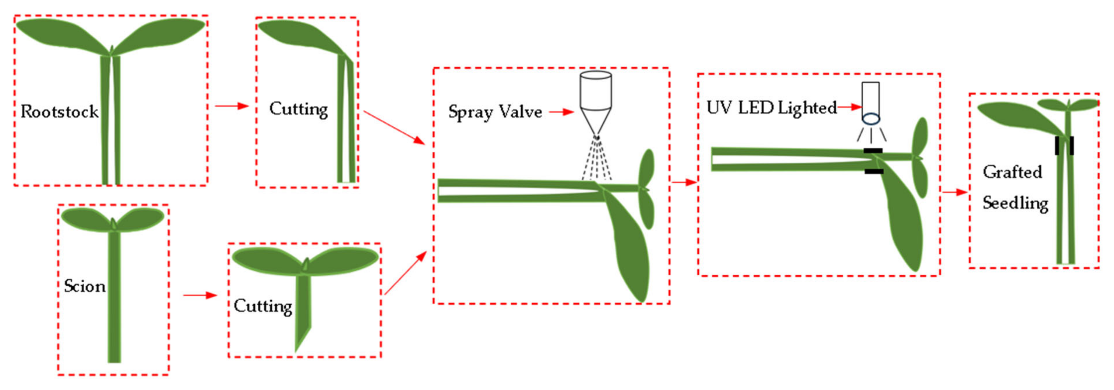
2.1. Theory, Design, and Modeling of the UV Adhesive

2.1.1. Grafting Theory

Splice grafting generally uses plastic clips to fix the rootstock and scion seedlings, as shown in Figure 1a. A certain impact force is exerted on the grafted seedling at the moment of the plastic clamp’s closure, and the clamping force of the plastic clamp is constant during the healing period, which leads to a lack of flexible treatment methods for the fixation of the grafting seedlings. UV adhesive grafting refers to the use of spray valves to atomize the adhesive, sprayed onto the periphery of the rootstock and scion incision butt joints, under UV light source irradiation, triggering the adhesive to quickly solidify to form a thin adhesive film coating, instead of plastic clips to complete the fixation of the grafted seedling, in the red circle as shown in Figure 1b. The comparison found that with UV adhesive grafting of a lightweight parcel layer, the formation of the parcel force is more flexible than that of a plastic clip. The parcel layer has the characteristics of automatic shedding. The UV adhesive spraying process necessitates precise control over parameters such as the atomization pressure, glue supply pressure, and spraying height. Establishing a nozzle model for numerical simulation of the adhesive atomization process is imperative, aiming to ascertain the optimal parameters for grafting through spraying.
The UV adhesive used in grafting should be green and harmless to ensure the safety of the operators and seedlings. LOCTITE AA 3321 (Henkel, Düsseldorf, Germany, 40589) was selected as a medium-viscosity transparent liquid with a density of 1.08 × 10³ kg/m3 and a viscosity of 5.5 kg/(m·s); its dyne value was measured to be 34 using a dyne pen, which means that the surface tension was 0.034 N/m, and its chemical composition is polyurethane acrylate (PUA). The cured wrapping layer has a high resistance to abrasion, adhesion, flexibility, etc. and passed the ISO-10993 biocompatibility test to reach a medical grade [29]. Due to the limited space for grafting operations, the NordsonEFD 781mini spray valve was selected, with a nozzle aperture of 0.01 in, which is a low-flow, low-pressure spray valve, as shown in Figure A1. In a small space, to achieve micro-precision spraying, a working frequency of up to 400 times/min was used, suitable for high-frequency cyclical work scenarios. Spray valve work requires access to a 3-way air source (glue supply pressure, driving pressure, atomization pressure), driving pressure to force the liquid into the nozzle. Under the joint action of the glue supply pressure and atomization pressure, inside the nozzle, we see the formation of a pressure drop so that the liquid atomizes into tiny droplets.
The control circuit for the spray valve is shown in Figure 2. First of all, the gas is compressed using a pressure-regulating filter (pressure range of 0~1.0 Mpa). The pressure-regulating filter is divided into three gas paths: the first for the spray valve for the glue pressure inlet, with pressure gauge 1 to regulate the amount of spray (pressure range of 0.15~0.25 Mpa); the second for the spray valve drive pressure inlet, with solenoid valve 1 to move the spray valve needle up and down (pressure range of 0.4~0.5 Mpa); and the third for the spray valve atomization pressure inlet, with solenoid valve 2 to control the intervention of atomized gas (pressure range of 0.20~0.30 Mpa). Solenoid valve 1 and solenoid valve 2 are controlled using the controller.
The ValveMate 8040 controller is shown in Figure A2. It includes a programmable dispensing time, a digital display for time reading, and four independent solenoid valve drives and can communicate inputs and outputs with the host PLC, with microprocessor circuitry for precise spray control. The external solenoid provides low-volume, low-pressure (LVLP) air to the nozzle by connecting the nozzle air pressure regulator for a high transfer efficiency and does not result in over-spraying. In addition, it has the characteristics of high-frequency cycle control, so it can adjust the time of a single working cycle with an accuracy of 0.001 s. When the work cycle ends, the air in the nozzle continues for a few milliseconds to ensure a clean, clog-free cut-off, and then the controller signals that the process is complete.
The UV adhesive curing speed is affected by the light intensity, spectral distribution, irradiation time, substrate light transmission, and other factors. The spray valve is a micro-spray. The point light source curing machine model is HY-UV0003UV (Zhuhai Hao Yun Optoelectronics Technology Co., Ltd., No. 222, Cuizian North Third Street, Zhuhai, Guangdong, China), as shown in Figure A3. Through the conversion of electro-optical energy, the LED high-power ultraviolet diode chip produces high-purity 365 nm monochromatic ultraviolet light at an irradiation distance of 10 mm and with a light intensity of 6000 MW/cm2. We estimated using a preliminary test that the adhesive dose of a single grafted seedling was about 0.01 g, and the weight of a single plastic clip is about 1 g. Watermelon grafting requires a lower dosage of UV adhesive, forming an adhesive film around the grafted seedling with a thickness of 0.1 mm to 0.3 mm, and rapid curing is accomplished within a few seconds. Grafted seedlings are sprayed as shown in Figure 3. The cross-section of the seedling stem was approximately elliptical, and the UV adhesive was sprayed from the spray valve in the form of a solid cone, downward and perpendicular to the long axis of the seedling incision at the butt joint.
The coverage area of the seedling spraying depends on the spray cone angle and spray height; the larger the spray cone angle and spray height, the larger the film-forming area, forming a semi-encapsulated adhesive film on the outside of the grafted seedling’s incision butt joints, an ellipsoidal film with a thickness of 0.1 mm to 0.3 mm. The shaded portion is the film-forming range of the adhesive under the conditions of different spraying parameters, as shown in Figure 4.
The spray valve’s spraying flow rate function is recorded as f , indicating the spray valve, the unit of time, and the stereo angle of the liquid volume sprayed, that is
f = d V d Ω d t
The cumulative rate of the spray thickness d S at any point S on the sprayed surface in the conical spraying area is:
d S = f · cos γ r 2
The three-dimensional spatial distribution of the spray is shown in Figure 5. γ is the angle between the unit vector and the XOY plane from point P of the nozzle outlet to point S of the spray surface, and r is the length of PS.
The cutting angle is 30° (rootstock on the left, scion on the right), b 1 and b 2 are the short-axis dimensions of the rootstock and scion stems, respectively, and the adhesive film-forming length needs to be greater than L if the sprayed adhesive is to completely encapsulate the cut, as shown in Figure 6.
The film-forming length is:
L = b 2 tan 30 °

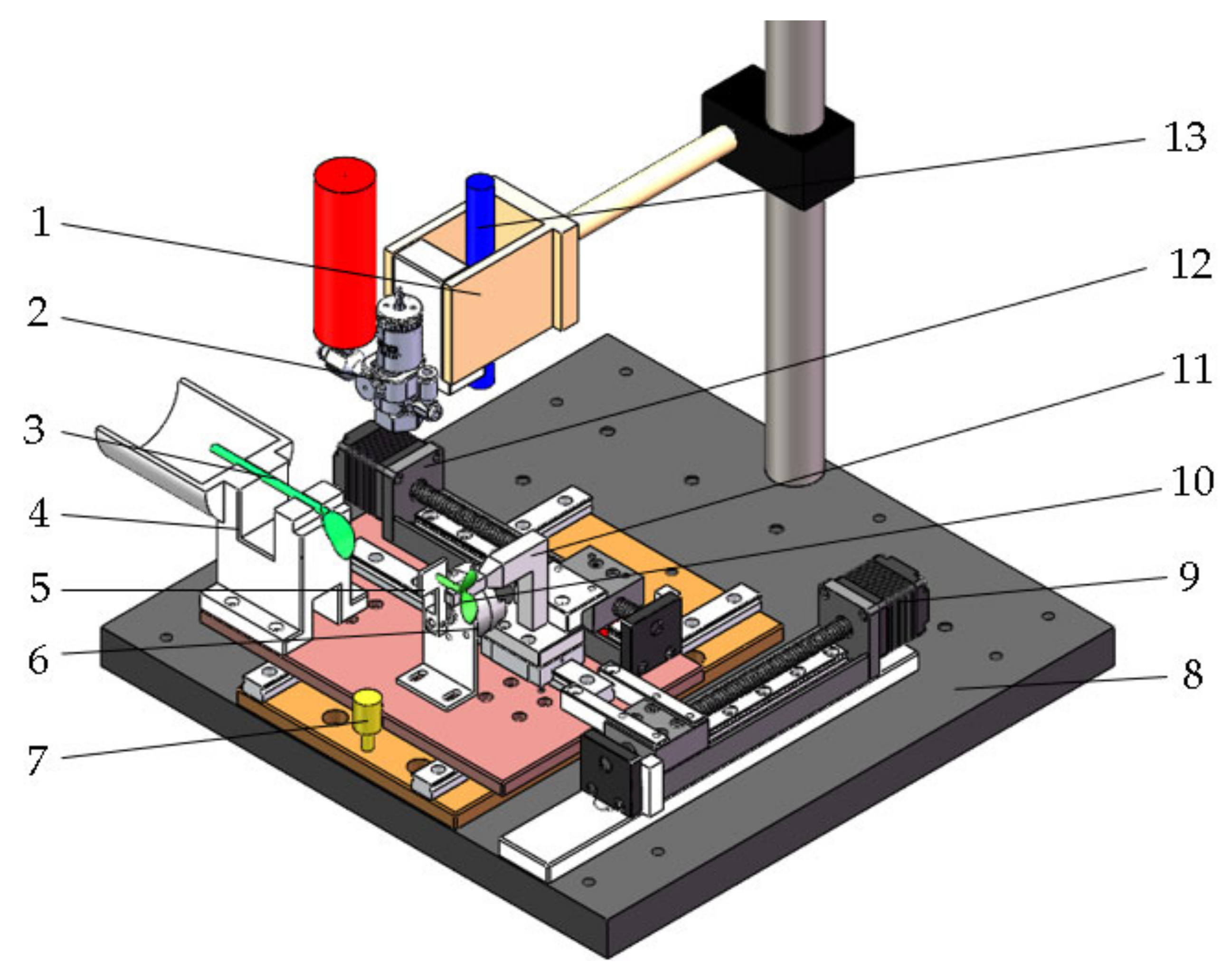
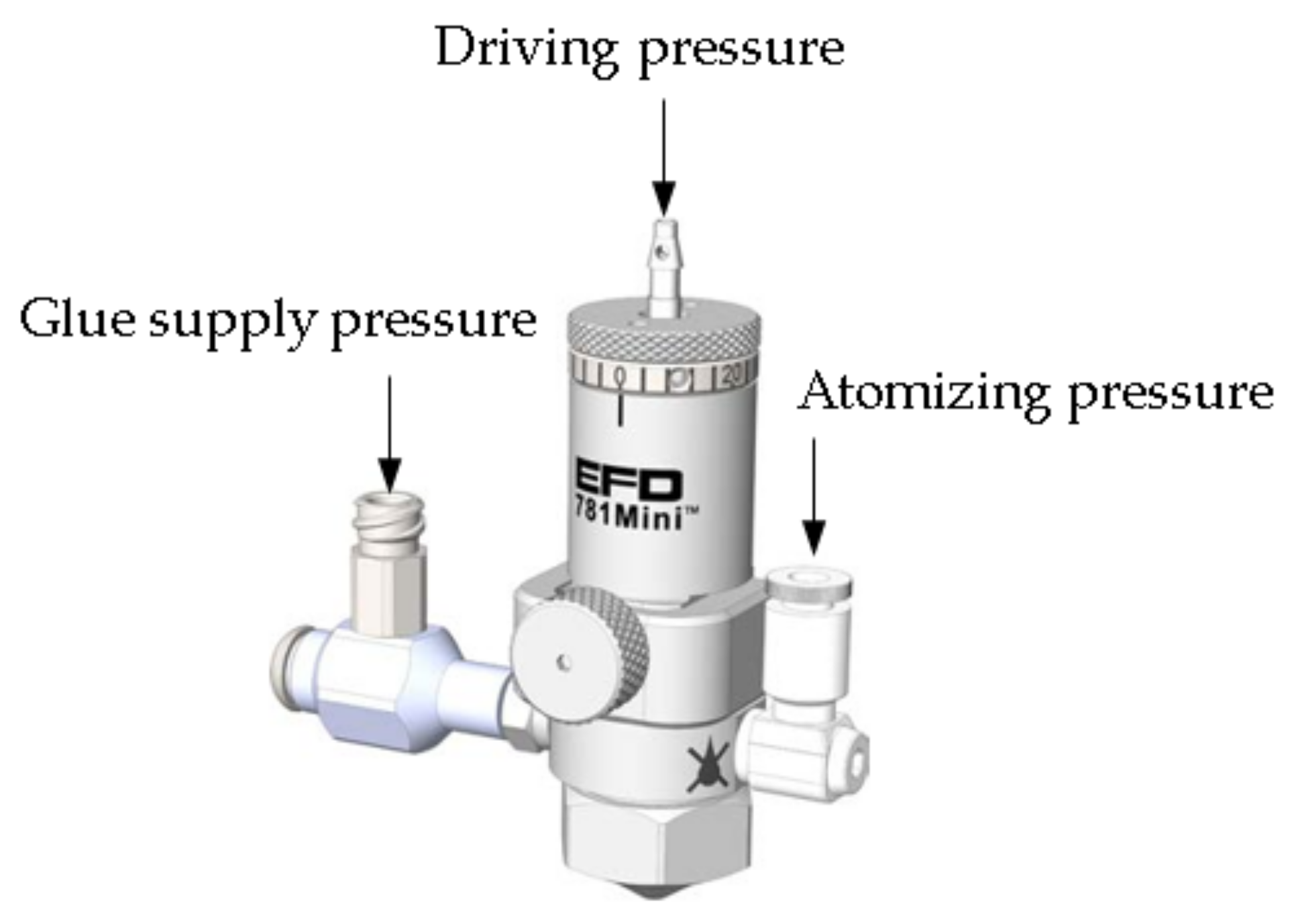
2.1.2. Grafting Device Design
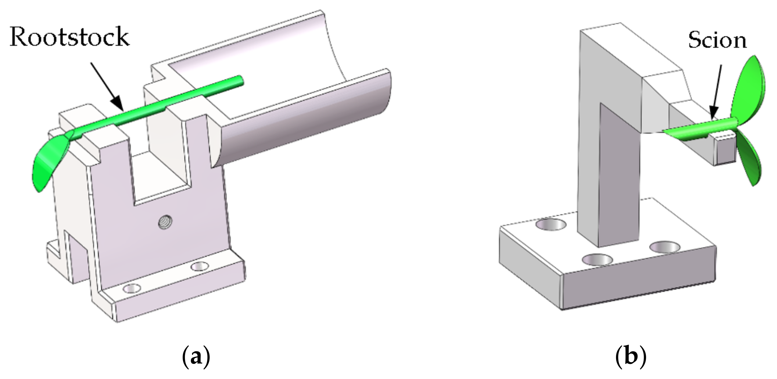
The grafting device consists of a spray valve, a rootstock adsorption mechanism, a scion positioning plate, a rotary cylinder, a sliding plate, a frame, a Y-axis linear slide, a scion adsorption mechanism, an X-axis linear slide, a UV curing lamp, etc., as shown in Figure 7. It is divided into 5 processes, namely the seedling supply, butt joining, spraying, curing, and seedling dismounting.
The installation layout is as follows:
① The spray valve (2) and UV curing lamp (13) in the vertical direction are fixed and mounted onto fixture (1), with fixture (1) through the column mounted onto frame (8);
② The rootstock adsorption mechanism (4), rotary cylinder (6), and X-axis linear slide (12) are installed on the sliding plate (7). The sliding plate (7) is installed on the frame (8) using a linear slide block;
③ The scion adsorption mechanism (11) is mounted onto the X-axis linear slide (12), and the X-axis linear slide (12) drives the scion adsorption mechanism (11) to complete the incision butt joint movement for the rootstock seedling;
④ The rootstock adsorption mechanism (4), the rotary cylinder (6), and the scion adsorption mechanism (11) are arranged from left to right, and the centers of the adsorption grooves of the rootstock adsorption mechanism (4) and the scion adsorption mechanism (11) are coaxial, which facilitates the realization of accurate butt joining of the scion seedling incision;
⑤ The scion positioning plate (5) is mounted onto the rotary cylinder (6), used for the scion on the seedling limit;
⑥ The Y-axis linear slide (9) is also installed on frame (8); the Y-axis linear slide (9) and sliding plate (7) are connected and fixed, for the rootstock and scion, and transported to the spray valve (2) and UV curing lamp (13) below, respectively, for glue spraying and curing operations.
The principle of spray grafting is shown in Figure 8. The working process is as follows:
① Supplying: The cutting of the rootstock seedling is placed horizontally upward in the adsorption slot of the rootstock adsorption mechanism, the foot switch is stepped on once, and the adsorption slot generates negative pressure adsorption and fixes the stem of the rootstock seedling; the cutting of the scion seedling is placed horizontally and downward into the adsorption slot of the scion adsorption mechanism, and the location of the scion on the seedling is determined using the scion locating plate as the reference. The foot switch is stepped on twice, and the adsorption slot generates negative pressure adsorption and fixes the stem of the scion seedling;
② Butt joining: The scion positioning plate is rotated counterclockwise 90° to a horizontal state, and the scion seedlings on the X-axis linear slide are driven to move to the butt joint position so that the scion seedling incision and rootstock seedling incision fit each other;
③ Spraying: The rootstock and scion seedlings move under the drive of the Y-axis linear slide to the underside of the spray valve, which atomizes the UV adhesive and sprays it out to spray the periphery of the scion incision fitting section;
④ Curing: The rootstock seedlings and scion seedlings continue to move under the drive of the Y-axis linear slide underneath the UV curing lamp, and the UV curing lamp irradiates the UV adhesive sprayed onto the grafted seedlings to cure them rapidly;
⑤ Dismounting: The Y-axis linear slide is reset, the grafted seedling is carried to the butt joint station, the foot switch is stepped on 3 times, the negative pressure air source of the rootstock and scion adsorption mechanism is disconnected, the grafted seedling is manually taken out, and the other mechanisms are reset in turn.
A.
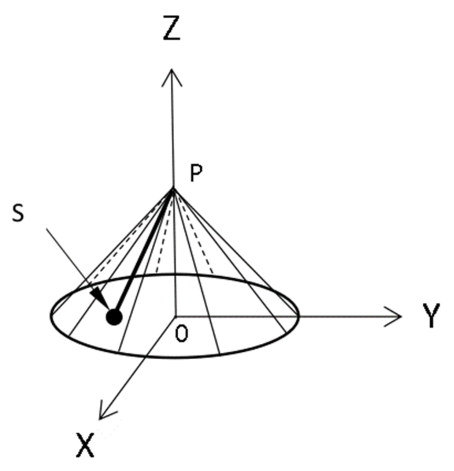
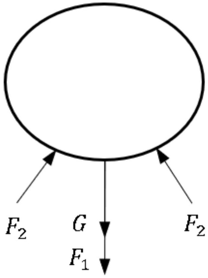
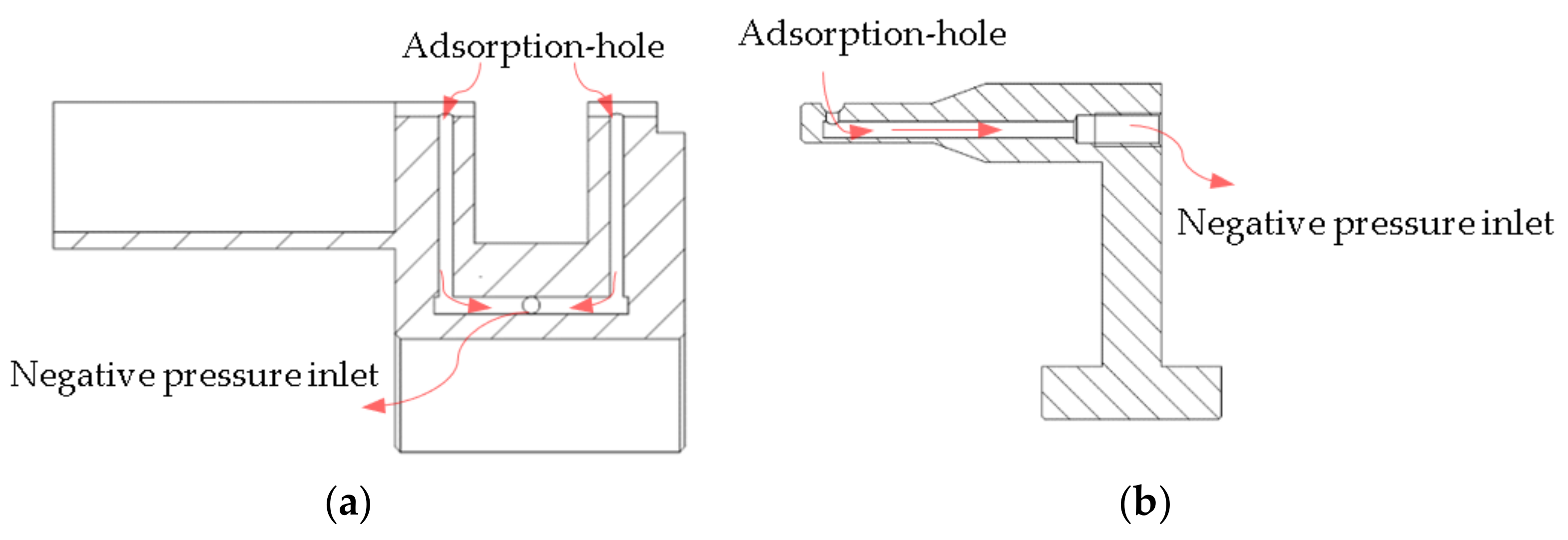
Seedlings Adsorption Mechanism
Most of the grafting machines use the clamping method to position the seedlings, and EVA cushioning material is pasted inside the clamping hand to realize flexible clamping. Due to the differences in the stems of the seedlings, if the strength of the clamping method is not adjustable, the clamping force is not enough for smaller seedlings, resulting in unstable clamping, and the clamping force is too large for larger seedlings, thus damaging the seedlings [30]. The negative pressure adsorption method can be applied to seedlings of different sizes to meet positioning stability and safety.
Adhesive spraying requires the spray valve to be installed in the vertical direction; therefore, the horizontal direction is selected for seedling placement, adsorption, and positioning, and the seedlings adsorption mechanism is equipped with a positioning groove and adsorption holes in the groove. To determine the structural dimensions of the seedlings adsorption mechanism, it is necessary to measure the external characteristic parameters of the seedling. The rootstock and scion selected were Jingxin rootstock No. 2 of white-seeded pumpkin and Jingxin No. 4 of watermelon, respectively, and both the rootstock and scion seedling stems were oval, defining the seedling stems in the direction of the cotyledon unfolding as the short axes and the seedling stems in the perpendicular direction to the short axis as the long axes. The rootstock plant height H was measured, as shown in Figure 9a, as were the seedling stem long axis a 1 and short axis b 1 , as shown in Figure 9b; the length of the hypocotyl after scion cutting was 10 mm to 15 mm, so the plant height of the scions did not need to be measured, only the seedling stems long axis a 2 and short axis b 2 .
The external morphological characteristics of the white-seeded pumpkins and watermelons were measured after 7 days and 10 days of planting, respectively. The sample size was 50 plants each, and the results are shown in Table 1. For the seedlings to be placed smoothly in the positioning groove, the width of the groove should be slightly larger than the size of the long axis of the seedling stems, the depth of the groove should be 3/4 of the size of the short axis of the seedling stems, and the length of the groove should be smaller than the height of the plant.
According to Table 1, the width, depth, and length of the locating groove for the rootstock adsorption mechanism are set to 4.5 mm, 2.5 mm, and 40 mm, respectively, as shown in Figure 10a. Additionally, the rootstock adsorption mechanism is equipped with a soil lump support, making it suitable for both rooted and rootless grafting of rootstocks. The locating groove dimensions for the scion adsorption mechanism are set at 3.5 mm, 1.5 mm, and 5 mm, as depicted in Figure 10b.
The negative pressure inlet of the rootstock adsorption mechanism is located in the lower part, and there are two adsorption holes in the positioning slot, as shown in Figure 11a; the negative pressure inlet of the scion adsorption mechanism is located in the rear part, and there is one adsorption hole in the positioning slot, as shown in Figure 11b. The arrow direction is the direction of the airflow, and the seedlings are adsorbed and fixed into the positioning slot due to the pressure difference.
The force for the adsorption and positioning of the seedlings is shown in Figure 12 (along the stem direction of seedlings). The larger the adsorption force, the better the adsorption performance, provided that the adsorption is stable and the seedlings are not damaged [31].
The equilibrium equation for the adsorption forces on the seedlings is as follows:
F 1 + G F 2 = 0
To ensure that seedlings are not destroyed by excessive adsorption,
F 1 < F σ
F σ = P σ S
S = π d 2 4
In the formula, S is the cross-sectional area of the adsorption hole (mm2); F 1 is the adsorption force (N); F σ is the seedling stem’s breaking pressure (N); P σ is the seedling diameter breaking pressure (Pa); d is the adsorption hole diameter (mm).
In terms of the adsorption size:
F 1 = π ρ C d d 2 v 2 8
In the equation, C d represents the drag coefficient, set to 1.0; ρ is the air density, taken as 1.29 k g / m 3 ; v represents the average velocity of the force equilibrium airflow field.
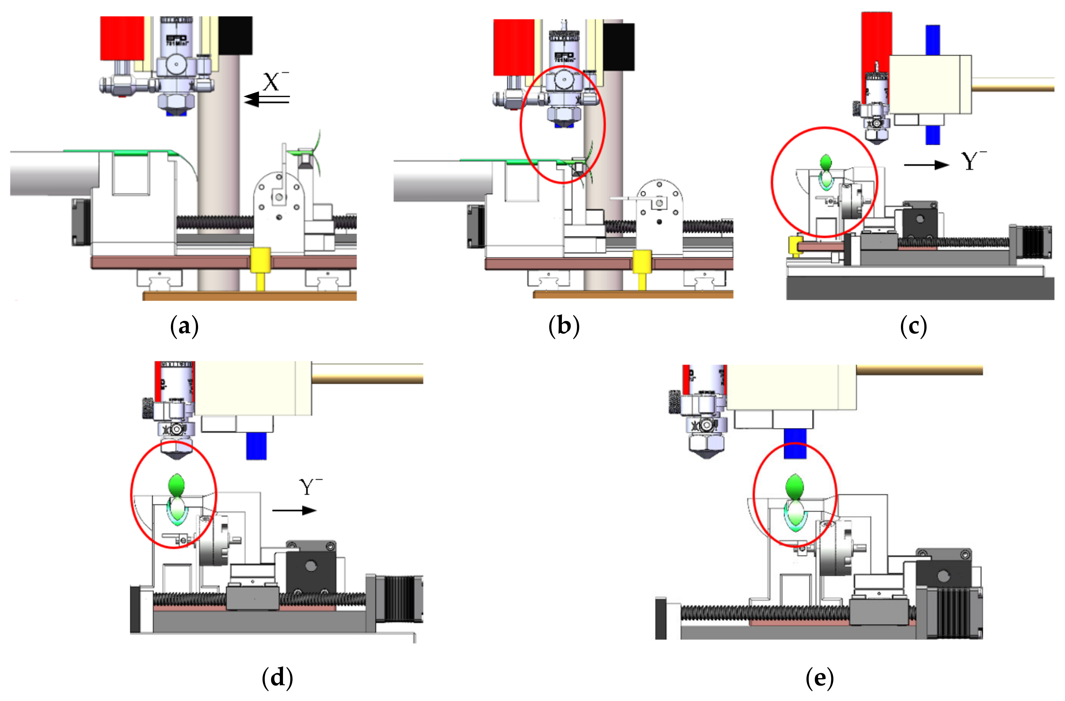
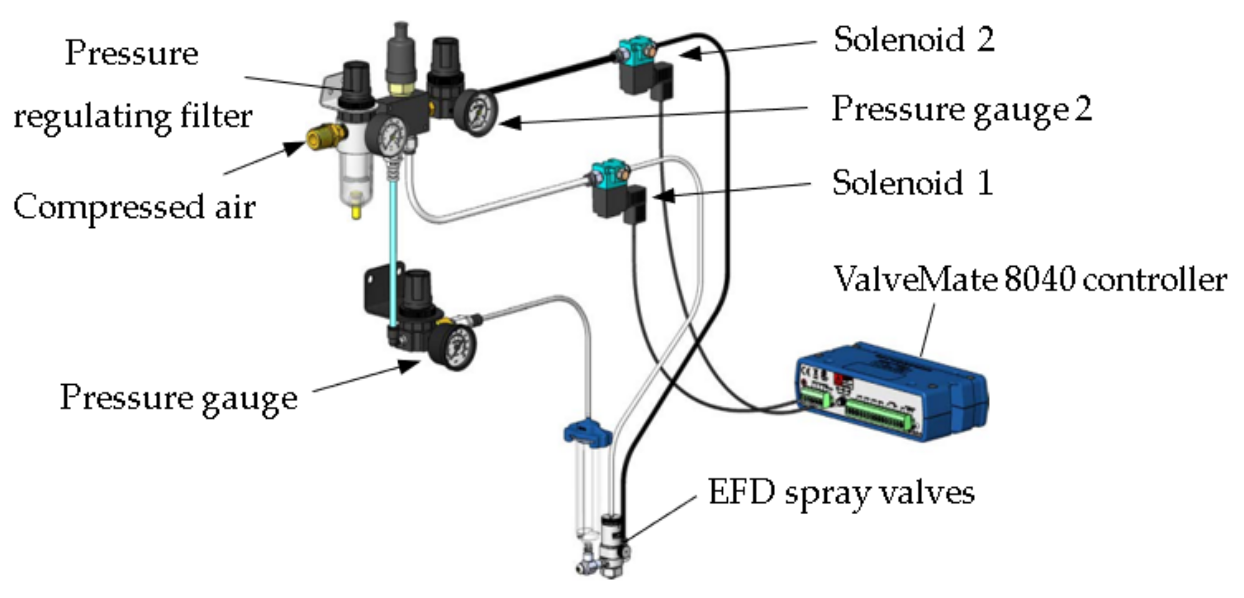
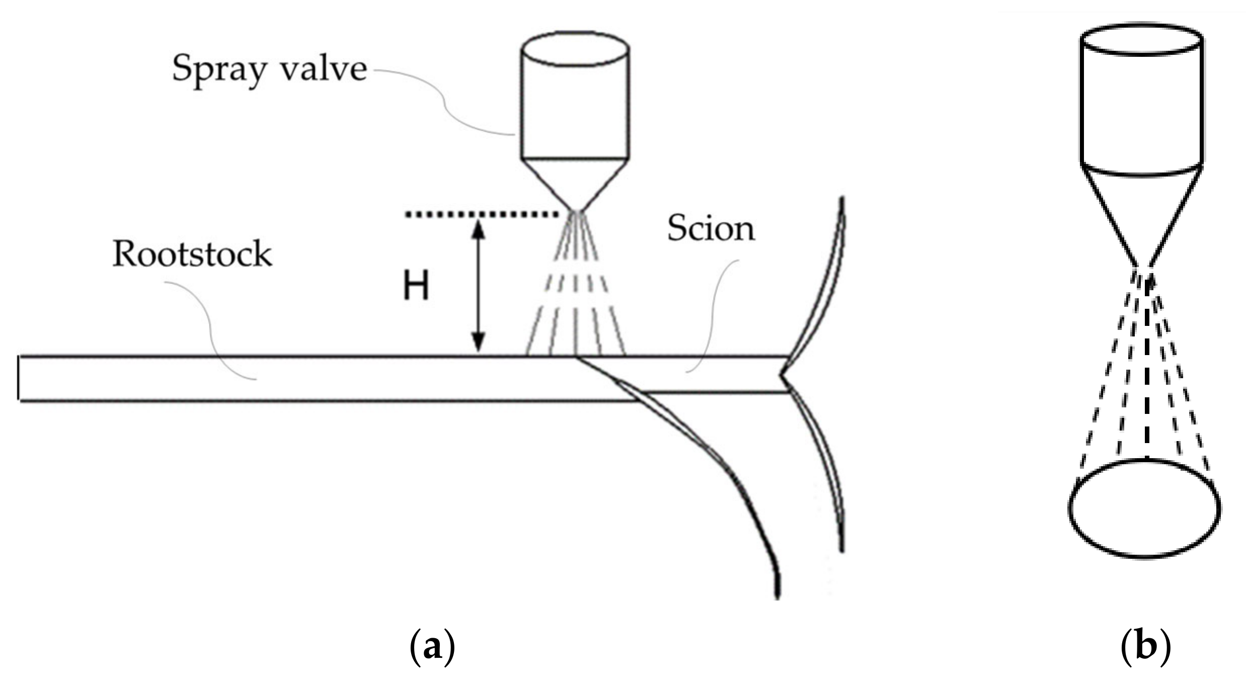
  • B. Butt Joining and Handling Mechanisms
The butt joint and handling of the rootstock and scion seedlings are completed under the drive of the X- and Y-axis linear slides; the linear slides have a lead of 12 mm, an effective stroke of 100 mm, and a maximum moving speed of 0.1 m/s. A butt joint and handling diagram is shown in Figure 13, and the processes are as follows:
① Completing the adsorption positioning of the rootstock and scion seedlings using the adsorption mechanism and scion positioning plate.
② The X-axis linear sliding table drives the scion to move 50 mm in the X negative direction to complete the butt joint.
③ The Y-axis stepper slide drives the handling mechanism to the spraying and curing stations.
④ The Y-axis linear slide drives the rootstock and scion seedling as a whole to move 50 mm in the negative direction of the Y-axis to the spraying station; the spraying height is 5 mm to 15 mm.
⑤ After the spraying is completed by the spraying valve, it will continue to move 42 mm in the negative direction of the Y-axis to reach the curing station. The UV curing lamp works for 1~2 S.
Finally, each mechanism is reset in turn.

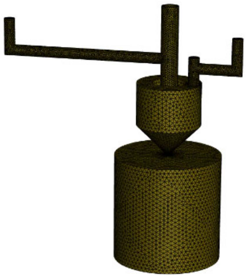
2.1.3. Simulation Modeling

① Adsorption Modeling
To determine the optimum parameters for the adsorption mechanism, hydrodynamic simulation analysis is carried out for different pore diameters and numbers of pores. For the calculation, the fluid inside the air chamber is considered a continuous phase, and the air fluid is considered an incompressible viscous fluid in the negative pressure adsorption process, which must follow the laws of the conservation of mass, momentum, and energy [32], with the Navier–Stokes equation satisfying these conditions being:
ρ t + x i ρ u i = 0
To keep the set of equations closed, the fluid inside the gas chamber of the adsorption mechanism was numerically simulated using the standard k ε turbulence model, viz:
t ρ k + x i ρ k u i = x j μ + μ t σ k + k x j + G k + G b ρ ε Y M + S k
t ρ ε + x i ρ ε u i = x j μ + μ t σ ε ε x j + C 1 ε ε k G k + C 3 ε G b C 2 ε ρ ε 2 k + S ε
Among this,
μ t = ρ C μ k 2 ε
G k = μ t μ i x i + μ j x i μ i x i
G b = β g i μ t P r T x i
Y M = 2 ρ ε M a 2
where G k is the production term for the turbulent kinetic energy k due to the mean velocity gradient; G b is the generation term for the turbulent kinetic energy k from buoyancy; μ t is the turbulent viscosity; β is the thermal expansion coefficient; Y M is the contribution of pulsation expansion in compressible turbulence; P r is the turbulent Prandtl number; ε is the dissipation rate; M a is the Mach number; S k , S ε are source terms; the empirical constants C 1 ε , C 2 ε , C 3 ε are taken as 1.44, 1.92, and 1.0, respectively, and σ ε is set to 1.2.
The size of the diameter of the adsorption hole in the positioning groove affects the contact area between the airflow and the seedlings. The maximum hole diameter should be smaller than the size of the long axis of the seedlings, and the hole diameter should not be too small; otherwise, it will make the airflow and the contact area of the seedlings too small and thus lead to adsorption instability. Three sizes of 1.5 mm, 2.0 mm, and 2.5 mm were selected as the pore size variables. The number of adsorption holes affects the force points of the seedlings. The more adsorption holes there are, the more points of force the seedlings are subject to, so the seedlings become more stable, but because of the dispersion of forces, the adsorption force is smaller. Conversely, with fewer adsorption holes, the adhesion force of the seedlings is greater but less stable. The selected number of adsorption holes is 1 to 3 in this research.
The standard k ε turbulence model is selected, the inlet boundary condition is the pressure inlet, the pressure magnitude is −40 kPa, the outlet boundary condition is standard atmospheric pressure, the wall is set as a no-slip wall boundary condition, and the adsorption hole size is small, so it is necessary to take into account the influence of the boundary layer, using the standard wall functions to this end [33].
② Spraying Modeling
Firstly, the fluid domain model of the spray valve is established using SolidWorks 2022 3D software, and the model is meshed using Fluent Meshing. Due to the large change in the velocity gradient at the nozzle exit, the mesh encryption process is carried out at the nozzle exit, and the mesh type is a tetrahedral mesh, with a total number of meshes of 939,340 and a minimum orthogonal mass of 0.46, as shown in Figure A4. The flow field distribution of the gas–liquid two-phase flow in the nozzle is simulated using the VOF method [34], and the liquid-phase velocity, diffusion angle, and mass flow rate at the nozzle outlet are monitored to obtain them and use them as boundary conditions for the DPM injection model [35].
In the VOF model calculations, the realizable k-ε turbulence model was used, with Rosin–Rammler distribution for the droplet size and a diffusion factor of 3.5. The sprayed wall was set as a wall film model, and the rest were set as exit boundary conditions. The pressure–velocity coupled PISO algorithm was used in second-order upwind format.
The spray valve’s spray adhesive mist droplets move in the flow field mainly on the basis of their own gravity and air impact [36]. The droplet force balance equation is:
m d u p d t + F D + G = 0
where
F D = 1 2 C D ρ f A f u u p 2
where F D is the trailing force on the droplet, m is the droplet mass, G is the droplet weight, u p is the droplet velocity, C D is the coefficient of the trailing force, ρ f is the fluid density, A f is the reference area, and u is the fluid velocity.
The droplet–wall impact model can be categorized into four modes: adhesion, rebound, wall-attached jet, and splashing [37,38]. The Weber number can be used as a basis for judging the impact model, and the Weber number is calculated as:
W e = ρ v 2 l σ
where ρ is the fluid density, v is the characteristic flow rate, l is the characteristic length, and σ is the fluid surface tension coefficient.
(1)
When W e < 5, the collision of the droplet with the wall is modeled as adhesion;
(2)
When 5 ≤ W e ≤ 10, the collision between the droplet and the wall is modeled as a rebound;
(3)
When W e > 10, the droplet–wall collision is modeled as a splash/wall-attached jet.
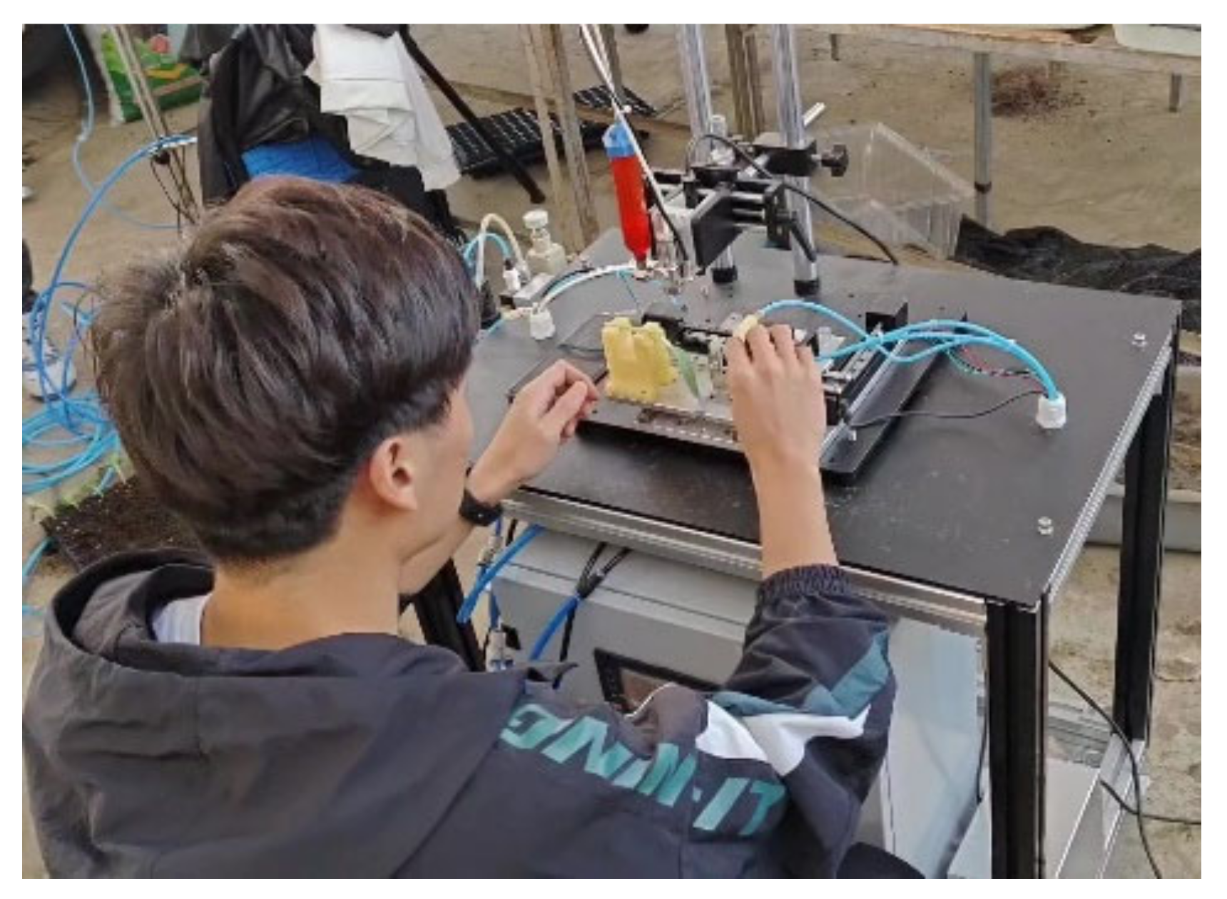
The droplet’s Weber number should not be too large if more droplets are made to adhere to the wall on first collision.
The following equation is used for the conservation of the droplet’s mass:
h t + s · h V ¯ l = m ˙ s ρ l
where ρ l is the density of the liquid film k g / m 3 , h is the thickness of the liquid film m , V ¯ l is the average velocity of the liquid film flow m / s , and m ˙ s is the mass source of the liquid film per unit wall area k g / m 2 · s .
We use the following conservation of momentum equation:
h V ¯ l t + s · h V ¯ l V ¯ l = h s P L ρ l + g ¯ τ h + 3 2 ρ l τ ¯ f s 3 v l h V ¯ l

2.2. Tests

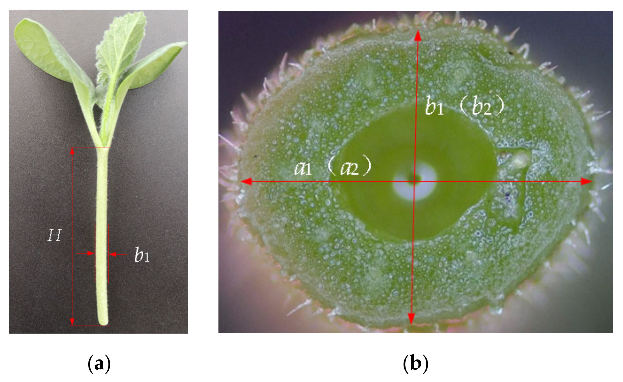
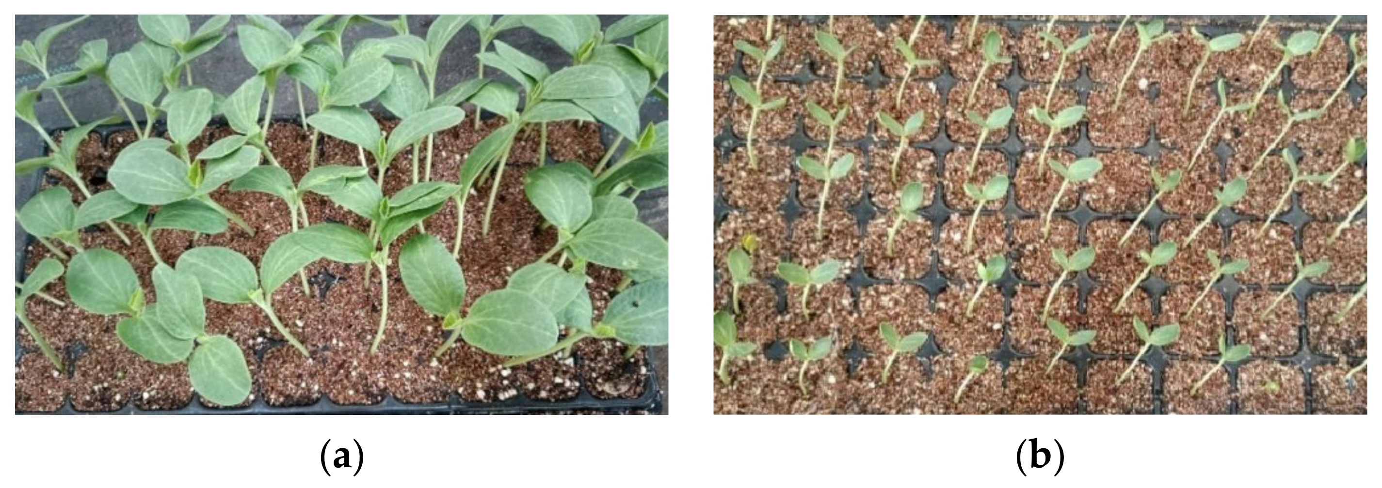
2.2.1. Test Materials

The seedling nursery was located in the solar greenhouse of the Beijing Academy of Agricultural and Forestry Sciences (Haidian District, Beijing, China, 39°56′28″ N, 116°16′53″ E). Jingxin rootstock No. 2, a white-seeded pumpkin variety, was chosen as the rootstock, while Jingxin No. 4, of watermelon, was selected as the scion. The rootstock and scion were sown separately using standard hole trays of 5 × 10 and 6 × 12, respectively. For optimal rootstock grafting, the seedling age was set at 8 to 10 days, with the external morphology of the rootstock characterized by two spreading cotyledons and a stem thickness of about 3.5 mm, as depicted in Figure 14a. In contrast, the scion was sown three days earlier than the rootstock, displaying 2 to 3 leaves in its growth [39,40], as shown in Figure 14b.
The designed spray grafting device was subjected to drawing, machining, module assembly, and control software development to integrate the spray grafting device as shown in Figure A5, which only requires one person to operate it.

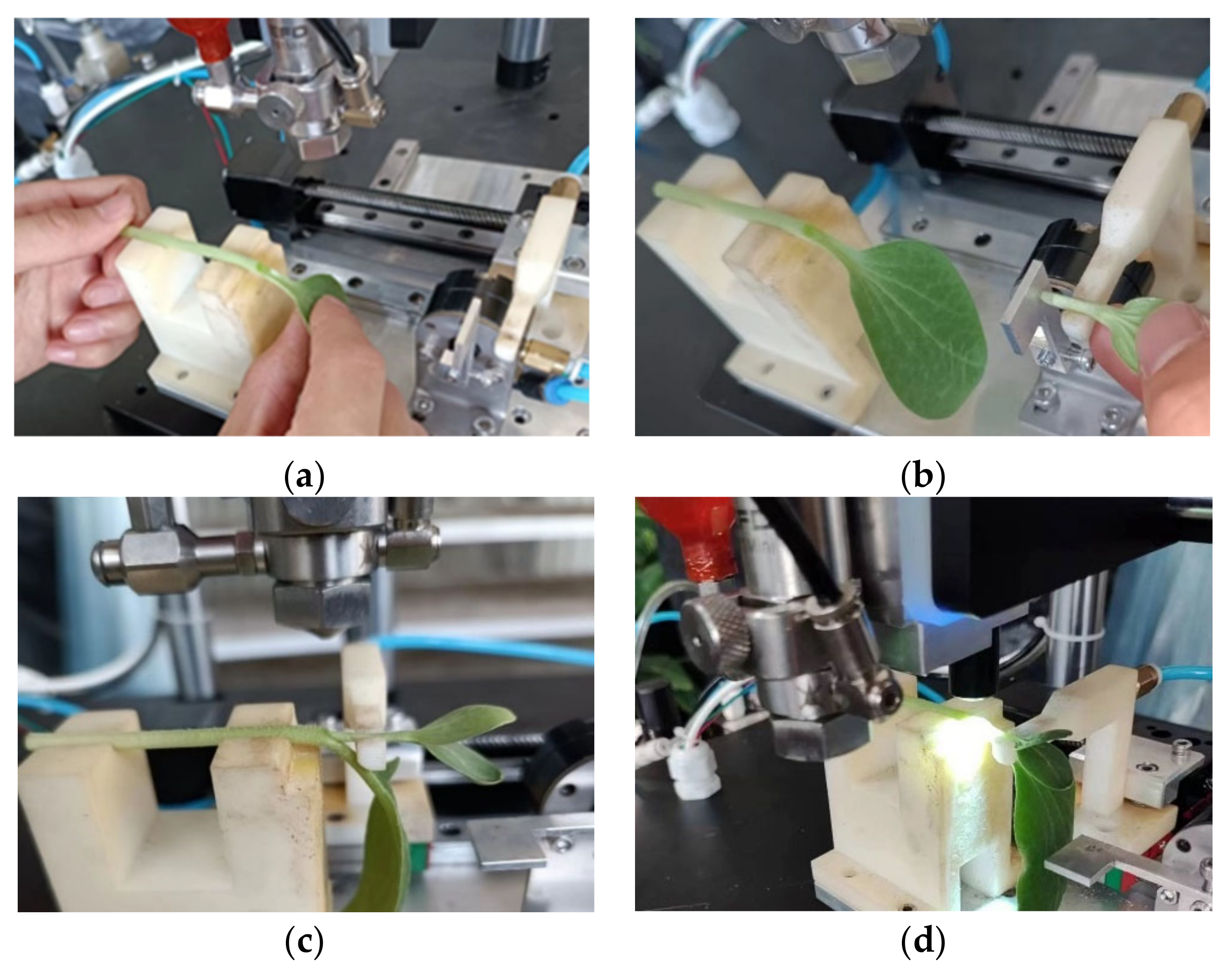
2.2.2. Test Contents and Methods

To determine the optimal grafting process parameters for the spray valve, with atomization pressure, glue supply pressure, and spraying height as the independent variables and grafting success rate as the dependent variable, we analyzed the success rate of watermelon grafting using an orthogonal test, verified the grafting survival rate with the optimal combination of factors, and analyzed the effect of the adhesive film-forming length on the effective spraying rate.
The atomization pressure, glue supply pressure, and spraying height of the spray valve were selected for a 3-factor, 3-level orthogonal experimental design using the L 9 ( 3 3 ) table, and the coding of the factor levels is shown in Table 2. A total of 9 groups of experiments were arranged, and 30 grafted seedlings were completed in each group of experiments.
The grafting process is, sequentially, seedling supply, butt joining, spraying, curing, and seedling dismounting. First, the operator uses a blade to cut the rootstock and scion seedlings at a 30° cutting angle; then, the rootstock and scion seedlings are put into the seedlings adsorption mechanism, respectively, as seen in Figure 15a,b; and then butt joining and spraying, as in Figure 15c, and curing and seedling dismounting are completed automatically, as in Figure 15d.
The test indicators are as follows:
(1)
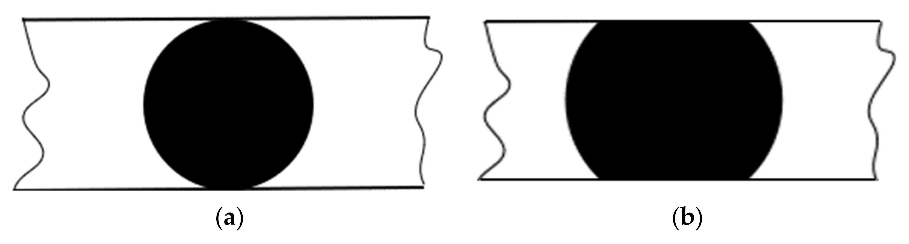
The grafting success rate for each group of tests was counted, and the grafting was considered successful if the cut surfaces of the rootstock and scion were closely adhered to form a single unit after spray grafting. Otherwise, it was regarded as a grafting failure, as shown in Figure A6.
(2)
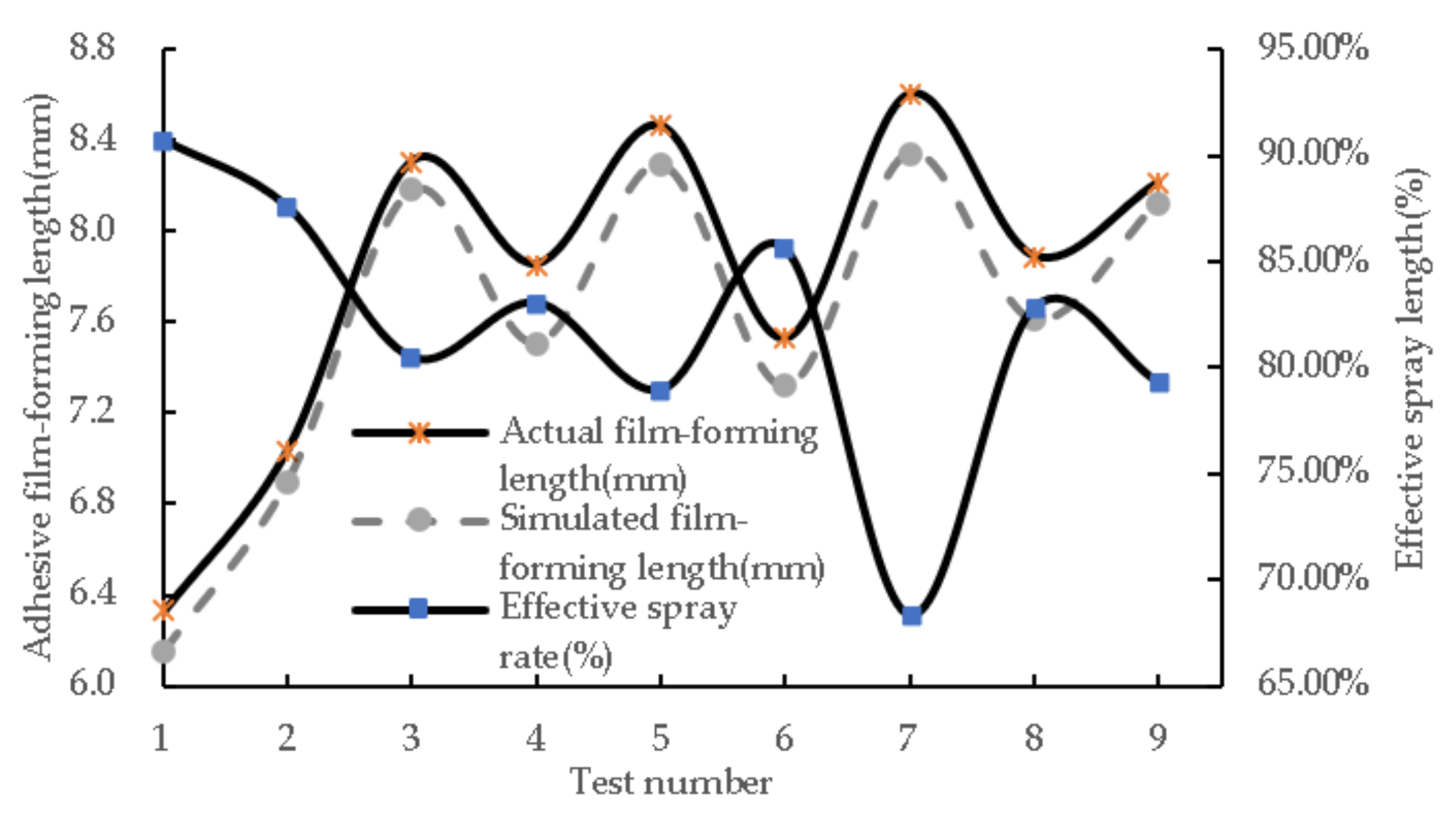
Since the adhesive cannot be completely sprayed onto the grafted seedling, the amount of adhesive sprayed onto the grafted seedling is called the effective spray volume. The mass of the rootstock and scion before spraying, the mass of the adhesive applied in a single spray by the spray valve, and the mass of the grafted seedling after spraying were weighed separately. The formula for calculating the effective spray rate R e s for the adhesive is as follows:
Effective spray rate R e s = M a s s   o f   g r a f t e d   s e e d l i n g s   a f t e r   s p r a y i n g   ( g ) M a s s   o f   r o o t s t o c k   a n d   s c i o n   b e f o r e   s p r a y i n g   ( g ) + M a s s   o f   a d h e s i v e   a p p l i e d   i n   a   s i n g l e   s p r a y   ( g ) × 100 %
(3)
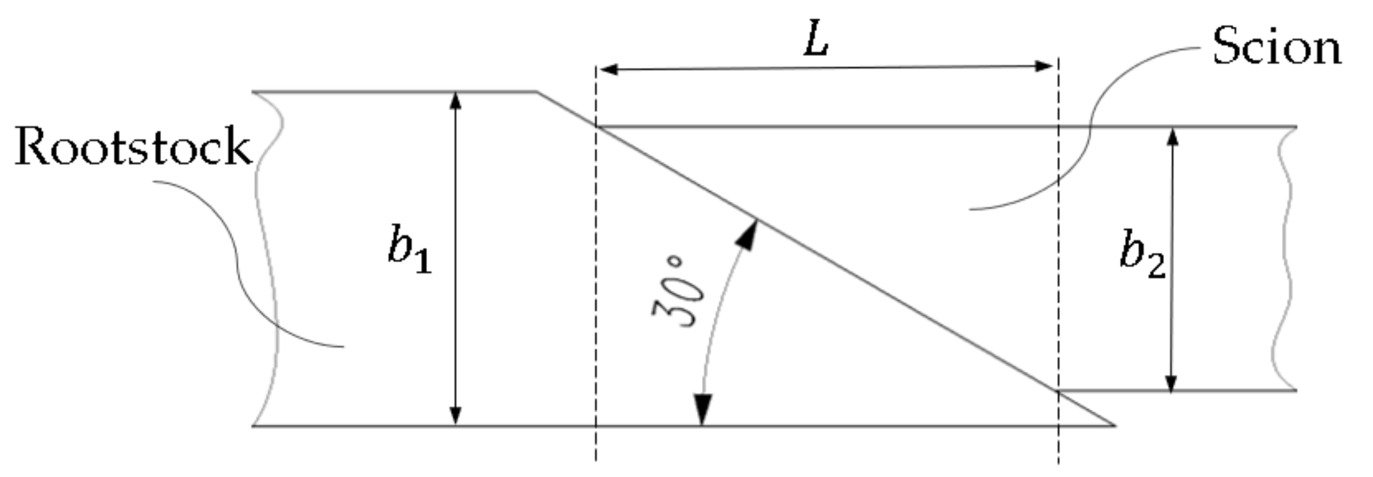
The adhesive film length along the axis of the grafted seedling was measured.
(4)
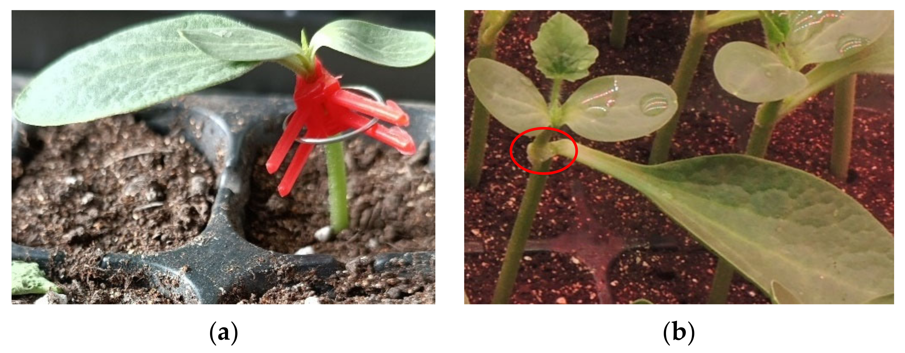
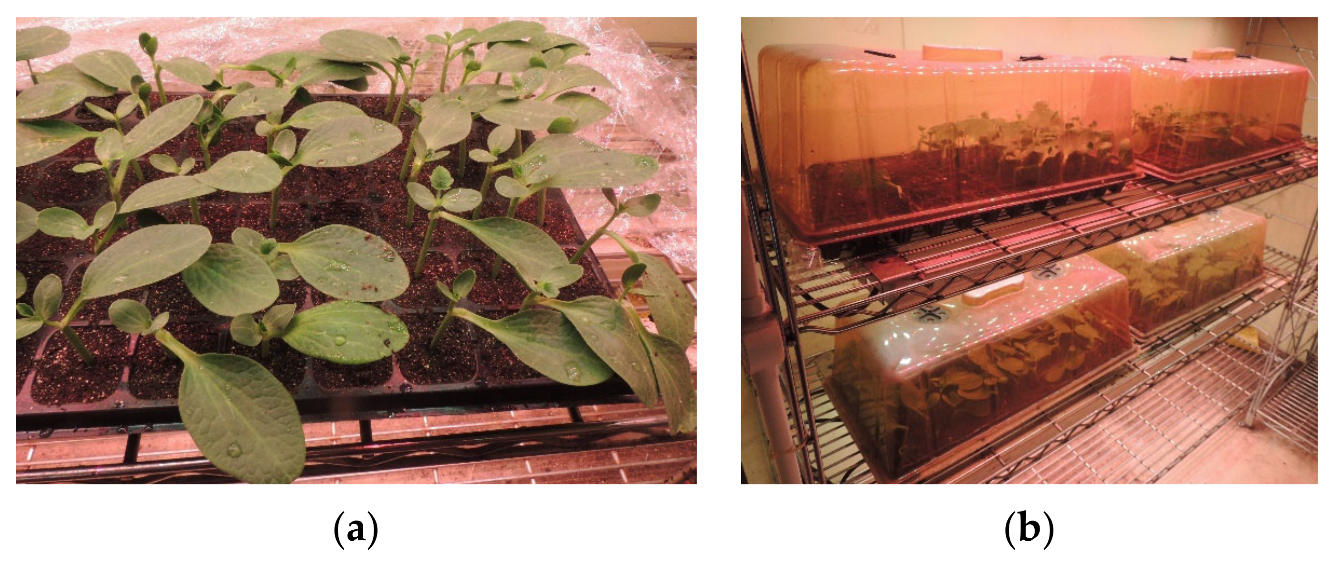
The grafted seedlings were completed under the conditions of the optimal process parameters for adhesive spray grafting 200 plants and put into an incubator for healing treatment. Environmental conditions: 80% to 90% humidity, daytime temperature 28 °C, nighttime temperature 25 °C, healing under these conditions for 7 days [41,42]. If the scions can grow new cotyledons, they will be considered as having survived. Otherwise, they will be not. Then, the grafting survival rate will be counted.

3. Results and Discussion

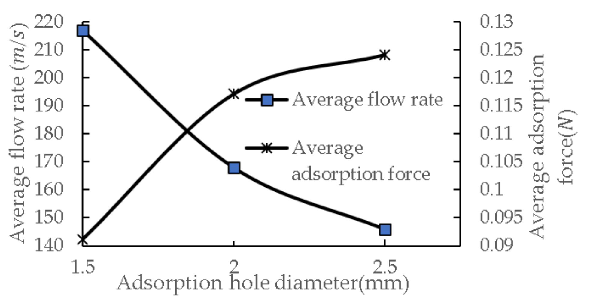
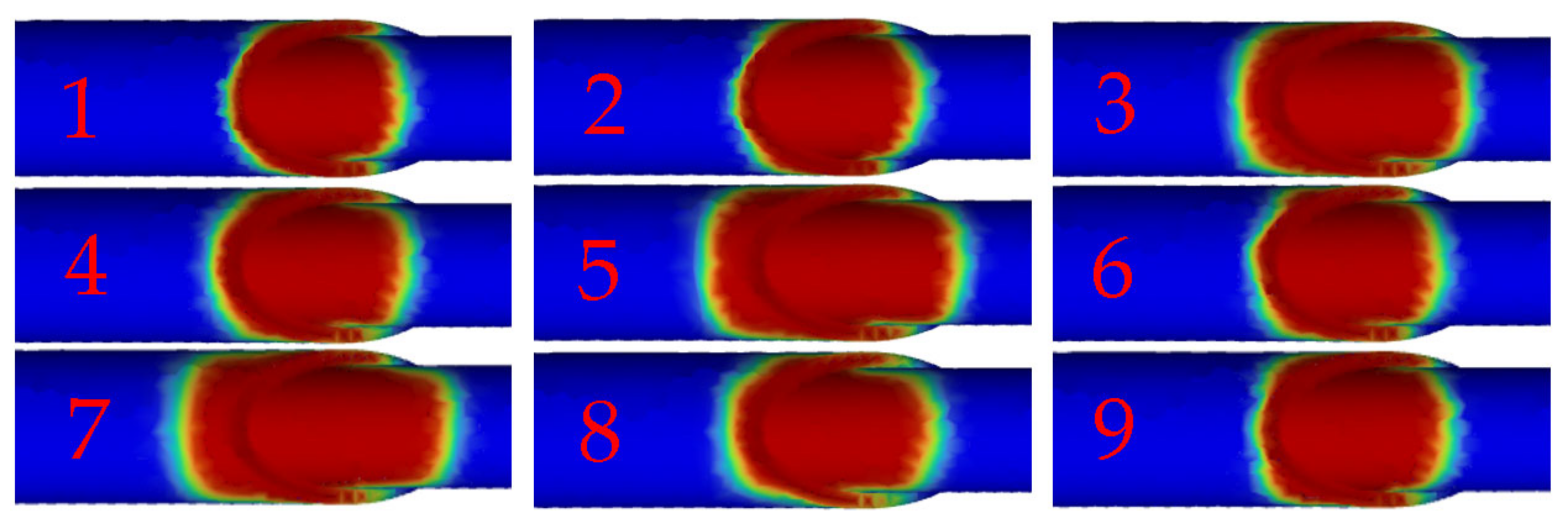
3.1. Simulation Results for the Seedling Adsorption

The effects of the number of suction holes and the number of suction holes on the adsorption properties of the rootstock adsorption mechanism were analyzed using fluid simulation. When the diameter of the adsorption hole is 2 mm, the distribution of the number of adsorption holes in the flow field is shown in Figure A7.
The adsorption force generated by a single adsorption hole acts on the rootstock seedling at the middle of the seedling stem, the average velocity of the airflow is 220 m/s, and the average pressure is −25,646 Pa. Since the rootstock seedling belongs to a non-rigid object, the two ends of the seedling stem may be shifted. Airflow dispersion due to double adsorption holes, the airflow speed is significantly lower than the single adsorption hole speed. The vacuum here compared to single adsorption holes is also reduced, the average speed of the airflow is 168 m/s, and the average pressure is −17,996 Pa. With adsorption holes of the same diameter, the total adsorption force for double adsorption holes is greater than single adsorption holes’ adsorption force. The rootstock has two points of force with two holes, so both from the point of view of the size and force stability of the adsorption force, double adsorption holes are better than single adsorption holes. With three adsorption holes, the gas flow field distribution and the gas flow rate at both ends of the adsorption hole channel are the same, the average velocity of the gas flow at the exit is 97.6 m/s, and the average pressure is −5921 Pa. The gas flow rate for the middle adsorption hole channel is obviously larger than the gas flow rate of the two ends of the channel, the average velocity of the gas flow at the exit is 148.5 m/s, and the average pressure is −15,067 Pa. In the adsorption process for rootstock seedlings, the force between the middle and both ends of the seedling stems was different, and the two ends of the stems might buckle, which does not meet the requirements of stable adsorption. Therefore, the rootstock adsorption mechanism has a good adsorption stability under double adsorption hole conditions.
The effect of different adsorption hole diameters on the average flow rate and adsorption force of the adsorption holes under double adsorption hole conditions is shown in Figure A8. Calculations using Equation (8) show that as the diameter of the adsorption hole increases, the velocity of the airflow at the exit of the adsorption hole decreases gradually, and the total adsorption force increases gradually, which suggests that the effect of the diameter of the adsorption hole on the adsorption force is more significant than the velocity of the airflow, and when the diameter of the adsorption hole is 2.5 mm, the average flow rate of the airflow is 146 m/s, the average pressure is −16,281 Pa, and the magnitude of the adsorption force is 0.124 N, which signifies a good adsorption performance.
In summary, the optimal combination of parameters for the rootstock adsorption mechanism is double adsorption holes and an adsorption hole diameter of 2.5 mm. The length of the seedling stem after scion cutting is 10 mm to 15 mm, and the scion seedling stem is smaller, so the scion adsorption mechanism is designed as a single adsorption hole, and the diameter of the adsorption hole is 2.0 mm.

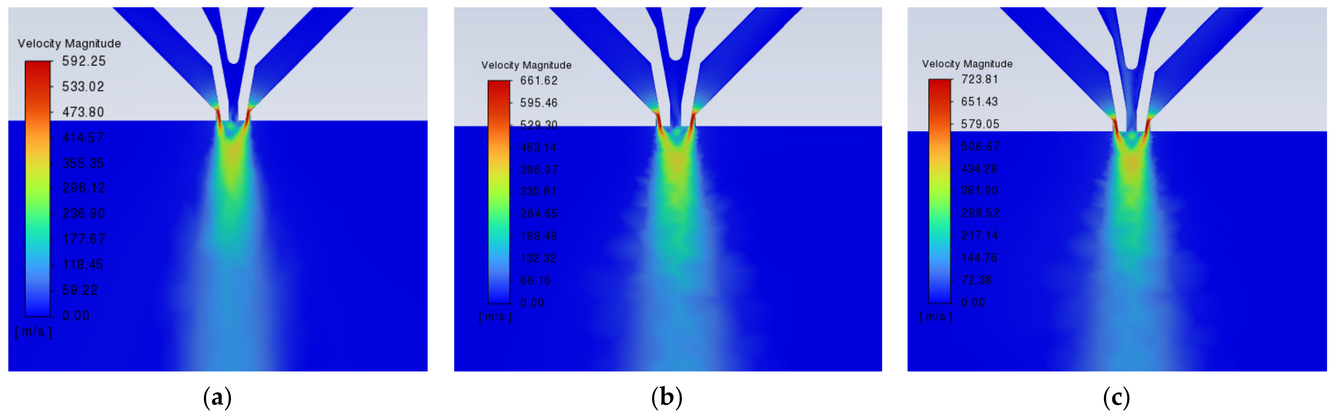
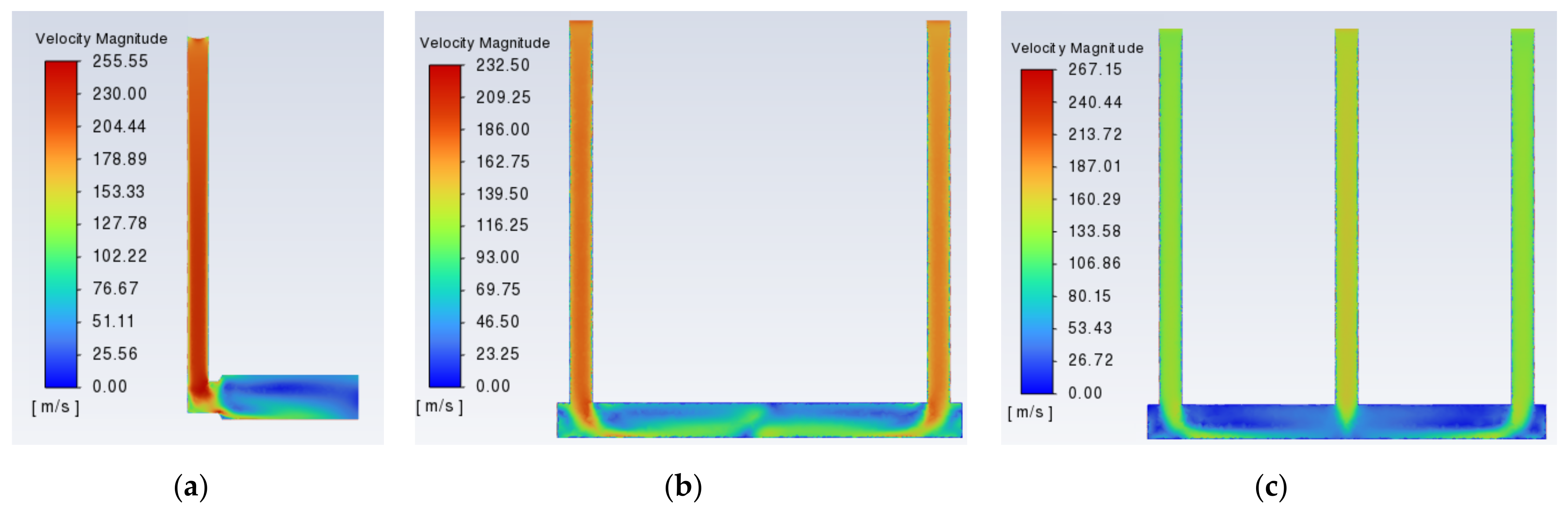
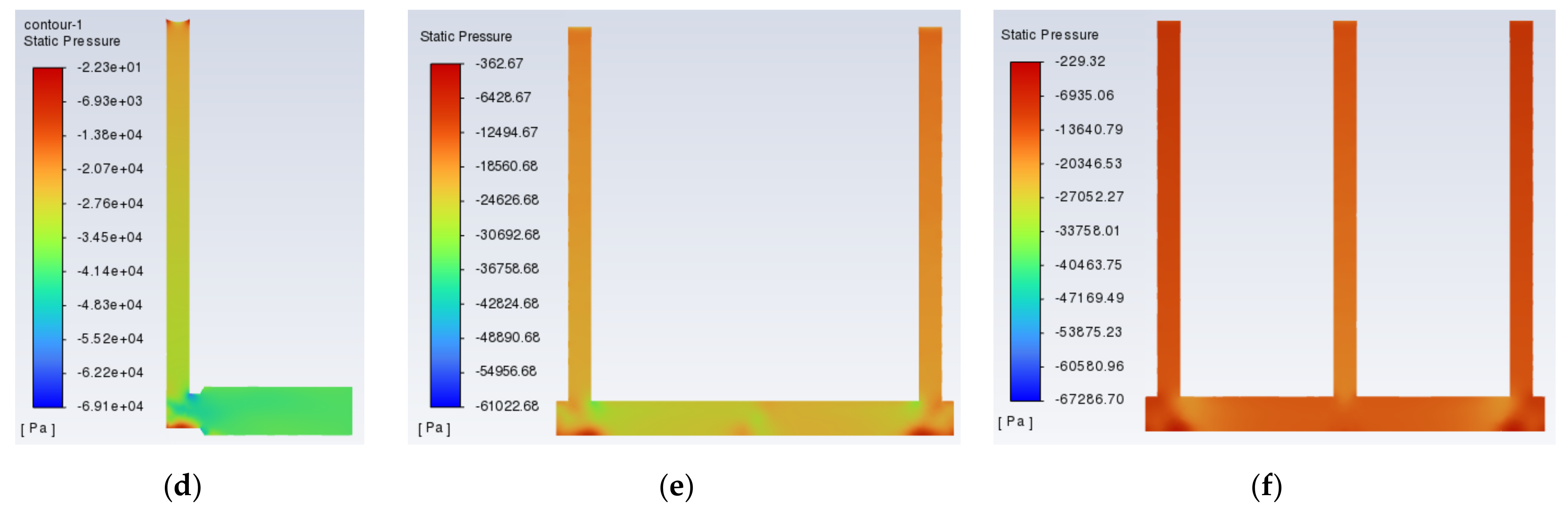
3.2. Spraying Simulation Results

The atomizing pressure of the spray valve determines the spray cone angle, and the glue supply pressure determines the mass flow rate for the adhesive spray. A velocity cloud for the gas-phase flow field of the spray valve is shown in Figure 16. With the nozzle exit contraction at the maximum speed, the airflow at the exit began to gradually diffuse. The flow field has an approximately trapezoidal distribution due to the nozzle spraying the beam of liquid under the influence of the airflow so that large-particle-size droplets are broken into smaller droplets to achieve a better diffusion of the atomization effect [43]. With an increase in the atomization pressure, the airflow field velocity increases significantly, and the flow field cone angle also increases slightly. With an atomizing pressure of 0.2 Mpa in the nozzle outlet near the range of the axis with an asymmetric distribution, the airflow produces uneven diffusion, with drift slightly to the left. At an atomization pressure of 0.25 Mpa/0.3 Mpa, the airflow field distribution is more uniform, so a 0.25 Mpa/0.3 Mpa atomization pressure is used to help achieve a better atomization effect. The direct factors affecting the distribution range of the adhesive are the spray cone angle and spray height. While the spray cone angle is affected by the atomization pressure, the glue supply pressure also has a certain effect on the spray cone angle, and the adhesive film thickness is affected by the mass flow rate (glue supply pressure).
Nine groups of orthogonal simulation tests were arranged according to the test factors in Table 2 to analyze the liquid film coverage of the spraying model, as shown in Figure 17. All nine groups of tests could satisfy the value of the adhesive coverage length L in Figure 6, in which the maximum value was 8.34 mm and the minimum value was 6.07 mm.The mass flow rate of the adhesive is mainly related to the glue supply pressure, the 1st, 4th, and 7th group; the 2nd, 5th, and 8th group; and the 3rd, 6th, and 9th group were three kinds of similar-quality adhesives under the condition of the spraying results. The smaller the range of the adhesive film and the greater the value of the thickness, the higher the effective spraying rate of the adhesive; on the contrary, if the range of the film is greaterthe thickness is smallerand the effective spraying rate is less. Therefore, under the condition of the same flow rate quality, groups 1, 2, and 6 have the highest effective spraying rate, but due to the small coverage area, the poor wrapping of the incision may lead to the actual grafting effect being less desirable. Meanwhile, groups 3, 5 and 7 have the lowest effective spraying rate, which will result in the waste of too much adhesive. Groups 4, 8, and 9 not only ensure that there is no unnecessary waste due to a low-efficacy spraying rate but also make the coating film have a better coverage.

3.3. Grafting Test Results

3.3.1. Grafting Success Rate

The experimental program and the result statistics are seen in Table 3. For the nine groups, the experimental success rate reached more than 50%. Among the main reasons for grafting failure were as follows: ① After curing the adhesive film, the area is larger on the seedling incision, and the wrapping performance is better, but in terms of the adhesive spraying mass flow rate under the same conditions, the larger the spraying area, the thinner the adhesive film’s thickness, resulting in a reduction in the adhesive’s performance; ② After curing, the film area for the adhesive is small, which is not enough to cover and bond the incision effectively, resulting in an unsatisfactory bonding effect and grafting failure.
The grafting success rate for both test groups 4 and 9 reached 100%. Comparing the two groups of test parameter matching, the parameter matching scheme for group 4 was A2B1C2, and the parameter matching scheme for group 9 was A3B3C2. The level of factor C (a spraying height of 10 mm) for the two groups of schemes was the same, being in the middle, whereas the levels of factor A and factor B were higher in group 9 than in group 4, which leads to a higher amount of adhesive and higher cost. In addition, it is easy to affect the normal growth of the seedlings.
The analysis of variance of the graft success rate is shown in Table 4. It was based on the magnitude of the p values. The three factors influencing the grafting success rate in order of priority are A (atomization pressure) > C (spraying height) > B (glue supply pressure),under the same experimental results, the lower the factor level value, the better the scheme. The fourth group of tests not only ensured a success rate of 100% grafting but also made the amount of adhesive used in the grafting reach the minimum value. Therefore, the parameters of the fourth group of test conditions are considered to be the best combined parameters for spray grafting, and the parameters are A2B1C2 (atomization pressure of 0.25 Mpa, glue supply pressure of 0.15 Mpa, spraying height of 10 mm). The optimal schemes obtained using the simulations were A2B1C2, A3B2C1, and A3B3C2. It is obvious that the optimal parameter combination conforms with the results of the simulation parameters.

3.3.2. Adhesive Film Length and Effective Spray Rate

The results for the adhesive spray grafting film-forming length L and effective spraying rate in the above nine groups of tests are shown in Figure 18. Among them, the optimal parameter combination was group 4 (A2B1C2), with a simulated adhesive film-forming length of 7.51 mm, an actual adhesive film-forming length of 7.86 mm, and an effective adhesive spraying rate of 83.03%. The maximum relative deviation between the actual film-forming length and the simulated film-forming length was 4.69%, indicating that the simulated and actual values were in good agreement. The minimum film-forming length for the adhesive was seen in the first group test (A1B1C1), for which the simulated value and the actual value were 6.15 mm and 6.33 mm, respectively, and the effective spraying rate was 90.69%. The maximum film-forming length for the adhesive was seen the seventh group test (A3B1C3), for which the simulated value and the actual value were 8.34 mm and 8.60 mm, respectively, and the effective spraying rate was 68.31%. The effective spraying rate was negatively correlated with the adhesive film-forming length. This is due to the fact that the larger the spray’s spraying area, the larger the adhesive film length for the grafted seedling, but at the same time, the dose of adhesive sprayed into the air is also larger.

3.3.3. Grafting Survival Rate

The grafting survival rate was verified under the conditions of a 0.25 Mpa atomization pressure in the spray valve, a 0.15 Mpa glue supply pressure, and a 10 mm spraying height. The number of completed watermelon grafts with broken roots was 200, and the grafts were replanted into 50-hole cavity trays and placed in an NK system growth cabinet for healing treatment (model: LPH-1-CT, Nippon Medical & Chemical Instruments Co., Ltd. 3–9 Tamatsukuri Motomachi, Tennoji-ku, Osaka 543-0014, Japan), as shown in Figure A9. Observation: A total of 11 seedlings showed scion dislodgement, with a grafting survival rate of 94.5%. Among them, the reasons for scion shedding were as following: ① The scion and rootstock incision did not reach each other in a close fit, resulting in the rootstock being unable to deliver nutrients to the scion; ② Part of the scion seedling stem was too large, or the adhesive in the scion incision butt joint area was too small. With the growth of the rootstock, the scion wounds did not yet heal, and the adhesive film came off. For the remaining surviving seedlings, some of them have grown new leaves.

3.4. Analysis of the Grafting Costs and Ecological Benefits

The grafting device in this research is simple in structure. The feeding clip mechanism of a traditional grafting machine is replaced with spraying glue and a curing mechanism. The structures of the grafting machine feeding clip mechanisms developed by both ISEKI & Co., Ltd. (GR800-U) in Matsuyama city, Japan and Helper Robotech Co., Ltd. (GR-800CS) in Gimhae-si, Gyeongsangnam, South Korea are complex, and the feeding clip work is completed by pushing the cylinder and the feeding clip cylinder. The plastic clamp becoming stuck often occurs, and the machine needs to be shut down to take it out so that the machine can resume normal operation, which shortens the effective working time. In addition, a vibration feeding device is required to separate, sort, and output the plastic clamp. Reverse ordering of the plastic clip will directly lead to the failure of the feeding clip, resulting in a waste of grafted seedlings. ISO Group Co., Ltd. (Graft 1200) in Middelkampseweg 9, 5311 PC, Gameren, Netherlands developed a grafting feeding clip mechanism based on silicone clips, which exists in the form of the whole volume supply. The operation process includes conveying, cutting, and the feeding clip, so the structure and process are more complicated.
The UV adhesive grafting method proposed in this research relies on a spray valve and a point light source curing machine for the implementation process. Compared with the above feeding clip mechanism, the structure of the spraying and curing mechanism is simple, and the operation stability and success rate are greatly improved. The grafting success rate of the traditional grafting machine is 90~98%, and the grafting survival rate is 90~95%, while the results of this study have achieved a 100% grafting success rate and a 94.5% grafting survival rate, which has completely surpassed the success rate, and the grafting survival rate has reached the leading level as well. Therefore, the results of this paper are expected to be applied to the development of new spray glue grafting robot technology, changing the traditional machine grafting production mode.
At present, the splice grafting methods for both cucurbits and Solanaceae use plastic clips or silicone clips, while producers in the grafting nursery and seedling planting link cannot recover the plastic clips fast enough. Usually, each plastic clip weighs approximately 1 g. Taking a seedling nursery enterprise with an annual output of 10 million grafted seedlings as an example, it needs to consume 10,000 kg of ABS raw materials, and each person can recycle about 10,000 plastic clips per day, so it takes 100 people to work for 10 days to complete the recycling task. In addition, the plastic clips on each grafted seedling should be removed one by one, and the process of removing the plastic clips requires careful operation to avoid damage to the grafted seedlings. With each worker’s daily wage of $14~17, a total of $14,000 to $17,000 of labor costs needs to be invested. The cost of the plastic clips is only about $0.007 per piece. If plastic clip recycling is implemented, it not only wastes time but there is also a huge difference between the labor cost input and output. Therefore, seedling nurseries are reluctant to spend this investment to complete the recycling of plastic clips. The above problems have had an adverse effect on the green and efficient development of the vegetable nursery industry, and new and innovative methods are urgently needed by producers and management to alleviate the traditional grafting problems.
Using the UV adhesive grafting method proposed in this research, the grafting cost is calculated to be only $0.0011/plant, which is 16% of the grafting cost using traditional plastic clips, and this can greatly reduce the grafting costs. In 2021, China’s demand for vegetable grafted seedlings was as high as 50 billion plants. If the technology can be successfully applied, within the grafting costs, more than $277 million per year can be saved, and the market prospects for its application are very promising. In addition, the adhesive film formed on the surface of the grafted seedlings can be automatically dislodged, with gradual thickening of the stem of the grafted seedling. The adhesive film to fix the incision will be gradually weakened until it is dislodged. Due to the UV adhesive reaching the level of medical grade and having biodegradable characteristics, it can appropriately alleviate the problem of pollution of the agricultural planting environment, and its ecological benefits are very significant, with significant potential for its application.

4. Conclusions

In response to the current global use of plastic clips or silicone clips for vegetable seedling grafting, which has the problem of serious pollution of the planting environment caused by the difficulty of recycling the plastic clips, this research proposes a grafting method based on a biodegradable UV adhesive, which forms a stationary adhesive film around the stems of the grafted seedlings in place of plastic clips. In this research, a combination of theoretical modeling, structural design, and experimental validation was used to systematically study the atomization parameters of the UV adhesive and curing film, and the experimental results were a 100% grafting success rate, an adhesive film length of 7.86 mm, a spray rate of 83.03%, and a grafting survival rate of 94.5%, which meet the technical requirements of a watermelon grafting nursery. In terms of the grafting success rate and survival rate, this research, compared with the existing grafting machines, is clearly superior in its grafting success rate, and its grafting survival rate is comparable. In terms of the cost input, adhesive grafting represents 16% of the cost of grafting with plastic clips, which can significantly reduce the production cost of grafting in seedling nursery enterprises, which is also the main advantage of the popularization and application of this technology. In terms of the ecological benefits, the adhesive has biodegradable and self-shedding properties, which are important for planting environment protection and ecological environment improvement. Therefore, the results of the research not only provide a theoretical basis for the development of a new type of spray glue grafting robot but also are expected to change the traditional plastic clip grafting seedling mode and realize the transformation and upgrading of the seedling industry to green and environmentally protective and friendly.

5. Research Deficiencies and Future Prospects

In existing grafting production, due to a large number of grafting plastic clips causing planting pollution problems, a UV adhesive atomization spray grafting method was formulated based on the feasibility of the tests used to verify it. However, due to a lack of time and inexperience, a follow-up will be carried out covering the following aspects of the study.
(1)
Seedling adaptability. The design of this paper adopts the seedling positioning method for negative pressure adsorption. The characteristics of tomato seedlings and watermelon seedlings are different, so it cannot be adapted to tomato seedlings and other tomato seedling grafting practices. In addition, in actual grafting operations, some of the seedling stems are twisted or bent and form in other non-ideal growth states. In the incision butt joining process, there are scion incision contact areas that are too small or even do not make contact and other problems, which leads to a lower grafting quality.
(2)
Grafting efficiency. The grafting test bench is a linear mobile working mode, which does not include the cutting process, and seedling cutting and then seedling supply have to be completed with the help of other auxiliary cutting devices. The institutions devices to be reset sequentially after the grafting is completed, which increases the amount of ineffective time in the grafting process, resulting in a low grafting efficiency. The design and research of multi-station rotary grafting devices including cutting mechanisms will be carried out in the future.
(3)
The shedding characteristics of the adhesive film are still unclear. It is necessary to further explore the shedding characteristics of the UV film, analyze and test the mechanical properties of the film in terms of the fixation of grafted seedlings, track the process of film shedding after the healing and planting of the grafted seedlings, and clarify the environmental conditions and the shedding cycle of the film.

Author Contributions

Conceptualization, X.Z., L.K. and K.J.; methodology, L.K. and K.J.; software, L.K., K.J. and H.L.; validation, L.K. and K.J.; formal analysis, X.Z., Q.Z. and T.L.; investigation, L.K. and K.J. resources, K.J., Q.F., H.L. and Q.Z.; data curation, X.Z. and K.J.; writing—original draft preparation, L.K.; writing—review and editing, Q.F. and K.J.; visualization, T.L. and K.J.; supervision, X.Z., Q.F. and K.J.; project administration, K.J.; funding acquisition, K.J. All authors have read and agreed to the published version of the manuscript.

Funding

This research was supported by the National Nature Science Foundation of China (Grant No. 32171898), the BAAFS Innovation Ability Project (KJCX20220403), the China National Agricultural Research System (CARS-25-07), and the Beijing Key Laboratory of Agricultural Intelligent Equipment Technology (PT2024-44).

Institutional Review Board Statement

Not applicable.

Informed Consent Statement

Not applicable.

Data Availability Statement

Data are contained within the article.

Conflicts of Interest

The authors declare no conflicts of interest.

Appendix A

Figure A1. The 781mini spray valve.
Horticulturae 10 00365 g0a1
Figure A2. Controller operation panel.
Horticulturae 10 00365 g0a2
Figure A3. Point source curing machine.
Horticulturae 10 00365 g0a3
Figure A4. Nozzle flow field meshing.
Horticulturae 10 00365 g0a4
Figure A5. Grafting device.
Horticulturae 10 00365 g0a5
Figure A6. Grafting situation. (a) Grafting success; (b) grafting failure.
Horticulturae 10 00365 g0a6
Figure A7. Airflow field distribution with different numbers of adsorption holes. (a) Single-hole velocity cloud chart; (b) two-hole velocity cloud chart; (c) three-hole velocity cloud chart; (d) single-hole pressure cloud chart; (e) two-hole pressure cloud chart; (f) three-hole pressure cloud chart.
Horticulturae 10 00365 g0a7aHorticulturae 10 00365 g0a7b
Figure A8. Effect of diameter of double adsorption holes on mean flow rate and adsorption force.
Horticulturae 10 00365 g0a8
Figure A9. Verification of graft survival rate. (a) Watermelon grafting seedlings; (b) growth cabinet.
Horticulturae 10 00365 g0a9

References

  1. Li, B.; Liu, W. Research progress on genetic map construction and gene mapping for watermelon. China Cucurbits Veg. 2019, 32, 1–6. [Google Scholar]
  2. Guan, W.; Zhao, X.; Hassell, R.; Thies, J. Defense mechanisms involved in disease resistance of grafted vegetables. Horticulture 2012, 47, 164–170. [Google Scholar] [CrossRef]
  3. Xie, Z.; Gu, S.; Chu, Q.; Li, B.; Fan, K.; Yang, Y.; Yang, Y.; Liu, X. Development of a high-productivity grafting robot for Solanaceae. Int. J. Agric. Biol. Eng. 2020, 13, 82–90. [Google Scholar] [CrossRef]
  4. Maurya, D.; Pandey, A.K.; Kumar, V.; Dubey, S.; Prakash, V. Grafting techniques in vegetable crops: A review. Int. J. Chem. Stud. 2019, 7, 1664–1672. [Google Scholar]
  5. Kyriacou, M.C.; Rouphael, Y.; Colla, G.; Zrenner, R.; Schwarz, D. Vegetable grafting: The implications of a growing agronomic imperative for vegetable fruit quality and nutritive value. Front. Plant Sci. 2017, 8, 732–741. [Google Scholar] [CrossRef] [PubMed]
  6. Colla, G.; Rouphael, Y.; Cardarelli, M.; Salerno, A.; Rea, E. The effectiveness of grafting to improve alkalinity tolerance in watermelon. Environ. Exp. Bot. 2010, 68, 283–291. [Google Scholar] [CrossRef]
  7. Ulas, F.; Aydın, A.; Ulas, A.; Yetisir, H. Grafting for sustainable growth performance of melon (Cucumis melo) under salt stressed hydroponic condition. Eur. J. Sustain. Dev. 2019, 8, 201–210. [Google Scholar] [CrossRef]
  8. Chen, L.; Jiang, K.; Zhang, Q.; Guo, W.; Zheng, W. Design and experiment on scion cutting mechanism of grafting robot for cucurbit. Int. J. Agric. Biol. Eng. 2020, 13, 99–106. [Google Scholar] [CrossRef]
  9. Lewis, M.; Kubota, C.; Tronstad, R.; Son, Y.J. Scenario-based Cost Analysis for Vegetable Grafting Nurseries of Different Technologies and Sizes. HortScience 2014, 49, 917–930. [Google Scholar] [CrossRef]
  10. Tong, J.; Ding, Y.; Wu, C.; Yu, Q.; Pan, J.; Sun, L. Design and experiment of key mechanism for semi-automatic vegetable grafting machine. Trans. Chin. Soc. Agric. Mach. 2018, 49, 65–72. [Google Scholar]
  11. Chen, S.; Liang, H.; Zhang, Q.; Feng, Q.; Li, T.; Chen, L.; Jiang, K. Melon Robotic Grafting: A Study on the Precision Cutting Mechanism and Experimental Validation. Agriculture 2023, 13, 2139. [Google Scholar] [CrossRef]
  12. Bie, Z. The impact of COVID-19 on intensive vegetable nursery farms and suggestions. China Veg. 2020, 03, 1–4. [Google Scholar]
  13. Zhao, S.; Liu, J.; Jin, Y.; Bai, Z.; Liu, J.; Zhou, X. Design and Testing of an Intelligent Multi-Functional Seedling Transplanting System. Agronomy 2022, 12, 2683. [Google Scholar] [CrossRef]
  14. Fu, W.; Gao, J.; Zhao, C.; Jiang, K.; Zheng, W.; Tian, Y. Detection Method and Experimental Research of Leafy Vegetable Seedlings Transplanting Based on a Machine Vision. Agronomy 2022, 12, 2899. [Google Scholar] [CrossRef]
  15. Wang, J.; Zhang, M.; Gao, C.; Shang, S.; Wang, D. Design and Test of Key Components of Vegetable Grafting Robot for Plug Seedlings. Trans. Chin. Soc. Agric. Mach. 2023, 54, 38–45. [Google Scholar]
  16. Jiang, K. Study on Mechanism and Experimental Device of Splice Mechanical Grafting of Cucurbit. Ph.D. Thesis, Northeast Agricultural University, Harbin, China, 2019. [Google Scholar]
  17. Kang, C.; Han, G.; Noh, T.; Choi, H.; Youn, K. Splice Grafting Robot for Fruit and Vegetable Plants. Patent WO2005089532A1, 29 December 2004. [Google Scholar]
  18. Yan, G.; Feng, M.; Lin, W.; Huang, Y.; Tong, R.; Cheng, Y. Review and Prospect for Vegetable Grafting Robot and Relevant Key Technologies. Agriculture 2022, 12, 1578. [Google Scholar] [CrossRef]
  19. Yang, L.; Liu, C.; Zhang, T. Design and experiment of vegetable grafting machine with double manipulators. Trans. Chin. Soc. Agric. Mach. 2009, 40, 175–181. [Google Scholar]
  20. Chu, Q.; Jiang, K.; Liu, K.; Gu, S. Experimental study on 2JC-600 automatic grafting machine. Agric. Mech. Res. 2011, 33, 83–85. [Google Scholar]
  21. Gu, S.; Yang, Y.; Zhang, Y.; Qiao, X. Development status of automated equipment systems for greenhouse vegetable seedlings production in Netherlands and its inspiration for China. Trans. Chin. Soc. Agric. Eng. 2013, 29, 185–194. [Google Scholar]
  22. ISO Group, Inc. ISO Graft 1200 [S/OL]. Available online: http://www.iso-group.nl/en/machines/iso-graft-1200.html (accessed on 26 February 2024).
  23. Kang, D.H.; Lee, S.Y.; Kim, J.K.; Park, M.J.; Son, J.K.; Yun, S.W. Development of an Automatic Grafting Robot for Fruit Vegetables using Image Recognition. Prot. Hortic. Plant Fact. 2019, 28, 322–327. [Google Scholar] [CrossRef]
  24. Xu, P.; Zhang, T.; Chen, L.; Huang, W.; Jiang, K. Study on the Method of Matched Splice Grafting for Melon Seedlings Based on Visual Image. Agriculture 2022, 12, 929. [Google Scholar] [CrossRef]
  25. EC21 Inc. Supreme Precision Grafting Robot [S/OL]. Available online: https://www.ec21.com/ (accessed on 26 February 2024).
  26. Jiang, K.; Chen, L.; Zhang, Q. Design and experiment on flexible clamping and conveying mechanism of vegetable grafting robot. Trans. Chin. Soc. Agric. Mach. 2020, 51, 63–71. [Google Scholar]
  27. Liang, H.; Zhu, J.; Ge, M.; Wang, D.; Liu, K.; Zhou, M.; Sun, Y.; Zhang, Q.; Jiang, K.; Shi, X. A Comparative Analysis of the Grafting Efficiency of Watermelon with a Grafting Machine. Horticulturae 2023, 9, 600. [Google Scholar] [CrossRef]
  28. Lin, M.; Zhou, F.; Cai, K.; Pei, Y.; Wang, P.; Zhang, J.; Tian, H.; Tao, Z. An Efficient Horizontal Automatic Grafting Machine. Patent CN115088494B, 21 July 2023. [Google Scholar]
  29. Liu, C.; Shi, Y.; Sun, X. New progress in biological evaluation of medical devices. Chin. J. Med. Instrum. 2021, 1, 72–75+80. [Google Scholar]
  30. Chen, B.; Hu, G.; Liu, W.; Sun, S.; Sun, C.; Xiao, M. Alternate Automatic Seedling Picking and Dropping Mechanism Based on Symmetrically Arranged Seedling Trays for Automatic Vegetable Transplanters. Trans. Chin. Soc. Agric. Mach. 2022, 53, 131–139+151. [Google Scholar]
  31. Zhang, Q.; Lü, Y.; Chu, Q.; Li, B.; Wang, Y.; Yang, Y.; Gu, S. Design and experiment on flexible seedling seat of pneumatic pick-up for seedlings. Trans. Chin. Soc. Agric. Eng. 2017, 33, 69–75. [Google Scholar]
  32. Cao, X.; Ma, X.; Li, H.; Wen, Z.; Li, Z.; Wang, X. Design and experiments of pneumatic roller type precision seed-metering device for rapeseed plug seedlings. Trans. Chin. Soc. Agric. Eng. 2021, 37, 51–60. [Google Scholar]
  33. Lou, J.; Li, J.; Zhu, P.; Lü, G.; Wang, M. Optimization of Suction Head of Scion Clamping Mechanism for Vegetable Grafting Machine. Trans. Chin. Soc. Agric. Mach. 2013, 44, 63–68. [Google Scholar]
  34. Liu, C.; Zhou, L.; Lei, F. Overview on numerical simulations of primary atomization. Rocket Propuls 2014, 40, 10–17. [Google Scholar]
  35. Li, B. Study on Pneumatic Atomization Characteristics of Coaxial Three Channel Nozzle for High Viscosity Liquid. Ph.D. Thesis, China Academy of Launch Vehicle Technology, Beijing, China, 2021. [Google Scholar]
  36. Chen, Y.; Hu, J.; Zhang, G.; Chen, W.; Pan, H.; Lou, B. Research on Characteristics of Paint Deposition on Spherical Surface. J. Hunan Univ. (Nat. Sci.) 2019, 46, 37–46. [Google Scholar] [CrossRef]
  37. Li, X.; Du, J.; Wang, L.; Fan, J.; Peng, X. Effects of different nozzle materials on atomization results via CFD simulation. Chinese J. Chem. Eng. 2020, 28, 362–368. [Google Scholar] [CrossRef]
  38. Chen, Y.; Chen, S.; Chen, W.; Hu, J.; Jiang, J. An Atomization Model of Air Spraying Using the Volume-of-Fluid Method and Large Eddy Simulation. Coatings 2021, 11, 1400. [Google Scholar] [CrossRef]
  39. Liang, H.; Li, A.; Wang, D.; Zhu, J.; Ge, M.; Zhou, M.; Shi, X. Studies on rootstock and Scion age suitable for mechanized grafting of watermelon. China Veg. 2022, 6, 72–78. [Google Scholar]
  40. Liang, H.; Jiang, K.; Shi, X.; Zhu, J.; Liu, J.; Wang, D.; Ge, M.; Zhou, M.; Shi, F. An Experimental Study on the Effect of Cutting Angle on the Growth of Grafted Watermelon Seedlings Using the One-Cotyledon Grafting Method. Agronomy 2023, 13, 250. [Google Scholar] [CrossRef]
  41. Yang, J.; Guo, Z.; Hang, Y.; Gao, S.; Jin, K.; Wu, X.; Yang, J. Early classification and detection of grafting union state of melon by hyperspectral imaging. Spectrosc. Spectr. Anal. 2022, 42, 2218–2224. [Google Scholar]
  42. Nie, W.; Wen, D. Study on the Applications and Regulatory Mechanisms of Grafting on Vegetables. Plants 2023, 12, 2822. [Google Scholar] [CrossRef]
  43. Jin, W.; Xiao, J.; Ren, H.; Li, C.; Zheng, Q.; Tong, Z. Three-dimensional simulation of impinging jet atomization of soft mist inhalers using the hybrid VOF-DPM model. Powder Technol. 2022, 407, 117622. [Google Scholar] [CrossRef]
Figure 1. Comparison of grafting methods. (a) Plastic clip grafting; (b) UV adhesive grafting.
Horticulturae 10 00365 g001
Figure 2. Spray valve control wiring diagram.
Horticulturae 10 00365 g002
Figure 3. Grafted seedling spraying schematic. (a) Main view of spraying; (b) side view of spraying.
Horticulturae 10 00365 g003
Figure 4. Adhesive film-forming range. (a) Small-area film formation; (b) large-area film formation.
Horticulturae 10 00365 g004
Figure 5. Spraying schematic.
Horticulturae 10 00365 g005
Figure 6. Schematic diagram of incision length.
Horticulturae 10 00365 g006
Figure 7. Spray grafting device. 1. Fixture. 2. Spray valve. 3. Rootstock seedling. 4. Rootstock adsorption mechanism. 5. Scion positioning plate. 6. Rotary cylinder. 7. Sliding plate. 8. Frame. 9. Y-axis linear slide. 10. Scion seedling. 11. Scion adsorption mechanism. 12. X-axis linear slide. 13. UV curing lamp.
Horticulturae 10 00365 g007
Figure 8. Spray grafting principle.
Horticulturae 10 00365 g008
Figure 9. Seedling characterization parameters. (a) Main view; (b) sectional view of stem.
Horticulturae 10 00365 g009
Figure 10. Seedlings adsorption mechanism. (a) Rootstock adsorption; (b) scion adsorption.
Horticulturae 10 00365 g010
Figure 11. Seedlings adsorption mechanism airflow distribution. (a) Rootstock adsorption airflow distribution; (b) scion adsorption airflow distribution.
Horticulturae 10 00365 g011
Figure 12. Schematic diagram of seedling adsorption force. G represents the gravity of the seedling itself (N); F 1 represents the adsorption force on the seedling (N); F 2 represents the support force on the seedling (N).
Horticulturae 10 00365 g012
Figure 13. Schematic diagram of the butt joint handling process. (a) Seedling supply; (b) butt joint; (c) butt joint side view; (d) spraying; (e) curing.
Horticulturae 10 00365 g013
Figure 14. Test materials. (a) Rootstock seedlings; (b) scion seedlings.
Horticulturae 10 00365 g014
Figure 15. Grafting procedure. (a) Rootstock seedling supply; (b) scion seedling supply; (c) butt joining and spraying; (d) curing process.
Horticulturae 10 00365 g015
Figure 16. Velocity flow field distribution of atomized gas. (a) 0.20 Mpa; (b) 0.25 Mpa; (c) 0.30 Mpa.
Horticulturae 10 00365 g016
Figure 17. Film-forming coverage.
Horticulturae 10 00365 g017
Figure 18. Adhesive film formation length and effective spray rate.
Horticulturae 10 00365 g018
Table 1. External characteristic dimensions of seedlings.
ParametersStem of
Rootstock   a 1 (mm)
Stem of
Rootstock   b 1 (mm)
Rootstock Height
H (mm)
Stem of Scion
a 2 (mm)
Stem of Scion
b 2 (mm)
Average value3.663.1966.382.341.86
Maximum value4.063.7174.112.682.05
Minimum value3.122.5953.192.071.45
Table 2. Factor level coding table.
LevelsFactors
Atomizing Pressure
(A)/Mpa
Glue Supply Pressure
(B)/Mpa
Spraying Height
(C)/mm
10.200.155
20.250.2010
30.300.2515
Table 3. Experimental program and results.
Test NumberA (Mpa)B (Mpa)C (mm)Grafting Success Rate (%)
11 (0.20)1 (0.15)1 (5)56.70
21 (0.20)2 (0.20)2 (10)63.33
31 (0.20)3 (0.25)3 (15)70.00
42 (0.25)1 (0.15)2 (10)100.00
52 (0.25)2 (0.20)3 (15)90.00
62 (0.25)3 (0.25)1 (5)76.67
73 (0.30)1 (0.15)3 (15)63.33
83 (0.30)2 (0.20)1 (5)83.33
93 (0.30)3 (0.25)2 (10)100.00
Table 4. Analysis of variance for success rate.
SourceSquare SumDegrees of FreedomMean SquareFp
A1053.4502526.7252.1430.318
B120.716260.3580.2460.803
C424.2572212.1290.8630.537
Error491.6572245.829
Total57,058.4469
Total after amendments2090.0808
Disclaimer/Publisher’s Note: The statements, opinions and data contained in all publications are solely those of the individual author(s) and contributor(s) and not of MDPI and/or the editor(s). MDPI and/or the editor(s) disclaim responsibility for any injury to people or property resulting from any ideas, methods, instructions or products referred to in the content.

