
Design and Experimental Study of a Traction Double-Row Automatic Transplanter for Solanum Lycopersicum Seedlings

 , , ,
, , ,
Abstract
:1. Introduction
2. Materials and Methods
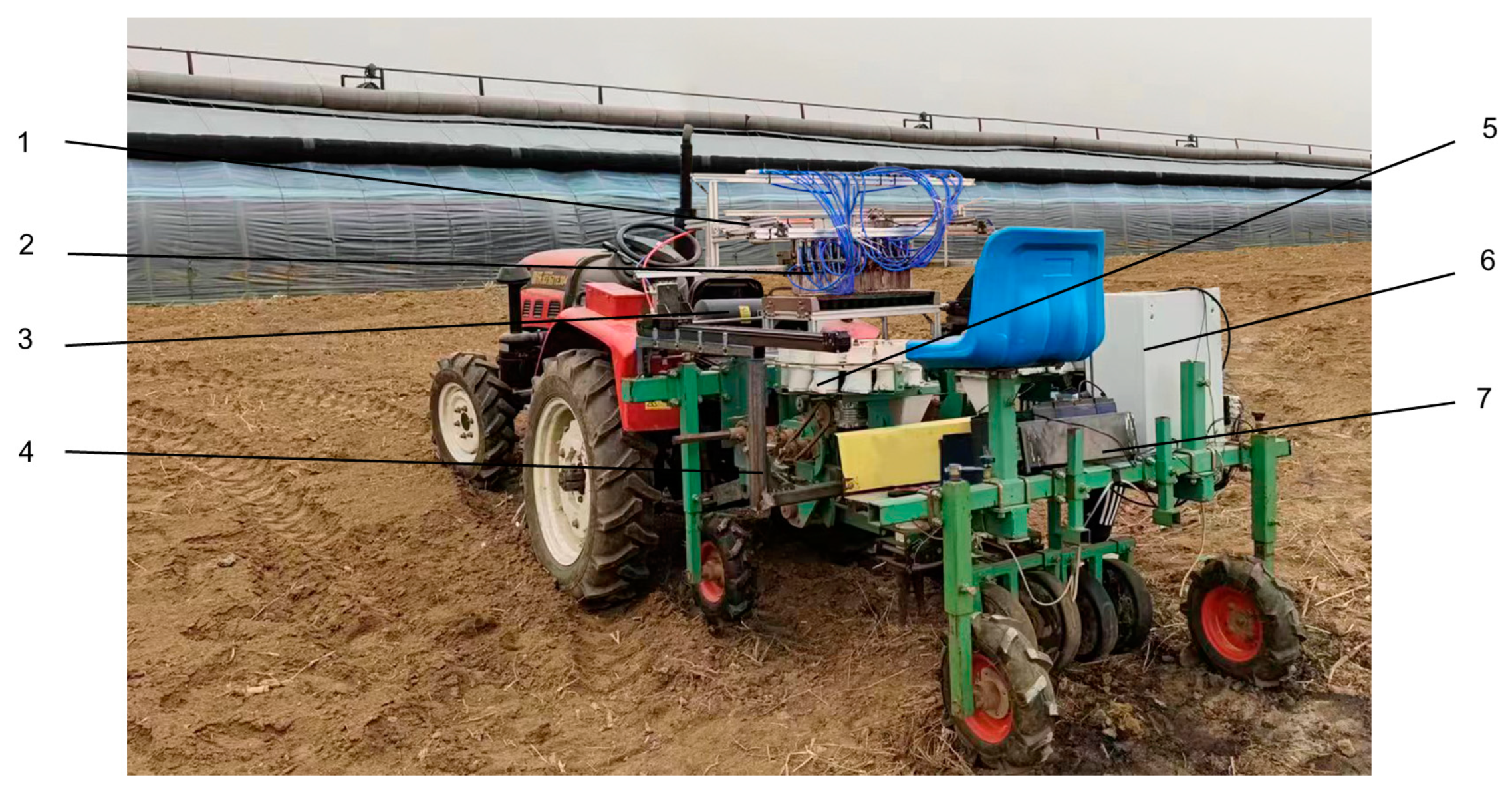
2.1. Working Principle of Automatic Transplanter
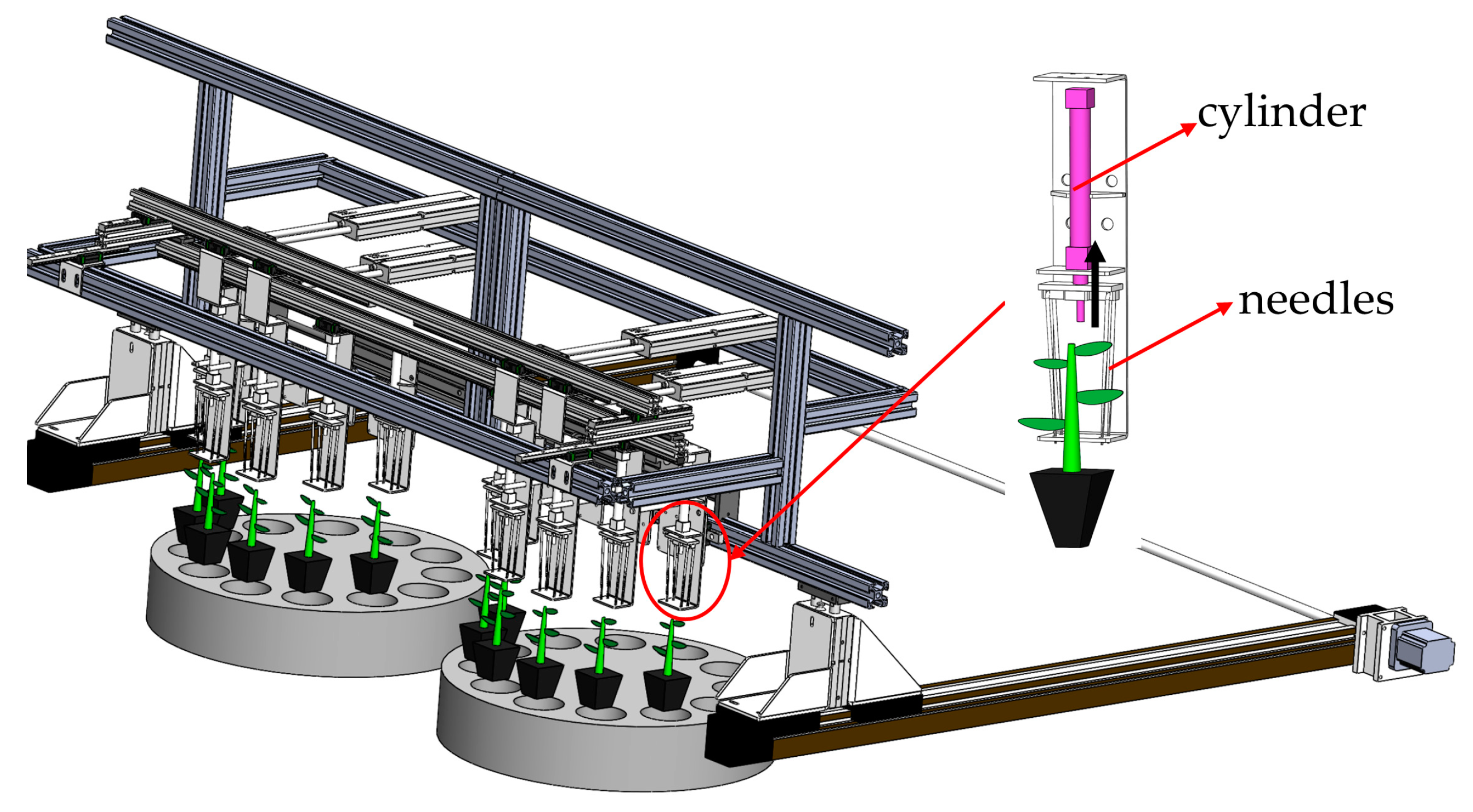
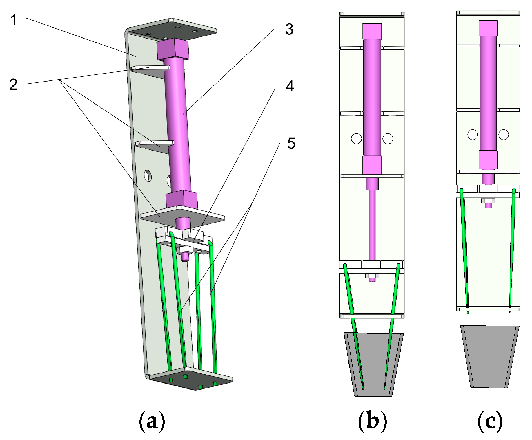
2.2. Transplanting Manipulator
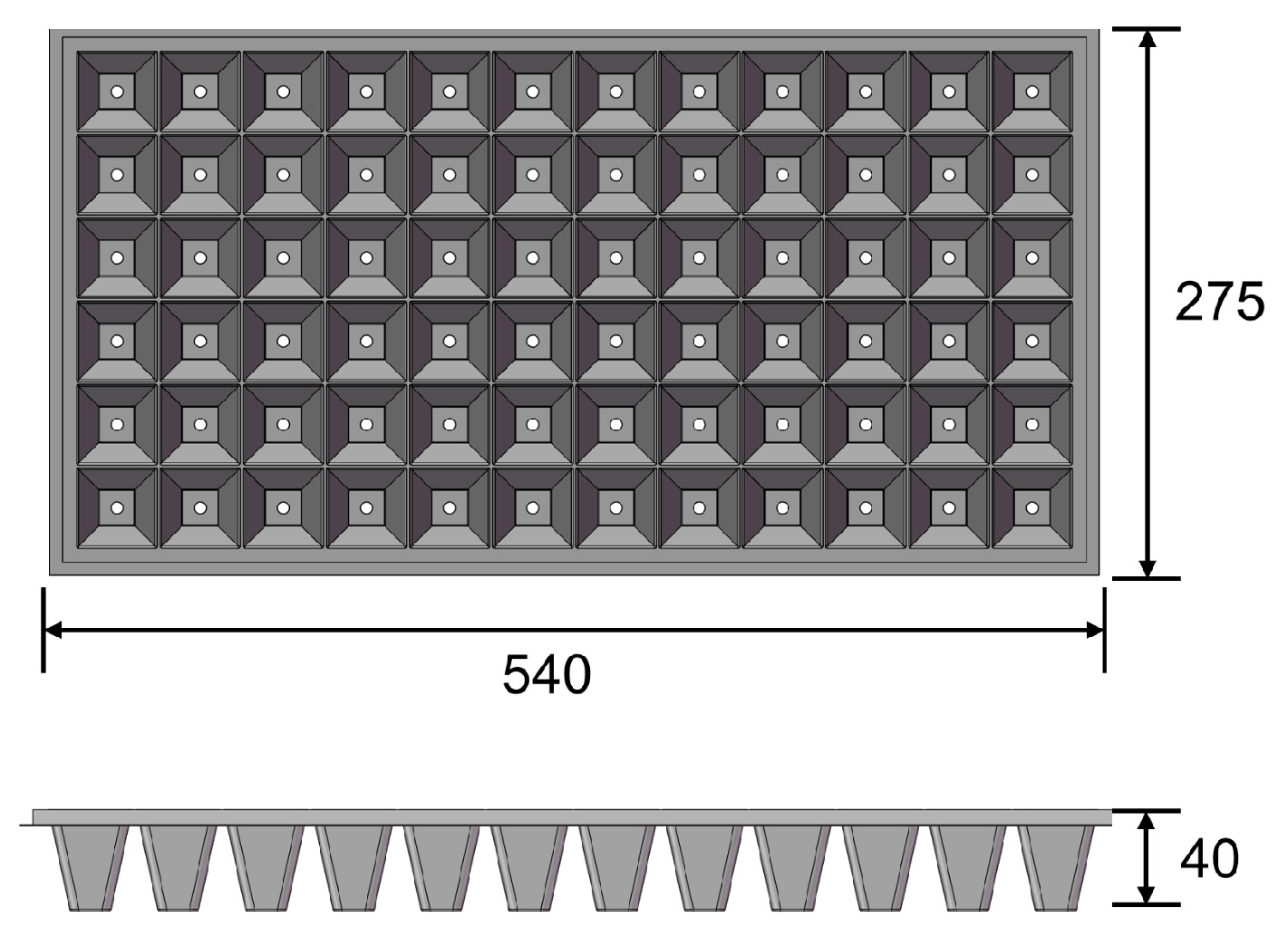
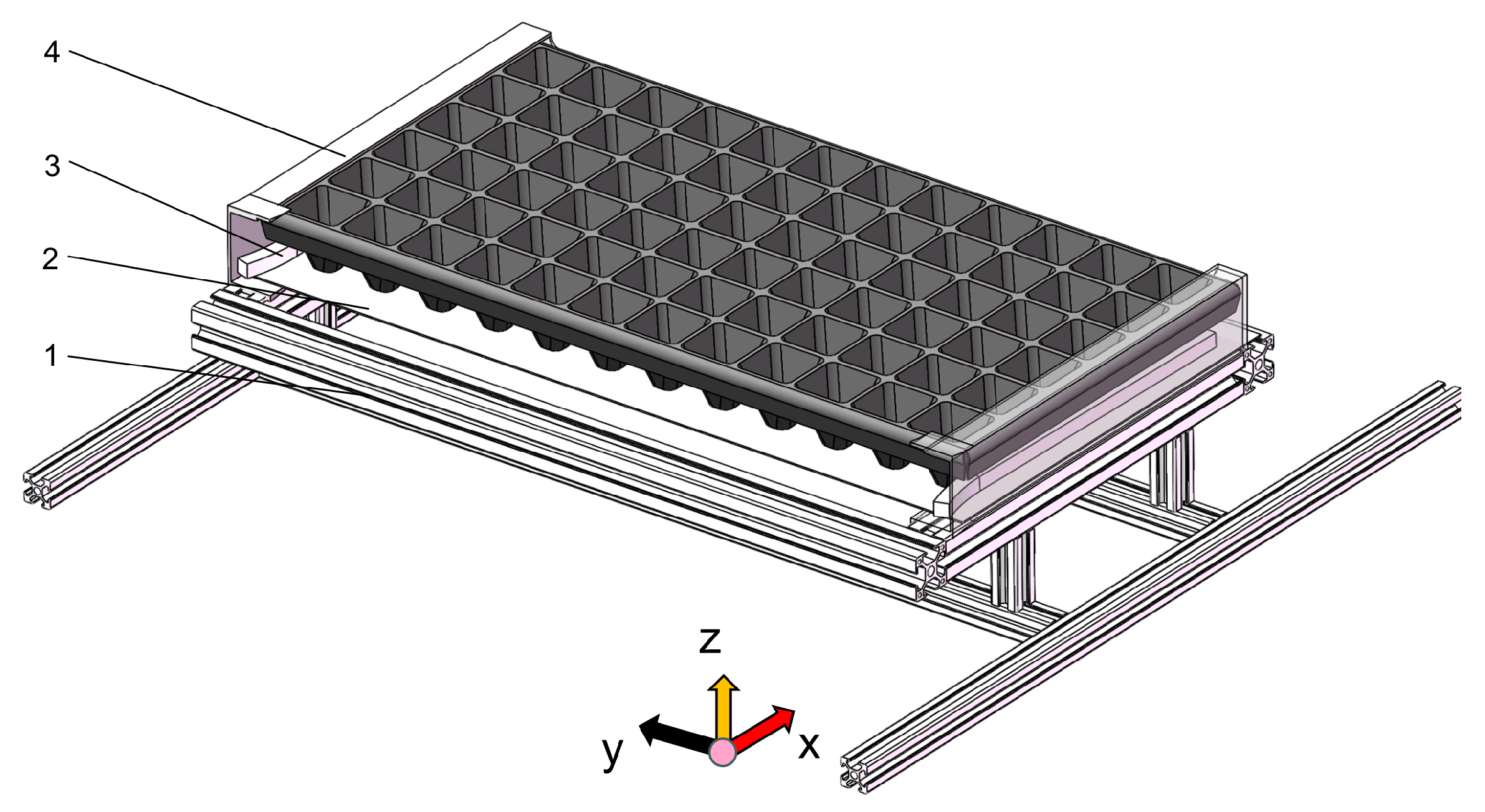
2.3. Seedling Tray Fixator
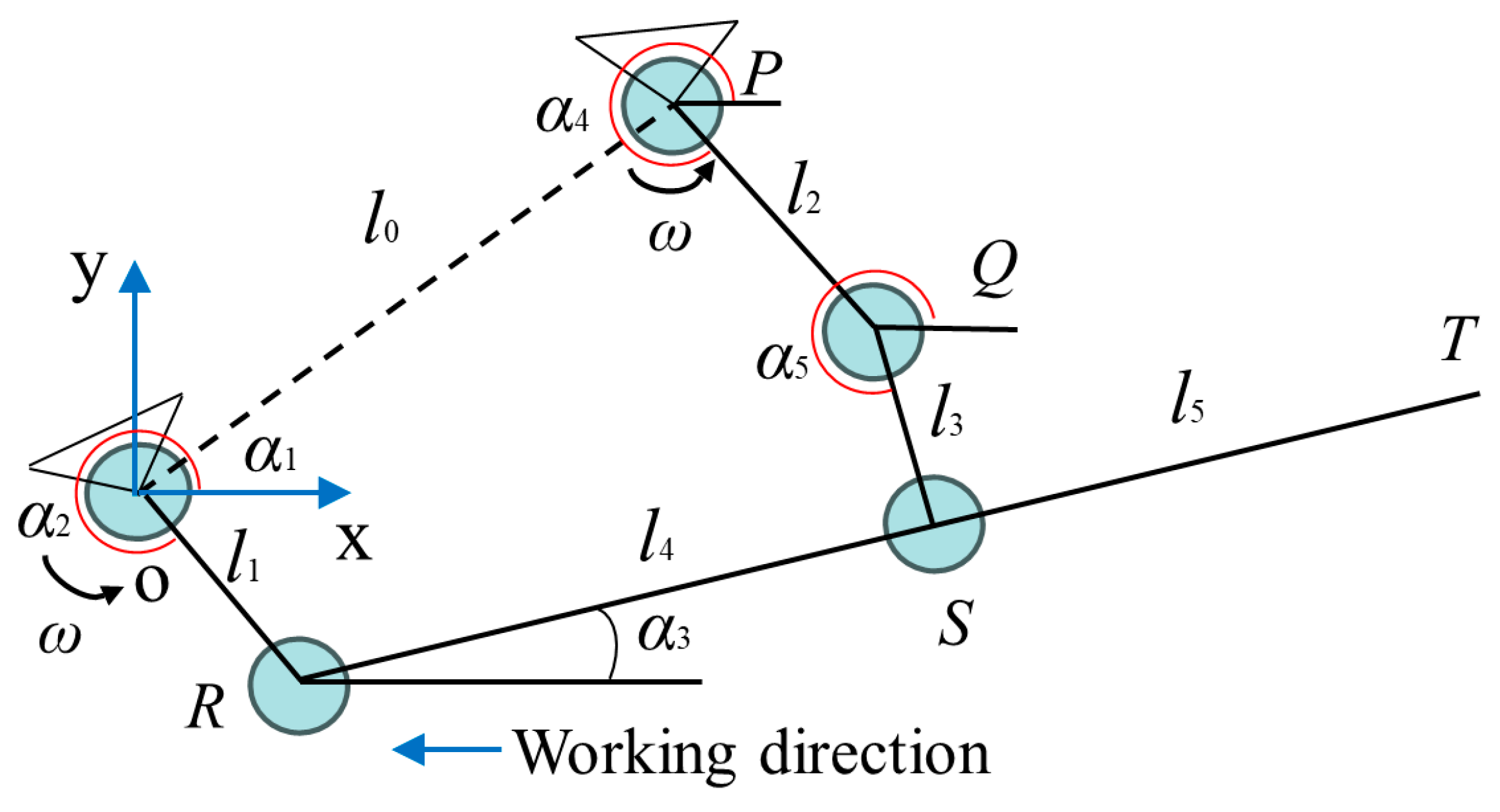
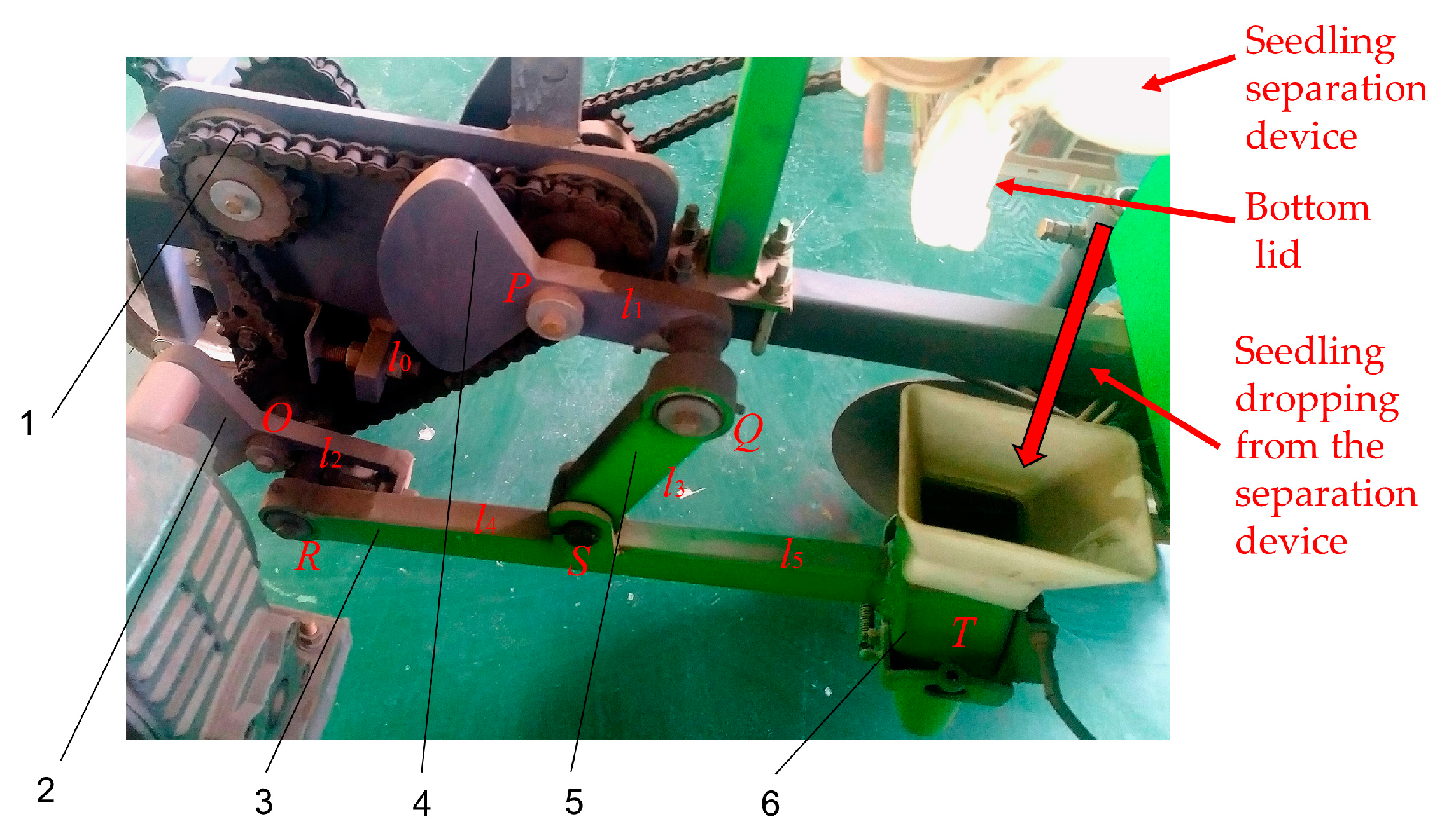
2.4. Planting Device
2.5. Power Distribution and PLC Control System
- (1)
- Power distribution
- (2)
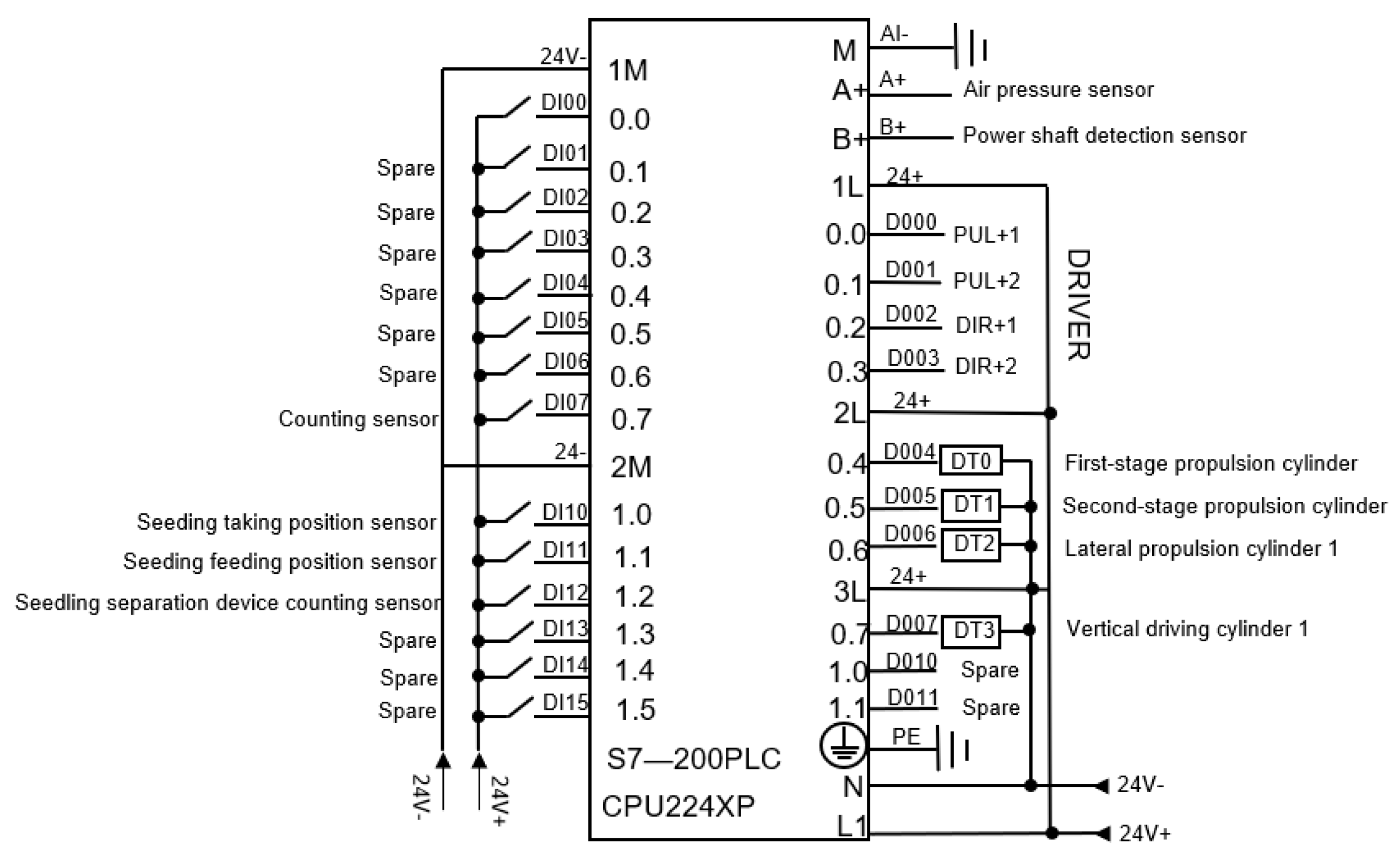
- PLC control system
3. Experiment and Analysis
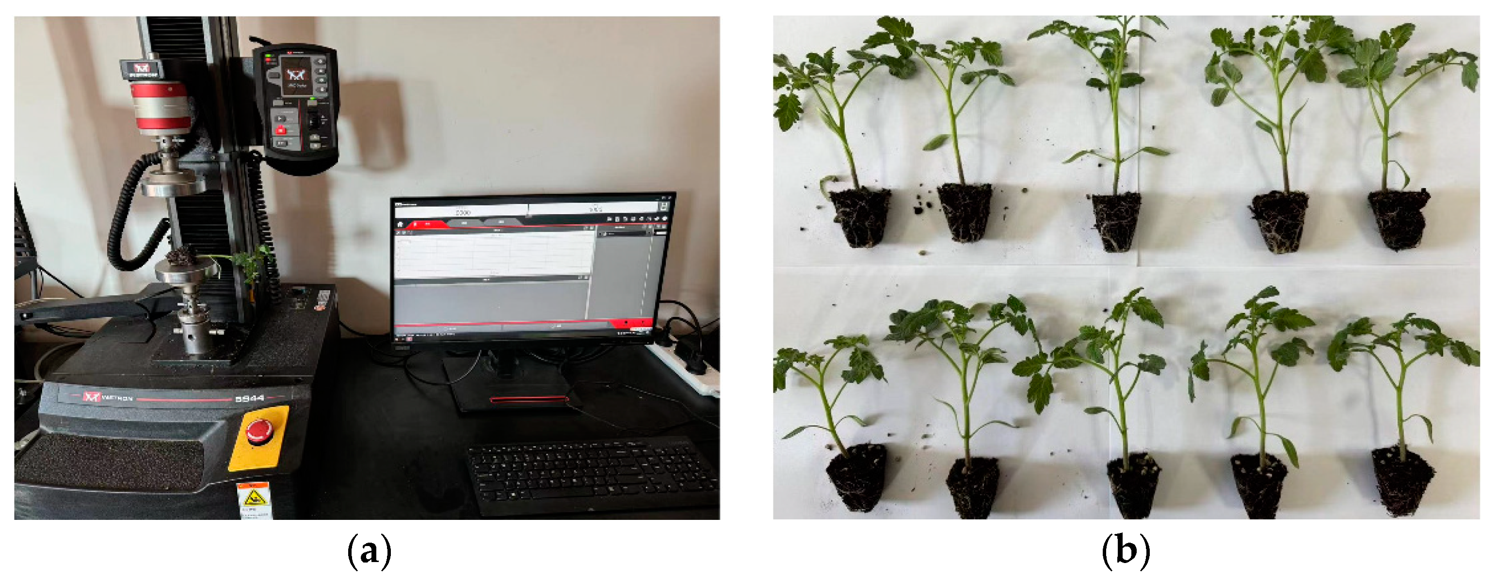
3.1. Experimental Condition
3.2. Experimental Indexes
- (1)
- Exposed seedling rate
- (2)
- Lodging seedling rate
- (3)
- Leakage seedling rate
- (4)
- Replanting seedling rate
- (5)
- Success rate
3.3. Results and Discussion
- (1)
- The planting device is affected by the vibration of the machine during the movement, which causes the seedling to collide with the planting device during the process of falling into the soil; in the process of collision, zero-speed planting was affected, resulting in an increase in the exposed seedling rate;
- (2)
- When the transplanting frequency is too fast (greater than 80 plant/(min·row)), more precise cooperation between the devices is required; the planting device completes transplanting; at the moment, the planting device is unearthed and contacts the seedling substrate, stem or leaf, resulting in an increase in the lodging rate;
- (3)
- There are a few seedlings with weak roots, so the shear resistance is poor; in the process of seedling taking, the transplanting manipulator destroys the seedlings, resulting in no seedlings in the planting device and an increase in the leakage seedling rate.

| Group Number | Number of Successful Transplanting | Number of Exposed Seedlings | Number of Lodging Seedlings | Number of Leakage Seedlings | Number of Replanting Seedlings |
|---|---|---|---|---|---|
| 1 | 201 | 4 | 6 | 3 | 2 |
| 2 | 202 | 5 | 4 | 4 | 1 |
| 3 | 204 | 4 | 3 | 3 | 2 |
| 4 | 202 | 5 | 4 | 3 | 2 |
| 5 | 205 | 3 | 4 | 4 | 0 |
| Group Number | Success Rate/% | Exposed Seedling Rate/% | Lodging Seedling Rate/% | Leakage Seedling Rate/% | Replanting Seedling Rate/% |
|---|---|---|---|---|---|
| 1 | 93.05 | 1.85 | 2.78 | 1.39 | 0.93 |
| 2 | 93.52 | 2.31 | 1.85 | 1.85 | 0.46 |
| 3 | 94.44 | 1.85 | 1.39 | 1.39 | 0.93 |
| 4 | 93.52 | 2.31 | 1.85 | 1.39 | 0.93 |
| 5 | 94.91 | 1.39 | 1.85 | 1.85 | 0 |
4. Conclusions
- (1)
- When the extraction force of the transplanting manipulator is too large, it will cause shear damage to the seedlings.
- (2)
- The experimental results showed that when the planting frequency was 80 plants/(min·row), the transplanting success rate was 93.89%, the missed planting rate was 1.58%, the replanting rate was 0.65%, the lodging rate was 1.94%, and the exposed seedling rate was 1.94%. The machine met the operation requirements.
Author Contributions
Funding
Data Availability Statement
Acknowledgments
Conflicts of Interest
References
- Ankit, S.; Sanjay, K. Design and development of a vegetable plug seedling transplanting mechanism for a semi-automatic transplanter. Sci. Hortic. 2024, 326, 112773. [Google Scholar]
- Vlahidis, V.; Roșca, R.; Cârlescu, P.M. Evaluation of the Functional Parameters for a Single-Row Seedling Transplanter Prototype. Agriculture 2024, 14, 388. [Google Scholar] [CrossRef]
- Wu, W.; Zhang, Z.; Zhang, X.; He, Y.; Fang, H. Application of visual inertia fusion technology in rice transplanter operation. Comput. Electron. Agric. 2024, 221, 108990. [Google Scholar] [CrossRef]
- Ji, D.; Tian, S.; Wu, H.; Zhao, B.; Gong, Y.; Ma, J.; Zhou, M.; Liu, W. Design and experimental verification of an automatic transplant device for a self-propelled flower transplanter. J. Braz. Soc. Mech. Sci. Eng. 2023, 45, 420. [Google Scholar] [CrossRef]
- Syed, T.N.; Jizhan, L.; Xin, Z.; Shengyi, Z.; Yan, Y.; Mohamed, S.H.A.; Lakhiar, I.A. Seedling-lump integrated non-destructive monitoring for automatic transplanting with Intel RealSense depth camera. Artif. Intell. Agric. 2019, 3, 18–32. [Google Scholar] [CrossRef]
- Hwang, H.; Sistler, F.E. A robotic pepper transplanter. Appl. Eng. Agric. 1986, 2, 2–5. [Google Scholar] [CrossRef]
- Tmg, K.; Giacomelli, G.; Shen, S. Robot workcell for transplanting of seedlings part I-layout and materials flow. Trans. ASAE 1990, 33, 1005–1010. [Google Scholar] [CrossRef]
- Jin, X.; Tang, L.; Li, R.; Zhao, B.; Ji, J.; Ma, Y. Edge recognition and reduced transplantation loss of leafy vegetable seedlings with Intel RealsSense D415 depth camera. Comput. Electron. Agric. 2022, 198, 107030. [Google Scholar] [CrossRef]
- Li, M.; Xiao, L.; Ma, X.; Yang, F.; Jin, X.; Ji, J. Vision-based a seedling selective planting control system for vegetable transplanter. Agriculture 2022, 12, 2064. [Google Scholar] [CrossRef]
- Ye, B.; Zeng, G.; Deng, B.; Yang, C.; Liu, J.; Yu, G. Design and tests of a rotary plug seedling pick-up mechanism for vegetable automatic transplanter. Int. J. Agric. Biol. Eng. 2020, 13, 70–78. [Google Scholar] [CrossRef]
- Tsuga, K. Development of fully automatic vegetable transplanter. Jpn. Agric. Res. Q. 2000, 34, 21–28. [Google Scholar]
- Mazzetto, F.; Calcante, A. Highly automated vine cutting transplanter based on DGNSS-RTK technology integrated with hydraulic devices. Comput. Electron. Agric. 2011, 79, 20–29. [Google Scholar] [CrossRef]
- Kumar, P.; Raheman, H. Automatic feeding mechanism of a vegetable transplanter. Int. J. Agric. Biol. Eng. 2012, 5, 20–27. [Google Scholar]
- Tong, J.; Shi, H.; Wu, C.; Jiang, H.; Yang, T. Skewness correction and quality evaluation of plug seedling images based on Canny operator and Hough transform. Comput. Electron. Agric. 2018, 155, 461–472. [Google Scholar] [CrossRef]
- Liu, D.; Gong, Y.; Zhang, X.; Chen, X.; Wang, G.; Zhang, X. Design and experiment of dry-farming cantaloupe transplanter under water. Agriculture 2022, 12, 796. [Google Scholar] [CrossRef]
- Li, B.; Gu, S.; Chu, Q.; Yang, Y.; Xie, Z.; Fan, K.; Liu, X. Development of transplanting manipulator for hydroponic leafy vegetables. Int. J. Agric. Biol. Eng. 2019, 12, 38–44. [Google Scholar] [CrossRef]
- Jin, X.; Li, M.; Li, D.; Ji, J.; Pang, J.; Wang, J.; Peng, L. Development of automatic conveying system for vegetable seedlings. EURASIP J. Wirel. Commun. Netw. 2018, 2018, 1–9. [Google Scholar] [CrossRef]
- Ji, J.; Cheng, Q.; Jin, X.; Zhang, Z.; Xie, X.; Li, M. Design and test of 2ZLX-2 transplanting machine for oil peony. Int. J. Agric. Biol. Eng. 2020, 13, 61–69. [Google Scholar] [CrossRef]
- Paradkar, V.; Raheman, H.; Rahul, K. Development of a metering mechanism with serial robotic arm for handling paper pot seedlings in a vegetable transplanter. Artif. Intell. Agric. 2021, 5, 52–63. [Google Scholar] [CrossRef]
- Jiang, Z.; Hu, Y.; Jiang, H.; Tong, J. Design and force analysis of end-effector for plug seedling transplanter. PLoS ONE 2017, 12, e0180229. [Google Scholar] [CrossRef]
- Xie, S.; Yang, S.; Liu, J. Development of the seedling taking and throwing device with oblique insertion and plug clipping for vegetable transplanters. Trans. CSAE 2020, 36, 1–10. [Google Scholar]
- Cheng, C.; Lin, J.; Zhang, H.; Wang, Q.; Xi, L.; Wang, L.; Luo, C. Design and Research of Power Battery Temperature Control by PLC. Front. Comput. Intell. Syst. 2023, 4, 63–66. [Google Scholar] [CrossRef]


| Item | Parameter | Unit | Item | Parameter | Unit |
|---|---|---|---|---|---|
| Boundary dimension (length × width × height) | 1250 × 1100 × 1550 | mm | Matching tractor model | 304 | |
| Number of operators | 2 | Row spacing | 300–500 | mm | |
| Driving pressure | 0.5 | MPa | Total weight | 423 | Kg |
| Frequency | 80 | plants/min·row | Battery voltage | 24 | V |
| Group One | Group Two | ||||
|---|---|---|---|---|---|
| Order | Adhesion Force/N | Water Content/% | Order | Adhesion Force/N | Water Content/% |
| 1 | 5.86 | 33.2 | 6 | 5.02 | 26.9 |
| 2 | 5.63 | 31.5 | 7 | 5.68 | 33.1 |
| 3 | 5.72 | 33.1 | 8 | 5.07 | 27.6 |
| 4 | 5.15 | 28.2 | 9 | 6.17 | 37.5 |
| 5 | 6.26 | 37.4 | 10 | 5.42 | 31.2 |
Disclaimer/Publisher’s Note: The statements, opinions and data contained in all publications are solely those of the individual author(s) and contributor(s) and not of MDPI and/or the editor(s). MDPI and/or the editor(s) disclaim responsibility for any injury to people or property resulting from any ideas, methods, instructions or products referred to in the content. |
© 2024 by the authors. Licensee MDPI, Basel, Switzerland. This article is an open access article distributed under the terms and conditions of the Creative Commons Attribution (CC BY) license (https://creativecommons.org/licenses/by/4.0/).
Share and Cite
Ji, D.; Liu, L.; Zeng, F.; Zhang, G.; Liu, Y.; Diao, H.; Tian, S.; Zhao, Z. Design and Experimental Study of a Traction Double-Row Automatic Transplanter for Solanum Lycopersicum Seedlings. Horticulturae 2024, 10, 692. https://doi.org/10.3390/horticulturae10070692
Ji D, Liu L, Zeng F, Zhang G, Liu Y, Diao H, Tian S, Zhao Z. Design and Experimental Study of a Traction Double-Row Automatic Transplanter for Solanum Lycopersicum Seedlings. Horticulturae. 2024; 10(7):692. https://doi.org/10.3390/horticulturae10070692
Chicago/Turabian StyleJi, Dong, Limin Liu, Fandi Zeng, Guangteng Zhang, Yinzeng Liu, Hongwei Diao, Subo Tian, and Zhihuan Zhao. 2024. "Design and Experimental Study of a Traction Double-Row Automatic Transplanter for Solanum Lycopersicum Seedlings" Horticulturae 10, no. 7: 692. https://doi.org/10.3390/horticulturae10070692