Article

Direct Observation of Short Large-Amplitude Magnetic Field Structures from Formation to Destruction

1
School of Mathematics and Statistics, Shandong University, Weihai 264209, China
2
Shandong Provincial Key Laboratory of Optical Astronomy and Solar-Terrestrial Environment, Institute of Space Sciences, Shandong University, Weihai 264209, China
*
Authors to whom correspondence should be addressed.
Magnetochemistry 2024, 10(8), 54; https://doi.org/10.3390/magnetochemistry10080054
Submission received: 5 July 2024 / Revised: 21 July 2024 / Accepted: 24 July 2024 / Published: 29 July 2024
(This article belongs to the Special Issue New Insight into the Magnetosheath)

Abstract

:
Short large-amplitude magnetic field structures (SLAMSs) are often seen upstream of quasi-parallel shocks. They play vital roles near the quasi-parallel shock, such as decelerating solar wind ions and contributing to the dissipation and reformation of the shock. The formation process of these structures has attracted great attention and has long been realized in simulation. However, their formation mechanism is still full of mysteries. Here, using magnetospheric multiscale mission (MMS) observation, we provide direct observations of the SLAMS formation and destruction processes. SLAMS growth is powered by solar wind ions and shock-reflected ions through the ion-ion non-resonant mode. Reconnection occurs between and inside SLAMSs during their growth; however, these cumulative changes in magnetic field topology and the dissipation of the magnetic field energy contribute to the destruction of the SLAMS. These observations shed new light on the dissipation and reformation of the shock both in space physics and astrophysics.

1. Introduction

Collisionless shocks are commonly observed in space physics [1,2,3]. When the plasma’s kinetic energy exceeds the shock’s dissipation limit, a portion is reflected upstream, exciting different ion-ion two-stream instabilities [4]. This interaction generates ultra-low frequency (ULF) waves and leads to the formation of different kinds of non-linear compressional magnetic structures [5,6,7,8].
SLAMSs stand out among these structures and play crucial roles near the shock [9,10,11]. They exhibit substantial magnetic field enhancements (δB/B0 > 2 [12], where δB is the magnetic field enhancement and B0 is the background magnetic field). Similar to the quasi-perpendicular shocks, SLAMSs decelerate, thermalize, and reflect solar wind ions in the foreshock region [13,14,15]. In addition, SLAMSs contribute to electron acceleration and generation of whistler-mode waves [16,17], shock dissipation and reformation [18,19], magnetic reconnection [20,21,22,23,24,25,26,27], and energy cascades within the turbulence at the quasi-parallel shock [28], leading to the downstream generation of a magnetosheath high-speed jet [29,30,31].
Based on theoretical and numerical studies of the evolution of SLAMSs [4,32], SLAMSs can be generated by different modes of ion-ion two-stream instabilities: the ion-ion right-hand non-resonant mode [33,34] and the ion-ion right-hand and left-hand resonant mode [35,36]. The distinctions among these modes lie in the wave period, polarization, and propagation direction in the plasma rest frame. SLAMSs undergo significant steepening near the bow shock [37,38]. Their convection speed (relative to the bow shock) decreases with increasing amplitude and decreasing distance to the bow shock [12,39]. SLAMS formation has been long realized in simulation [6,40,41]. Research using hybrid simulations has found that SLAMSs can be created by electromagnetic ion/ion beam instabilities [7,8,34]. Meanwhile, particle-in-cell (PIC) simulations suggest that shocklets and SLAMSs can arise from a nonlinear interaction between gradients in ion densities and the ULF wave field [40,41]. However, cluster observation reveals fundamentally different properties between SLAMSs and ULF-related structures [10,11]. By comparing the analytical approximations [4,34] with wind observation, Wilson et al. [15] argue that the ion-ion instability, while reaching saturation, is insufficient to account for the strong magnetic fields observed in SLAMSs. Recent findings from the magnetospheric multiscale (MMS) mission shed light on this phenomenon. Chen et al. [42] suggests that the anomalous resonance between solar wind ions and ULF waves could play a pivotal role in the magnetic amplification from quasi-sinusoidal waves to SLAMSs.
The formation mechanism of SLAMSs is still full of mysteries. However, direct in-situ satellite observation following the rise and fall of individual SLAMSs has not been reported in the literature. In this paper, using unprecedented MMS observation [43,44,45,46,47] when MMS 1–4 are positioned in a single line, we provide direct observations of the rise and fall of SLAMSs.

2. Data

The data used in this study is obtained from the MMS1–4 satellite burst-mode observation. The solar wind data is obtained from the OMNI data set. Since the ion moment data from MMS in the solar wind might not be so reliable, the drift bi-Maxwellian distribution is used to fit the observed ion distribution using the equation shown below.
f i o n V   , V = n i o n π 3 / 2 V t h V t h 2 e x p V V d r i f t 2 V t h 2 V V d r i f t 2 V t h 2
where V t h and   V d r i f t denote the ion thermal speed and ion drift speed, respectively. ∥ and ⊥ denote the velocity parallel and perpendicular to the local magnetic field.

3. Results

Figure 1 shows four satellite MMS burst-mode observations on 30 January 2019, from 14:47:43.5 to 14:47:55 UT. The MMS constellation is positioned near the quasi-parallel bow shock (Figure 1i, θ B N = 20 ° and MA = 14.8). θ B N represents the angle between the interplanetary magnetic field vector (OMNI data set: [1.81, 1.16, 0.77] nT in GSM) and the bow shock normal (determined via a model [48]). MA is the solar wind Alfvén Mach number. The four MMS spacecraft align in a line. After MMS3 encountered SLAMSs first, MMS4 followed, then MMS1, and finally MMS2. Figure 1 shows their encounters from top to bottom in this order. To display the SLAMSs evolution clearly, the four satellite observations are time-shifted with respect to the MMS3 time series. The lag time ( Δ t = 2.1   s ) between MMS3 and MMS4 is determined based on the correlation coefficient (cc = 0.88 when Δ t = 2.1   s ) between the profile of the magnetic field from MMS3 and time shifted MMS4 observation. For MMS1 and MMS2, the lag time is determined by the distance to MMS3 and the propagation velocity of the SLAMSs. The propagation velocity of these SLAMSs in GSM coordinates is obtained [−168.0, 29.8, −48.5] km/s using the lag time and satellite separation between MMS3 and MMS4.
Figure 1b shows that MMS3 detects solar wind ion beams and the ion beams reflected by the bow shock or SLAMSs. In each case, their bulk velocity Vx is overlaid on the reduced ion distribution in the plot. Later observations by MMS4 and MMS1 (Figure 1d,f), show that both populations are thermalized presumably due to the ULF waves generated by the ion-ion two-stream instability, eventually merging into one population observed by MMS2 (Figure 1h). Simultaneously, SLAMS 1 (14:47:46.5 to 14:47:49 UT) and SLAMS 2 (14:47:51.5 to 14:47:53 UT) experience intense steepening based on the comparison of MMS3 and MMS1 observation, identified by enhanced magnetic fields (SLAMS 1: δB/B0 = 3.69, B0 = 3.91 nT; SLAMS 2: δB/B0 =2.90, B0 = 5.25 nT) and solar wind ion deceleration (Figure 1d, f, at 14:47:47.4 UT for SLAMS 1 and 14:47:51.4 UT for SLAMS 2).
Between these two SLAMSs, the rise and fall of an additional SLAMS, (labelled SLAMS 3, 14:47:49.9 to 14:47:51.4 UT, highlighted in the yellow shaded region) is observed by the MMS constellation, starting as the leading edge of SLAMS 2 in MMS3, evolving into a steepened ULF wave (δB/B0 = 1.79, B0 = 3.91 nT) observed by MMS4 after approximately two seconds, becoming a SLAMS (δB/B0 = 2.81, B0 = 3.91 nT) observed by MMS1 after three seconds, and eventually breaking up rapidly as observed by MMS2.
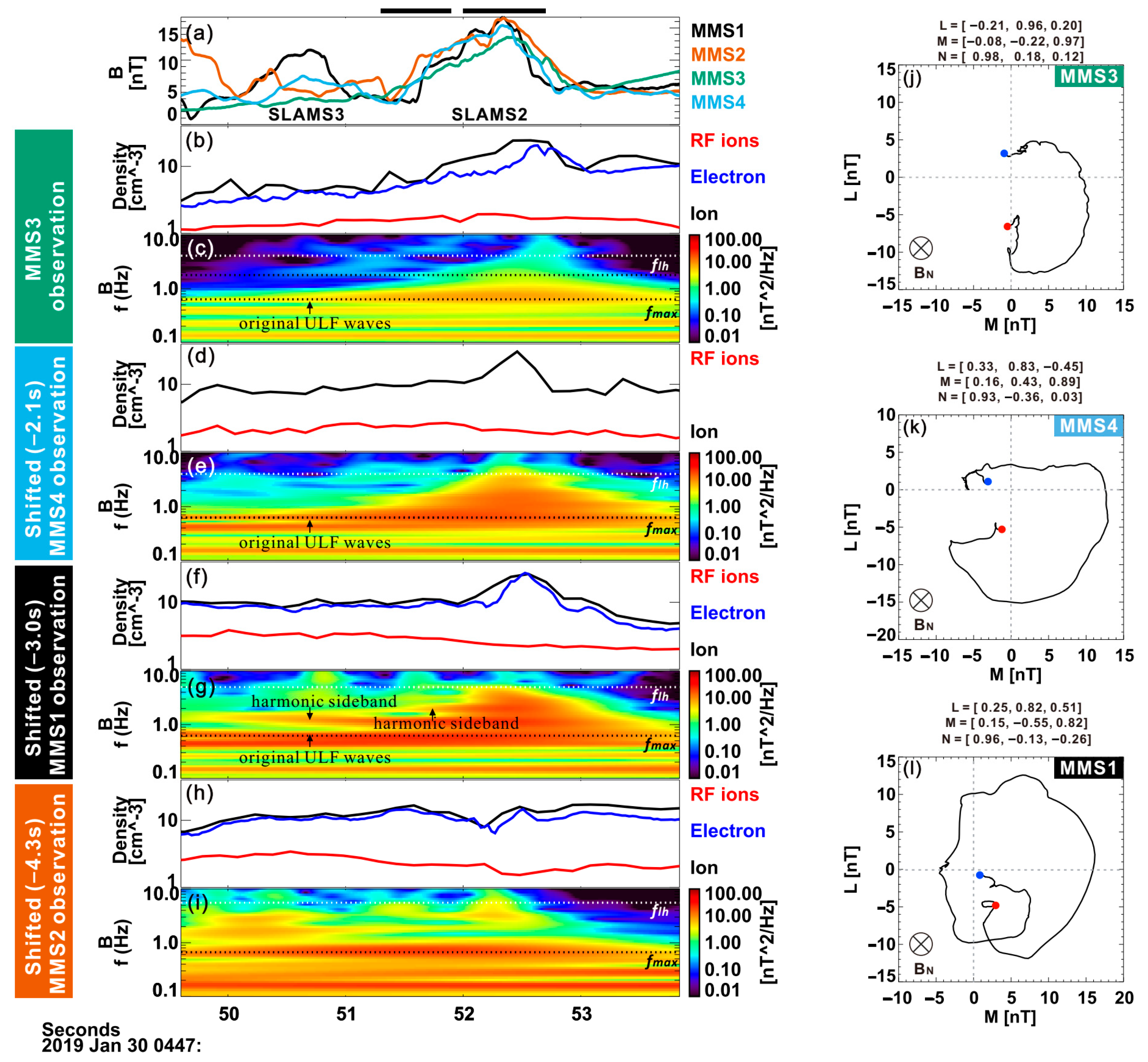
Figure 2 shows the wavelet analysis of the magnetic field observed by four MMS satellites during the time periods of SLAMS 3 and SLAMS 2 (identified by the enhanced magnetic field and density in Figure 2). The wavelet analysis shows that the wave frequency with maximum amplitude f m a x   ( f m a x   = 0.65   Hz = 2.83   f c i black dashed lines in Figure 2, ion gyro-frequency f c i   = 0.23   Hz   ) falls within the expected ULF wave range generated by the non-resonant mode. In the spacecraft reference frame, the ULF wave polarization, analyzed through the hodograms of the magnetic field in the L-M plane (shown in Figure 2j–l), consistently exhibits right-hand circular polarization during the SLAMS 3 evolution. The L-M-N coordinates of the SLAMSs are determined by the minimum variance analysis of the magnetic field [49,50]. During the steepening, ULF waves with frequencies several times the f m a x are generated ( f 1 .4, 2.1 Hz) and superimposed on the original ULF wave (Figure 2 e,g within SLAMS 3 and SLAMS 2). These waves, having similar amplitudes and phase velocities to the original ULF waves, are harmonic sidebands. They, in turn, generate their own harmonic sidebands during the steepening process [28,51]. Subsequently, SLAMS 3 forms due to the steepening of these ULF waves. During the MMS2 observation, although strong ULF waves near the f m a x persist (Figure 2i), the harmonic sidebands between f m a x and lower-hybrid frequencies (black and white dashed lines in Figure 2) are weaker (Figure 2f) while the wave below f m a x becomes stronger. These observational features are consistent with the evolution of SLAMSs generated using the ion-ion non-resonant mode in simulations [34]. The SLAMSs generated through the ion-ion non-resonant mode are subject to a parameter decay and tend to form a state of condensate where the turbulence becomes nearly monochromatic [34].
In addition, key parameters determining the modes of the ion-ion two-stream instability are the density ratio and relative drift between the solar wind and reflected ions. The velocity and density of the two ion populations (nrf/nsw = 0.31 and Δ V   = 339.53 km/s~8.0 VAlfvén from MMS observation, nrf/nsw = 0.28 and Δ V   = 232.59 km/s~5.5 VAlfvén from bi-Maxwellian fitting, VAlfvén = 42.41 km/s) reveal favorable conditions for the excitation of the ion-ion right-hand non-resonant mode (modest density ratio and high relative drift Δ V V A , see details in Table 2 from [4]). The phase velocity of the ULF wave ( V p h _ x = ω / k x 280   km / s ) and the wave vector k ( k d i = 0.36 ,   ion   inertial   length   d i = 116.84   km ) are determined based on the band-pass filtered magnetic field B and electric field E (0.3~2 Hz) through linearized Faraday’s law ( k × E = ω B ). The ω is determined based on the f m a x in wavelet analysis Figure 2e. Therefore, the ULF wave propagates toward Earth in the solar wind reference frame ( V s w _ x = 251 ~ 240   km / s in the spacecraft reference frame based on drift bi-Maxwellian fitting and MMS observation). Therefore, the ULF wave is Earthward, propagating in the solar wind rest frame generated through the ion-ion non-resonant mode.
To confirm the generation mechanism, we also used the linear dispersion solver BO [52] to solve the dispersion relation. The input plasma parameters are obtained via drift bi-Maxwellian fitting of the ion distribution (as shown in Figure 3). We only used the fitting results of MMS3 observations during the SLAMS 3 interval (yellow shaded area in Figure 1), which is the only satellite that observed ULF waves in the linear state. The detail parameters can be found in Table 1. Corresponding to input plasma parameters, only the ion-ion non-resonant mode has a positive growth rate. The dispersion relation of the ion-ion non-resonant mode is presented in Figure 4, which is consistent with the MMS observation. We also compare the enhanced magnetic fields (δB/B0) with the saturation amplitude of the ion-ion non-resonant mode based on the analytical approximations [34] from δ   B B 0   ~ n _ r f n _ s w ^ 1 2   V _ d r i f t _ r f V _ t h _ S W using the parameters in Table 1. The observed enhancement is lower than the saturation amplitude as shown in Table 1, indicating that the ion-ion non-resonant mode is sufficient to drive the formation of SLAMS 3 observed by MMS.
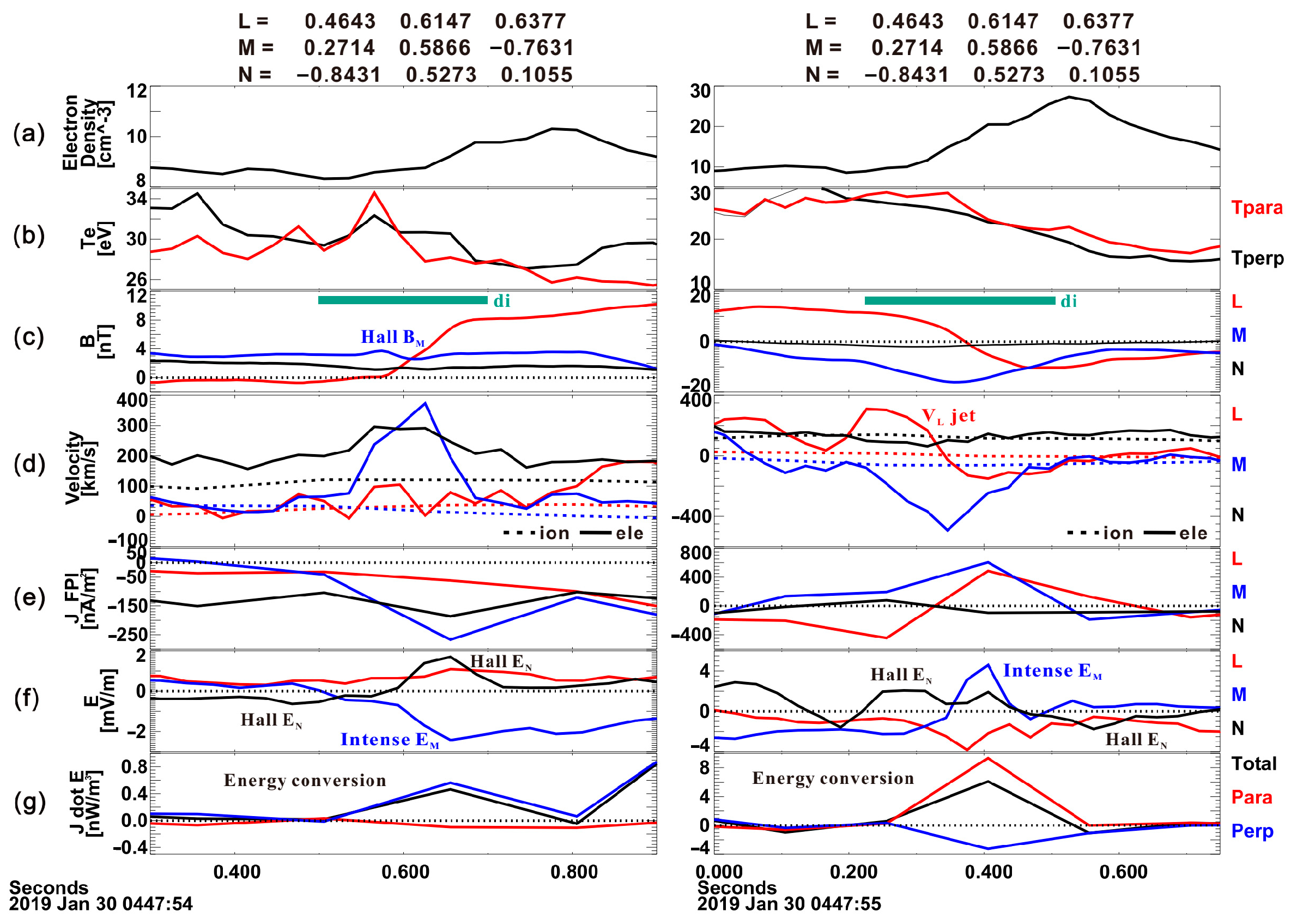
Numerical simulations in previous studies have shown that the ion-ion non-resonant mode can generate current sheets inside SLAMSs and trigger magnetic reconnection [20,21]. Here, reconnection processes are identified by MMS1 (Figure 5) not only inside SLAMS 2 but also between SLAMS 3 and SLAMS 2. The magnetic reconnection may contribute to the destruction of the SLAMSs. Magnetic reconnection is characterized by high-speed electron flow ( V L > 100   km / s ,     V M > 300   km / s , VAlfvén = 36.35 km/s) and an intense reconnection electric field along the M direction, hall electric field along the N direction, and energy conversion at the current sheet (Figure 5). There is no significant electron heating (Figure 5b) and ion jet while crossing the current sheet (Figure 5d), and the current sheet thickness is below the ion inertia length (green bars in Figure 5c). These observational features are consistent with the electron-only reconnection process, while ions do not participate in these magnetic reconnection processes [53,54]. However, as magnetic field topology changes during reconnection, local conditions are no longer suitable for the nonlinear evolution of the ion-ion non-resonant mode, resulting in a reduction in the free energy of harmonic sidebands. In addition, the stored energy in the magnetic field is dissipated during reconnection, which may also hasten the destruction of SLAMS 2 and SLAMS 3 observed by the MMS.

4. Conclusions

Based on MMS constellation observations, we observed the entire rise and fall of SLAMSs for the first time. The wave properties and instability analysis indicate SLAMSs steepening, driven by the ion-ion right-hand non-resonant mode. Non-linearly generated harmonic sidebands locally superimpose, while the thermalized solar wind and reflected ions provide free energy for the enhancement of the magnetic field.
As the steepening progresses, the gradient length of SLAMSs shortens [55], demagnetizing ions while electrons remain magnetized. This triggers the modified two-stream instability [56,57,58,59], generating waves near the lower-hybrid frequency (Figure 2e,g). Subsequently, dissipation and dispersion occur, which limit or balance the nonlinear process and prevent the destruction of SLAMSs. However, with an increase in the anti-parallel component of the magnetic field and a decrease in the thickness of the current sheet generated inside the SLAMS, magnetic reconnection occurs during steepening [25]. This alters the field line topology, introducing dissipation contributing to the destruction of SLAMS 3 and SLAMS 2, as recorded by MMS1 and MMS2.
In summary, this study investigates the rise and fall of SLAMSs, which reflects the formation and dissipation processes of shock waves to some extent and sheds new light on the energy conversion near the shock and shock evolution across the universe. However, the SLAMS evolution in this case is under a high Alfvén Mach number solar wind condition (MA = 14.8). Statistical analysis is required to determine whether the evolution process of SLAMSs varies under various solar wind conditions.

Author Contributions

Methodology, S.-C.B.; software, S.-C.B.; validation, S.-C.B., Q.S., and R.G.; formal analysis, S.-C.B.; investigation, S.-C.B.; writing—original draft preparation, S.-C.B.; writing—review and editing, Q.S., R.G., A.W.D., H.Z., A.T., and Y.B.; visualization, S.-C.B.; supervision, Q.S.; funding acquisition, S.-C.B., Q.S., R.G., H.Z., and A.T. All authors have read and agreed to the published version of the manuscript.

Funding

This research was funded by the National Natural Science Foundation of China (Grants No. 42225405, 42330202, and 42275135) and the Natural Science Foundation of Shandong Province (Grant No. ZR2022QD135 and ZR2023JQ016).

Data Availability Statement

The solar wind data are available from the OMNI data set from the Coordinated Data Analysis Web (CDAWeb) (https://cdaweb.gsfc.nasa.gov/sp_phys/data/omni/, accessed on 1 July 2024) The MMS data are available at MMS Science Data Center (https://lasp.colorado.edu/mms/sdc/public/about/browse/, accessed on 1 July 2024). All code used to analyze the MMS data in this study is based on the publicly available SPEDAS tools [60] (http://spedas.org/blog/, accessed on 1 July 2024).

Conflicts of Interest

The authors declare no conflicts of interest.

References

  1. Burgess, D.; Lucek, E.A.; Scholer, M.; Bale, S.D.; Balikhin, M.A.; Balogh, A.; Horbury, T.S.; Krasnoselskikh, V.V.; Kucharek, H.; Lembège, B.; et al. Quasi-parallel shock structure and processes. Space Sci. Rev. 2005, 118, 205–222. [Google Scholar] [CrossRef]
  2. Bale, S.D.; Balikhin, M.A.; Horbury, T.S.; Krasnoselskikh, V.V.; Kucharek, H.; Möbius, E.; Walker, S.N.; Balogh, A.; Burgess, D.; Lembège, B.; et al. Quasi-perpendicular shock structure and processes. Space Sci. Rev. 2005, 118, 161–203. [Google Scholar] [CrossRef]
  3. Zhang, H.; Zong, Q.G.; Connor, H.; Delamere, P.; Facskó, G.; Han, D.S.; Hasegawa, H.; Kallio, E.; Kis, A.; Le, G.; et al. Dayside Transient Phenomena and Their Impact on the Magnetosphere and Ionosphere. Space Sci. Rev. 2022, 218, 40. [Google Scholar] [CrossRef] [PubMed]
  4. Gary, S.P. Electromagnetic Ion Ion Instabilities and Their Consequences in Space Plasmas—A Review. Space Sci. Rev. 1991, 56, 373–415. [Google Scholar] [CrossRef]
  5. Hada, T.; Kennel, C.F.; Terasawa, T. Excitation of Compressional Waves and the Formation of Shocklets in the Earth’s Foreshock. J. Geophys. Res. Space Phys. 1987, 92, 4423–4435. [Google Scholar] [CrossRef]
  6. Omidi, N.; Winske, D. Steepening of Kinetic Magnetosonic Waves into Shocklets—Simulations and Consequences for Planetary Shocks and Comets. J. Geophys. Res. Space Phys. 1990, 95, 2281–2300. [Google Scholar] [CrossRef]
  7. Dubouloz, N.; Scholer, M. 2-Dimensional Simulations of Magnetic Pulsations Upstream of the Earth’s Bow Shock. J. Geophys. Res. Space Phys. 1995, 100, 9461–9474. [Google Scholar] [CrossRef]
  8. Onsager, T.G.; Winske, D.; Thomsen, M.F. Interaction of a Finite-Length Ion-Beam with a Background Plasma—Reflected Ions at the Quasi-Parallel Bow Shock. J. Geophys. Res. Space Phys. 1991, 96, 1775–1788. [Google Scholar] [CrossRef]
  9. Hoppe, M.M.; Russell, C.T.; Frank, L.A.; Eastman, T.E.; Greenstadt, E.W. Upstream Hydromagnetic-Waves and Their Association with Backstreaming Ion Populations—Isee-1 and Isee-2 Observations. J. Geophys. Res. Space Phys. 1981, 86, 4471–4492. [Google Scholar] [CrossRef]
  10. Lucek, E.A.; Horbury, T.S.; Balogh, A.; Dandouras, I.; Rème, H. Cluster observations of structures at quasi-parallel bow shocks. Ann. Geophys. 2004, 22, 2309–2313. [Google Scholar] [CrossRef]
  11. Lucek, E.A.; Horbury, T.S.; Dandouras, I.; Rème, H. Cluster observations of the Earth’s quasi-parallel bow shock. J. Geophys. Res. Space Phys. 2008, 113. [Google Scholar] [CrossRef]
  12. Mann, G.; Luhr, H.; Baumjohann, W. Statistical-Analysis of Short Large-Amplitude Magnetic-Field Structures in the Vicinity of the Quasi-Parallel Bow Shock. J. Geophys. Res. Space Phys. 1994, 99, 13315–13323. [Google Scholar] [CrossRef]
  13. Schwartz, S.J.; Burgess, D. Quasi-Parallel Shocks—A Patchwork of 3-Dimensional Structures. Geophys. Res. Lett. 1991, 18, 373–376. [Google Scholar] [CrossRef]
  14. Wilson, L.B. Low Frequency Waves at and Upstream of Collisionless Shocks. In Low-Frequency Waves in Space Plasmas; John Wiley & Sons: Hoboken, NJ, USA, 2016; pp. 269–291. [Google Scholar]
  15. Wilson, L.B.; Koval, A.; Sibeck, D.G.; Szabo, A.; Cattell, C.A.; Kasper, J.C.; Maruca, B.A.; Pulupa, M.; Salem, C.S.; Wilber, M. Shocklets, SLAMS, and field-aligned ion beams in the terrestrial foreshock. J. Geophys.Res. Space Phys. 2013, 118, 957–966. [Google Scholar] [CrossRef]
  16. Bai, S.C.; Shi, Q.Q.; Zhang, H.; Guo, R.L.; Shen, X.C.; Liu, T.Z.; Degeling, A.W.; Tian, A.M.; Bu, Y.D.; Zhang, S.; et al. Electron Dynamics and Whistler-Mode Waves Inside the Short Large-Amplitude Magnetic Field Structures. J. Geophys. Res. Space Phys. 2023, 128, e2023JA031816. [Google Scholar] [CrossRef]
  17. Bai, S.-C.; Shi, Q.; Shen, X.-C.; Tian, A.; Zhang, H.; Guo, R.; Wang, M.; Degeling, A.W.; Bu, Y.; Zhang, S.; et al. Whistler-Mode Waves Inside Short Large-Amplitude Magnetic Field Structures: Characteristics and Generation Mechanisms. J. Geophys. Res. Space Phys. 2024, 129, e2023JA032392. [Google Scholar] [CrossRef]
  18. Liu, T.Z.; Hao, Y.F.; Wilson, L.B.; Turner, D.L.; Zhang, H. Magnetospheric Multiscale Observations of Earth’s Oblique Bow Shock Reformation by Foreshock Ultralow-Frequency Waves. Geophys. Res. Lett. 2021, 48, e2020GL091184. [Google Scholar] [CrossRef]
  19. Johlander, A.; Battarbee, M.; Turc, L.; Ganse, U.; Pfau-Kempf, Y.; Grandin, M.; Suni, J.; Tarvus, V.; Bussov, M.; Zhou, H.Y.; et al. Quasi-Parallel Shock Reformation Seen by Magnetospheric Multiscale and Ion-Kinetic Simulations. Geophys. Res. Lett. 2022, 49, e2021GL096335. [Google Scholar] [CrossRef]
  20. Bessho, N.; Chen, L.J.; Wang, S.; Hesse, M.; Wilson, L.B. Magnetic Reconnection in a Quasi-Parallel Shock: Two-Dimensional Local Particle-in-Cell Simulation. Geophys. Res. Lett. 2019, 46, 9352–9361. [Google Scholar] [CrossRef]
  21. Bessho, N.; Chen, L.J.; Wang, S.; Hesse, M.; Wilson, L.B.; Ng, J. Magnetic reconnection and kinetic waves generated in the Earth’s quasi-parallel bow shock. Phys. Plasmas 2020, 27, 092901. [Google Scholar] [CrossRef]
  22. Gingell, I.; Schwartz, S.J.; Burgess, D.; Johlander, A.; Russell, C.T.; Burch, J.L.; Ergun, R.E.; Fuselier, S.; Gershman, D.J.; Giles, B.L.; et al. MMS Observations and Hybrid Simulations of Surface Ripples at a Marginally Quasi-Parallel Shock. J. Geophys. Res. Space Phys. 2017, 122, 11003–11017. [Google Scholar] [CrossRef]
  23. Gingell, I.; Schwartz, S.J.; Eastwood, J.P.; Burch, J.L.; Ergun, R.E.; Fuselier, S.; Gershman, D.J.; Giles, B.L.; Khotyaintsev, Y.V.; Lavraud, B.; et al. Observations of Magnetic Reconnection in the Transition Region of Quasi-Parallel Shocks. Geophys. Res. Lett. 2019, 46, 1177–1184. [Google Scholar] [CrossRef]
  24. Wang, S.; Chen, L.J.; Bessho, N.; Hesse, M.; Wilson, L.B.; Giles, B.; Moore, T.E.; Russell, C.T.; Torbert, R.B.; Burch, J.L. Observational Evidence of Magnetic Reconnection in the Terrestrial Bow Shock Transition Region. Geophys. Res. Lett. 2019, 46, 562–570. [Google Scholar] [CrossRef]
  25. Wang, S.; Chen, L.J.; Bessho, N.; Hesse, M.; Wilson, L.B.; Denton, R.; Ng, J.; Giles, B.; Torbert, R.; Burch, J. Ion-scale Current Structures in Short Large-amplitude Magnetic Structures. Astrophys. J. 2020, 898, 121. [Google Scholar] [CrossRef]
  26. Bai, S.C.; Shi, Q.Q.; Liu, T.Z.; Zhang, H.; Yue, C.; Sun, W.J.; Tian, A.M.; Degeling, A.W.; Bortnik, J.; Rae, I.J.; et al. Ion-Scale Flux Rope Observed inside a Hot Flow Anomaly. Geophys. Res. Lett. 2020, 47, e2019GL085933. [Google Scholar] [CrossRef]
  27. Liu, T.Z.; Lu, S.; Turner, D.L.; Gingell, I.; Angelopoulos, V.; Zhang, H.; Artemyev, A.; Burch, J.L. Magnetospheric Multiscale (MMS) Observations of Magnetic Reconnection in Foreshock Transients. J. Geophys. Res. Space Phys. 2020, 125, e2020JA027822. [Google Scholar] [CrossRef]
  28. Treumann, R.A. Fundamentals of collisionless shocks for astrophysical application, 1. Non-relativistic shocks. Astron. Astrophys. Rev. 2009, 17, 409–535. [Google Scholar] [CrossRef]
  29. Raptis, S.; Karlsson, T.; Plaschke, F.; Kullen, A.; Lindqvist, P.A. Classifying Magnetosheath Jets Using MMS: Statistical Properties. J. Geophys. Res. Space Phys. 2020, 125, e2019JA027754. [Google Scholar] [CrossRef]
  30. Karlsson, T.; Kullen, A.; Liljeblad, E.; Brenning, N.; Nilsson, H.; Gunell, H.; Hamrin, M. On the origin of magnetosheath plasmoids and their relation to magnetosheath jets. J. Geophys. Res. Space Phys. 2015, 120, 7390–7403. [Google Scholar] [CrossRef]
  31. Plaschke, F.; Hietala, H.; Archer, M.; Blanco-Cano, X.; Kajdic, P.; Karlsson, T.; Lee, S.H.; Omidi, N.; Palmroth, M.; Roytershteyn, V.; et al. Jets Downstream of Collisionless Shocks. Space Sci. Rev. 2018, 214, 81. [Google Scholar] [CrossRef]
  32. Wang, X.Y.; Lin, Y. Generation of nonlinear Alfven and magnetosonic waves by beam-plasma interaction. Phys. Plasmas 2003, 10, 3528–3538. [Google Scholar] [CrossRef]
  33. Winske, D.; Leroy, M.M. Diffuse Ions Produced by Electromagnetic Ion-Beam Instabilities. J. Geophys. Res. Space Phys. 1984, 89, 2673–2688. [Google Scholar] [CrossRef]
  34. Akimoto, K.; Winske, D.; Gary, S.P.; Thomsen, M.F. Nonlinear Evolution of Electromagnetic Ion-Beam Instabilities. J. Geophys. Res. Space Phys. 1993, 98, 1419–1433. [Google Scholar] [CrossRef]
  35. Gary, S.P.; Smith, C.W.; Lee, M.A.; Goldstein, M.L.; Forslund, D.W. Electromagnetic Ion-Beam Instabilities. Phys. Fluids 1984, 27, 1852–1862. [Google Scholar] [CrossRef]
  36. Le, G.; Russell, C.T. The Morphology of ULF Waves in the Earth’s Foreshock. In Solar Wind Sources of Magnetospheric Ultra-Low-Frequency Waves; John Wiley & Sons: Hoboken, NJ, USA, 1994; pp. 87–98. [Google Scholar]
  37. Scholer, M. Upstream waves, shocklets, short large-amplitude magnetic structures and the cyclic behavior of oblique quasi-parallel collisionless shocks. J. Geophys. Res. Space Phys. 1993, 98, 47–57. [Google Scholar] [CrossRef]
  38. Giacalone, J.; Schwartz, S.J.; Burgess, D. Observations of suprathermal ions in association with SLAMS. Geophys. Res. Lett. 1993, 20, 149–152. [Google Scholar] [CrossRef]
  39. Schwartz, S.J.; Burgess, D.; Wilkinson, W.P.; Kessel, R.L.; Dunlop, M.; Luhr, H. Observations of Short Large-Amplitude Magnetic-Structures at a Quasi-Parallel Shock. J. Geophys. Res. Space Phys. 1992, 97, 4209–4227. [Google Scholar] [CrossRef]
  40. Scholer, M.; Kucharek, H.; Shinohara, I. Short large-amplitude magnetic structures and whistler wave precursors in a full-particle quasi-parallel shock simulation. J. Geophys. Res. Space Phys. 2003, 108. [Google Scholar] [CrossRef]
  41. Tsubouchi, K.; Lembège, B. Full particle simulations of short large-amplitude magnetic structures (SLAMS) in quasi-parallel shocks. J. Geophys. Res. Space Phys. 2004, 109. [Google Scholar] [CrossRef]
  42. Chen, L.J.; Wang, S.; Ng, J.; Bessho, N.; Tang, J.M.; Fung, S.F.; Le, G.; Gershman, D.; Giles, B.; Russell, C.T.; et al. Solitary Magnetic Structures at Quasi-Parallel Collisionless Shocks: Formation. Geophys. Res. Lett. 2021, 48, e2020GL090800. [Google Scholar] [CrossRef]
  43. Burch, J.L.; Moore, T.E.; Torbert, R.B.; Giles, B.L. Magnetospheric Multiscale Overview and Science Objectives. Space Sci. Rev. 2016, 199, 5–21. [Google Scholar] [CrossRef]
  44. Russell, C.T.; Anderson, B.J.; Baumjohann, W.; Bromund, K.R.; Dearborn, D.; Fischer, D.; Le, G.; Leinweber, H.K.; Leneman, D.; Magnes, W.; et al. The Magnetospheric Multiscale Magnetometers. Space Sci. Rev. 2016, 199, 189–256. [Google Scholar] [CrossRef]
  45. Pollock, C.; Moore, T.; Jacques, A.; Burch, J.; Gliese, U.; Saito, Y.; Omoto, T.; Avanov, L.; Barrie, A.; Coffey, V.; et al. Fast Plasma Investigation for Magnetospheric Multiscale. Space Sci. Rev. 2016, 199, 331–406. [Google Scholar] [CrossRef]
  46. Lindqvist, P.A.; Olsson, G.; Torbert, R.B.; King, B.; Granoff, M.; Rau, D.; Needell, G.; Turco, S.; Dors, I.; Beckman, P.; et al. The Spin-Plane Double Probe Electric Field Instrument for MMS. Space Sci. Rev. 2016, 199, 137–165. [Google Scholar] [CrossRef]
  47. Ergun, R.E.; Tucker, S.; Westfall, J.; Goodrich, K.A.; Malaspina, D.M.; Summers, D.; Wallace, J.; Karlsson, M.; Mack, J.; Brennan, N.; et al. The Axial Double Probe and Fields Signal Processing for the MMS Mission. Space Sci. Rev. 2016, 199, 167–188. [Google Scholar] [CrossRef]
  48. Chao, J.K.; Wu, D.J.; Lin, C.H.; Yang, Y.H.; Wang, X.; Kesse, M.; Chen, S.H.; Lepping, R.P. Models for the size and shape of the Earth’s magnetopause and bow shock. Cospar Colloq. 2002, 12, 127–135. [Google Scholar]
  49. Sonnerup, B.U.Ö. Magnetic field reconnection. In Solar System Plasma Physics; Lanzerotti, L.J., Kennel, C.F., Parker, E.N., Eds.; North Holland: Amsterdam, The Netherlands, 1979; Volume 3. [Google Scholar]
  50. Sonnerup, B.U.Ö.; Scheible, M. Minimum and maximum variance analysis, in Analysis Methods for Multi-Spacecraft Data. In Analysis Methods for Multi-Spacecraft Data; Paschmann, G., Daly, P.W., Eds.; ESA Publications Division: Noordwijk, The Netherlands, 1998; pp. 185–220. [Google Scholar]
  51. Zahibo, N.; Slunyaev, A.; Talipova, T.; Pelinovsky, E.; Kurkin, A.; Polukhina, O. Strongly nonlinear steepening of long interfacial waves. Nonlinear Proc. Geophys. 2007, 14, 247–256. [Google Scholar] [CrossRef]
  52. Xie, H.S. BO: A unified tool for plasma waves and instabilities analysis. Comput. Phys. Commun. 2019, 244, 343–371. [Google Scholar] [CrossRef]
  53. Phan, T.D.; Eastwood, J.P.; Shay, M.A.; Drake, J.F.; Sonnerup, B.U.Ö.; Fujimoto, M.; Cassak, P.A.; Oieroset, M.; Burch, J.L.; Torbert, R.B.; et al. Electron magnetic reconnection without ion coupling in Earth’s turbulent magnetosheath. Nature 2018, 557, 202–206. [Google Scholar] [CrossRef]
  54. Lu, S.; Lu, Q.M.; Wang, R.S.; Pritchett, P.L.; Hubbert, M.; Qi, Y.; Huang, K.; Li, X.M.; Russell, C.T. Electron-Only Reconnection as a Transition From Quiet Current Sheet to Standard Reconnection in Earth’s Magnetotail: Particle-In-Cell Simulation and Application to MMS Data. Geophys. Res. Lett. 2022, 49, e2022GL098547. [Google Scholar] [CrossRef]
  55. Kennel, C.F.; Edmiston, J.P.; Hada, T. A Quarter Century of Collisionless Shock Research. In Collisionless Shocks in the Heliosphere: A Tutorial Review; American Geophysical Union: Washington, DC, USA, 1985; pp. 1–36. [Google Scholar]
  56. Muschietti, L.; Lembège, B. Two-stream instabilities from the lower-hybrid frequency to the electron cyclotron frequency: Application to the front of quasi-perpendicular shocks. Ann. Geophys. 2017, 35, 1093–1112. [Google Scholar] [CrossRef]
  57. Wu, C.S.; Zhou, Y.M.; Tsai, S.T.; Guo, S.C.; Winske, D.; Papadopoulos, K. A Kinetic Cross-Field Streaming Instability. Phys. Fluids 1983, 26, 1259–1267. [Google Scholar] [CrossRef]
  58. Mcbride, J.B.; Ott, E.; Boris, J.P.; Orens, J.H. Theory and Simulation of Turbulent Heating by Modified 2-Stream Instability. Phys. Fluids 1972, 15, 2367–2383. [Google Scholar] [CrossRef]
  59. Lemons, D.S.; Winske, D.; Gary, S.P. Non-Linear Theory and Computer-Simulation of Weibel Instability. Bull. Am. Phys. Soc. 1978, 23, 607. [Google Scholar]
  60. Angelopoulos, V.; Cruce, P.; Drozdov, A.; Grimes, E.W.; Hatzigeorgiu, N.; King, D.A.; Larson, D.; Lewis, J.W.; McTiernan, J.M.; Roberts, D.A.; et al. The Space Physics Environment Data Analysis System (SPEDAS). Space Sci. Rev. 2019, 215, 9. [Google Scholar] [CrossRef]
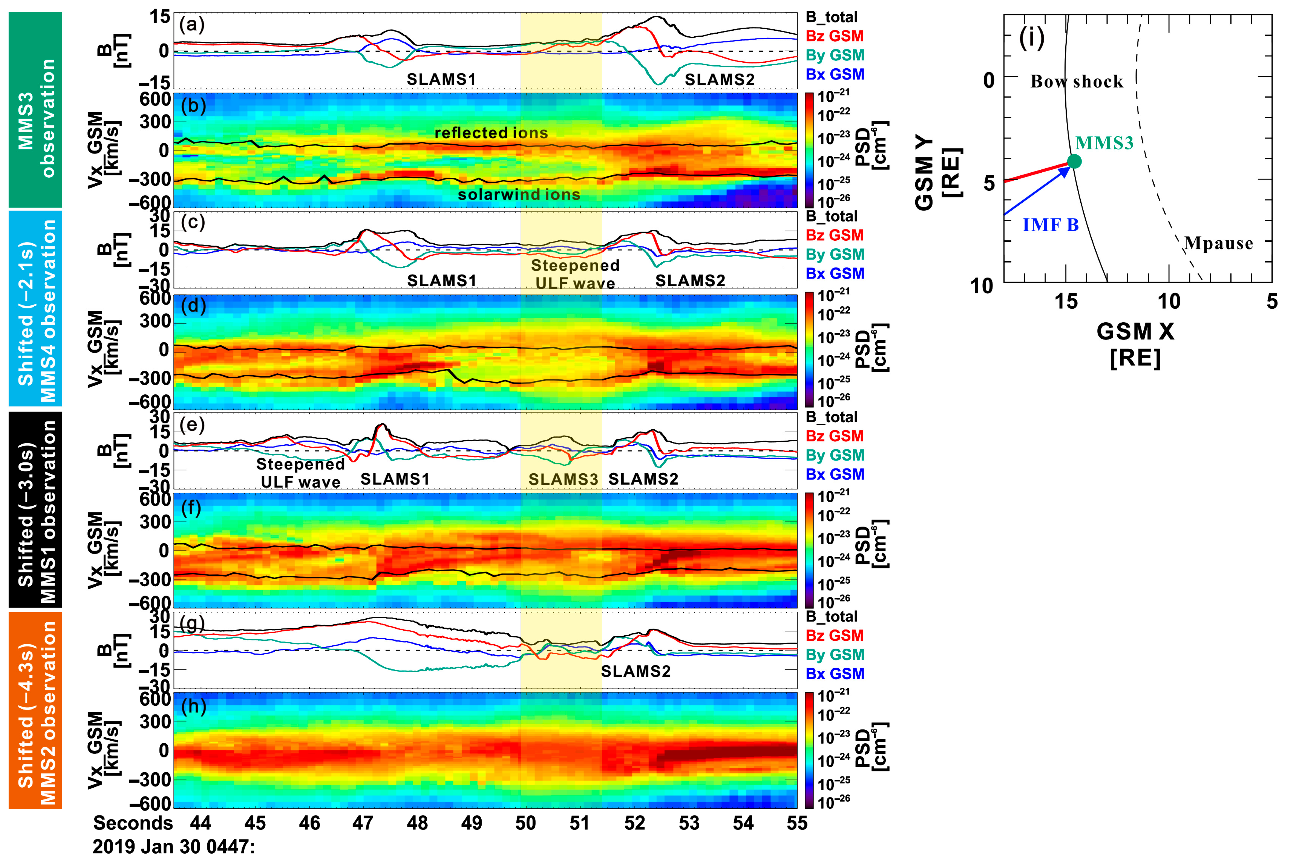
Figure 1. Magnetic field and reduced ion distribution as a function of Vx_GSM observed by (a,b) MMS3 (green bar on the left), (c,d) MMS4 (cyan bar on the left), (e,f), MMS1 (black bar on the left), and (g,h) MMS2 (orange bar on the left). The bulk velocity of the solar wind and reflected ions (black lines) are overlaid on the reduced ion distribution in (b,d,f). X/Y/Z component in GSM coordinate system is represented by blue/green/red curve. Burst-mode observation of MMS1, MMS2, and MMS4 are time-shifted to MMS3. The time interval of the SLAMSs evolution is highlighted by yellow shaded region. (i) The position of MMS3 (green dots), the interplanetary magnetic field (blue arrow), the normal direction of the bow shock (red line), bow shock (solid curve), and magnetopause (dashed line) obtained from the models [48] are shown in the GSM X-Y plane.
Magnetochemistry 10 00054 g001
Figure 2. (a) The magnitude of magnetic field observed by MMS1 (black curve), MMS2 (orange curve), MMS3 (green curve), and MMS4 (cyan curve); plasma density (red/black/blue curves for reflected ion/ion/electron, electron data of MMS4 are not available) and wavelet power spectra of the magnetic fields observed by (b,c) MMS3, (d,e) MMS4, (f,g), MMS1, and (h,i) MMS2. Burst-mode observation of MMS1, MMS2, and MMS4 are time-shifted to MMS3. The horizontal black and white dashed lines in wavelet power spectra indicate the fmax and the lower-hybrid frequency flh. The black bars on the top of (a) indicate the interval of magnetic reconnection. The hodogram of the magnetic field in the L-M plane observed by (j) MMS3, (k) MMS4, and (l) MMS1. The start and end points in (j,k) are marked by blue and red dots, respectively. The MMS3/4/1/2 observation are marked by green/cyan/black/orange bars in the left and (j,k).
Magnetochemistry 10 00054 g002
Figure 3. The ion distribution (in unit of s-3 cm-6) in the plane parallel to the magnetic field during the time interval of SLAMS3 observed by (a) MMS3, (c) MMS 4, and (e) MMS1 and the corresponding bi-Maxwellian fitting in (b,d,f). The solar wind ions and reflected ions are marked by magenta text in (b,d,f). The sun direction is marked by the magenta lines.
Magnetochemistry 10 00054 g003
Figure 4. Dispersion relation using model parameters by fitting the ion distribution of MMS3. Real frequency (solid curve) and growth rate (dashed curve) of the ion-ion non-resonant mode. The orange in diamond marks the real frequency and the wave number for MMS observations.
Magnetochemistry 10 00054 g004
Figure 5. MMS1 observation of current sheets in the LMN coordinate system between SLAMS 3 and SLAMS 2 (left panels)/inside SLAMS 2 (right panels): (a) electron density, (b) electron temperature, red/blue curves for parallel/perpendicular temperature (c) magnetic field, (d) electron (solid curve) and ion (dashed curve) velocity, (e) current density obtained from the FPI observation, (f) electric field, and (g) the energy dissipation of perpendicular (blue curves) and parallel components (red curves) and the sum of J∙E’. L/M/N components are represented by red/blue/black curves. The detailed information of L-M-N coordinates in GSM coordinates are shown on the top of this figure. The ion inertial length is indicated by green bars in (c).
Magnetochemistry 10 00054 g005
Table 1. Drift bi-Maxwellian fitting parameters and the saturation amplitude of the ion-ion non-resonate mode.
SatelliteIonDensity
(1/cm−3)
Vth‖
(km/s)
Vthꓕ
(km/s)
Vdrift‖
(km/s)
Vdriftꓕ
(km/s)
δB/B0 from MMSδB/B0
MMS 3Solar wind ions (SW)0.73050200190/0.93
Reflected ions (rf)0.212040100−20
Background ions0.02202020−20
MMS 4Solar wind ions0.77040−2001801.791.84
Reflected ions1.2801208080
Background ions0.13030400
MMS 1Solar wind ions0.76040−160102.813.21
Reflected ions1.2125100−25175
Background ions0.12252520−25
2.5175120−10510
Disclaimer/Publisher’s Note: The statements, opinions and data contained in all publications are solely those of the individual author(s) and contributor(s) and not of MDPI and/or the editor(s). MDPI and/or the editor(s) disclaim responsibility for any injury to people or property resulting from any ideas, methods, instructions or products referred to in the content.