Abstract
In recent years, researchers have been making a persistent effort to discover innovative and appropriate oxide materials that can be exploited in optoelectronics devices. The primary objective of this research is to study the effect of Na/Mg co-doping on microstructure, transport (dielectric and Hall Effect), optical and magnetic properties of Ti0.94-yNa0.06MgyO2 (y = 0–0.08) compounds that were synthesized using a solid-state route method. All the compounds have been crystallized to a single rutile phase, as reported by the XRD study. The elemental color mapping reveals that there is a consistent distribution of all of the elements across the compound. The XPS study suggests that Ti mostly resided in the Ti4+ oxidation state. The enhancement of the Mg co-doping concentration led to a decrease in the dielectric value as well as the AC conductivity of the material. In addition to this, it has been noted that these compounds have a low dielectric loss. The analyses of Nyquist plots reveal that the increase of Mg co-doping concentration led to a rise in the amount of relaxation that is non-Debye sort. This, in turn, caused a reduction in the amount of resistance exhibited by grains and grain boundaries. The Maxwell–Wagner model was used to conduct an analysis of the dielectric data, and the results indicated that the hopping of charge carriers is most likely to be responsible for the transport of electrical charges. From the optical properties’ measurement and analyses, it was noticed that the band gap had been slightly changed, but the transmittance value had increased from 81% for Ti0.94Na0.06O2 to 84% with an increase in Mg co-doping concentration. The Hall Effect analysis unequivocally pointed to the presence of p-type conductivity as well as an increased carrier density concentration. The room temperature magnetization versus field measurement indicates the ferromagnetic nature of the samples. Thus, the co-doping of Mg with Na in TiO2 leads to a narrowing of the band gap of TiO2 while tweaking the optical and transport properties. The studied materials can be utilized for spintronics and optoelectronics applications.
1. Introduction
Researchers have devoted a great deal of time and effort over the past few decades to finding novel materials that can be incorporated into optoelectronic and spintronic systems. Devices like this allow for lower power consumption, faster data processing, non-volatility, and higher storage densities at temperatures higher than room temperature [1,2]. Transition metal (TM)-doped semiconducting oxides have been studied more than any other class of material for their potential use in optoelectronics and spintronic devices. Excellent optical properties and room-temperature ferromagnetism (RTFM) have been discovered in TM-doped semiconducting oxides such as SnO2, ZnO, TiO2, and ZrO2 [3,4,5,6,7,8,9,10,11,12,13], which have been studied by a number of laboratories. Moreover, non-magnetic element-doped oxide materials (viz., SnO2, TiO2, ZnO, LaO3) were also found to exhibit excellent optical, transport, and magnetic properties suggested by a number of ab-initio calculations [14,15,16,17,18,19,20,21,22,23,24,25,26,27,28] and experimental studies [29,30,31,32,33,34,35,36,37,38,39,40,41,42,43].
TiO2, in particular, has received a lot of focus in the past decade from the field of materials science, alongside other oxides. The three crystalline forms of TiO2 are called anatase, rutile, and brookite. The crystalline form, rutile, of natural titanium dioxide is very common. Rutile TiO2 is classified as a tetragonal material with a space group of P42/mnm. Because of its high stability, low cost, lack of toxicity, and exceptional electrical, magnetic, and optical properties, it is being considered for a wide range of uses [41]. The structural, optical, magnetic, and dielectric properties of TiO2 are sensitive to a wide range of parameters, such as dopant type and purity, growing circumstances, and environmental influences. Doping TiO2 with a transition metal or a nonmetal can alter its band edge and surface states [12,13]. When the doped element is included in the TiO2 crystal lattice, new energy levels may be generated between the valence band and the conduction band. Because of the ease with which an outer shell electron can be provided, alkali metals, including calcium, sodium, magnesium, and lithium, are preferred as dopants for TiO2. The possibility of d0 ferromagnetism in TiO2 by doping with non-magnetic elements has been explored both theoretically and experimentally extensively by researchers. Experimental studies suggest that TiO2 will exhibit RTFM after being doped with non-magnetic elements like K [24], Mg [26], Cu [28,29], and noble metals like Ag [27]. Recent research has shown that introducing Na dopants into TiO2 results in a number of exciting new properties, including enhanced conductivity, zero dielectric loss, and room-temperature ferromagnetism [44]. Thus, the obtained results in TiO2 reveal several intriguing pieces of information which can be useful in spintronics and optoelectronics applications. In this study, we focused on Na/Mg co-doped rutile TiO2 compounds and analyzed their optical, transport, and magnetic properties. Mg is used as the co-dopant in our investigation because of its identical ionic radii with Ti which helps to stabilize the crystal structure while tweaking the other physical properties. To improve the precision of our characterizations and lessen the frequency of fabrication errors, we synthesized these compounds utilizing a traditional solid-state approach in bulk formation.
2. Experimental Details
We used the standard solid-state reaction technique to synthesize Ti0.94-yNa0.06MgyO2 (where y = 0, 0.02, 0.04, 0.06, and 0.08) polycrystalline samples. Alfa Aesar’s supplied TiO2 (99.95%), Na2CO3.H2O (99.997%), and MgO (99.95%) were used as raw materials. After the stoichiometric values were determined, the compounds were individually weighed with a digital balance (Model No. BSA323S-CW, Sartorius, Germany). Initially, we used a mortar and pestle to crush and blend the first batch of ingredients, and then we added acetone to verify consistency. After pre-sintering the powdered mixture for 10 h at 300 °C, it was sintered for 20 h at 500 °C and 800 °C. The density of the pelletized samples was increased using a 10-h annealing process at 1000 and 1200 °C. To determine the crystalline phase, a Bruker diffractometer was used to record XRD patterns. Microstructures of the materials were captured by means of a field emission scanning electron microscope (FESEM, Model Sigma, Manufacturer Zeiss). The elemental and color mapping research was carried out with the aid of an energy-dispersive spectrophotometer and a Field Emission Scanning Electron Microscope. Oxidation states of elements in the samples were determined using X-Ray Photoelectron Spectroscopy (Make: Physical Electronics (PHI)& Model: PHI 5000 VersaProbe III), which utilized a highly focused monochromatic X-ray beam of <10 μm to 300 μm. To collect the optical absorption spectra, a Shimadzu UV-VIS spectrophotometer (model number UV-2600) was used. The experiments were carried out between 300 and 800 nm. At room temperature, we measured the dielectric constant, dielectric loss, impedance, and AC conductivity. In each test, frequencies between 100 Hz and 5 MHz were applied. The pellet was given a coating of silver paste that would conduct electricity and then placed in a sample container that was connected to an impedance tester. Finally, the pellet was placed in the sample container of the dielectric measurement system (Model: PSM-1735; 4NL-LC, Loughborough, UK). To count and quantify charge carriers, hall effect measurements were performed in a Van der Pauw setup at room temperature. A commercial SQUID Quantum Design magnetometer (Model: VersaLab, MPMS XL, San Diego, CA, USA) was utilized to capture the M-H hysteresis loop responses.
3. Results and Discussions
The formation of the crystalline phase of these prepared materials was identified through the structural study by recording XRD patterns. The detailed crystal structure study is reported elsewhere [44]. The analyses of the XRD patterns indicate that the materials have been formed in a tetragonal rutile-type crystal structure of TiO2. The typical cell parameters of Ti0.94Na0.06O2 are estimated to be a = b = 4.5917 Å and c = 2.9585 Å. The mean crystallite sizes (Sc) of all the synthesized polycrystalline compounds were estimated to be in the range of 60–80 nm.
3.1. Microstructure Study by SEM and Compositional Study by EDS
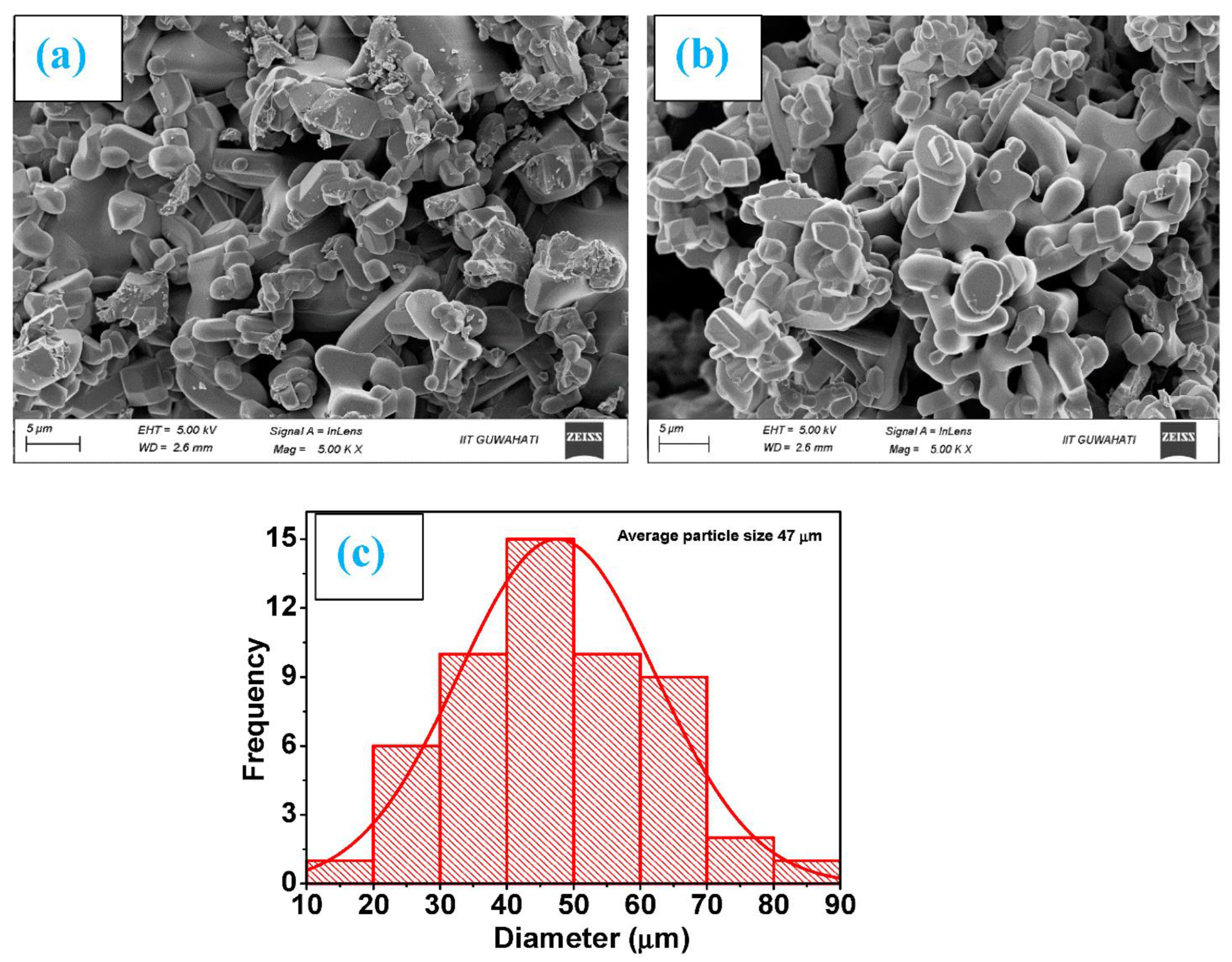
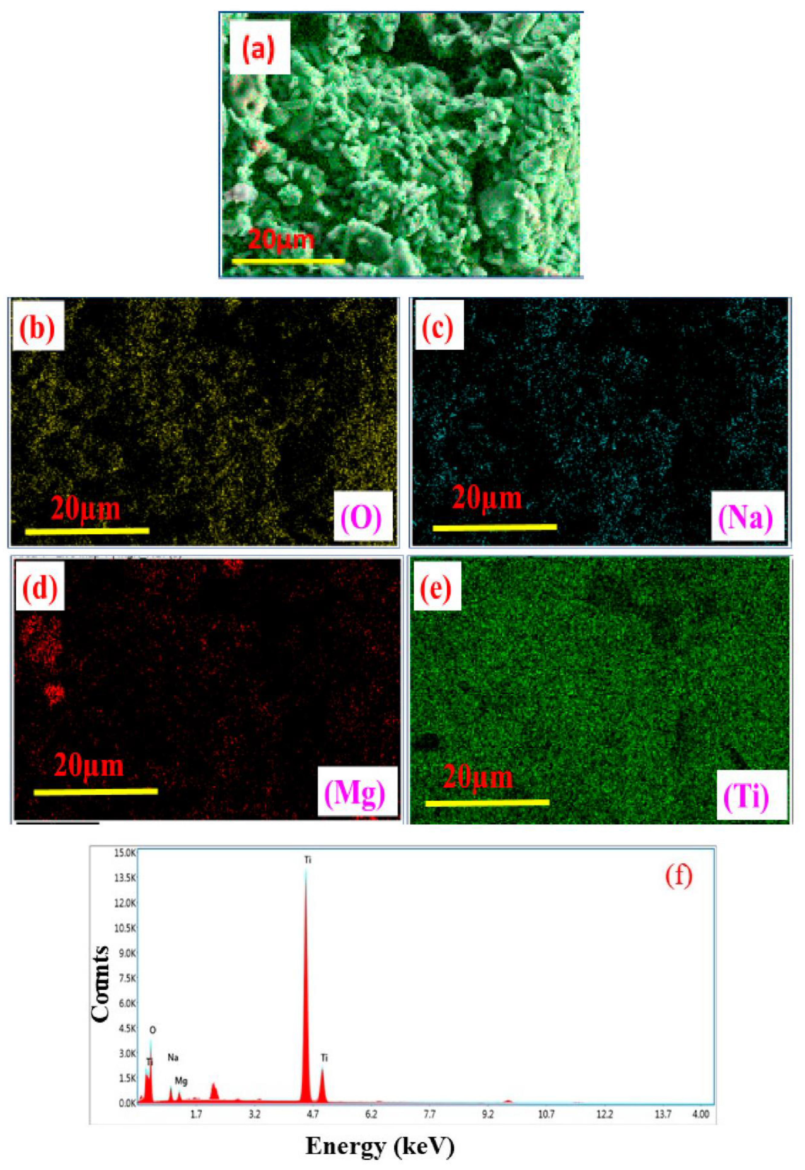
High-resolution FE-SEM was used to conduct the microstructural investigation of the samples. The typical SEM micrographs of Ti0.90Na0.06Mg0.04O2 and Ti0.86Na0.06Mg0.08O2 are illustrated in Figure 1a,b, respectively. As observed from the SEM micrographs, the morphology of all Na/Mg co-doped compounds is homogenous. The particles in the compound have an approximately circular form, and they are nanoscale in size. Through the use of the Image J program and a Gaussian fitting of the particle size distribution acquired from several SEM micrographs, the particle size was determined and subsequently estimated. The average particle size was somewhere in the region of 20 to 70 μm for these compounds. The Gaussian fitting for Ti0.86Na0.06Mg0.08O2 is demonstrated in Figure 1c, and the particle size is determined to be 47 μm according to the graph. It was feasible to deduce the elemental composition and distribution of materials observed in scanning electron microscopy by employing color mapping derived from the EDS spectrum. Figure 2a depicts an example of a combined elemental color mapping for the Ti0.90Na0.06Mg0.04O2 compound, whereas Figure 2b–e shows the color mappings for each of the four individual constituent elements individually. Compounds containing all elements are shown to be evenly distributed by the color mapping of the elemental distribution. Table 1 shows the atomic percentage of elements experimentally observed from EDS for Ti0.94-yNa0.06MgyO2 for y = 0, 0.02, 0.04, 0.06, and 0.08 compounds. Moreover, the final synthesized compounds have no unwanted detectable magnetic impurities like Co or Fe, as shown by EDS analysis. The elemental composition is also very similar to the nominal concentration of the sample under study.
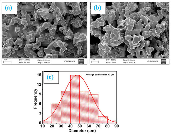
Figure 1.
Morphology images as measured by SEM for (a) Ti0.90Na0.06Mg0.04O2 and (b) Ti0.86Na0.06Mg0.08O2 compounds and (c) the fitting of a Gaussian function to the particle size distribution of Ti0.86Na0.06Mg0.08O2 compound.
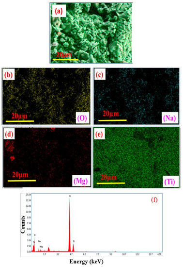
Figure 2.
(a) Elemental color mapping of Ti0.90Na0.06Mg0.04O2 compound; (b–e) correspondingly exhibit the individual color mappings for the elements O, Na, Mg, and Ti; and (f) EDAX spectrum of Ti0.90Na0.06Mg0.04O2 compound.

Table 1.
Estimated cationic ratio of elements present in Ti0.94-yNa0.06MgyO2 (y = 0, 0.02, 0.04, 0.06, and 0.08) compounds as measured by energy dispersive spectroscopy (EDS).
3.2. X-ray Photoelectron Spectroscopy (XPS)
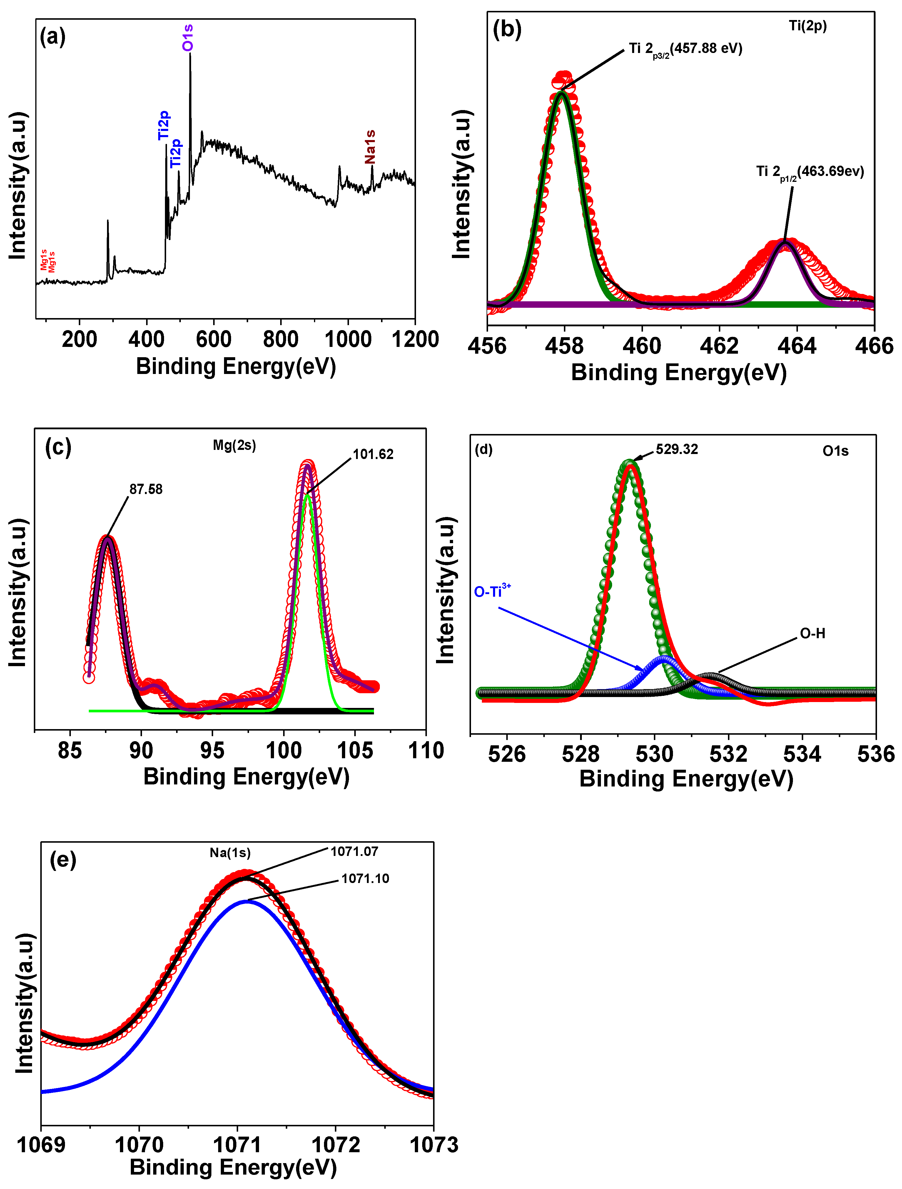
The X-ray photoelectron spectroscopy (XPS) method is a sensitive surface analysis technique that may be used to effectively probe the surface composition and chemical states of solid samples. The oxidation state and surface chemical composition of Na/Mg co-doped TiO2 compounds were measured by XPS. Images of the X-ray photoelectron spectroscopy (XPS) of a sample of Ti0.88Na0.06Mg0.06O2 are displayed in Figure 3. Most of the C1s peak at 284.6 eV is a direct result of atmospheric pollution. Titanium, oxygen, magnesium, and sodium can all be seen in the XPS spectrum shown in Figure 3a, suggesting that they are all present at the surface. The binding energies of Ti 2p3/2 and Ti 2p1/2 were measured to be at 457.88 and 463.69 eV, respectively, as shown in Figure 3b, suggesting that Ti mostly resided in the Ti4+ oxidation state [25]. Figure 3d displays XPS spectra of the O 1s area. Three peaks, with binding energies of about 529.32 eV, 530.23 eV, and 531.47 eV, can be used to fit the O 1s spectra, which corresponds to lattice oxygen in TiO2 oxygen in Ti2O3 (O-Ti3+/Ti4+) and hydroxyl group (-OH) oxygen, respectively. It is shown in Figure 3c the XPS spectra of the Mg 2s area. Two binding energy peaks, at 87.58 eV and 101.62 eV, are visible in the spectra of the Mg 2s. These two Gaussian peaks, at 87.58 and 101.62 eV, respectively, reflect Mg2+ ions occupying octahedral and tetrahedral positions in the Mg 2s peak. Na 1s XPS spectra are displayed in Figure 3e. Specifically, Na 1s has a binding energy maximum of 1071.07 eV.
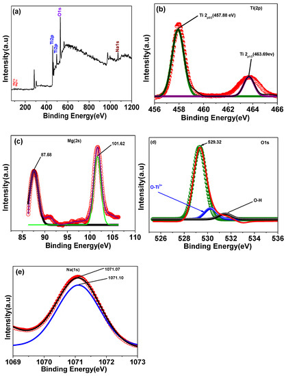
Figure 3.
XPS spectra of (a)Ti0.88Na0.06Mg0.06O2 compound, (b) Ti 2p peak, (c) Mg 2s peak, (d) O 1s peak, and (e) Na 1s peak of Ti0.88Na0.06Mg0.06O2 compound, respectively.
3.3. Dielectric Constant (εr), Loss Tangent (tanδ), Complex Impedance, and AC Conductivity
3.3.1. Dielectric Constant (εr)
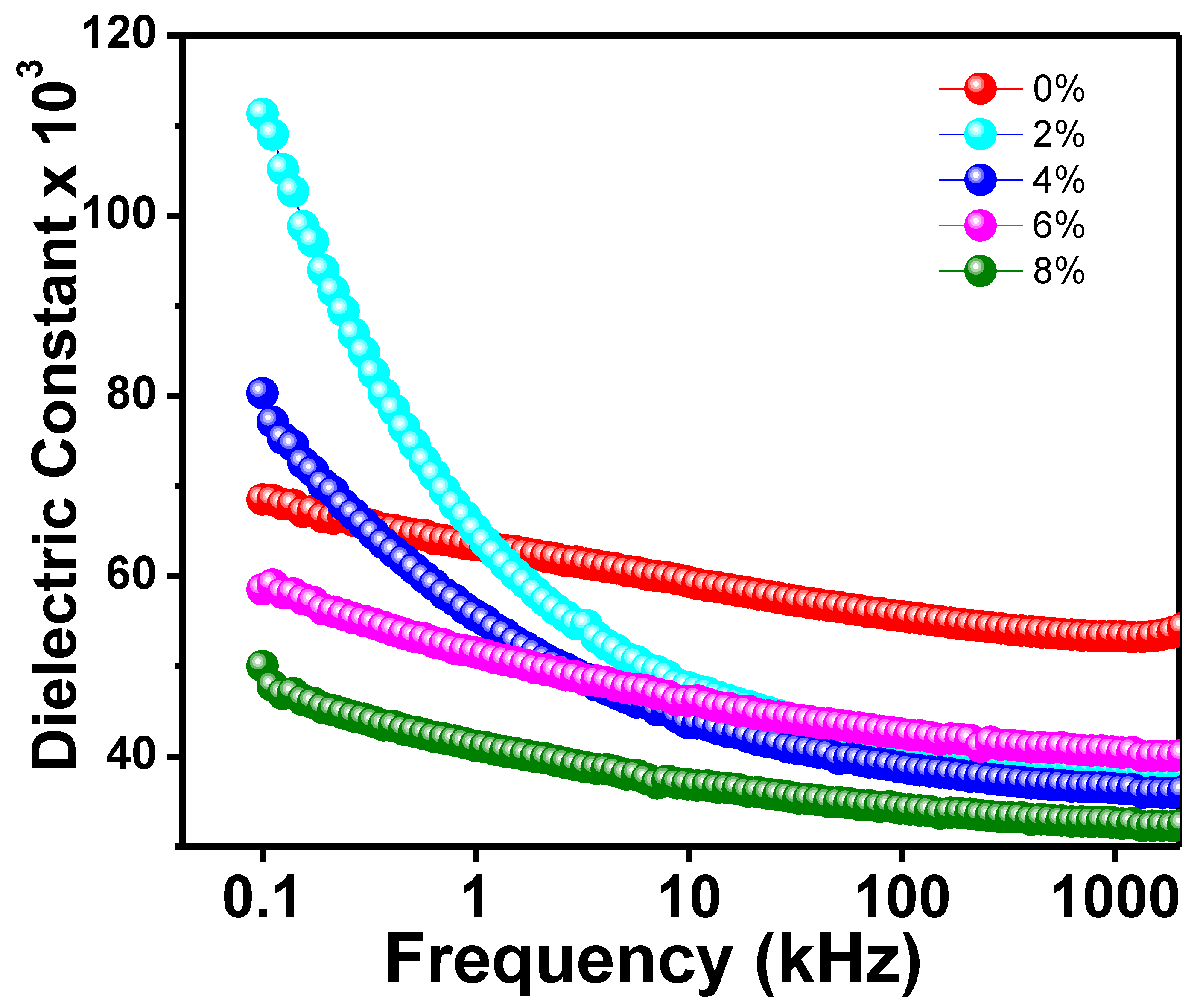
Figure 4 depicts the frequency-dependent dielectric constant (𝜀r) for all Na/Mg co-doped TiO2 compounds. The initial 𝜀r value of all substances has been observed to decrease with increasing frequency. At higher frequencies, however, a flat response curve is observed, which suggests that the 𝜀r value does not change drastically. Because of this, it is possible that each of the new compounds will show some degree of dielectric dispersion. Dielectric constant readings are large at low frequencies and decrease with increasing frequency, indicating a dielectric transition in the sample. Further, the dielectric constant is largest at low frequencies and decreases with increasing frequency. The interfacial polarisation, dipolar polarisation, ionic polarisation, and electronic polarisation that make up the total polarisation are what we need to discuss in order to understand what’s behind the observed dielectric behavior shift in the sample [45]. When an external AC electric field is applied, and all-electric dipoles are aligned in that direction of the field, the dielectric constant is at its maximum value at low frequencies. However, the contribution of ionic and dipolar polarisation to the total polarisation computation decreases as the frequency increases because relatively heavy particles become unable to follow the applied electric field. However, at higher frequencies, the contribution of grain boundaries becomes more noticeable as a result of the accumulation of defects such as impurities and deficiencies as well as thermally activated charge carriers, which together increase the value of interfacial polarisation first introduced by Maxwell–Wagner [45]. Their proposed model included a grain boundary layer and a layer of well-conducting grains. At high frequencies, electron activity increases at grain boundaries, while at low frequencies, it decreases. This indicates that the grain boundaries are a very resistant region. Dielectric loss is minimized as a result since the dielectric constant has the smallest value at higher frequencies.
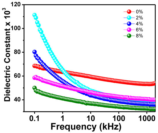
Figure 4.
The frequency variation of dielectric constant of Ti0.94-yNa0.06MgyO2 with y = 0, 0.02, 0.04, 0.06, and 0.08 compounds.
3.3.2. Dielectric Loss
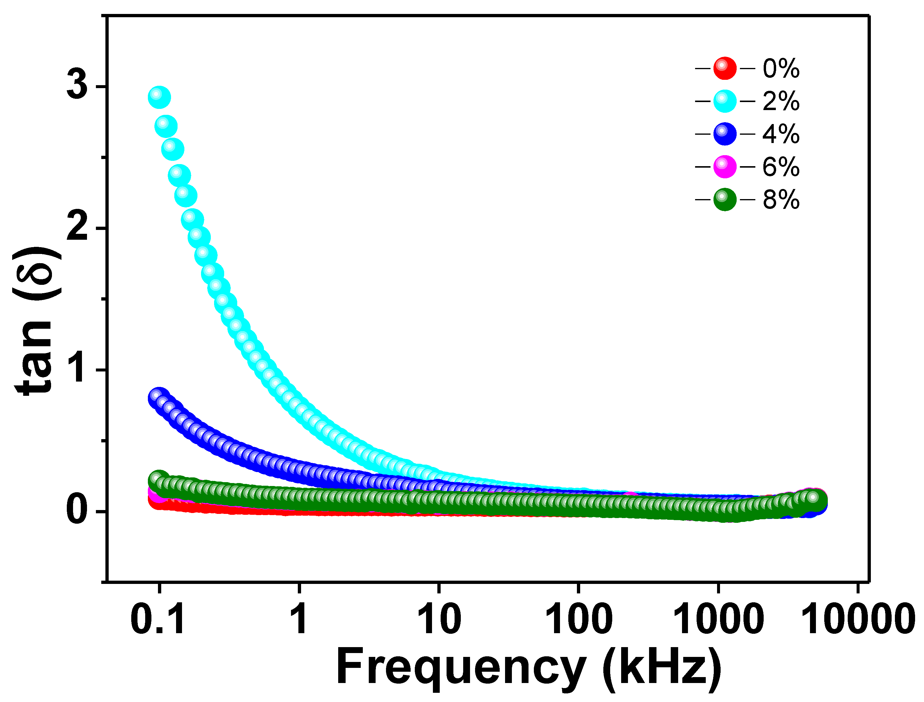
Figure 5 depicts the variation of loss tangent (tanδ) with applied AC frequency for all Na/Mg co-doped TiO2compounds. As can be observed from the graph, the value of the dielectric loss drops by a significant amount as the alternating current frequency is increased. On the other hand, the value of tanδ remains essentially constant as it gets closer and closer to zero as the frequency increases. The Maxwell–Wagner model combined with Koop’s theory can provide a satisfactory explanation for this fluctuation in the loss tangent value with increasing frequency [45]. At lower frequencies, the concentration of charge carriers keeps on rising as a result of the extraordinarily active nature of the insulating grain boundaries. As a consequence of this fact, a greater amount of energy is required to transport the charge carriers through the grain boundaries, which eventually results in a greater degree of dielectric loss. Charge carriers are able to flow easily at the grains because semiconducting grains are more active at higher frequencies. Despite the fact that the frequency is greater, there is not a significant loss of energy as a result of this free flow of charge carriers. This leads to a smaller dielectric loss. In addition, within the specified frequency range, none of the curves that we generated for our studies exhibited any kind of loss peak. One possible explanation for the absence of a peak is that the dielectric permittivity makes only a small contribution to any frequency-dependent changes in the dielectric loss. Because there was no dielectric loss in the samples that were prepared, it is clear that these materials have the potential to be utilized in high-frequency optoelectronic devices.
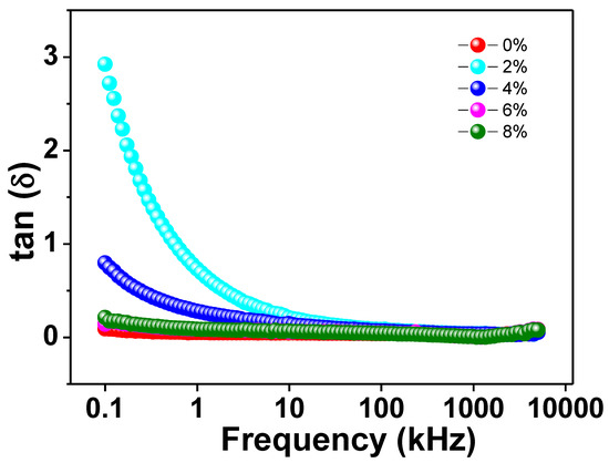
Figure 5.
The frequency variation of tangent loss of Ti0.94-yNa0.06MgyO2 with y = 0, 0.02, 0.04, 0.06, and 0.08 compounds.
3.3.3. Complex Impedance Analysis (CIA)
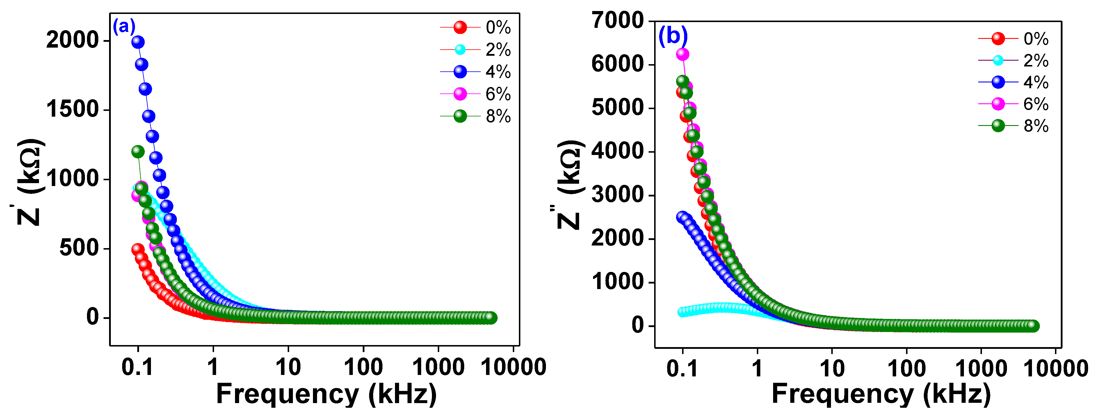
The frequency dependence of the real and imaginary parts of the alternating current impedance (Z′ and Z″) is depicted in Figure 6a,b, respectivelyfor Ti0.94-yNa0.06MgyO2 where y = 0, 0.02, 0.04, 0.06, and 0.08. The plots show that as frequency increases, Z′ decreases consistently up to a limiting range of roughly 10 kHz and then almost stops depending on the frequency at higher frequencies. The material is shown to have both linear and circular polarisation in this way. However, at lower frequencies, a larger value of Z′ is seen, suggesting that the materials are highly polarised. Z″, the imaginary part of the impedance, exhibits a similar pattern of variation, contingent upon the frequency being employed. The graph clearly shows that as Na/Mg co-doping levels in TiO2 rise, the imaginary component of the overall impedance falls, and the peak frequency moves down the spectrum. The conductivity increases as the imaginary part of the impedance decreases, and the peak shifts, indicating that Mg co-doping grows as the material relaxes. The decrease in the imaginary part of the impedance with increasing Mg co-doping reflects the increased accessibility of the charge carriers to the alternating current electric field.
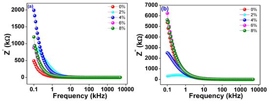
Figure 6.
(a) The frequency variation of real part of ac impedance Z′. (b) The frequency variation of imaginary part of AC impedance Z″ of Ti0.94-yNa0.06MgyO2 with y = 0, 0.02, 0.04, 0.06, 0.08 compounds.
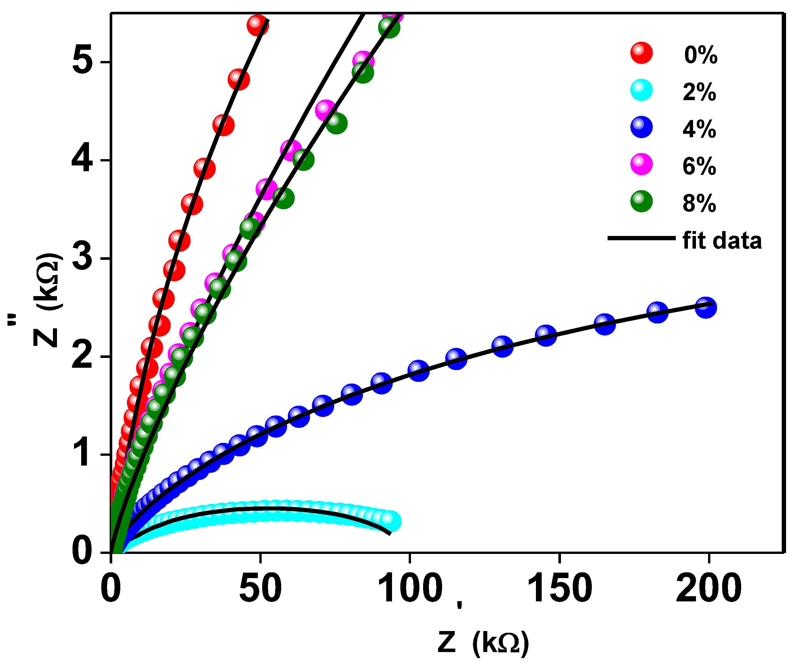
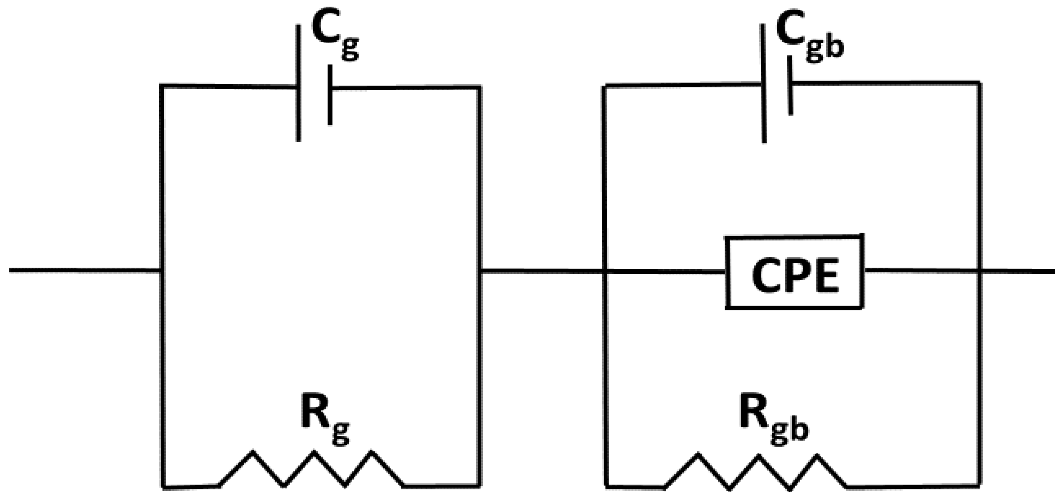
Complex impedance analysis (CIA), which makes use of Nyquist plots, can be helpful for understanding the effects of grains, grain boundaries, and likely electrode effects on the capacitive, reactive, resistive, and inductive properties of the materials. This research allows us to disentangle the roles played by grains and grain borders in the overall impedance of the material. The Nyquist pattern for compounds with y = 0, 0.02, 0.04, 0.06, and 0.08 of Ti0.94-yNa0.06MgyO2 at room temperature is shown in Figure 7. It shows that the resistance of Ti0.94-yNa0.06MgyO2 compounds has grown gradually as the Mg concentration is reduced, as evidenced by a narrower semicircle in the Nyquist plot. This resistance value has a substantial effect on the real and imaginary parts of the impedance’s amplitude. When fitting the Nyquist plot, it is necessary to select a suitable comparable circuit model. The electrical properties of the material are described by a series-connected two-leg equivalent circuit. These branches are meant to depict the electrical properties of the material at the grain boundaries as well as within the grains themselves. By employing the ZSimpWin application, one may display the properties of each component of the comparable circuit depicted in Figure 8.
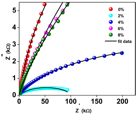
Figure 7.
The Nyquist Plot of Ti0.94-yNa0.06MgyO2 with y = 0, 0.02, 0.04, 0.06, 0.08 compounds.
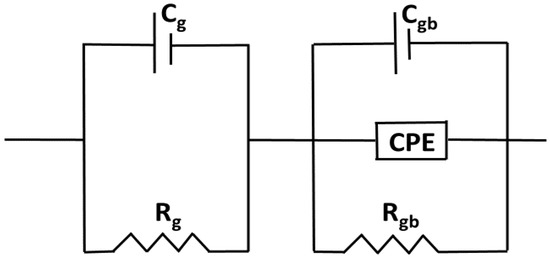
Figure 8.
The Equivalent circuit model for Nyquist Plot of Ti0.94-yNa0.06MgyO2 with y = 0, 0.02, 0.04, 0.06, 0.08 compounds.
To separate the effects of grains from those of grain boundaries, we employed a series combination of two parallel circuits. Rg and Cg, which stand for the grain resistance and capacitance, respectively, are connected in series in the first parallel circuit. In the second parallel circuit, Rgb, Cgb, and CPE stand for the grain boundary resistance, grain boundary capacitance, and constant phase element, respectively. The factors taken into account while modeling analogous circuits are tabulated in Table 2. Evidence suggests that Rg and Rgb both decline with increasing co-doping concentration, which points to a general decrease in R across the boundary in the samples. It can be inferred from the decreasing Rg and Rgb numbers. The high R effects on carrier flow between the metal and the semiconductor could be a contributing factor. The interface between metal and semiconductor may be rough or have a lattice mismatch, which would have the same effect [46,47].

Table 2.
Equivalent circuit parameters of the complex impedance plots of Ti0.94-yNa0.06MgyO2 for y= 0, 0.02, 0.04, 0.06, and 0.08.
3.3.4. AC Conductivity
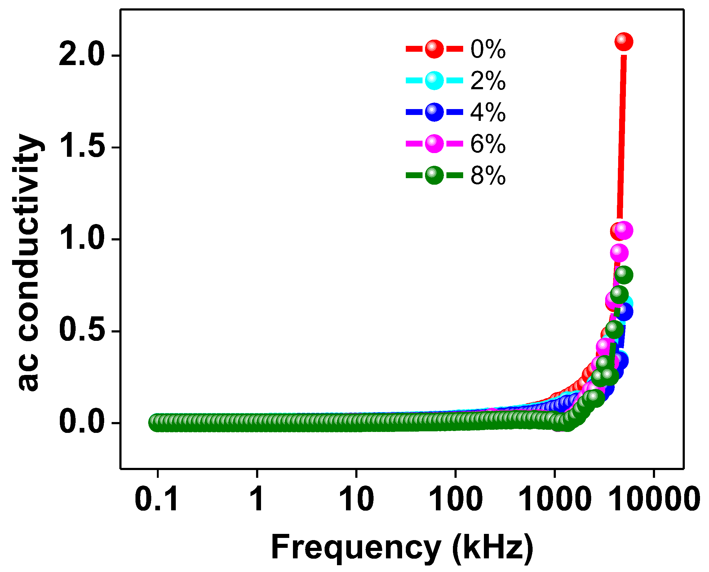
Figure 9 graphically depicts the correlation between the applied frequency and the AC conductivity of every Na/Mg co-doped TiO2 compound. The AC conductivity is nearly constant as a function of frequency up to 102 Hz, but then the figure shows a distinct increase in conductivity. This data indicates that increasing the Mg co-doping concentration in the TiO2 compound will enhance the material’s AC conductivity at higher frequencies. It has been suggested that the hopping model [45] can provide an explanation for the observed pattern of behavior in AC conductivity. At low frequencies, transport occurs along a virtually infinite channel, resulting in an extremely low value for AC conductivity. As a consequence, the rate at which they hop is reduced. It has been found that increasing the frequency of the alternating current flowing through a material increases the pace at which charge carriers hop. This results in an increase in the AC conductivity of the material due to an increase in the hopping of charge carriers.
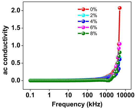
Figure 9.
The frequency variation of AC conductivity of Ti0.94-yNa0.06MgyO2 with y = 0, 0.02, 0.04, 0.06, 0.08 compounds.
3.4. Hall Effect Measurement
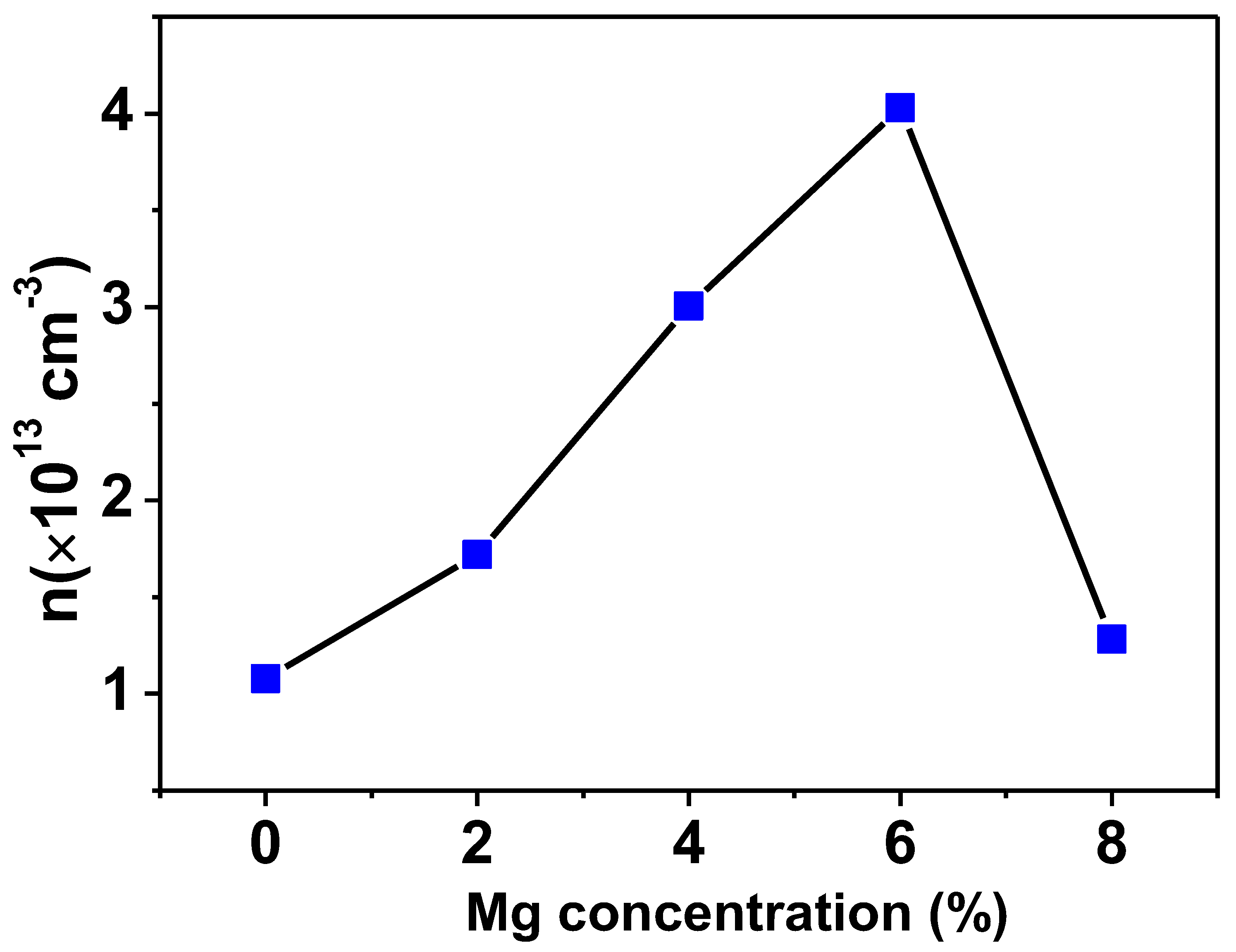
For the purpose of determining the carrier density and the kind of doping present in Ti0.94-yNa0.06MgyO2 with y = 0, 0.02, 0.04, 0.06, 0.08 compounds, a Van der Pauw configuration was utilized for the Hall effect measurement. According to the findings of this investigation, the conductivity of all Na/Mg co-doped TiO2 compounds is p-type. Hole density (also called carrier density) increases with Mg concentration, as shown in Figure 10. The production of holes results from the substitution of Mg atoms for Ti atoms because Mg has a lower valency state than Ti ions. As a whole, the carrier density for all Na/Mg co-doped TiO2 compounds is estimated to range between 1–4 × 10¹³/cm3.
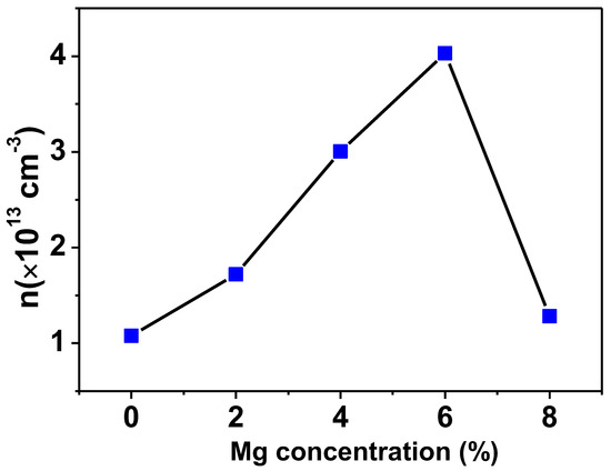
Figure 10.
Variation of carrier density in TiO2 with Na/Mg co-doping concentrations.
3.5. Optical Properties
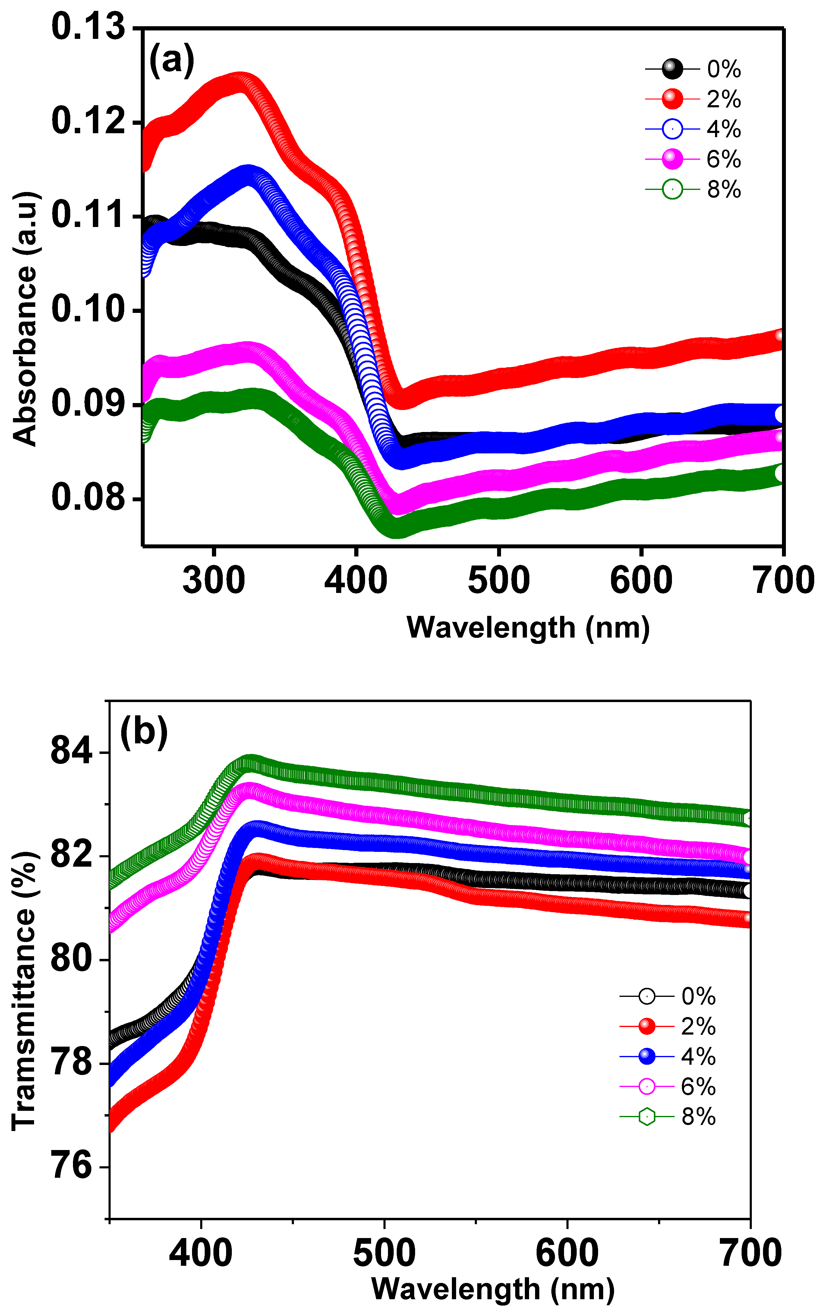
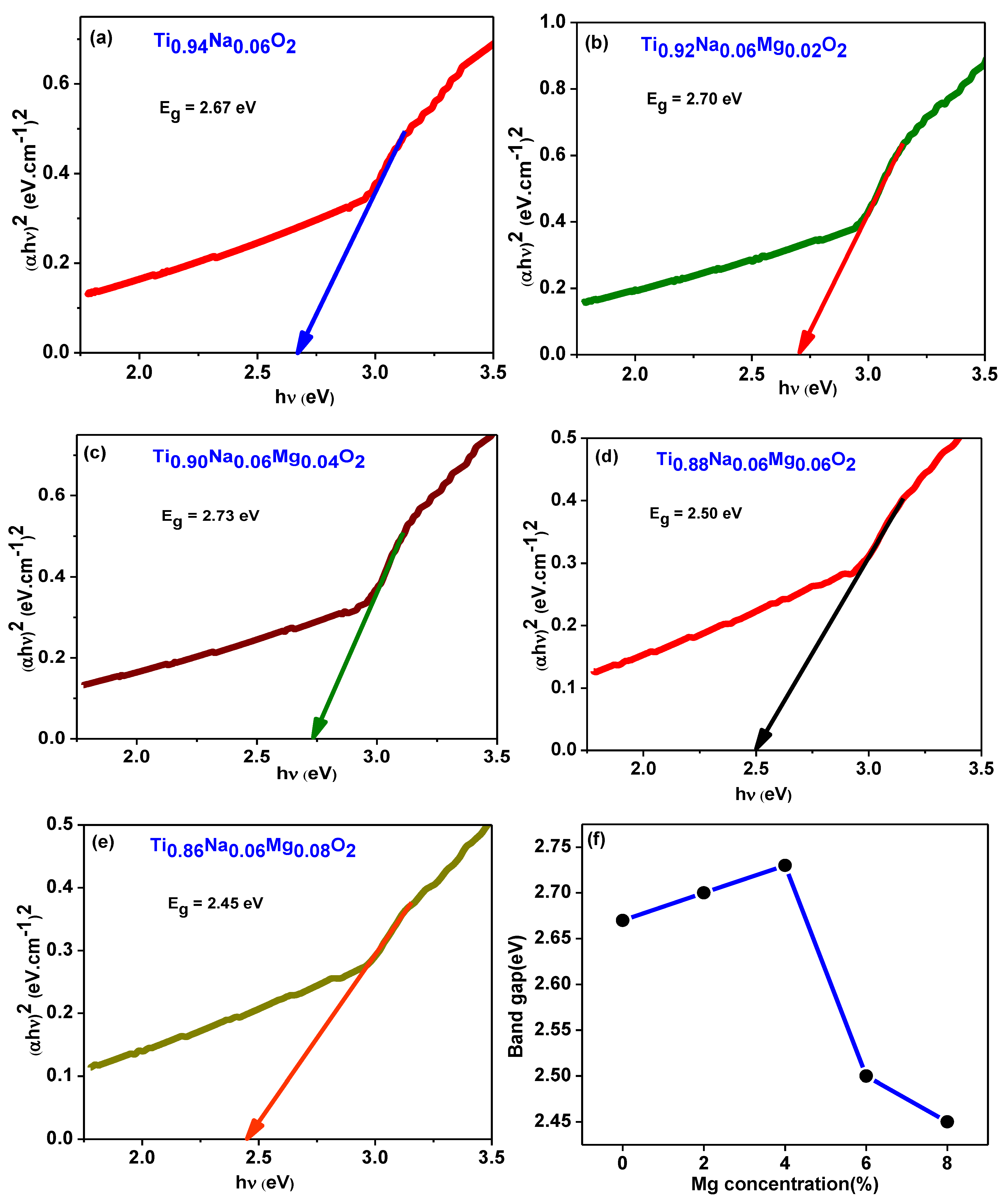
The optical absorbance spectra of Ti0.94-yNa0.06MgyO2 compounds with y = 0, 0.02, 0.04, 0.06, 0.08 were obtained by using a UV Visible spectrophotometer to collect data in the 300–700 nm wavelength region. The UV absorption edge in the Ti0.94Na0.06O2 compound’s absorption spectra can be seen at 350 nm, as illustrated in Figure 11a. This could be owing to TiO2’s inherent band gap absorption, which occurs as a result of electronic transitions from the valence band to the conduction band (O2pto Ti3d). The energy band gap of the materials is calculated using Tauc and Davis
Mott method for direct band gap semiconductors [48]. This formula was created for direct band gap semiconductors. In this equation, α represents the absorption coefficient, h the Planck constant, ν the photon frequency, and Eg the semiconductor’s optical band gap. Figure 10 illustrates a Tauc’s plot, which was constructed by graphing as a function of photon energy hν, which was collected from all of the samples’ absorption spectra. The values of band gap Eg are discovered at the place where the straight line on the x-axis of the Tauc plots makes an intercept. The band gap energy in Ti0.94Na0.06O2 is 2.67 eV, which is similar to the typical value discovered in a recent work [44]. The energy band gap for TiO2 compounds with 2%, 4%, 6%, and 8% Na/Mg co-doping is 2.70 eV, 2.73 eV, 2.50 eV, and 2.45 eV, as illustrated in Figure 12a–e, respectively. The fluctuation of the band gap in TiO2 with Na/Mg co-doping concentrations is shown in Figure 10f. As a result, calculating the band gap of Na/Mg co-doped TiO2 compounds shows that the band gap in TiO2 compounds decreases as the amount of Na/Mg co-doping increases. This extra decrease in the energy band gap of the TiO2 compound in the presence of Mg co-doping could be attributed to the formation of a thin impurity band inside the forbidden band gap area, increasing their value for optoelectronics. Figure 11b depicts the optical transmittance spectra of all Na/Mg co-doped TiO2 compounds. These spectra were collected across a wavelength range of 300–700 nm. For wavelengths ranging from 420 to 700 nanometers, the transmittance spectra exhibit transparent behavior. These materials, on the other hand, can block light with wavelengths shorter than 420 nm because of the presence of the TiO2 absorption edge at 350 nm. The presence of this edge may explain this phenomenon. Furthermore, as demonstrated in the spectra, the transmittance value increases with Mg content, increasing from 81% to 84% for 8%Na/Mg co-doped TiO2.
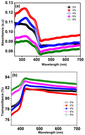
Figure 11.
(a) UV-Visible absorption spectra of Ti0.94-yNa0.06MgyO2 with y = 0, 0.02, 0.04, 0.06, 0.08 compounds and (b) UV-Visible transmittance spectra of Ti0.94-yNa0.06MgyO2 with y = 0, 0.02, 0.04, 0.06, 0.08 compounds.
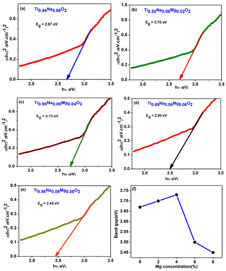
Figure 12.
(a–e) depict the Tauc’s plot generated from absorption spectra for Ti0.94-yNa0.06MgyO2 with y = 0, 0.02, 0.04, 0.06, 0.08 compounds. Figure (f) illustrates the fluctuation of the band gap in TiO2 with Na/Mg co-doping concentrations.
3.6. Magnetic Properties
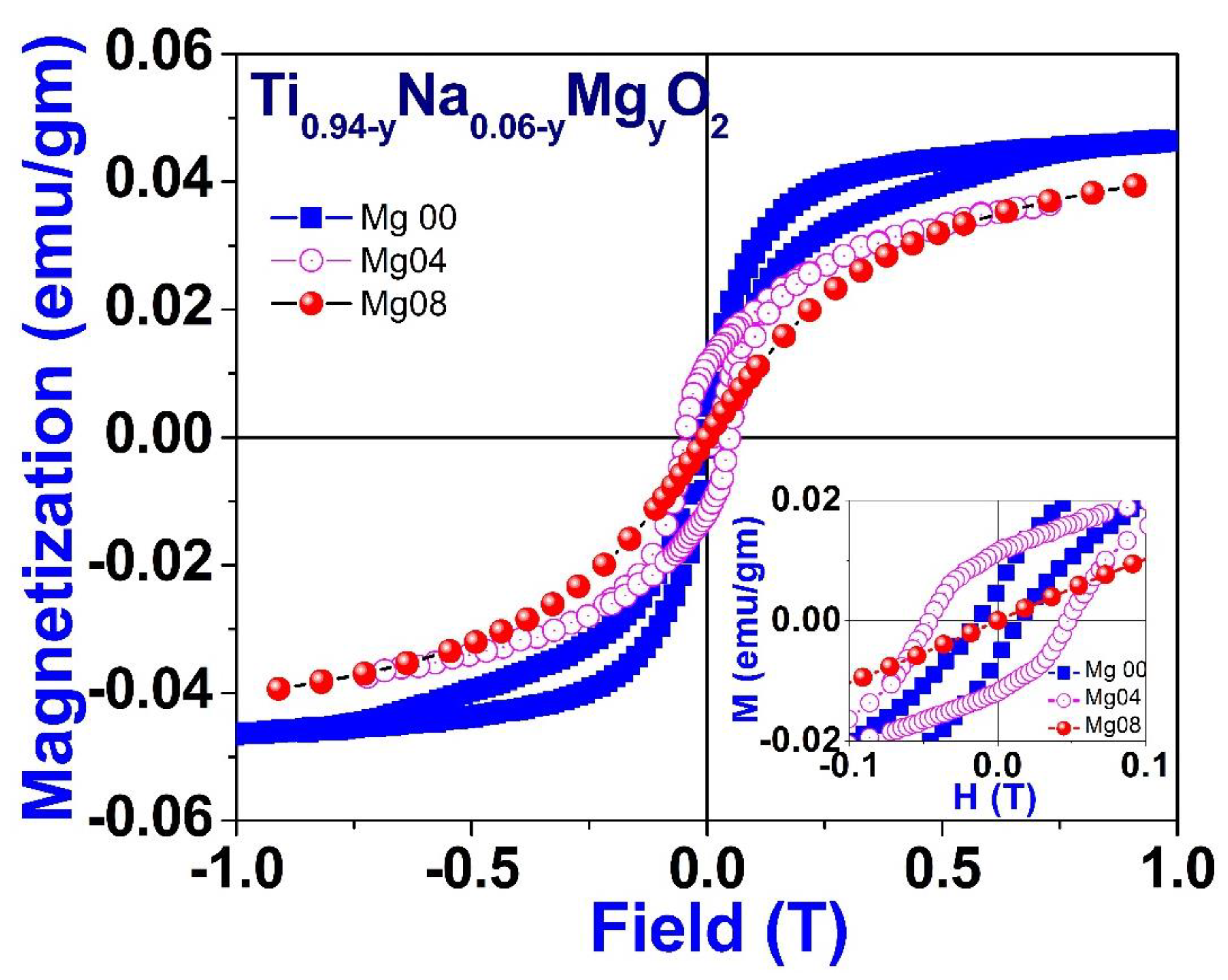
Figure 13 illustrates the field variation of magnetization measurements, also known as M-H curves, which were acquired at room temperature for a particular composition of Na/Mg co-doped TiO2 compounds, i.e., for Ti0.94-yNa0.06MgyO2 for y = 0, 0.04 and 0.08 compound. These curves show that saturation of magnetism occurs in all co-doped samples alongside coercivity, which is a characteristic indication of ferromagnetic behavior. This is indicated by the fact that the curves are concave. The partially enlarged view of the M-H loop within the low field area for these compounds is shown as an inset in Figure 13. The coercivity value comes out to be 470, 134, and 15 Oe, respectively. The levels of saturation magnetization, denoted by Ms, drop if there is an increase in the amount of magnesium present. The MS value comes out to 0.045, 0.039, and 0.038 emu/gm, respectively, for compounds with 0, 4, and 8% magnesium co-doping in TiO2. Additionally, as the concentration of magnesium co-doping increases, the value of coercivity, or HC, drops as well. The decrease in values of MS and HC implies that the ferromagnetic coupling is disrupted with increasing Mg co-doping concentration. This may be inferred from the fact that the values of MS and HC have decreased.
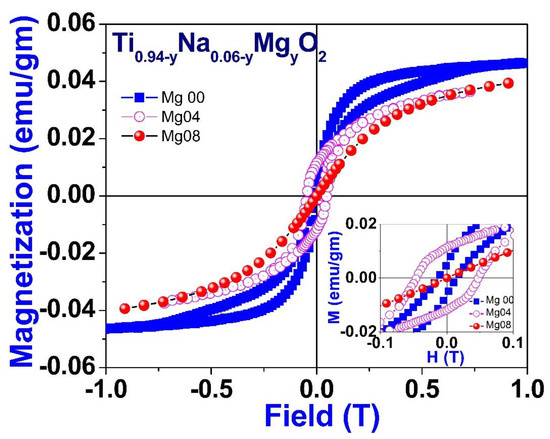
Figure 13.
Room temperature field variation of magnetization for Ti0.94-yNa0.06MgyO2 with y = 0, 0.04, and 0.08 compounds.
4. Conclusions
As a result, our investigations into the micro-structure, dielectric characteristics, optical properties, and magnetic properties of Ti0.94-yNa0.06MgyO2 with y = 0, 0.02, 0.04, 0.06, 0.08 compounds synthesized using the conventional solid-state approach have resulted in a number of fascinating discoveries.
- Microstructure:
Micrographs taken using a scanning electron microscope (SEM) reveal that the particles are round and measure between 20 and 70 μm in diameter. Elements were analyzed using energy dispersive x-ray to confirm that the synthesized compounds had similar elemental compositions to their precursors and that the elements were distributed uniformly throughout the complex.
- Oxidation states:
The XPS study suggests that Ti mostly resided in the Ti4+ oxidation state.
- Dielectric Properties:
The dielectric analysis shows that dielectric value and AC conductivity enhance with the increase of Na/Mg concentration. In addition to this, the compounds have a dielectric constant that is considerable and shows small dielectric loss. When analyzing a complicated impedance spectrum, grain and grain boundary conduction can be identified by configuring the Nyquist plot to correspond to an appropriate electrical circuit. It can be seen that when the concentration of co-doping increases, Rg and Rgb both go down, which is an indication that R is getting lower for the samples. Possible causes include surface roughness or lattice mismatch at the metal-semiconductor interface, as well as the impact of high R on carrier transport between the metal and the semiconductor.
- Nature of charge carrier and density:
Because the incorporation of Na and Mg into TiO2 results in the production of holes within the compounds, Hall effect tests reveal that all Na/Mg co-doped TiO2 compounds display p-type conductivity.
- Optical Properties:
The optical property measurement carried out using a UV–Vis spectrophotometer indicates without a shadow of a doubt that Na/Mg has been incorporated into the TiO2 matrix, which has led to a narrowing of the band gap. The transmittance value rises with increasing Mg concentration, going from 81% to 84% for 8%Na/Mg co-doped TiO2.
- Magnetic Property:
It has been shown that room-temperature ferromagnetic behavior is displayed by all of the Na/Mg co-doped TiO2 compounds.
In conclusion, the use of Na/Mg co-doping on p-type TiO2 samples unlocks potential applications in spintronics, optoelectronics, magnetic media, and storage devices.
Author Contributions
R.N.: Investigation, Methodology, Formal analysis, Writing Manuscript; B.D.: Investigation; A.M., S.S. and B.N.P.: Investigation; S.R.: Visualization, Resources, Writing—Review and Editing, Supervision; S.K.S.: Conceptualization, Methodology, Visualization, Writing—Review and Editing, Supervision. All authors have read and agreed to the published version of the manuscript.
Funding
This research received no external funding.
Institutional Review Board Statement
Not Applicable.
Informed Consent Statement
Not Applicable.
Data Availability Statement
The data that supports the findings of this study are available within the article.
Acknowledgments
This present research work is not supported by any kind of research grant.
Conflicts of Interest
The authors declare no conflict of interest.
References
- Ohno, H. Making nonmagnetic semiconductors ferromagnetic. Science 1998, 281, 951–956. [Google Scholar] [CrossRef]
- Chouhan, S.L.; Srivastava, K. A Comprehensive Review on Recent Advancements in d0 Ferromagnetic Oxide Materials for Spintronics Application. Mater. Sci. Semicond. Process. 2022, 147, 106768. [Google Scholar] [CrossRef]
- Furdyna, J.K. Diluted magnetic semiconductors. J. Appl. Phys. 1988, 64, R29. [Google Scholar] [CrossRef]
- Ogale, S.B.; Choudhary, R.J.; Buban, J.P.; Lofland, S.E.; Shinde, S.R.; Kale, S.N.; Kulkarni, V.N.; Higgins, J.; Lanci, C.; Simpson, J.R.; et al. High Temperature Ferromagnetism with a Giant Magnetic Moment in Transparent Co-doped SnO2−δ. Phys. Rev. Lett. 2003, 91, 077205. [Google Scholar] [CrossRef]
- Wang, X.L.; Dai, Z.X.; Zeng, Z. Evidence of carrier mediated room temperature ferromagnetism in transparent semiconducting Sn1−xCoxO2−δ thin films. J. Phys. Condens. Matter 2008, 20, 125208. [Google Scholar]
- Srivastava, S.K.; Lejay, P.; Barbara, B.; Boisron, O.; Pailhѐs, S.; Bouzerar, G. Absence of ferromagnetism in Mn-doped tetragonal zirconia. J. Appl. Phys. 2011, 110, 043929. [Google Scholar] [CrossRef]
- Srivastava, S.K. Magnetic Property of Mn-Doped Monoclinic ZrO2 Compounds. J. Supercond. Nov. Magn. 2020, 33, 2501. [Google Scholar] [CrossRef]
- Subramanian, M.; Thakur, P.; Tanemura, M.; Hihara, T.; Ganesan, V.; Soga, T.; Chae, K.H.; Jayavel, R.; Jimbo, T. Intrinsic ferro-magnetism and magnetic anisotropy in Gd-doped ZnO thin films synthesized by pulsed spray pyrolysis method. J. Appl. Phys. 2010, 108, 053904. [Google Scholar] [CrossRef]
- Bryan, J.D.; Heald, S.M.; Chambers, S.A.; Gamelin, D.R. Strong Room-Temperature Ferromagnetism in Co2+-Doped TiO2 Made from Colloidal Nanocrystals. J. Am. Chem. Soc. 2004, 126, 11640. [Google Scholar] [CrossRef]
- Srivastava, S.K.; Brahma, R.; Datta, S.; Guha, S.; Baro, S.S.; Narzary, B.; Basumatary, D.R.; Kar, M.; Ravi, S. Effect of (Ni-Ag) co-doping on crystal structure and magnetic Property of SnO2. Mater. Res. Express 2019, 6, 126107. [Google Scholar] [CrossRef]
- Srivastava, S.K.; Baro, S.S.; Narzary, B.; Basumatary, D.R.; Brahma, R.; Ravi, S. Crystal Structure and Magnetic Properties of (Co-Ag) co-doped SnO2 Compounds. J. Supercond. Nov. Magn. 2021, 34, 461–467. [Google Scholar] [CrossRef]
- Chouhan, L.; Bouzerar, G.; Srivastava, S.K. Effect of Mg-doping in tailoring d0 ferromagnetism of rutile TiO2 compounds for spintronics application. J. Mater. Sci. Mater. Electron. 2021, 32, 11193. [Google Scholar] [CrossRef]
- Osorio-Guillen, J.; lany, S.; Barabash, S.V.; Zunger, A. Magnetism without Magnetic Ions: Percolation, Exchange, and For-mation Energies of Magnetism-Promoting Intrinsic Defects in CaO. Phys. Rev. Lett. 2006, 96, 1072033. [Google Scholar] [CrossRef]
- Pan, H.; Yi, J.B.; Shen, L.; Wu, R.Q.; Yang, J.H.; Lin, J.Y.; Feng, Y.P.; Ding, J.; Van, L.H.; Yin, J.H. Room-Temperature Ferro-magnetism in Carbon-Doped ZnO. Phys. Rev. Lett. 2007, 99, 127201. [Google Scholar] [CrossRef]
- Young, D.P.; Hall, D.; Torelli, M.E.; Fisk, Z.; Sarrao, J.L.; Thompson, J.D.; Ott, H.-R.; Oseroff, S.B.; Goodrich, R.G.; Zysler, R. High-temperature weak ferromagnetism in a low-density free-electron gas. Nature 1999, 397, 412–414. [Google Scholar] [CrossRef]
- Máca, F.; Kudrnovský, J.; Drchal, V.; Bouzerar, G. Magnetism without magnetic impurities in ZrO2 oxide. Appl. Phys. Lett. 2008, 92, 212503. [Google Scholar] [CrossRef]
- Bouzerar, G.; Ziman, T. Model for Vacancy-Induced d0 Ferromagnetism in Oxide Compounds. Phys. Rev. Lett. 2006, 96, 207602. [Google Scholar] [CrossRef]
- Narzary, R.; Dey, B.; Chouhan, L.; Kumar, S.; Ravi, S.; Srivastava, S. Optical band gap tuning, zero dielectric loss and room temperature ferromagnetism in (Ag/Mg) co-doped SnO2 compounds for spintronics applications. Mater. Sci. Semicond. Process. 2022, 142, 106477. [Google Scholar] [CrossRef]
- Srivastava, S.K.; Lejay, P.; Barbara, B.; Pailh`es, S.; Madigou, V.; Bouzerar, G. Possible room-temperature ferromagnetism in K-doped SnO2: X-ray diffraction and high-resolution transmission electron microscopy study. Phys. Rev. B 2010, 82, 193203. [Google Scholar] [CrossRef]
- Srivastava, S.K.; Lejay, P.; Hadj-Azzem, A.; Bouzerar, G. Non-magnetic Impurity Induced Magnetism in Li-Doped SnO2 Na-noparticles. J. Supercond. Nov. Magn. 2014, 27, 487–492. [Google Scholar] [CrossRef]
- Wang, J.; Zhou, D.; Li, Y.; Wu, P. Experimental and first-principle studies of ferromagnetism in Na-doped SnO2 nanoparticles. Vacuum 2017, 141, 62–67. [Google Scholar] [CrossRef]
- Chouhan, L.; Panda, S.K.; Bhattacharjee, S.; Das, B.; Mondal, A.; Parida, B.; Brahma, R.; Manglam, M.K.; Kar, M.; Bouzerar, G.; et al. Room temperature d0 ferromagnetism, zero dielectric loss and ac-conductivity enhancement in p-type Ag-doped SnO2 compounds. J. Alloy. Compd. 2021, 870, 159515. [Google Scholar] [CrossRef]
- Srivastava, S.K.; Lejay, P.; Barbara, B.; Boisron, O.; Pailhès, S.; Bouzerar, G. Non-magnetic impurity induced magnetism in rutile TiO2:K compounds. J. Phys. Condens. Matter 2011, 23, 442202. [Google Scholar] [CrossRef]
- Chouhan, L.; Srivastava, S. Observation of room temperature d0 ferromagnetism, band-gap widening, zero dielectric loss and conductivity enhancement in Mg doped TiO2 (rutile + anatase) compounds for spintronics applications. J. Solid State Chem. 2022, 307, 122828. [Google Scholar] [CrossRef]
- Chouhan, L.; Narzary, R.; Dey, B.; Panda, S.K.; Manglam, M.K.; Roy, L.; Brahma, R.; Mondal, A.; Kar, M.; Ravi, S.; et al. Tailoring room temperature d0 ferromagnetism, dielectric, optical, and transport properties in Ag-doped rutile TiO2 compounds for spintronics applications. J. Mater. Sci. Mater. Electron. 2021, 32, 28163–28175. [Google Scholar] [CrossRef]
- Hou, D.L.; Meng, H.J.; Jia, L.Y.; Ye, X.J.; Zhou, H.J.; Li, X.L. Impurity concentration study on ferromagnetism in Cu-doped TiO2 thin films. Eur. Lett. 2007, 78, 67001. [Google Scholar] [CrossRef]
- Duhalde, S.; Vignolo, M.F.; Golmar, F.; Chiliotte, C.; Torres, C.E.R.; Errico, L.A.; Cabrera, A.F.; Rentería, M.; S´anchez, F.H.; Weissmann, M. Appearance of room-temperature ferromagnetism in Cu-doped TiO2−δ films. Phys. Rev. B 2005, 72, 161313. [Google Scholar] [CrossRef]
- Dimri, M.C.; Khanduri, H.; Kooskora, H.; Kodu, M.; Jaaniso, R.; Heinmaa, I.; Mere, A.; Krustok, J.; Stern, R. Room-temperature ferromagnetism in Ca and Mg stabilized cubic zirconia bulk samples and thin films prepared by pulsed laser deposition. J. Phys. D Appl. Phys. 2012, 45, 475003. [Google Scholar] [CrossRef]
- Chouhan, L.; Bouzerar, G.; Srivastava, S. d0 Ferromagnetism in Ag-doped monoclinic ZrO2 compounds. Vacuum 2020, 182, 109716. [Google Scholar] [CrossRef]
- Chawla, S.; Jayanthi, K.; Kotnala, R.K. High temperature carrier controlled ferromagnetism in alkali doped ZnOnanorods. J. Appl. Phys. 2009, 106, 113923. [Google Scholar] [CrossRef]
- Chouhan, L.; Bouzerar, G.; Srivastava, S.K. d0 ferromagnetism in Li-doped ZnO compounds. J. Mater. Sci. Mater. Electron. 2021, 32, 6389–6397. [Google Scholar] [CrossRef]
- Sharma, N.; Kant, R.; Sharma, V.; Kumar, S. Influence of Silver Dopant on Morphological, Dielectric and Magnetic Properties of ZnO Nanoparticles. J. Electron. Mater. 2018, 47, 4098–4107. [Google Scholar] [CrossRef]
- Deng, R.; Yao, B.; Li, Y.F.; Xu, Y.; Li, J.C.; Li, B.H.; Shen, D.Z. Ultraviolet electroluminescence from n-ZnO/p-NiO heterojunction light-emitting diode. J. Lumin. 2013, 134, 240. [Google Scholar] [CrossRef]
- Ahmed, F.; Kumar, S.; Arshi, N.; Anwar, M.S.; Heo, S.N.; Kim, G.W.; Lu, J.; Koo, B.H. Room-temperature Ferromagnetism in Cu-doped ZnONanorods Prepared Using a Microwave Irradiation Method. J. Korean Phys. Soc. 2012, 60, 1644. [Google Scholar] [CrossRef]
- Li, J.; Li, Y.; Li, S.; Zhu, M.; Zhang, J.; Li, Y.; He, Y.; Li, W. Zinc interstitial and oxygen vacancy mediated high Curie-temperature ferromagnetism in Ag-doped ZnO. Ceram. Int. 2020, 46, 18639–18647. [Google Scholar] [CrossRef]
- Dey, B.; Narzary, R.; Chouhan, L.; Bhattacharjee, S.; Parida, B.N.; Mondal, A.; Ravi, S.; Srivastava, S.K. Crystal structure, optical and dielectric properties of Ag:ZnO composite-like compounds. J. Mater. Sci. Mater. Electron. 2022, 33, 2855. [Google Scholar] [CrossRef]
- Chakraborti, D.; Narayan, J. Room temperature ferromagnetism in Zn1−𝑥Cu𝑥O thin films. Appl. Phys. Lett. 2007, 90, 062504. [Google Scholar] [CrossRef]
- Chawla, S.; Jayanthi, K.; Kotnala, R.K. Room-temperature ferromagnetism in Li-doped p-type luminescent ZnOnanorods. Phys. Rev. B 2009, 79, 125204. [Google Scholar] [CrossRef]
- Dey, B.; Srivastava, S.K. Crystal structure, microstructure, optical, dielectric and magnetic properties of TiO2 nanoparticles. J. Mater. Sci. Mater. Electron. 2022, 33, 23506–23514. [Google Scholar] [CrossRef]
- Ghosh, S.; Khan, G.G.; Das, V.; Mandal, K. Vacancy-induced intrinsic d0 ferromagnetism and photoluminescence in potas-sium doped ZnO nanowires. J. Appl. Phys. 2011, 109, 123927. [Google Scholar] [CrossRef]
- Huang, Y.; Zhou, W.; Wu, P. Room-temperature ferromagnetism in epitaxial p-type K-doped ZnOfilms. Solid State Commun. 2014, 183, 31. [Google Scholar] [CrossRef]
- Dey, B.; Narzary, R.; Panda, S.K.; Mallick, J.; Mondal, A.; Ravi, S.; Kar, M.; Srivastava, S. Room temperature d0 ferromagnetism, band-gap reduction, and high optical transparency in p-type K-doped ZnO compounds for spintronics applications. Mater. Sci. Semicond. Process. 2022, 148, 106798. [Google Scholar] [CrossRef]
- Zhang, H.; Wang, Y.; Wang, H.; Huo, D.; Tan, W. Room-temperature magnetoresistive and magnetocaloric effect in La1−xBaxMnO3 compounds: Role of Griffiths phase with ferromagnetic metal cluster above Curie temperature. J. Appl. Phys. 2022, 131, 043901. [Google Scholar] [CrossRef]
- Dey, B.; Panda, S.K.; Mallick, J.; Sen, S.; Parida, B.; Mondal, A.; Kar, M.; Srivastava, S. Observation of room temperature d0 ferromagnetism, bandgap narrowing, zero dielectric loss, dielectric enhancement in highly transparent p-type Na-doped rutile TiO2 compounds for spintronics applications. J. Alloy. Compd. 2023, 930, 167442. [Google Scholar] [CrossRef]
- Koops, C.G. On the Dispersion of Resistivity and Dielectric Constant of Some Semiconductors at Audiofrequencies. Phys. Rev. (Series I) 1951, 83, 121–124. [Google Scholar] [CrossRef]
- Srivastava, S.K.; Ravi, S. The Effect of Co Substitution on the Crystal Structure and Electrical Resistivity of (La0.85Ag0.15)MnO3 Compounds. J. Supercond. Nov. Magn. 2009, 22, 651–658. [Google Scholar] [CrossRef]
- Srivastava, S.K.; Kar, M.; Ravi, S. Ferromagnetic insulating and spin glass behavior in Cr substituted La0.85Ag0.15MnO3compounds. J. Phys. Condens. Matter 2008, 20, 235201. [Google Scholar] [CrossRef]
- Tauc, J.; Grigorovici, R.; Vancu, A. Optical Properties and Electronic Structure of Amorphous Germanium. Phys. Status Solidi B 1966, 15, 627–637. [Google Scholar] [CrossRef]
Publisher’s Note: MDPI stays neutral with regard to jurisdictional claims in published maps and institutional affiliations. |
© 2022 by the authors. Licensee MDPI, Basel, Switzerland. This article is an open access article distributed under the terms and conditions of the Creative Commons Attribution (CC BY) license (https://creativecommons.org/licenses/by/4.0/).

