Article

Experimental and Numerical Analysis of the Assisted Abrasive Flow of Magnetic Particles on the Polishing of Fuel Injection Nozzles

1
Department of Mechanical and Electrical Engineering, East Campus of Changchun University of Science and Technology, Changchun 130022, China
2
Department of Mathematics and Physics, Changchun Institute of Technology, Changchun 130012, China
3
School of Mechatronic Engineering and Automation, Foshan University, Foshan 528225, China
*
Author to whom correspondence should be addressed.
Magnetochemistry 2022, 8(3), 35; https://doi.org/10.3390/magnetochemistry8030035
Submission received: 4 December 2021 / Revised: 15 March 2022 / Accepted: 16 March 2022 / Published: 21 March 2022

Abstract

:
Fuel injection nozzles are a key component of electronic injection engines, and their inner surface roughness affects the performance of the nozzles and restricts the working efficiency of the engine. Therefore, the polishing technology for a nozzle’s inner surface is particularly important. At present, abrasive flow polishing technology is commonly used to treat the inner surfaces of the nozzles. This study investigated the magnetic particles in the abrasive flow working medium. Due to the external magnetic field, magnetic particles are affected by the magnetic field force and change the polishing performance of the abrasive flow working medium. Through a numerical analysis and contrast experimental research, we can see that the choice of different grinding grain sizes, kinematic viscosity, magnetic field intensity, and process parameters, such as inlet pressure, with magnetic particles in a solid–liquid two-phase abrasive flow for polishing, can effectively improve the quality of the injection nozzle’s inner surface. The study also reveals that the influence of the nozzle’s inner surface polishing quality is significant and creates a mechanism for process parameters.

1. Introduction

The fuel injection nozzles studied for this paper are a key component of electronic injection engines, and their inner surface roughness seriously affects the performance of the nozzles. Therefore, after the nozzle workpiece is processed, the inner surface of the nozzle needs to be treated with precision polishing [1,2,3]. It is difficult to achieve the precision machining requirements of a nozzle’s surface with traditional machining technology; therefore, this study utilized abrasive flow ultra-precision machining technology, which has controllable parameters, a stable processing effect, and excellent processing qualities, and is widely used in the field of ultra-precision machining [4].
Abrasive flow ultra-precision machining technology has a mild material removal mechanism, and in recent years a growing number of scholars have increasingly become attentive to it. Li Junye [5,6,7,8] et al. utilized a T-tube, nozzle, and U-tube in their research. They carried out a numerical simulation, experimented on the abrasive flow finishing process, discussed the influence of the process parameters on the surface quality of parts, and provided a technical reference for the optimization of the abrasive flow machining theory. The relationship between temperature and turbulent kinetic energy, turbulent kinetic energy and velocity, and temperature and processing speed were determined, which provides a theoretical basis for controlling the quality of abrasive flow polishing. Sachin Singh [9,10] et al. used abrasive flow processing technology to study the parameterization of 316 L surgical stainless-steel tubes, developed a local multi-polymer mixed base media for nano-finishing experiments, and proposed a statistical model. Venkatesh G [11,12] et al. proposed ultrasonic-assisted abrasive flow processing technology. Through a finite element simulation, a 3D model was built to simulate the flow of the medium through the outer wall of the gear surface, and the effectiveness was verified through experiments. According to the experimental results, the improvement of the surface quality and material removal was significantly greater than that obtained by using traditional abrasive flow machining. This study shows that the high-frequency ultrasonic vibration applied to a workpiece has the greatest impact on the process response of the considered variables. Huang Yong [13] et al. used the computational fluid dynamics (CFD) method to simulate the gas–solid two-phase flow field in a faucet elbow, studied the trajectory of rock debris particles in the elbow and the distribution of wall wear, and further revealed the influence of rock debris characteristics on the wall wear. Anand C. Petare [14] put forward a study on laser-texturized auxiliary abrasive flow finishing technology for hobbing spur gears to improve the micro-geometry, surface finish, micro-hardness, micro-structure, and wear resistance of the spur gears further, which can significantly improve the productivity of abrasive flow processing technology.
In this study, magnetic particles were added on the basis of traditional abrasive flow polishing technology, and an external magnetic field was applied to ensure the magnetic particles drove the abrasive to perform more effective precision machining on the wall surface under the action of a magnetic field. In recent years, Wang Ningning [15] et al. intensively studied the microscopic characteristics of magnetorheological fluid (MRF) in a magnetic field. The numerical simulation and industrial CT results indicate that the chain structure of the MRF becomes more apparent as the magnetic field’s strength increases. S. Kathiresan [16] et al. improved the surface quality of 316 L stainless steel to the nanometer level by adopting the MR abrasive flow polishing process. In order to determine the influence of the input process parameters on the responses, such as the final surface roughness and material removal rate, a response surface model was established, and the optimal parameters were identified through an expectation analysis. In order to solve the corrosion problem caused by the oxidation of hydroxy iron powder (CI) particles in magnetorheological polishing (MRF), scholars, such as Jung-Won Lee [17,18] et al., used xanthan gum biopolymer to coat the CI particles to improve the magnetorheological polishing and used a rotary rheometer to measure the characteristics of the magnetic fluid under different magnetic fields. By changing the experimental data, the relevant experiments were carried out. The experimental results confirmed that xanthan gum-coated CI particles could be used for the magnetorheological polishing of BK7 glass holes. Based on the experimental rheological properties of various abrasive media and the assumption of continuous media, Youzhi Fu [19] et al. established a flow field simulation model of the abrasive media. A pressure detection platform was built for the constrained channel, and the test and simulation data were compared and analyzed. The results showed that, under the same mass fraction, the abrasive diameter has little effect on the rheological properties of the abrasive, and the rheological properties of the abrasive before and after use conform to the power–law constitutive model. The pressure in the constrained channel increases with an increase in the extrusion pressure and decreases along the flow direction, which makes the grinding trace shallower along the flow direction. In order to develop an efficient and high-quality ultra-smooth surface processing technology for zirconia ceramics, Guo Meijian [20] et al. studied the influence of different process parameters on the planar magnetorheological machining performance of zirconia ceramics and analyzed the material removal rate and surface roughness. The results showed that the high efficiency and super smooth surface processing of zirconia ceramics could be realized by using the magnetorheological polishing method. Through experiments, Dilshad Ahmad Khan [21,22] explored the issues related to ball-end MR finishing, developed fluid compositions suitable for copper finishing, and obtained a nanosurface with very few shallow scratches.
At present, scholars have a deep understanding of abrasive flow precision machining technology, and there is also good research available on magnetorheological polishing technology. However, research on solid–liquid two-phase magnetic fluid precision polishing is not enough, and the precision polishing mechanism, quality control, and prediction are deficient.
In this study, a numerical model of abrasive flow precision polishing with magnetic particles was established based on abrasive flow precision machining technology and the magnetorheological polishing process. The reliability of the model was verified by experiments, and the significant order of the process parameters affecting the polishing quality of the nozzle’s inner surface was revealed.

2. Materials and Methods

2.1. Principle Analysis of Abrasive Flow Processing Technology Containing Magnetic Particles

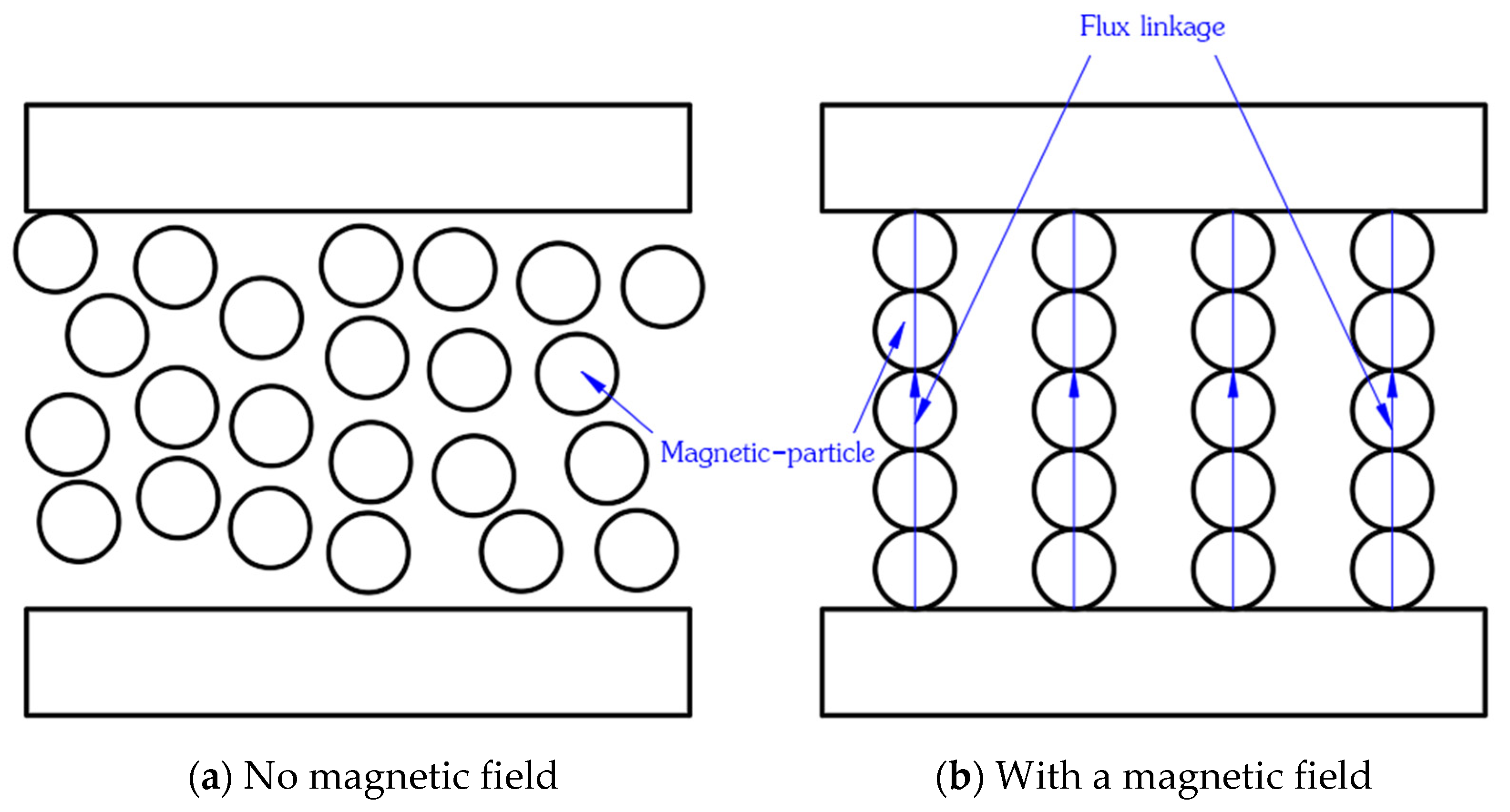
The principle of the abrasive flow processing of magnetic particles is shown in Figure 1 and Figure 2. The abrasive flow polishing fluid reciprocates in the flow path under the action of the upper and lower hydraulic cylinders, and the surface of the workpiece is fixed in the magnetic field through the fixture, becoming part of the flow path. When abrasive flow polishing fluid flows under the pressure of an external hydraulic cylinder, it quickly moves through the workpiece surface area, and the rheological effect appears rapidly; the liquid viscosity of the abrasive flow polishing increases rapidly, the shear yield stress increases, and the magnetic particles under the action of a magnetic field tend to stick on the surface, thus driving the surface of the abrasive clamping workpiece. Under the pressure of the hydraulic cylinder, the abrasive flow polishing fluid on the surface of the workpiece moves back and forth so as to realize the finishing of the workpiece.

2.2. Three-Dimensional Magnetostatic Analysis Theory of Abrasive Flow Processing Technology Containing Magnetic Particles

The basic Maxwell equations of the static magnetic field in three dimensions are shown in Equation (1):
{ × H ( x , y , z ) = J ( x , y , z ) · B ( x , y , z ) = 0
where B (x, y, z) is the magnetic induction intensity, H (x, y, z) is the magnetic field intensity, and J (x, y, z) is the current density. These three vectors are all functional relations of the vectors in all directions, as shown in Equation (2):
B ( x , y , z ) = B x · i + B y · j + B z k  
where B x , B y , and B z are scalar magnetic induction intensities in the three directions.
A permanent magnet can be described in terms of Equation (3):
B = μ 0 · μ r · H + μ 0 · M p
where μ 0 = 4 π × 10 7 H / m   is the absolute permeability in vacuum, μ r is the relative permeability, and M P is the polarization strength of permanent magnet material.
For anisotropic magnetic materials, a three-dimensional static magnetic field is treated as a relative permeability tensor, namely:
μ r = [ μ r x       μ r y   μ r z   ]
The calculation of anisotropy is realized by describing different relative permeability in three directions. The magnetic field intensity H can be described by Equation (5):
H = H p + φ + H c
where ϕ is the scalar magnetic potential; H p is the magnetic field intensity on the six sides of the tetrahedron, which is also the field quantity to be calculated; and H c is the magnetic field intensity on the permanent magnet. The tetrahedron requires up to 10 degrees of freedom to be solved, four of which have scalar magnetic potential on four vertices of the tetrahedron, and the other six have magnetic induction intensity on six sides of the tetrahedron, which can be approximated by the field quantity in a single subdivision unit through quadratic interpolation.
In magnetic grinding, a single magnetic particle generates grinding pressure, as shown in Equation (6).
P r = B 2 2 μ 0 ( 1 1 μ r )
The mathematical model of the extrusion force of abrasive flow on the inner surface of the nozzle is shown in Equation (7):
P w = P 0 1 ( 1 μ s k N l ) e x p [ 2 μ S ( 1 μ s k N l ) R ( d v t ) ]
where Pw is the extrusion pressure generated by the abrasive flow on the inner surface of the nozzle, P0 is inlet pressure, kNl is the stress difference coefficient, R is the pipeline diameter, μs is the friction coefficient, d is the abrasive particle diameter, v is the abrasive flow rate, and t is time.
The total pressure on the inner surface of the nozzle is P:
P = P w + P r

3. Numerical Analysis of the Abrasive Flow Machining Nozzle with Magnetic Particles

Before the fluid calculation, the following parameters needed to be set in the software: The choice was based on the stress analysis solver and, therefore, did not consider changing the heat and gravity; the abrasive flow of an incompressible fluid, fluid property, and grain were constant; and, by using kerosene as the continuous phase containing magnetic particles, the second phase was composed of silicon carbide particles. Through these assumptions, this problem was simplified into a three-dimensional, unsteady, physical property and a physical model without an inner heat source. The calculated Reynolds coefficient was less than 2300, indicating that the fluid had not developed into turbulence. Therefore, the laminar flow model was selected, the fluent calculation commenced, and the mixture model was selected in the multiphase model dialog box. The boundary type and boundary conditions were set as follows: The inlet condition was set as the velocity inlet (the pressure of the piston determined the flow velocity of the fluid), and the direction was perpendicular to the inlet boundary. In the actual process, the outlet was directly connected to the reflux unit, and there was no other pressure load, so the outlet was set to atmospheric pressure. The wall condition was a no-slip boundary condition. The abrasive volume fraction was set to 10%, and the surrounding magnetic field produced a magnetic force on the magnetic particles. The magnetic force was mainly calculated through Equation (6), which can be added through the UDF file. UDF is a function written by the user in the C programming language, which can be dynamically linked with FLUENT.

3.1. Modeling and Parameter Setting of Five-Hole Nozzle

This section utilizes the nozzle with five holes on the top as the research object. The nozzle geometry model is shown in Figure 3, the schematic diagram of the size and area division is shown in Figure 4, and the schematic diagram of the grid division is shown in Figure 5. The quality of the grid was tested, and there was no negative volume, indicating that the quality of the grid is reliable, and the grid quality of the nozzle is greater than 0.3, which meets the accuracy requirements of a simulation. Figure 6 depicts the grid quality inspection chart. An analysis of the negative volume in the FLUENT grid check revealed the existence of negative volume, which indicates that there is an incorrect connection; the error area can be displayed in this graphic window.

3.2. Analysis of Wall Shear Force Nephogram of Five-Hole Nozzle with Different Machining Parameters

The processing parameters A (abrasive particle size; the inlet pressure of the piston here determines the velocity of the abrasive flow), B (kinematic viscosity), C (voltage strength of the electromagnet), and D (inlet pressure) were selected as the numerical analysis parameters, and an orthogonal analysis was conducted. The orthogonal test table is shown in Table 1.
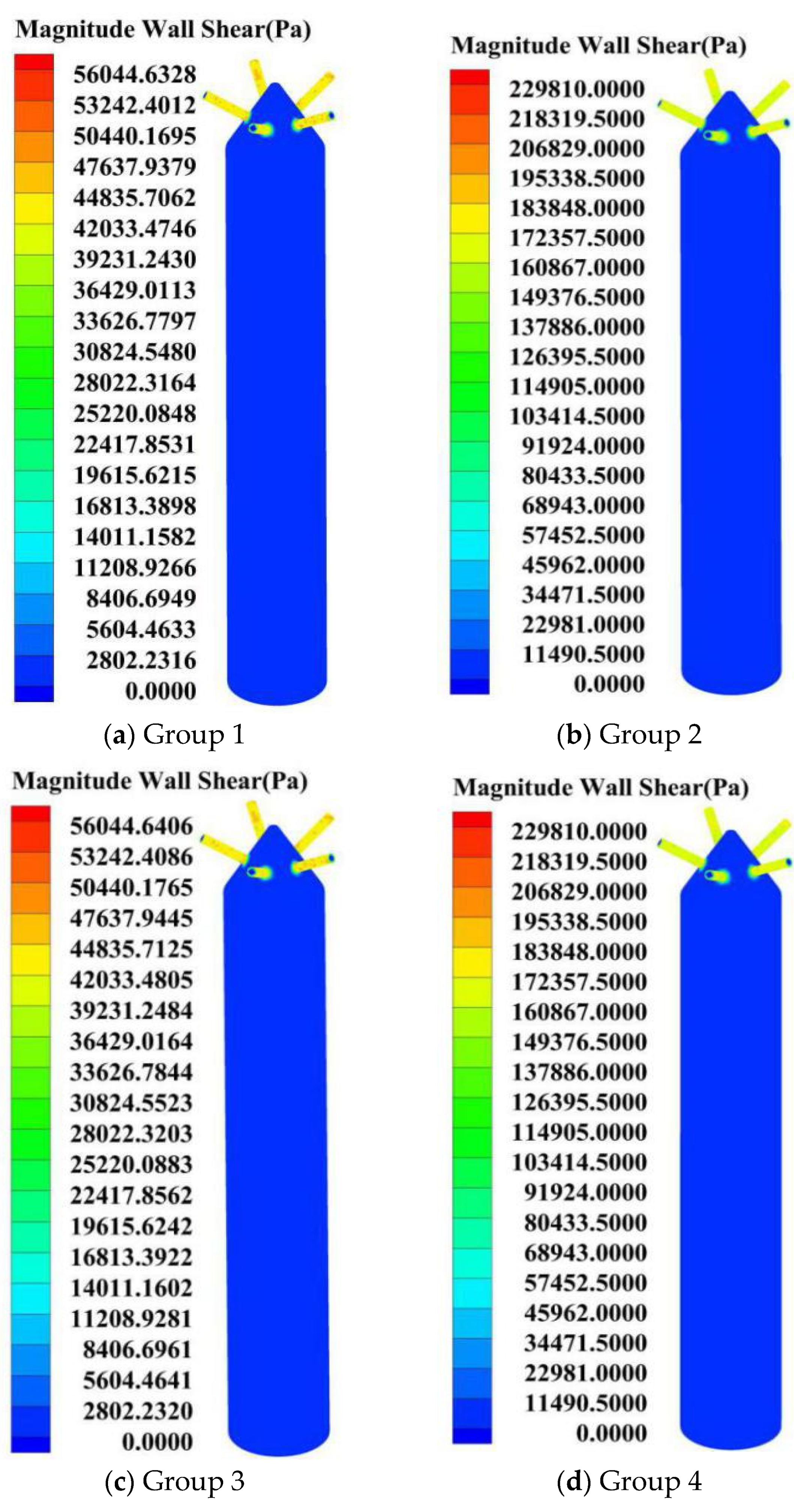
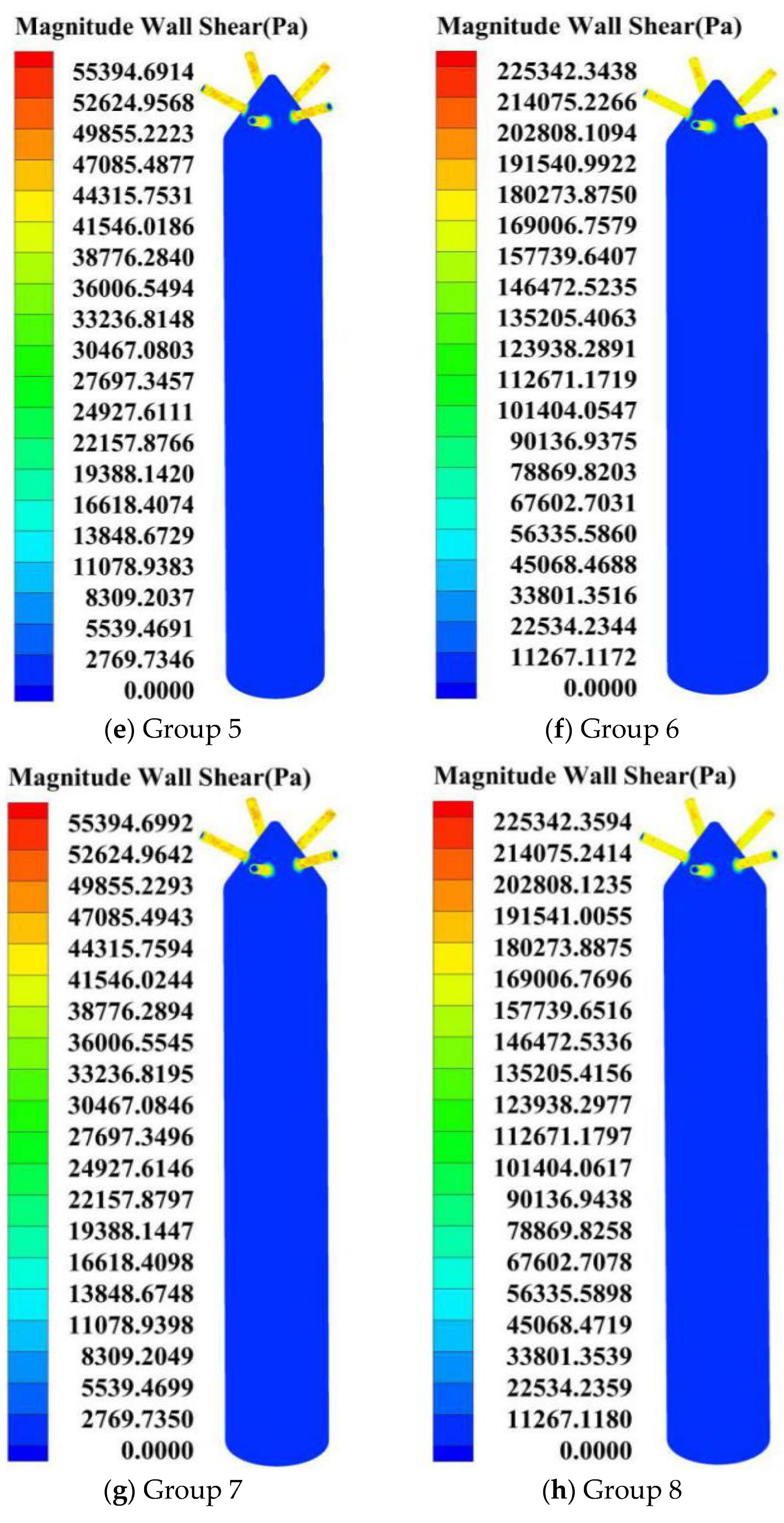
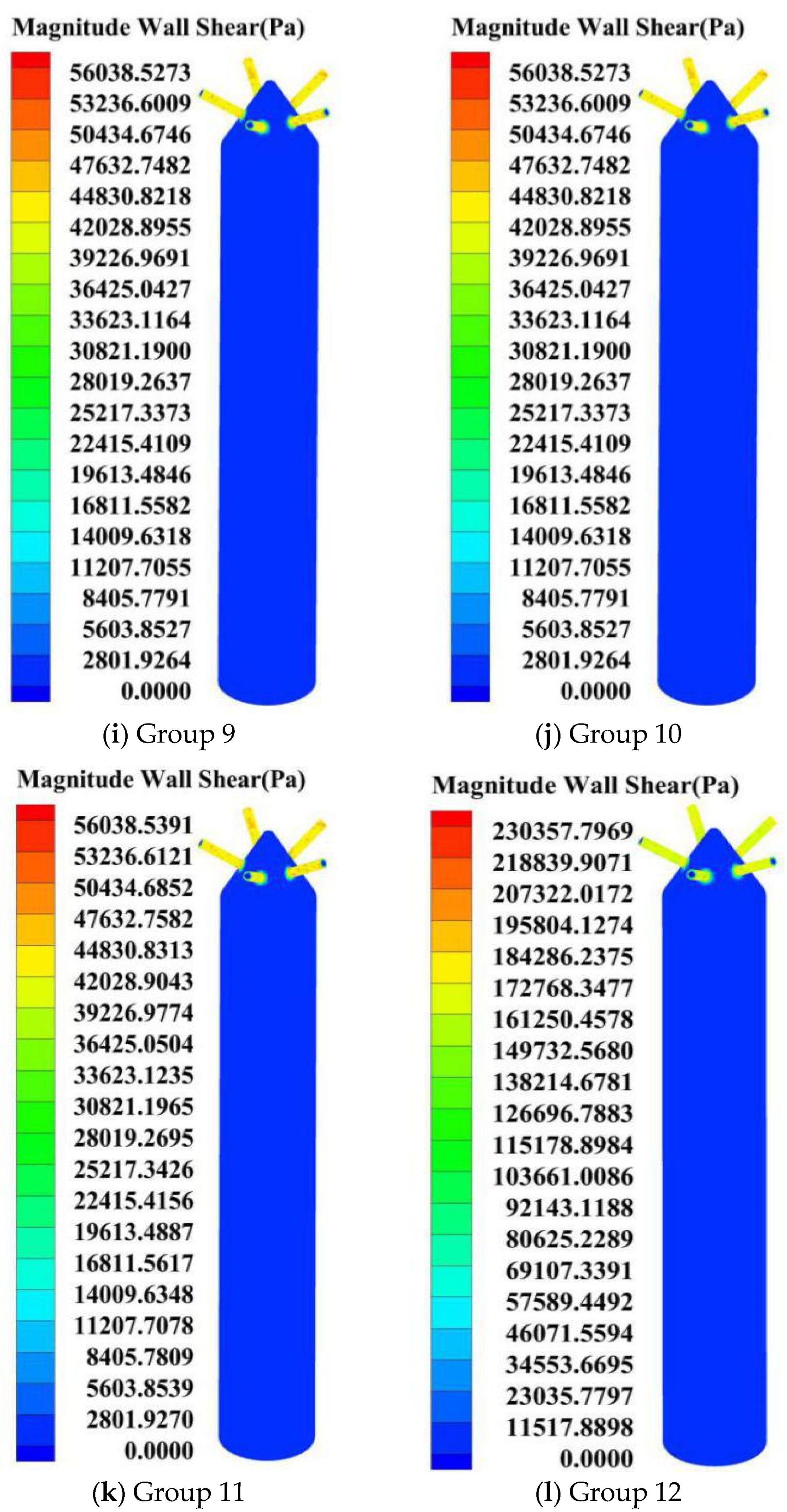
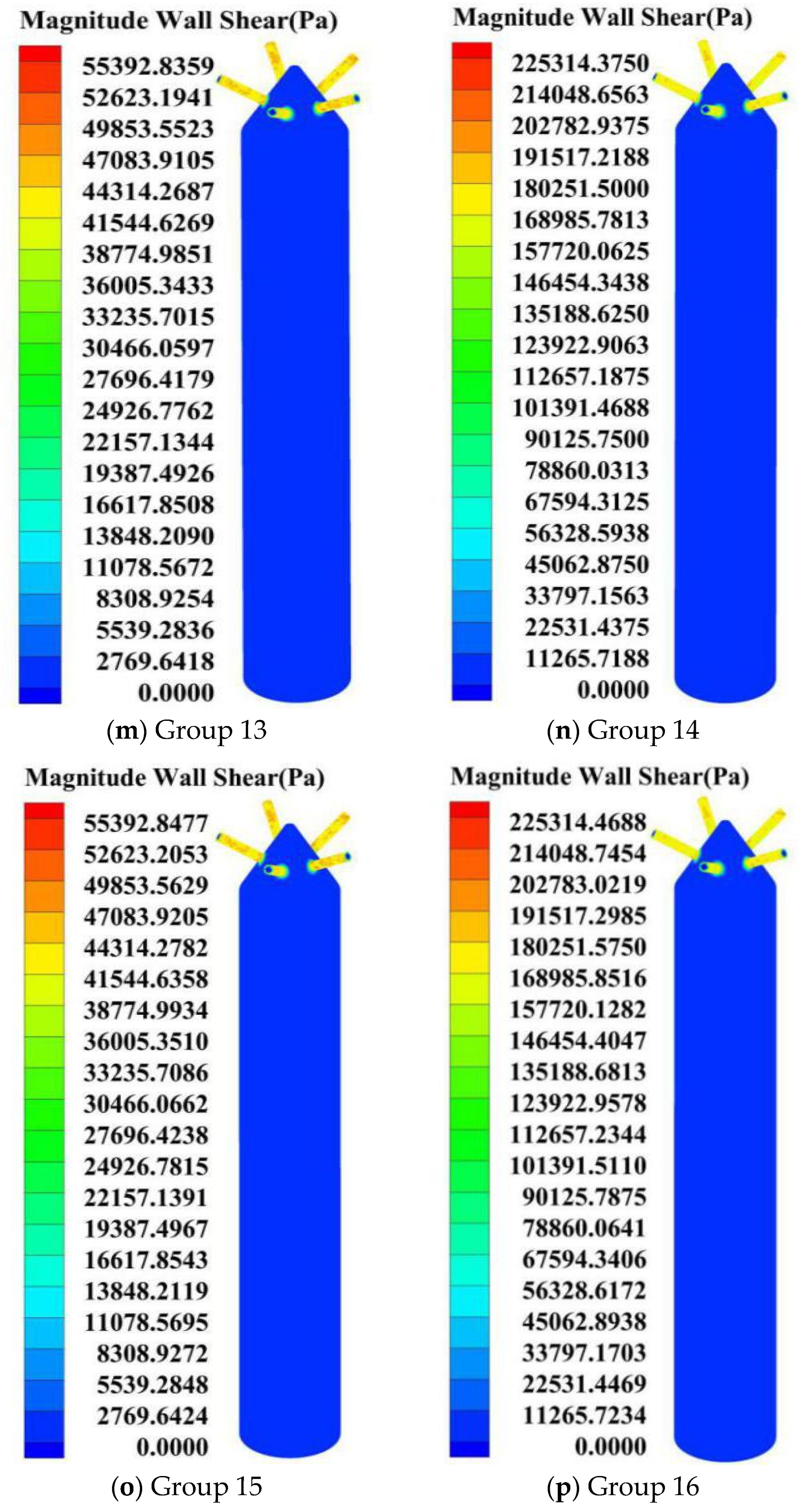
According to the numerical analysis of the parameters in Table 1, the nephogram of the wall shear stress was obtained, as shown in Figure 7.
Table 2 shows a comparison table of the wall shear stress of each area of the five-hole nozzle.
The analyses in Table 2 and Table 3 show: (1) A contrast in the groups 1, 8, 13, 18, 21, 25, 27, and 30 of the inlet pressure of the wall shear stress analysis and comparison, indicating a wall shear stress change difference of 310%, 310%, 307%, 307%, 311%, 311%, and 307%, respectively, and an improvement of the nozzle inlet pressure; moreover, the wall shear stress will increase, and the solid–liquid two-phase of the magnetic fluid precision polishing nozzle’s inner surface quality will get better. (2) Through comparison and analysis of the magnetic field intensity of the comparison groups 2, 5, 14, 16, 22, 23, 28, and 29, it was found that the difference of the wall shear stress change is basically 0, which shows that the influence of the magnetic field intensity on the wall shear force is negligible. (3) According to the comparative analysis of the kinematic viscosity of the comparison groups 3, 6, 9, 11, 24, and 26, the difference of the wall shear stress in each group was 1.2%, 2%, 1.2%, 2%, 2.2%, and 2.2%, respectively. Changing the kinematic viscosity has a certain influence on the wall shear force; increasing the kinematic viscosity will reduce the wall shear force. (4) Through the comparative analysis of the wear particle sizes of the groups 4, 7, 10, 12, 15, 17, 19, and 20, it was found that the difference in the wall shear stress was 0, except for group 7 and group 12, which were 0 in the other groups. The effect of the abrasive particle size on the wall shear stress was weak. The specific effect of the abrasive flow in [23] sets out relevant articles.
Under the conditions of this study, the wall shear force, and the precision polishing quality of the solid–liquid two-phase magnetic fluid in the three regions, were: large hole area < variable diameter area < small hole area and the influence of the inlet pressure on the wall shear force was significant; the higher the inlet pressure, the greater the wall shear force. The influence of the kinematic viscosity on the wall shear force was second, where the greater the kinematic viscosity, the smaller the wall shear force, and the particle size only had a small influence. The larger the particle size, the smaller the particle size and the smaller the shear force on the wall surface. The magnetic field intensity had a certain influence on the polishing quality. Increasing the magnetic field intensity could improve the wall shear force but increasing the magnetic field intensity had a limited effect on improving the nozzle quality of the solid–liquid two-phase magnetic fluid precision polishing.

4. Experimental Study of Solid–Liquid Two-Phase Magnetic Fluid Precision Polishing for Five-Hole Nozzle

In order to verify the accuracy of the numerical analysis results, an experiment of precision machining a five-hole nozzle with magnetic particles was carried out. The components of the abrasive flow polishing fluid used in this study were as follows: Aviation kerosene with a suitable density and good fluidity at low temperature was used as a base carrier liquid; hydroxyl iron powder with high magnetic conductivity and a stable chemical property was used as a sensitive magnetic particle; silicon carbide with high hardness and good self-sharpening ability was used as the abrasive material and various additives. The magnetic field used in this experiment was obtained using an electromagnet. The electromagnet changes the magnetic force of the magnetic field by adjusting the voltage. Because the workpiece and the inner channel are cylindrical, the selected magnet has a central hole structure, and the force direction of the workpiece under the action of the electromagnet is perpendicular to the wall and diverges outward.

4.1. Selection of a Five-Hole Nozzle

The nozzle with five-holes on the top was selected for the experimental research. The base material of the selected nozzle was 304 stainless steel. The physical pictures of the five-hole nozzle and wire cutting are shown in Figure 8.

4.2. Selection of Test Parameters

The inlet pressure, magnetic field intensity, kinematic viscosity, and particle size were selected as the abrasive flow processing parameters for the numerical simulation. In this study, the inlet pressures of 1 MPa, 2 MPa, 3 MPa, and 4 MPa were selected, and the input voltage that determined the strength of the magnetic field was 10 V, 20 V, 30 V, and 40 V. The kinetic viscosity was 0.7 Pa·s, 0.9 Pa·s, 1.01 Pa·s, and 1.16 Pa·s. The particle sizes were 500 mesh, 800 mesh, 1000 mesh, and 1200 mesh. The orthogonal experimental design results are shown in Table 4.

4.3. Profile Detection and Data Analysis of Optical Profilometer

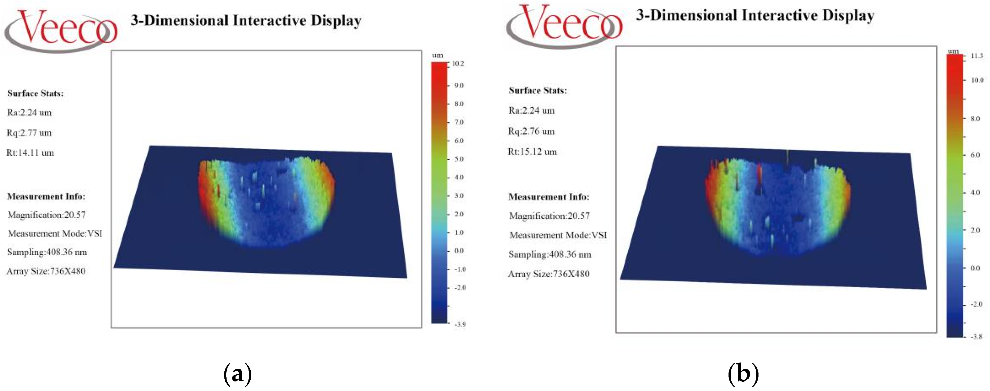
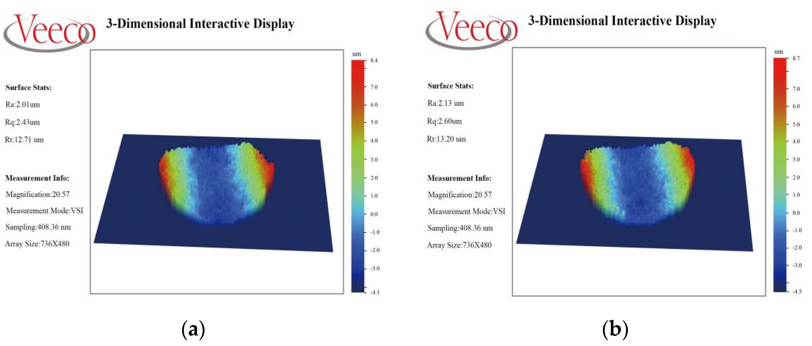
In order to clearly observe the improvement of the roughness in the nozzle’s inner surface before and after processing, an optical profilometer was used in the experiment to select the same observation points for the inner surface detection of the nozzle workpiece, and the inner surface contour detection diagram of the nozzle workpiece was obtained, as shown in Figure 9, Figure 10, Figure 11, Figure 12 and Figure 13. Due to a large number of detected workpieces, the paper selected were the originals, test no. 04 and test no. 08 and the test diagram composition reference; other workpiece detection diagram morphology was basically the same.
It can be seen from the inspection chart that the surface shape is uneven and has burrs and impurities before the grinding flow containing the magnetic particles is accurately machined, irrespective of the small hole area or the variable diameter area. The inner surface of the workpiece becomes smooth after the precision machining of the abrasive flow containing the magnetic particles, and the surface roughness of the workpiece before machining is also greatly reduced. Table 5 shows a summary of how the roughness values of the hole are measured with the Mahr probe.
It can be seen from Table 5 that the roughness value of the nozzle workpiece’s small hole area before the abrasive flow processing was 0.336 μm. After the abrasive flow precision polishing, the optimal roughness value of the small hole area could reach 0.075 μm, and the surface roughness was reduced by one order of magnitude, confirming the effectiveness of the solid–liquid two-phase magnetic fluid precision polishing technology. The surface quality can be effectively predicted and improved by this technology. According to the data obtained from the orthogonal test, the polishing quality of the inner surface of the nozzle was compared under different process parameters.
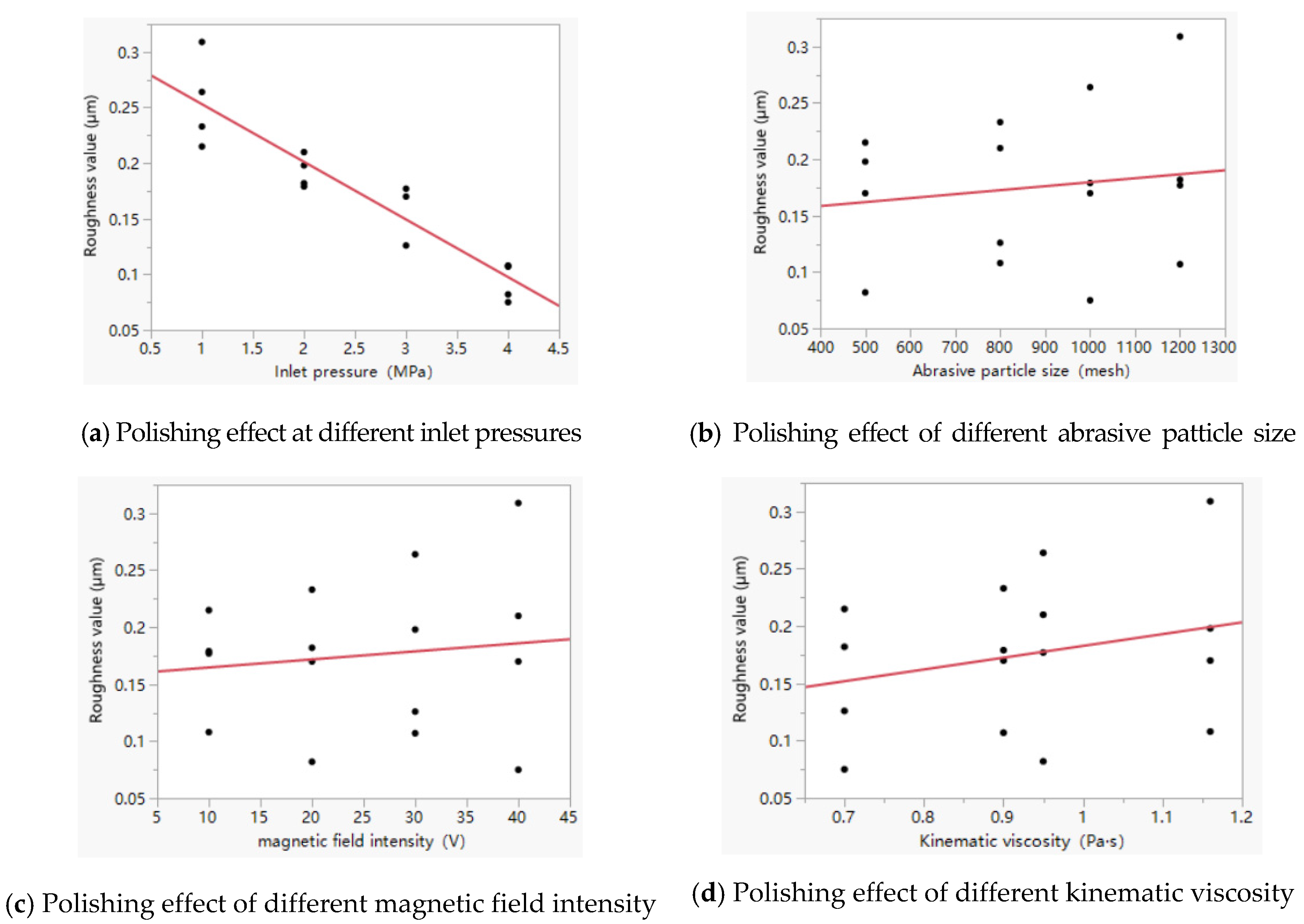
It can be seen from Figure 14 that the inlet pressure (intercept 19.46) has a significant impact on the polishing quality of the inner surface of the nozzle. The higher the inlet pressure, the more obviously the roughness decreases. The abrasive particle size (intercept 2.47) and magnetic field intensity (intercept 3.87) have a slight effect on the polishing quality of the nozzle’s inner surface. The kinematic viscosity (intercept 0.86) has no obvious effect on the polishing quality of the inner surface of the nozzle, which can be temporarily ignored in the following experimental design. In a numerical simulation, the quantitative description method of the kinematic viscosity needs to be further explored, and the wall shear force cannot fully reflect the polishing effect. Therefore, this study continues to carry out a partial analysis of a full-factor experiment. Drawing upon the Six Sigma theory, the experimental design and data testing are shown in Table 6.
According to the standard least square method, the magnetic particles have an intense interaction with the inlet pressure and particle size under the action of the external magnetic field, as shown in Figure 15, which indicates that the improvement trend of the nozzle’s inner surface roughness is not determined by a single main factor, and the interaction relationship is more important.

5. Conclusions

This study shows that the solid–liquid two-phase abrasive flow polishing technology containing magnetic particles can effectively improve the quality of an injection nozzle’s inner surface. The addition of the magnetic particles changes the solid–liquid two-phase abrasive flow polishing mechanism’s fluid kinematic viscosity and character. The need for a separate quantitative test led to the numerical simulation and experimental tests on the deviation. This study provides a new research direction for the improvement of solid–liquid two-phase abrasive flow polishing technology.

Author Contributions

Data curation, J.Q.; Methodology, J.L.; Project administration, G.L.; Supervision, J.L. and X.Z. (Xinming Zhang); Writing–original draft, S.Z.; Writing–review & editing, X.Z. (Xu Zhu). All authors have read and agreed to the published version of the manuscript.

Funding

This research was funded by the National Natural Science Foundation of China No. NSFC 51206011, Jilin Province, Science and Technology Development Program of Jilin Province No. 20200301040RQ, Changchun, and the Science and Technology Program of Changchun City No. 18DY017.

Institutional Review Board Statement

Not applicable.

Informed Consent Statement

Not applicable.

Data Availability Statement

Not applicable.

Conflicts of Interest

The funders had no role in the design of the study, in the collection, analyses, or interpretation of data, in the writing of the manuscript, or in the decision to publish the results.

References

  1. Zhao, J.; Jiang, E.; Qi, H.; Ji, S.; Chen, Z. A novel polishing method for single-crystal silicon using the cavitation rotary abrasive flow. Precis. Eng. 2020, 61, 72–81. [Google Scholar] [CrossRef]
  2. Wei, H.; Peng, C.; Gao, H.; Wang, X.; Wang, X. On establishment and validation of a new predictive model for material removal in abrasive flow machining. Int. J. Mach. Tools Manuf. 2019, 138, 66–79. [Google Scholar] [CrossRef]
  3. Wang, T.; Chen, D.; Zhang, W.; An, L. Study on key parameters of a new abrasive flow machining (AFM) process for surface finishing. Int. J. Adv. Manuf. Technol. 2019, 101, 39–54. [Google Scholar] [CrossRef]
  4. Sudhakara, D.; Suresh, S.; Vinod, B. Experimental Study on Abrasive Flow Machining (AFM): New Approach for Investigation on Nano-SiC in the Improvement of Material Removal and Surface Finishing. J. Bio-Tribo-Corr. 2020, 6, 24–35. [Google Scholar] [CrossRef]
  5. Li, J.-Y.; Zhou, Z.; Wei, L.; Zhang, X.; Xu, Y. Quality influence and process parameter optimization of T-pipe in abrasive flow finishing. Adv. Mech. Eng. 2017, 9, 2179–2187. [Google Scholar] [CrossRef] [Green Version]
  6. Li, J.; Yang, L.; Liu, W.; Zhang, X.; Sun, F. Experimental research into technology of abrsive flow maching non-linear tube runner. Adv. Mech. Eng. 2017, 6, 1283–1287. [Google Scholar]
  7. Li, J.; Yang, Z.; Liu, W.; Cai, W.; Qiao, Z. Numerical thermodynamic analysis of two-phase solid-liquid abrasive flow polishing in u-type tube. Adv. Mech. Eng. 2014, 8, 1–17. [Google Scholar] [CrossRef]
  8. Liu, G.; Zhang, X.; Zang, X.; Li, J.-Y.; Su, N. Study on whole factorial experiment of polishing the micro-hole in non-linear tubes by abrasive flow. Adv. Mech. Eng. 2018, 10, 1–15. [Google Scholar] [CrossRef] [Green Version]
  9. Singh, S.; Sankar, M.R.; Jain, V.K. Simulation and experimental investigations into abrasive flow nanofinishing of surgical stainless steel tubes. Mach. Sci. Technol. 2018, 22, 454–475. [Google Scholar] [CrossRef]
  10. Singh, S.; Kumar, D.; Sankar, M.R.; Jain, V.K. Viscoelastic medium modeling and surface roughness simulation of microholes finished by abrasive flow finishing process. Int. J. Adv. Manuf. Technol. 2019, 100, 1165–1182. [Google Scholar] [CrossRef]
  11. Venkatesh, G.; Sharma, A.K.; Kumar, P. On ultrasonic assisted abrasive flow finishing of bevel gears. Int. J. Mach. Tools Manuf. 2015, 89, 29–38. [Google Scholar] [CrossRef]
  12. Venkatesh, G.; Sharma, A.; Singh, N.; Kumar, P. Finishing of Bevel Gears using Abrasive Flow Machining. Procedia Eng. 2014, 97, 320–328. [Google Scholar] [CrossRef] [Green Version]
  13. Huang, Y.; Yin, K.; Zhu, L. Numerical simulation of swivel elbow erosion in reverse circulation drilling. J. Cent. South U Nat. Sci. 2013, 44, 5. [Google Scholar]
  14. Petare, A.C.; Mishra, A.; Palani, I.A.; Jain, N.K. Study of laser texturing assisted abrasive flow finishing for enhancing surface quality and microgeometry of spur gears. Int. J. Adv. Manuf. Technol. 2019, 101, 785–799. [Google Scholar] [CrossRef]
  15. Wang, N.; Liu, X.; Sun, S.; Krolczyk, G.; Li, Z.; Li, W. Microscopic characteristics of magnetorheological fluids subjected to magnetic fields. J. Magn. Magn. Mater. 2020, 501, 166443. [Google Scholar] [CrossRef]
  16. Kathiresan, S.; Mohan, B. Experimental analysis of magneto rheological abrasive flow finishing process on AISI stainless steel 316L. Mater. Manuf. Process. 2018, 33, 422–432. [Google Scholar] [CrossRef]
  17. Lee, J.W.; Hong, K.P.; Kwon, S.H.; Choi, H.J.; Cho, M.W. Suspension rheology and MR finishing characteristics of biopolymer-coated carbonyliron particles. Ind. Eng. Chem. Res. 2017, 56, 2416–2424. [Google Scholar] [CrossRef]
  18. Lee, J.W.; Hong, K.P.; Cho, M.W.; Kwon, S.H.; Choi, H.J. Polishing characteristics of optical glass using PMMA-coated carbonyl-iron-based MR fluid. Smart Mater. Struct. 2015, 24, 065002. [Google Scholar] [CrossRef]
  19. Fu, Y.; Gao, H.; Yan, Q.; Wang, X.; Wang, X. Rheological characterisation of abrasive media and finishing behaviours in abrasive flow machining. Int. J. Adv. Manuf. Technol. 2020, 107, 3569–3580. [Google Scholar] [CrossRef]
  20. Guo, M.; Luo, H.; Wang, C. Experimental Study on Magnetorheological Finishing Using Large Polishing Tool for Zirconia Ceramic Plane. Surf. Technol. 2018, 47, 28–34. [Google Scholar]
  21. Khan, D.A.; Jha, S. Synthesis of polishing fluid and novel approach for nanofinishing of copper using ball-end MR finishing process. Mater. Manuf. Process. 2017, 33, 1150–1159. [Google Scholar] [CrossRef]
  22. Khan, D.A.; Jha, S. Selection of optimum polishing fluid composition for ball end MR finishing (BEMRF) of copper. Int. J. Adv. Manuf. Technol. 2019, 100, 1093–1103. [Google Scholar] [CrossRef]
  23. Tian, T.; Nakano, M.; Li, W. Applications of shear thickening fluids: A review. Int. J. Hydromechatron. 2018, 1, 238–257. [Google Scholar] [CrossRef]
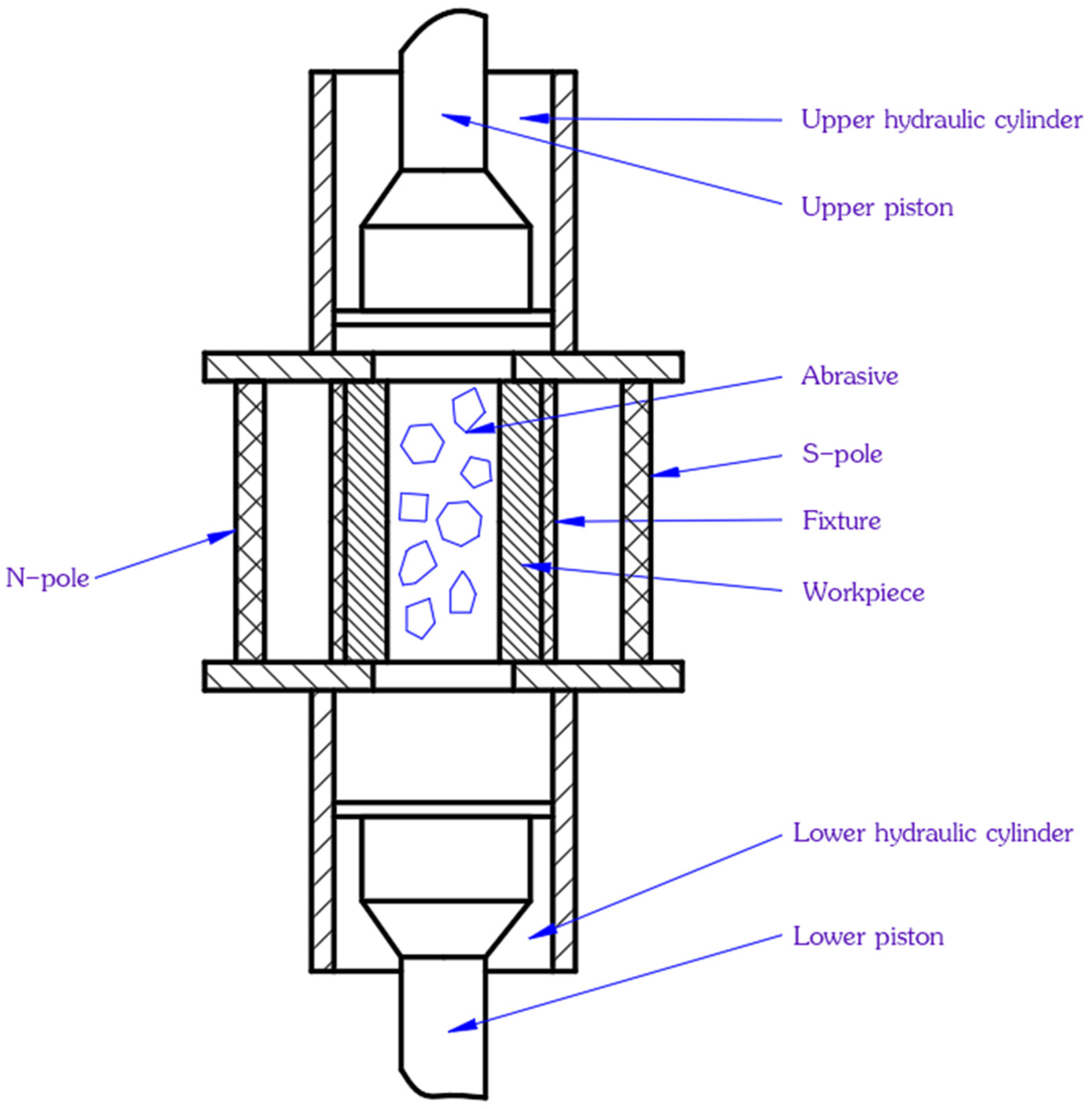
Figure 1. Schematic diagram of the abrasive flow processing of magnetic particles.
Magnetochemistry 08 00035 g001
Figure 2. Variation diagram of abrasive flow polishing fluid.
Magnetochemistry 08 00035 g002
Figure 3. Dimensional watershed diagram of the five-hole nozzle.
Magnetochemistry 08 00035 g003
Figure 4. Five-hole nozzle size and area division diagram.
Magnetochemistry 08 00035 g004
Figure 5. Diagram of grid division of the five-hole nozzle.
Magnetochemistry 08 00035 g005
Figure 6. Five-hole nozzle grid quality inspection drawing.
Magnetochemistry 08 00035 g006
Figure 7. Wall shear force nephogram under different machining parameters.
Magnetochemistry 08 00035 g007aMagnetochemistry 08 00035 g007bMagnetochemistry 08 00035 g007cMagnetochemistry 08 00035 g007d
Figure 8. Physical picture of a five-hole nozzle.
Magnetochemistry 08 00035 g008
Figure 9. Microscopic morphology detection diagram of the original. (a) Pore area; (b) Variable aperture area.
Magnetochemistry 08 00035 g009
Figure 10. Microscopic morphology detection diagram of sample no. 04. (a) Pore area; (b) Variable aperture area.
Magnetochemistry 08 00035 g010
Figure 11. Microscopic morphology detection diagram of sample no. 08. (a) Pore area; (b) Variable aperture area.
Magnetochemistry 08 00035 g011
Figure 12. Microscopic morphology detection diagram of sample no. 12. (a) Pore area; (b) Variable aperture area.
Magnetochemistry 08 00035 g012
Figure 13. Microscopic morphology detection diagram of sample no. 16. (a) Pore area; (b) Variable aperture area.
Magnetochemistry 08 00035 g013
Figure 14. Interaction among factors.
Magnetochemistry 08 00035 g014
Figure 15. Interaction of each factor.
Magnetochemistry 08 00035 g015
Table 1. Orthogonal test table.
Number of GroupsA (mesh)B (Pa·s)C (V)D (MPa)
15000.701
25000.704
35000.7401
45000.7404
55001.1601
65001.1604
75001.16401
85001.16404
912000.701
1012000.704
1112000.7401
1212000.7404
1312001.1601
1412001.1604
1512001.16401
1612001.16404
Table 2. Wall shear force comparison table of each area of the five-hole nozzle (groups 1–15).
ContrastNumber of GroupsWall Shear Force (Pa)
Difference in Macropore AreaArea Difference of Variable CaliberSmall Hole Area Difference
118688.268478,194.4152173,765.3672
2310%310%310%
210.00040.00350.0078
3000
3132.497292.4737649.9414
51.2%1.2%1.2%
410.30522.74756.1055
9000
52000
4000
62223.38282010.44534467.6562
62%2%2%
7227.3898246.5086547.7969
100.2%0.2%0.2%
838688.26878,194.4117173,765.3594
4310%310%310%
9332.497292.4737649.9440
71.2%1.2%1.2%
1030.3052.74576.1015
11000
114223.3822010.43834467.640
82%2%2%
12427.3898246.5086547.7969
120.2%0.2%0.2%
1358497.382676,476.4436169,947.6521
6307%307%307%
1450.00040.00350.0078
7000
1550.09280.83491.8555
13000
Table 3. Wall shear force comparison table of each area of the five-hole nozzle (groups 16–30).
ContrastNumber of GroupsWall Shear Force (Pa)
Difference in Macropore AreaArea Difference of Variable CaliberSmall Hole Area Difference
1550.09280.83491.8555
13000
1660.00080.0070.0156
8000
1761.398412.585927.9688
14000
1878497.38376,476.4471169,947.6602
8307%307%307%
1970.09260.83311.8515
15000
2081.394612.550727.8906
16000
2198715.963478,443.6713174,319.2696
10311%311%311%
2290.00060.00530.0118
11000
2310000
12000
2410252.1712269.53985043.4219
142.2%2.2%2.2%
25118715.962878,443.666174,319.2578
12311%311%311%
2612252.16642269.49765043.3281
162.2%2.2%2.2%
27138496.07776,464.6926169,921.5391
14307%307%307%
28130.00060.00530.0118
15000
29140.00460.04220.0938
16000
30158496.08176,464.7295169,921.6211
16307%307%307%
Table 4. Orthogonal test table.
Test NumberInlet Pressure (MPa)Magnetic Field Intensity (V)Kinematic Viscosity (Pa·s)Abrasive Particle Size (Mesh)
011100.70500
021200.90800
031300.951000
041401.161200
052100.901000
062200.701200
072301.16500
082400.95800
093100.951200
103201.161000
113300.70800
123400.90500
134101.16800
144200.95500
154300.901200
164400.701000
Table 5. Summary of the roughness of the orifice area.
Test NumberOriginal Script0102030405060708
Roughness
(μm)
0.3360.2150.2330.2640.3090.1790.1820.1980.210
Test number0910111213141516
Roughness value (μm)0.1770.1700.1260.1700.1080.0820.1070.075
Table 6. Full-factor experimental design and data testing.
The Experimental SequenceInlet Pressure (MPa)Magnetic Field Intensity (V)Abrasive Particle Size (Mesh)Roughness Value (μm)
122012000.182
24208000.870
32408000.210
44408000.069
544012000.075
642012000.112
724012000.218
82208000.172
Publisher’s Note: MDPI stays neutral with regard to jurisdictional claims in published maps and institutional affiliations.