Abstract
LiFePO₄ (LFP) cathodes are popular due to their safety and cyclic performance, despite limitations in lithium-ion diffusion and conductivity. These can be improved with carbon coating, but further advancements are possible despite commercial success. In this study, we modified the carbon coating layer using sulfur to enhance the electronic conductivity and stabilize the carbon surface layer via two methods: 1-step and 2-step processes. In the 1-step process, sulfur powder was mixed with cellulose followed by heat treatment to form a coating layer; in the 2-step process, an additional coating layer was applied on top of the carbon coating layer. Electrochemical measurements demonstrated that the 1-step sulfur-modified LFP significantly improved the discharge capacity (~152 mAh·g−1 at 0.5 C rate) and rate capability compared to pristine LFP. Raman analyses indicated that sulfur mixed with a carbon source increases the graphitization of the carbon layer. Although the 2-step sulfur modification did not exceed the 1-step process in enhancing rate capability, it improved the storage characteristics of LFP at high temperatures. The residual sulfur elements apparently protected the surface. These findings confirm that sulfur modification of the carbon layer is effective for improving LFP cathode properties, offering a promising approach to enhance the performance and stability of LFP-based lithium-ion batteries.
1. Introduction
The increasing popularity of electric vehicles (EVs) has significantly driven the demand for large-scale lithium-ion batteries (LIBs), fueling the LIB industry. Among the cathodes employed in EV applications, the LiNixCoyMnzO2 (NCM) series are popular owing to their high energy density and excellent rate capability, which support superior acceleration and extended driving ranges [1,2,3,4,5,6,7,8]. However, the recent interest in lithium iron phosphate (LiFePO₄, LFP) cathodes has surged owing to heightened price competition in the EV market and the unstable supply chains for transition metals such as cobalt (Co) and nickel (Ni) [9,10,11,12,13]. LFP cathodes, leveraging the low-cost and abundant iron (Fe), offer several compelling advantages. The stable phase of the material, derived from the robust P-O covalent bond in (PO4)3- polyanion, ensures superior cyclic performance and enhanced safety compared to NCM-based cathodes, making LFP a promising alternative, particularly for cost-effective and reliable solutions amidst fluctuating raw material markets. However, the low lithium-ion diffusion coefficient, ranging only from 10⁻14 to 10⁻16 cm2·s−1, coupled with a poor electronic conductivity of 10⁻⁹ S·cm−1 or lower, significantly hinders the rate capability of LFP [14,15,16,17], which hinders its applicability.
Forming a carbon coating layer on the surface of LFP is effective for improving its deficient rate capability because it can reduce the Li-ion diffusion length to within a particle and facilitate electron transfer [18,19,20,21,22]. Various organic materials such as citric acid, glucose, and polyethylene glycol have been utilized as carbon sources, and sometimes materials such as carbon black or graphene have been directly complexed with the cathode [16,17,18,19,20,21,22]. The commercial success of LFP is largely attributed to the enhanced rate capability due to the carbon coating. However, continuing efforts have been made to modify the carbon to form a more effective carbon layer. Nitrogen doping of carbon to form a more effective electron-transfer carbon coating layer has been used to improve the electrochemical performance of LFPs [23,24,25]. Additionally, F-doped carbon has been utilized to create better carbon coating layers [26]. Metal oxide coatings on LFP have also been explored, occasionally combined with carbon coatings [27,28,29,30,31,32].
In this study, we extended these prior efforts by modifying the carbon coating layer with sulfur. Sulfur has been previously employed to enhance the properties of LFP cathodes focusing on doping these cathodes using lithium sulfide and benzyl disulfide via sol–gel methods [33,34]. However, our study focuses on the modification of the carbon coating layer using sulfur, employing two novel methods. In the first method, sulfur powder is mixed with cellulose, a carbon source, to form a coating layer, referred to as the 1-step process. In this approach, sulfur is used as an additive to improve the properties of the carbon during its formation, while most of the sulfur is expected to evaporate during the heat treatment process; however, a small amount of the remaining sulfur acts as a dopant of LFP. In the second method, referred to as the 2-step process, a carbon coating layer is first formed using cellulose. Subsequently, an additional coating layer is applied in the gas phase using sulfur vapor sublimated from a sulfur source. This approach is anticipated to yield a significantly thin and uniform sulfur layer on top of the carbon coating layer. The additional sulfur-related coating is expected to mitigate the side reactions between the carbon layer and the electrolyte, particularly under high-temperature conditions. To the best of our knowledge, these methods have not been explored thus far. These innovative sulfur-related modifications aim to enhance the electrochemical performance of LFP by improving its rate capability and controlling the side reactions, thereby contributing to the development of more efficient and durable LIBs. To determine the effectiveness of our two approaches for carbon modification using sulfur, the electrochemical properties of pristine LFP (with a carbon coating layer) and sulfur-modified carbon-coated LFP were compared and analyzed using various tools such as Raman spectroscopy, X-ray photoelectron spectroscopy (XPS), transmission electron microscopy (TEM), and time-of-flight secondary ion mass spectrometry (TOF-SIMS).
2. Materials and Methods
In this study, LFP was synthesized using a FePO4 precursor provided by Ecopro BM, and mixed with Li2CO3 (99.9%, Aldrich, St. Louis, MI, USA) and 5 wt.% cellulose (20 µm, Aldrich) to form a carbon coating layer during cathode synthesis. The precursor and Li2CO3 were combined in a molar ratio of 1:1.05. This mixture was then subjected to a milling process using a planetary mono mill (Pulverisette 6, Fritsch, Idar-Oberstein, Germany) at 300 rpm for 3 h with 15 min intervals and a 10 min rest to prevent overheating. The milled mixture was sieved through a 300-mesh sieve. For the 1-step sulfur modification, sulfur (99.998%, Aldrich) was added to the mixed powder in varying amounts (1500, 2000, and 2500 ppm by weight of mixed powder). The mixture was then heat-treated in two stages: first, at 350 °C for 2 h, followed by 700 °C for 6 h under an Ar flow rate of 2 °C/min. This resulted in a 1-step sulfur-modified LFP, while the mixture without the sulfur was the pristine LFP (carbon-coated). A control LFP sample without any carbon coating was also prepared using the same process but without cellulose and sulfur. For the 2-step sulfur modification, pristine LFP was mixed with sulfur (250, 500, 750 ppm by weight of pristine LFP) using a mixer grinder at 30 Hz for 3 min. This mixture was then heat-treated at 300 °C for 4 h in a closed tube under an Ar atmosphere.
The surface morphology after heat treatment was observed using TEM (JEM-2100F, Cs corrector, Japan). The carbon structure was analyzed with a high-resolution Raman spectrometer (Jobin Yvon, LabRam HR Evolution, Japan) to observe the intensity ratio of the disorder peak (D-band at 1342.8 cm⁻1) and the graphitic peak (G band at 1590.7 cm⁻1). XPS (K-Alpha+) was utilized to investigate the carbon/sulfur bonds, and the spectra were analyzed using the Avantage Data System and calibrated with the C-S peak in the S 2p intervals. A TOF-SIMS (TOF-SIMS-5, Bi1+) analysis was also conducted to identify the ionic species. The crystal structures of the differently prepared LFP samples were analyzed via X-ray diffraction (XRD, D8 Discover, Bruker, Billerica, MA, USA).
For the electrochemical testing, a homogeneous slurry was prepared by combining the active cathode material, carbon nanotube (CNTs), Super-P, and polyvinylidene fluoride (PVDF) at a precise weight ratio of 80:10:5:5, utilizing anhydrous N-methyl-2-pyrrolidone (NMP, Aldrich) as the solvent. The resulting slurry was uniformly cast onto aluminum foil, serving as the current collector, and subsequently dried under vacuum conditions at 80 °C for 24 h. The electrochemical performance was evaluated using 2032 coin-type cells, which were assembled with a Li metal anode, a polypropylene (Celgard 2400, USA) separator, and the prepared cathode. For cell testing at the standard conditions of 30 °C, 1M LiPF6 dissolved in EC/DMC (1:1 vol%, Enchem Co., Ltd., Chungbuk, Republic of Korea) was used, while for elevated-temperature testing at 45 °C, 1M LiPF6 in EC/EMC (3:7 vol%, Enchem Co., Ltd.) was utilized. The cells underwent cycling over a voltage range of 2.5–4.2 V at various C rates (0.05, 0.1, 0.3, 0.5, and 1.0 C), with 1 C defined as 150 mA·g⁻1, using a Won A Tech voltammetry system. Impedance measurements were conducted in the charged state after the 1st and 100th cycles at a current density of 150 mA·g⁻1, employing an Ametek VersaSTAT 3 electrochemical workstation. An alternating current voltage of 10 mV was applied over a frequency range of 0.1–100 kHz, and Nyquist plot fitting was performed using the ZSimpWin 3.60 software. The galvanostatic intermittent titration technique (GITT) was utilized to evaluate the Li-ion diffusion characteristics following the charge–discharge cycling, intermittently applying a pulse current of 0.1 C for 10 min. The Li+ ion-diffusion coefficient (DLi+) was calculated using the following equation:
where represents the pulse duration (600 s), denotes the molecular weight of the active material, signifies the molar volume of the active material, S denotes the contact area between the electrolyte and the active material, represents the transient voltage change, and signifies the steady-state voltage change.
3. Results and Discussion
To assess the changes in the electrochemical properties resulting from the 1-step and 2-step sulfur modification processes, the charge–discharge profiles and discharge capacities of the sulfur-modified LFP were compared to those of the pristine LFP. The results, measured at 30 °C, are shown in Figure 1 and Table 1.
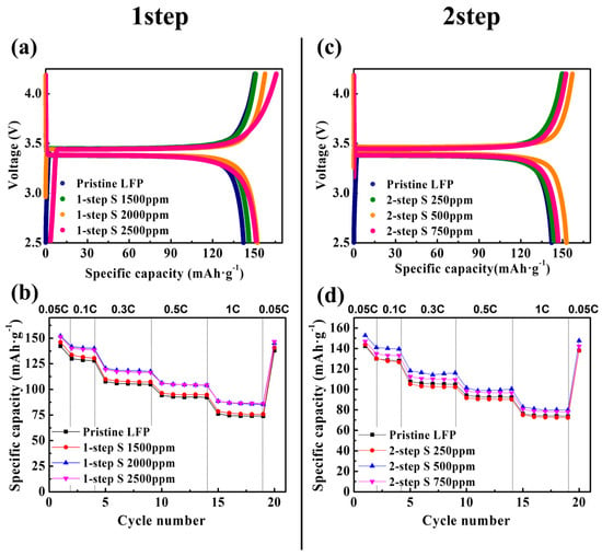
Figure 1.
(a) Initial charge–discharge profiles and (b) discharge capacities at 0.05, 0.1, 0.3, 0.5, and 1 C rates for the pristine LFP and 1-step sulfur-modified LFPs. (c) Initial charge–discharge profiles and (d) discharge capacities at 0.05, 0.1, 0.3, 0.5, and 1 C rates for the pristine LFP and 2-step sulfur-modified LFPs.

Table 1.
Discharge capacities of pristine LFP and sulfur-modified LFP (1-step and 2-step processes) at 0.05, 0.1, 0.3, 0.5, and 1 C rates, and their capacity retentions (measured at 30 °C).
The pristine LFP, containing a carbon coating layer derived from a cellulose source (5wt.%), served as the control. As illustrated in Figure 1a,b, despite certain variations depending on the amount of sulfur source used in the sulfur modification process (adjusted to 1500, 2000, and 2500 ppm), the 1-step sulfur-modified LFP exhibited a notable increase in the discharge capacity. In particular, the best performance was achieved with a sulfur source with a concentration of 2000 ppm. The discharge capacities of the pristine LFP were approximately 142 (0.05 C), 130 (0.1 C), 108 (0.3 C), 94 (0.5 C), and 76 (1 C) mAh·g−1, as summarized in Table 1. Conversely, the 2000 ppm 1-step sulfur-modified LFP demonstrated improved capacities of approximately 152 (0.05 C), 142 (0.1 C), 121 (0.3 C), 106 (0.5 C), and 89 (1 C) mAh·g−1. Furthermore, the rate characteristics also demonstrated a significant improvement with the 1-step sulfur modification. The capacity retention, defined as the percentage of capacity at a 1 C rate compared to that at a 0.05 C rate, improved from 53.6% for pristine LFP to over 58% with the 2000 and 2500 ppm 1-step sulfur modification. Figure S1 and Table S1 (Supplemental Information) present the electrochemical performance of the 1-step sulfur-modified LFP measured at 45 °C, demonstrating a significant increase in the discharge capacity and an improvement in the rate capability, which is consistent with the results at 30 °C. Given that the carbon coating sources for both the pristine and 1-step sulfur-modified LFPs were identical (5 wt.% cellulose), the 1-step sulfur modification significantly enhanced the electrochemical properties of LFP.
Figure 1c,d illustrate the electrochemical performance of the 2-step sulfur-modified LFP measured at 30 °C. When 250 ppm of the sulfur source was used, no improvement in the properties was observed compared to the pristine LFP; however, using 500 and 750 ppm of sulfur clearly improved the discharge capacity. Specifically, the apparently optimal 500 ppm 2-step sulfur-modified LFP exhibited capacities of approximately 153 (0.05 C), 141 (0.1 C), 118 (0.3 C), 102 (0.5 C), and 83 (1 C) mAh·g−1, which were higher than those of the pristine LFP (Table 1). As shown in Figure S2 and Table S1 (Supplemental Information), the 2-step sulfur modification also effectively increased the discharge capacity of the LFP measured at 45 °C. However, the rate capability did not improve as significantly as that with the 1-step sulfur modification. As indicated in Table 1 and Table S1, the capacity retention of the 500 ppm 2-step sulfur-modified LFP was 54.3% at 30 °C and 68.2% at 45 °C, indicating an improvement compared to the pristine LFP. However, these values were lower than the capacity retention observed for the 2000 ppm 1-step sulfur-modified LFP, which were 58.1% at 30 °C and 76.0% at 45 °C. This suggests that the 1-step process was more effective than the 2-step process in enhancing the rate capability. Based on these measurements, the optimal amounts of the sulfur source for the 1-step and 2-step sulfur modifications under our experimental conditions were 2000 ppm and 500 ppm, respectively. Hereafter, the 2000 ppm 1-step sulfur-modified LFP will be referred to as the “1-step SLFP” and the 500 ppm 2-step sulfur-modified LFP will be referred to as the “2-step SLFP,” both of which will be compared to the pristine LFP.
Figure S3 compares the XRD patterns of the 1-step and 2-step sulfur-modified SLFPs with that of the pristine LFP. The similarity in the peaks among these samples indicates that the sulfur modification process did not significantly alter the LFP phase. Table 2 summarizes the lattice parameters of the pristine LFP, 1-step SLFP, and 2-step SLFP, as determined by the Rietveld refinement of their XRD patterns. The lattice parameters demonstrated slight variations among the samples. Although the difference between the pristine LFP and 2-step SLFP was minimal, the lattice volume of the 1-step SLFP (291.35 Å3) was greater than that of the pristine LFP (290.85 Å), and more pronounced changes in the lattice parameters were observed. This suggests that the high-temperature heat treatment process for the 1-step SLFP may have resulted in the doping of certain sulfur elements into the LFP structure, causing the changes observed in the lattice parameters. Conversely, the sulfur elements for the 2-step SLFP were supplied at a lower temperature of 300 °C after the carbon coating layer was already formed. Consequently, the sulfur was likely positioned on the surface rather than being doped into the LFP structure, making any doping effect unlikely. The surface coating layer was examined via a TEM analysis, as illustrated in Figure 2.

Table 2.
Lattice parameters obtained from XRD patterns of the pristine LFP, 1-step sulfur-modified SLFP, and 2-step sulfur-modified SLFP via Rietveld refinement.
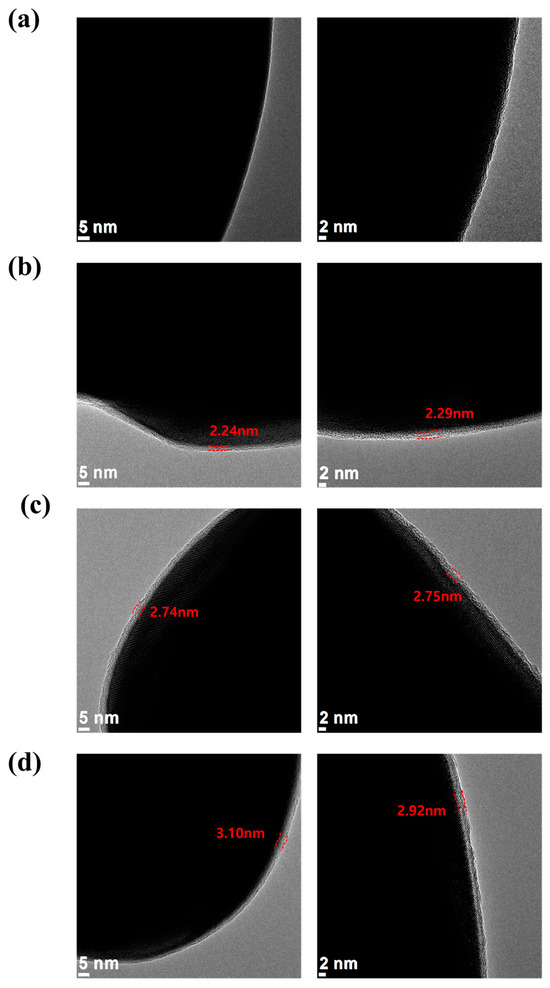
Figure 2.
TEM images of the (a) carbon-uncoated LFP, (b) pristine LFP (carbon-coated), (c) 1-step sulfur-modified SLFP, and (d) 2-step sulfur-modified SLFP.
For comparison, TEM images of the carbon-uncoated LFP were also captured (Figure 2a), which did not present a distinct surface layer. Conversely, the pristine LFP (carbon-coated) exhibited a clearly defined 2–3 nm thick surface layer, which was identified as the carbon coating layer (Figure 2b). Both the 1-step and 2-step sulfur-modified SLFPs demonstrated a similar thickness of the carbon coating layer and no significant changes were observed owing to the sulfur modification (Figure 2c,d).
Figure 3 compares the Raman spectra of the 1-step and 2-step sulfur-modified SLFP with that of the pristine LFP. Raman spectroscopy is an effective technique for characterizing the carbon structure (including disorders and crystallite formation) of the coating layer owing to the strong scattering properties of carbon, with two E2g modes, predicted to be Raman active. The carbon structure of the coating layer significantly influences the LFP properties, as a higher proportion of graphitic carbon than the disordered carbon enhances the electronic conductivity. Figure 3 demonstrates broad peaks located at approximately 1342.8 and 1590.7 cm⁻1, which indicate the D and G bands of the carbon coating, respectively. The extent of graphitization and its ratio to disordered carbon is typically characterized by the ID/IG (intensity ratio of D and G bands) ratio in the Raman spectrum [35,36,37]. As shown in Figure 3a,b, the intensity of the G band in the Raman spectrum of the 1-step SLFP is slightly larger than that of the pristine sample.
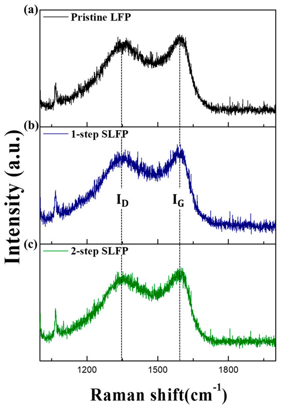
Figure 3.
Raman spectra of the (a) pristine LFP, (b) 1-step sulfur-modified SLFP, and (c) 2-step sulfur-modified SLFP.
The calculated ID/IG ratio for the 1-step SLFP (0.90) was relatively lower than that of the pristine sample (0.95), suggesting that the 1-step sulfur modification increased the proportion of graphitic carbon compared to the disordered carbon, resulting in an improved electronic conductivity. The improved rate capability observed in Figure 1 with the 1-step sulfur modification can be attributed to this increased graphitization. The calculated ID/IG ratio for the 2-step SLFP was 0.93, which was also lower than that of the pristine LFP (Figure 3c), indicating that the 2-step sulfur modification process also increased the proportion of graphitic carbon, although to a lesser extent than that of the 1-step sulfur modification. The relatively small proportion of graphite carbon likely caused the 2-step sulfur modification to be relatively less successful compared to the 1-step sulfur modification in enhancing the rate capability.
The Raman analysis confirmed that the carbon structure was altered to a certain extent via sulfur modification. Additionally, the sulfur element remaining in the carbon coating layer may have played a crucial role in protecting the cathode interface from the electrolyte. Given that both the 1-step and 2-step processes involved heat treatment, the sulfur element may have been reduced compared to the initial amount supplied. XPS and TOF-SIMS analyses were conducted to verify the amount of sulfur retained in the surface coating layer. As shown in Figure S4 (Supplemental Information), distinguishing the sulfur-related peaks of the pristine LFP and 1-step SLFP in the XPS spectra was challenging. However, in the 2-step SLFP spectrum, a faint sulfur-related peak was observed at approximately 162–165 eV, indicating that the 2-step SLFP contained more residual sulfur than the 1-step SLFP; however, the peak intensity was too low for a definitive comparison between the samples. This low intensity was likely owing to the minimal amount of the sulfur-containing carbon layer on the cathode surface. Therefore, sulfur-modified carbon samples (excluding the cathode) were prepared utilizing the same method used for the 2-step SLFP and were analyzed via XPS. As shown in Figure 4d, distinct peaks related to the C-S-C bond near 163 and 164.2 eV were identified, indicating that the 2-step SLFP with the same sulfur-modified carbon as the coating layer contains a significant amount of sulfur.
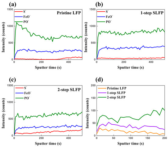
Figure 4.
TOF-SIMS spectra of the surface of (a) pristine LFP, (b) 1-step sulfur-modified SLFP, (c) 2-step sulfur-modified SLFP, and (d) comparison of their S− intensity.
TOF-SIMS was also used for a comparison of the sulfur content on the surface. As shown in Figure 4, the amount of S− detected in the pristine LFP was negligible (Figure 4a). The 1-step SLFP exhibited a slightly higher amount of S− than the pristine LFP, indicating that a certain amount of the sulfur element was retained despite the high-temperature (700 °C) heat treatment (Figure 4b). However, the S− intensity in the 2-step SLFP was relatively higher than in the 1-step SLFP (Figure 4c). The comparison in Figure 4d demonstrates that despite using 2000 ppm of the sulfur source in the 1-step process and only 500 ppm in the 2-step process, the residual sulfur element was greater in the 2-step SLFP, which underwent heat treatment at a lower temperature (300 °C). This suggests that the high-temperature treatment in the 1-step process led to considerable sulfur losses, but it also likely resulted in a certain amount of sulfur doping into the bulk. Additionally, the S element in the 1-step process may have contributed to the increased proportion of graphitic carbon by influencing the carbon formation process.
To verify the change in the interfacial resistance owing to sulfur modification, the impedance of cells containing the pristine LFP, 1-step, and 2-step SLFP were measured. Figure 5 presents the Nyquist plots of the cells after the 1st and 100th cycles. As illustrated, the size of the semicircle in the Nyquist plots significantly decreased with sulfur modification, indicating a decreased impedance. For a more precise analysis, the Nyquist plots were fitted using the equivalent circuit shown in Figure S5 (Supplemental Information), and the obtained impedance values are summarized in Table 3. The Nyquist plots of the cells comprise the bulk resistance (Rb), resistance of the solid-state interface layer formed on the electrode surface (RSEI), charge transfer resistance between the active material particles and the electrolyte (RCT), and the Warburg impedance (W) [38,39]. As shown in Table 3, RCT was reduced by sulfur modification after both the 1st and 100th cycles. Notably, after the 1st cycle, the 1-step SLFP exhibited lower impedance values (~13 Ω) than those of the 2-step SLFP (~30 Ω). The larger amount of carbon, improved carbon structure, and slight sulfur doping effect may have contributed to these low impedance values in the 1-step SLFP. However, after 100 cycles, the impedance values for both the 1-step (~35 Ω) and 2-step SLFP (~35.8 Ω) were nearly similar. Despite being lower than that of the pristine LFP (~54 Ω), the impedance values increased with cycling for both modified samples, with the 2-step SLFP demonstrating a relatively smaller increase in impedance compared to that of the 1-step SLFP, which may be owing to the sulfur element in the carbon coating layer. The 2-step SLFP carbon coating contained relatively more sulfur, which helped reduce the side reactions with the electrolyte during cycling, thus resulting in a relatively smaller increase in the impedance values during cycling.

Figure 5.
Nyquist plots of the cells containing the pristine LFP, 1-step sulfur-modified SLFP, and 2-step sulfur-modified SLFP after (a) 1 cycle and (b) 100 cycles.

Table 3.
Impedance values of the pristine LFP, 1-step sulfur-modified SLFP, and 2-step sulfur-modified SLFP obtained from the Nyquist plots via fitting.
Figure 6 presents the Li-diffusion coefficient (DLi+) values measured using the GITT method (after 100 cycles), as shown in Figure S6a (Supplemental Information). The results indicate an overall improvement in the DLi+ values owing to the sulfur modification. Figure S6b compares the DLi+ values in the plateau range during the discharge process. For the pristine LFP, the DLi+ values ranged from 3.96 × 10⁻¹⁴ to 1.16 × 10⁻¹³ cm2·s−1. Conversely, the 1-step SLFP exhibited DLi+ values ranging from 6.87 × 10⁻¹⁴ to 1.41 × 10⁻¹³ cm2·s−1. Notably, the 2-step SLFP demonstrated slightly higher DLi+ values than those of the 1-step SLFP, ranging from 1.62 × 10⁻¹³ to 1.83 × 10⁻¹³ cm2·s−1. Considering this analysis was performed after 100 cycles, the marginally superior DLi+ values observed for the 2-step SLFP can be attributed to the interfacial protection effect, which enhances the movement of Li ions. This interfacial protection, provided by the sulfur element in the carbon coating layer, likely reduces the side reactions with the electrolyte and facilitates better ionic conductivity.
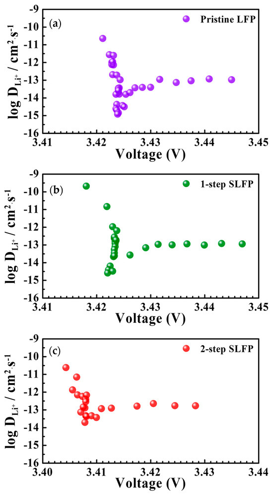
Figure 6.
Li-diffusion coefficient (DLi+) values measured using the GITT method for (a) pristine LFP, (b) 1-step sulfur-modified SLFP, and (c) 2-step sulfur-modified SLFP.
To further elucidate the interface-protection effects of the sulfur modification, we conducted a comparative analysis of the electrochemical properties of the cells containing the LFP samples after storage at 60 °C. The elevated temperature accelerated the side reactions at the interface, providing a clear platform to evaluate the interface stabilization imparted by the sulfur modification. As shown in Figure 7a–c, the initial charge–discharge profiles were recorded for the cells stored at 60 °C for 7, 10, and 14 days, respectively.
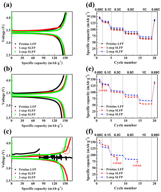
Figure 7.
Charge–discharge profiles of the pristine LFP, 1-step sulfur-modified SLFP, and 2-step sulfur-modified SLFP after storage for (a) 7 days, (b) 10 days, and (c) 14 days. Discharge capacities at 0.05, 0.1, 0.3, 0.5, and 1 C rates for the pristine LFP, 1-step sulfur-modified SLFP, and 2-step sulfur-modified SLFP after storage for (d) 7 days, (e) 10 days, and (f) 14 days.
After 7 days of storage, the differences among the samples were minimal. However, after 10 days, the pristine LFP exhibited a noticeable decrease in capacity, whereas both the 1-step and 2-step SLFP samples demonstrated a minimal deviation from their 7-day performance, indicating enhanced stability. The distinction became more pronounced after 14 days, when the pristine LFP cells ceased to function properly, whereas the 2-step SLFP cells continued to charge and discharge normally with only a slight capacity loss. Conversely, the 1-step SLFP demonstrated a certain amount of degradation; although operational, it exhibited irregularities in its charge/discharge curves (marked with a red circle). Figure 7d–f demonstrate the discharge capacities at 0.05, 0.1, 0.3, 0.5, and 1 C rates post-storage at 60 °C, with the corresponding data summarized in Table 4.

Table 4.
Discharge capacities of the pristine LFP and sulfur-modified LFP (1-step and 2-step processes) at 0.05, 0.1, 0.3, 0.5, and 1 C rates measured after storage for 7, 10, and 14 days at 60 °C.
After 7 days, all the cells cycled normally. However, following 10 days of storage, the cell with pristine LFP failed to cycle at a 0.1 C rate. The 1-step SLFP cells remained functional across all C rates, but the capacity retention representing the rate capability significantly diminished to ~39% compared to the 7-day mark (~44%), indicating substantial deterioration. Conversely, the 2-step SLFP cells exhibited a smaller reduction in capacity retention, from ~50% (7 days of storage) to 46% (10 days of storage), and maintained a relatively stable operation. After 14 days, the pristine LFP sample entirely ceased to function, whereas the 1-step SLFP failed to operate at a rate of 0.5 C. Conversely, the 2-step SLFP managed to maintain the performance until it eventually stopped running at a rate of 1 C. These findings indicate that the 2-step sulfur modification process significantly enhances the cathode protection against side reactions with the electrolyte. This improved performance demonstrates the superior stability of sulfur-modified carbon via vaporized sulfur. Although the 1-step sulfur modification also demonstrated improved stability during the storage test compared to the pristine LFP, it was less effective than the 2-step approach. Therefore, the 2-step sulfur modification process offers superior protection against interface side reactions, rendering it more effective in stabilizing the cathode under elevated temperature conditions. Figure 8 schematically summarizes the effects of the 1-step and 2-step sulfur modifications.
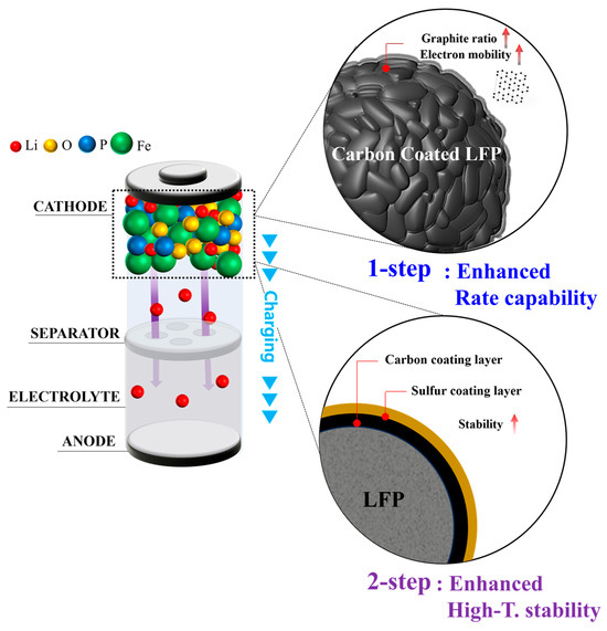
Figure 8.
Schematic summarization of the 1-step and 2-step sulfur modification effects.
4. Conclusions
In this study, sulfur modification of the carbon layer was introduced to enhance the performance of the carbon coating layer for LFP cathodes. Two methods were explored: a 1-step process and a 2-step process. In the 1-step process, sulfur powder was mixed with cellulose followed by heat treatment to form a coating layer, with the sulfur element expected to improve the properties of the carbon coating layer during the heating process. In the 2-step process, an additional coating layer was applied on top of the carbon coating layer using vaporized sulfur during a low-temperature (300 °C) heat treatment, aiming to improve the high-temperature stability of the surface layer. The 1-step sulfur-modified LFP exhibited an enhanced discharge capacity and rate capability compared to the pristine LFP. Under optimal conditions, the sample exhibited a discharge capacity of approximately 152 mAh/g at a 0.05 C rate, with a capacity retention of around 58%, where capacity retention is defined as the percentage of capacity at a 1 C rate compared to that at 0.05 C. Raman spectroscopy indicated increased graphitization in the 1-step SLFP, which enhanced the electronic conductivity. Although the 2-step sulfur modification did not improve the rate capability as effectively as the 1-step process, it better maintained the electrochemical properties during storage at high temperatures (60 °C). TOF-SIMS analyses confirmed the sulfur retention in the surface coating layer, indicating more sulfur retention with the 2-step SLFP owing to the treatment at a lower temperature. The sulfur elements on the surface are expected to enhance the stability of the LFP at high temperatures. Impedance measurements indicated a reduced impedance for the sulfur-modified LFP, and the GITT method confirmed improved Li-diffusion coefficient values owing to the sulfur modification. Based on these results, sulfur modification significantly enhances the electrochemical performance and stability of LFP cathodes, offering a promising solution for improving the performance of LIBs based on LFP. Table 5 provides a comparative summary of the results from this study alongside previous studies focusing on carbon coatings. The data highlight that the current work demonstrates highly competitive properties, with the results suggesting that sulfur modification offers a significant advantage over conventional carbon coatings. It is hoped that further research in this area will continue to explore the potential of sulfur modification, potentially leading to even greater performance improvements for LFP-based LIBs in the future.

Table 5.
Discharge capacities of carbon-coated LFP obtained from the previous study.
Supplementary Materials
The following supporting information can be downloaded at: https://www.mdpi.com/article/10.3390/batteries10100348/s1. Figure S1: (a) Initial charge–discharge profiles and (b) discharge capacities at 0.05, 0.1, 0.3, 0.5, and 1 C rates for the pristine LFP and 1-step sulfur-modified LFPs measured at 45 °C. Figure S2: (a) Initial charge–discharge profiles and (b) discharge capacities at 0.05, 0.1, 0.3, 0.5, and 1 C rates for the pristine LFP and 2-step sulfur-modified LFPs measured at 45 °C. Figure S3: XRD patterns of the pristine LFP, 1-step sulfur-modified SLFP, and 2-step sulfur-modified SLFP. Figure S4: XPS spectra of the (a) pristine LFP, (b) 1-step sulfur-modified SLFP, (c) 2-step sulfur-modified SLFP, and (d) sulfurized carbon using the 2-step process (the same carbon:sulfur ratio as the 2-step sulfur-modified SLFP was used). Figure S5: (a) Equivalent circuit for fitting the Nyquist plots and (b) fitting example using Rb, RSEI, Rct, and W. Figure S6: (a) Measurement profile for the GITT method and (b) comparison of the Li-diffusion coefficient (DLi+) values for the pristine LFP, 1-step sulfur-modified SLFP, and 2-step sulfur-modified SLF in the plateau region. Table S1: Discharge capacities of the pristine LFP and sulfur-modified LFP (1-step and 2-step processes) at 0.05, 0.1, 0.3, 0.5, and 1 C rates, and their capacity retentions (measured at 45 °C). Table S2: Lattice parameters obtained from the XRD patterns of the pristine LFP, 1-step sulfur-modified SLFP, and 2-step sulfur-modified SLFP via Rietveld refinement.
Author Contributions
Conceptualization, investigation, data curation, writing—original draft preparation, S.-h.K.; writing—review and editing, supervision, funding acquisition, Y.J.P. All authors have read and agreed to the published version of the manuscript.
Funding
This work was supported by the Materials and Components Technology Development Program (grant No. 20024249) funded By the Ministry of Trade, Industry and Energy (MOTIE, Republic of Korea), and by the National Research Foundation of Korea (NRF), grant funded by the Korean government (MSIT, No. 2023R1A2C1003330).
Data Availability Statement
Data are contained within the article.
Acknowledgments
This work was supported by the Materials and Components Technology Development Program (grant No. 20024249) funded By the Ministry of Trade, Industry and Energy (MOTIE, Republic of Korea), and by the National Research Foundation of Korea (NRF), grant funded by the Korean government (MSIT, No. 2023R1A2C1003330).
Conflicts of Interest
The authors declare no conflicts of interest.
References
- Huang, J.; Fan, Z.; Xu, C.; Jiang, F.; Feng, X. Experimental investigation of thermal runaway characteristics of large-format Li(Ni0.8Co0.1Mn0.1)O2 Battery under Different Heating Powers and Areas. Batteries 2024, 10, 241. [Google Scholar] [CrossRef]
- Das, D.; Manna, S.; Puravankara, S. Electrolytes, Additives and Binders for NMC cathodes in Li-ion batteries—A review. Batteries 2023, 9, 193. [Google Scholar] [CrossRef]
- Panda, P.K.; Cho, T.S.; Hsieh, C.-T.; Yang, P.C. Cobalt- and Copper-Doped NASICON-Type LATP Polymer Composite Electrolytes Enabling Lithium Titania Electrode for Solid-State Lithium Batteries with High-Rate Capability and Excellent Cyclic Performance. J. Energy Storage 2024, 95, 112559. [Google Scholar] [CrossRef]
- Joo, M.J.; Kim, M.; Chae, S.; Ko, M.; Park, Y.J. Additive-derived surface modification of cathodes in all-solid-state batteries: The effect of lithium difluorophosphate- and lithium Difluoro(Oxalato)Borate-derived coating layers. ACS Appl. Mater. Interfaces 2023, 15, 59389–59402. [Google Scholar] [CrossRef]
- Ji, Y.J.; Noh, S.; Seong, J.Y.; Lee, S.; Park, Y.J. Li3BO3-Li3PO4 Composites for Efficient Buffer Layer of Sulphide-Based All-Solid-State Batteries. Batteries 2024, 9, 292. [Google Scholar] [CrossRef]
- Madaoui, S.; Vinassa, J.M.; Sabatier, J.; Guillemard, F. An electrothermal model of an NMC lithium-ion prismatic battery cell for temperature distribution assessment. Batteries 2023, 9, 478. [Google Scholar] [CrossRef]
- Joo, M.J.; Park, Y.J. Stabilizing Li2O-based Cathode /Electrolyte interfaces through succinonitrile addition. J. Electrochem. Sci. Technol. 2023, 14, 231–242. [Google Scholar] [CrossRef]
- Hawley, W.B.; Li, M.; Li, J. Room-temperature eutectic synthesis for upcycling of cathode materials. Batteries 2023, 9, 498. [Google Scholar] [CrossRef]
- Ramasubramanian, B.; Sundarrajan, S.; Chellappan, V.; Reddy, M.V.; Ramakrishna, S.; Zaghib, K. Recent development in carbon-LiFePO4 cathodes for lithium-ion batteries: A mini review. Batteries 2022, 8, 133. [Google Scholar] [CrossRef]
- Mohanty, D.; Chang, M.J.; Hung, I.M. The effect of different amounts of conductive carbon material on the electrochemical performance of the LiFePO4 cathode in Li-ion batteries. Batteries 2023, 9, 515. [Google Scholar] [CrossRef]
- Wu, K.; Hu, N.; Wang, S.; Geng, Z.; Deng, W. Enhancing performance of LiFePO4 battery by using a novel gel composite polymer electrolyte. Batteries 2023, 9, 51. [Google Scholar] [CrossRef]
- Zhang, W.J. Structure and performance of LiFePO4 cathode materials: A review. J. Power Sources 2011, 196, 2962–2970. [Google Scholar] [CrossRef]
- Chen, S.P.; Lv, D.; Chen, J.; Zhang, Y.H.; Shi, F.N. Review on defects and modification methods of LiFePO4 Cathode material for lithium-ion batteries. Energy Fuels 2022, 36, 1232–1251. [Google Scholar] [CrossRef]
- Prosini, P.P.; Lisi, M.; Jane, D.; Pasquali, M. Determination of the Diffusion Coefficient of LiFePO4. Solid State Ionics 2002, 148, 45–51. [Google Scholar] [CrossRef]
- Amin, R.; Balaya, P.; Maier, J. Anisotropy of electronic and ionic transport in LiFePO4 single crystals. Electrochem. Solid State Lett. 2007, 10, 13–16. [Google Scholar] [CrossRef]
- Wang, J.; Sun, X. Understanding and recent development of carbon coating on LiFePO4 cathode materials for lithium-ion batteries. Energy Environ. Sci. 2012, 5, 5163–5185. [Google Scholar] [CrossRef]
- Moon, H.; Kim, D.; Park, G.; Shin, K.; Cho, Y.; Gong, C.; Lee, Y.S.; Nam, H.; Hong, S.; Choi, N.S. Balancing ionic and electronic conduction at the LiFePO4 cathode–electrolyte interface and regulating solid electrolyte interphase in lithium-ion batteries. Adv. Funct. Mater. 2024, 34, 2403261. [Google Scholar] [CrossRef]
- Ni, H.; Liu, J.; Fan, L.Z. Carbon-coated LiFePO4-porous carbon composites as cathode materials for lithium ion batteries. Nanoscale 2013, 5, 2164–2168. [Google Scholar] [CrossRef] [PubMed]
- Wang, C.; Yuan, X.; Tan, H.; Jian, S.; Ma, Z.; Zhao, J.; Wang, X.; Chen, D.; Dong, Y. Three-dimensional carbon-coated LiFePO4 cathode with improved Li-ion battery performance. Coatings 2021, 11, 1137. [Google Scholar] [CrossRef]
- Qi, M.; Liu, Y.; Xu, M.; Feng, M.; Gu, J.; Liu, Y.; Wang, L. Improved electrochemical performances of carbon-coated LiFePO4 microspheres for Li-ion battery cathode. Mater. Res. Express 2019, 6, 115520. [Google Scholar] [CrossRef]
- Nien, Y.H.; Carey, J.R.; Chen, J.S. Physical and electrochemical properties of LiFePO4/C composite cathode prepared from various polymer-containing precursors. J. Power Sources 2009, 193, 822–827. [Google Scholar] [CrossRef]
- Mathur, P.; Shih, J.Y.; Li, Y.J.J.; Hung, T.F.; Thirumalraj, B.; Ramaraj, S.K.; Jose, R.; Karuppiah, C.; Yang, C.C. In situ metal organic framework (ZIF-8) and mechanofusion-assisted MWCNT coating of LiFePO4/C composite material for lithium-ion batteries. Batteries 2023, 9, 182. [Google Scholar] [CrossRef]
- Yoon, S.; Liao, C.; Sun, X.G.; Bridges, C.A.; Unocic, R.R.; Nanda, J.; Dai, S.; Paranthaman, M.P. Conductive surface modification of LiFePO4 with nitrogen-doped carbon layers for lithium-ion batteries. J. Mater. Chem. 2012, 22, 4611–4614. [Google Scholar] [CrossRef]
- Yang, J.; Wang, J.; Li, X.; Wang, D.; Liu, J.; Liang, G.; Gauthier, M.; Li, Y.; Geng, D.; Li, R.; et al. Hierarchically porous LiFePO4/nitrogen-doped carbon nanotubes composite as a cathode for lithium ion batteries. J. Mater. Chem. 2012, 22, 7537–7543. [Google Scholar] [CrossRef]
- Zhang, J.; Nie, N.; Liu, Y.; Wang, J.; Yu, F.; Gu, J.; Li, W. Boron and Nitrogen Codoped carbon layers of LiFePO4 improve the high-rate electrochemical performance for lithium ion batteries. ACS Appl. Mater. Interfaces 2015, 7, 20134–20143. [Google Scholar] [CrossRef] [PubMed]
- Wang, X.; Feng, Z.; Hou, X.; Liu, L.; He, M.; He, X.; Huang, J.; Wen, Z. Fluorine doped carbon coating of LiFePO4 as a cathode material for lithium-ion batteries. Chem. Eng. J. 2020, 379, 122371. [Google Scholar] [CrossRef]
- Cho, J.; Kim, Y.J.; Park, B. Novel LiCoO2 cathode material with Al2O3 coating for a Li ion cell. Chem. Mater. 2000, 12, 3788–3791. [Google Scholar] [CrossRef]
- Chang, H.H.; Chang, C.C.; Su, C.Y.; Wu, H.C.; Yang, M.H.; Wu, N.L. Effects of TiO2 coating on high-temperature cycle performance of LiFePO4-based lithium-ion batteries. J. Power Sources 2008, 185, 466–472. [Google Scholar] [CrossRef]
- Cui, Y.; Zhao, X.; Guo, R. Enhanced electrochemical properties of LiFePO4 cathode material by CuO and carbon co-coating. J. Alloys Compd. 2010, 490, 236–240. [Google Scholar] [CrossRef]
- Cui, Y.; Zhao, X.; Guo, R. High rate electrochemical performances of nanosized ZnO and carbon co-coated LiFePO4 cathode. Mater. Res. Bull. 2010, 45, 844–849. [Google Scholar] [CrossRef]
- Cho, J.; Kim, Y.J.; Kim, T.J.; Park, B. Zero-strain intercalation cathode for rechargeable Li-ion cell. Angew. Chem. Int. Ed. Engl. 2001, 40, 3367–3369. [Google Scholar] [CrossRef] [PubMed]
- Zhao, S.X.; Ding, H.; Wang, Y.C.; Li, B.H.; Nan, C.W. Improving rate performance of LiFePO4 cathode materials by hybrid coating of nano-Li3PO4 and carbon. J. Alloys Compd. 2013, 566, 206–211. [Google Scholar] [CrossRef]
- Lee, S.B.; Cho, S.H.; Aravindan, V.; Kim, H.S.; Lee, Y.S. Improved cycle performance of sulfur doped LiFePO4 material at high temperatures. Koreascience 2009, 30, 2223–2226. [Google Scholar] [CrossRef][Green Version]
- Xu, D.; Wang, P.; Shen, B. Synthesis and characterization of sulfur-doped carbon decorated LiFePO4 nanocomposite as high performance cathode material for lithium-ion batteries. Ceram. Int. 2016, 42, 5331–5338. [Google Scholar] [CrossRef]
- Wilcox, J.D.; Doeff, M.M.; Marcinek, M.; Kostecki, R. Factors influencing the quality of carbon coatings on LiFePO4. J. Electrochem. Soc. 2007, 154, A389–A395. [Google Scholar] [CrossRef]
- Ait Salah, A.; Mauger, A.; Zaghib, K.; Goodenough, J.B.; Ravet, N.; Gauthier, M.; Gendron, F.; Julien, C.M. Reduction Fe3+ of Impurities in LiFePO4 from Pyrolysis of Organic Precursor Used for Carbon Deposition. J. Electrochem. Soc. 2006, 153, A1692–A1701. [Google Scholar] [CrossRef]
- Doeff, M.M.; Wilcox, J.D.; Kostecki, R.; Lau, G. Optimization of carbon coatings on LiFePO4. J. Power Sources 2006, 163, 180–184. [Google Scholar] [CrossRef]
- Bao, S.J.; Liang, Y.Y.; Li, H.L. Synthesis and electrochemical properties of LiMn2O4 by microwave-assisted sol-gel method. Mater. Lett. 2005, 59, 3761–3765. [Google Scholar] [CrossRef]
- Nara, H.; Morita, K.; Mukoyama, D.; Yokoshima, T.; Momma, T.; Osaka, T. Impedance analysis of LiNi1/3Mn1/3Co1/3O2 cathodes with different secondary-particle size distribution in lithium-ion battery. Electrochim. Acta 2017, 241, 323–330. [Google Scholar] [CrossRef]
- Xia, J.; Zhu, F.; Wang, G.; Wang, L.; Meng, Y.; Zhang, Y. Synthesis of LiFePO4/C using ionic liquid as carbon source for lithium ion batteries. Solid State Ion. 2017, 308, 133–138. [Google Scholar] [CrossRef]
- Guo, F.; Huang, X.; Li, Y.; Zhang, S.; He, X.; Liu, J.; Yu, Z.; Li, F. In Situ Low-Temperature Carbonization Capping of LiFePO4 with Coke for Enhanced Lithium Battery Performance. Molecules 2023, 28, 6083. [Google Scholar] [CrossRef] [PubMed]
- Fei, H.; Peng, Z.; Yang, Y.; Li, L.; Raji, A.R.O.; Samuel, E.L.G.; Tour, J.M. LiFePO4 nanoparticles encapsulated in graphene nanoshells for high-performance lithium-ion battery cathodes. Chem. Commun. 2014, 50, 7117–7119. [Google Scholar] [CrossRef] [PubMed]
- Pratheeksha, P.M.; Rajeshwari, J.S.; Daniel, P.J.; Rao, T.N.; Anandan, S. Investigation of In-Situ Carbon Coated LiFePO4 as a Superior Cathode Material for Lithium Ion Batteries. J. Nanosci. Nanotechnol. 2018, 19, 3002–3011. [Google Scholar] [CrossRef] [PubMed]
- Wu, S.; Luo, E.; Ouyang, J.; Lu, Q.; Zhang, X.; Wei, D.; Han, W.K.; Xu, X.; Wei, L. Tuning the graphitization of the carbon coating layer on LiFePO4 Enables Superior Properties. Int. J. Electrochem. Sci. 2024, 19, 100450. [Google Scholar] [CrossRef]
- Chen, C.; Luo, C.; Jin, Y.; Li, J.; Zhao, Q.; Yang, W. Short-Process Spray-Drying Synthesis of Lithium Iron Phosphate@Carbon Composite for Lithium-Ion Batteries. ACS Sustain. Chem. Eng. 2024, 12, 14077–14086. [Google Scholar] [CrossRef]
Disclaimer/Publisher’s Note: The statements, opinions and data contained in all publications are solely those of the individual author(s) and contributor(s) and not of MDPI and/or the editor(s). MDPI and/or the editor(s) disclaim responsibility for any injury to people or property resulting from any ideas, methods, instructions or products referred to in the content. |
© 2024 by the authors. Licensee MDPI, Basel, Switzerland. This article is an open access article distributed under the terms and conditions of the Creative Commons Attribution (CC BY) license (https://creativecommons.org/licenses/by/4.0/).