Article

Operando Fabricated Quasi-Solid-State Electrolyte Hinders Polysulfide Shuttles in an Advanced Li-S Battery

1
Davidson School of Chemical Engineering, Purdue University, West Lafayette, IN 47907, USA
2
School of Materials Engineering, Purdue University, West Lafayette, IN 47907, USA
*
Authors to whom correspondence should be addressed.
These authors contributed equally to this work.
Batteries 2024, 10(10), 349; https://doi.org/10.3390/batteries10100349
Submission received: 26 July 2024 / Revised: 19 September 2024 / Accepted: 29 September 2024 / Published: 1 October 2024
(This article belongs to the Special Issue Electrolytes for Solid State Batteries—2nd Edition)

Abstract

:
Lithium-sulfur (Li-S) batteries are a promising option for energy storage due to their theoretical high energy density and the use of abundant, low-cost sulfur cathodes. Nevertheless, several obstacles remain, including the dissolution of lithium polysulfides (LiPS) into the electrolyte and a restricted operational temperature range. This manuscript presents a promising approach to addressing these challenges. The manuscript describes a straightforward and scalable in situ thermal polymerization method for synthesizing a quasi-solid-state electrolyte (QSE) by gelling pentaerythritol tetraacrylate (PETEA), azobisisobutyronitrile (AIBN), and a dual salt lithium bis(trifluoromethanesulfonyl)imide (LiTFSI) and lithium nitrate (LiNO3)-based liquid electrolyte. The resulting freestanding quasi-solid-state electrolyte (QSE) effectively inhibits the polysulfide shuttle effect across a wider temperature range of −25 °C to 45 °C. The electrolyte’s ability to prevent LiPS migration and cluster formation has been corroborated by scanning electron microscopy (SEM) and Raman spectroscopy analyses. The optimized QSE composition appears to act as a physical barrier, thereby significantly improving battery performance. Notably, the capacity retention has been demonstrated to reach 95% after 100 cycles at a 2C rate. Furthermore, the simple and scalable synthesis process paves the way for the potential commercialization of this technology.

1. Introduction

The global focus is now on progressing electric vehicle (EV) technology, which has strict performance requirements. There are several categories of batteries that currently are used for EVs, including lead-acid batteries, nickel metal hydride batteries, and lithium-ion (Li-ion) batteries [1]. From these options, Li-ion batteries are generally preferred due to their lower self-discharge rate, higher energy density, and longer cycle life [1,2]. Li-ion technology suffers from limitations compared to an internal combustion engine in theoretical maximum driving range and price and has therefore failed to fully replace it [3]. The cost of Li-ion batteries is driven by the high price of raw materials, such as cobalt [4,5]. Other abundant and cheap battery technology options, such as sodium and potassium, have shown promise but are far behind in terms of cycling performance and energy density [6,7]. Lithium-Sulfur (Li-S) technologies are being explored as the next step in energy storage technology due to the low cost and abundance of sulfur and the high electrochemical activity of sulfur, which can accept about two electrons per atom at about 2.1 V vs. Li/Li+ [8]. Sulfur has a high theoretical capacity of 1675 mAh g−1, resulting in an impressive energy density of 2600 Wh kg−1 or 2800 Wh/L−1 [9]. This advantage makes them highly suitable for EV applications as it enables a driving range that is comparable to conventional vehicles as opposed to current Li-ion batteries [10]. Additionally, sulfur, a key component, is abundant, affordable, and eco-friendly, further enhancing the economic and environmental appeal of these batteries with a ~30% reduction in overall greenhouse gas emissions for Li-S batteries when compared to Li-ion [10]. However, their current state-of-the-art faces challenges that limit their commercialization, such as capacity loss, a narrow temperature range, unscalable manufacturing methods, and a gap from theoretical capacity. This gap is caused by side reactions and mechanics associated with the redox reaction at the sulfur cathode. During the charge-discharge process, intermediate steps result in the formation of lithium polysulfide (LiPS) species, which can dissolve into many common ether-based electrolytes, leading to capacity loss and generally cannot be recovered [8,11,12]. Polysulfide compounds can transport across the electrolyte to the anode and cathode and interact with the Li foil anode during the redox reactions, impairing charge-discharge efficiency and cell stability [11,13]. This process is commonly known as the polysulfide shuttle effect and is one of the main causes of capacity degradation. Additionally, the viability of Li-S batteries is hindered by their inferior conductivity compared to Li-ion batteries, as well as volume expansion problems during operation [8,14]. Overcoming these technical obstacles is essential to unlocking the full potential of Li-S batteries.
Conducting quasi-solid electrolytes (QSE) has many benefits over typical liquid electrolytes. These include resistance to dissolution of polysulfides, increased energy density, electrolyte stability, and robust mechanical properties resulting in safer batteries with less risk of electrolyte leakage [15,16,17,18]. In terms of cell stability for Li-S battery applications, QSEs have shown promise in preventing the formation and shuttling of LiPS species and suppressing Li dendrite growth [19,20,21]. Various QSE designs have been attempted. Han et al. utilized a method in which lithiophilic polydopamine was polymerized onto a poly (vinylidene fluoride) (PVDF) film. The film was then soaked in a liquid electrolyte to enhance interfacial stability with the lithium anode and acted as a physical barrier against polysulfide diffusion. Ren et al. developed a dual-phase electrolyte by thermally curing a solution of liquid electrolyte, pentaerythritol tetraacrylate (PETEA), and azobisisobutyronitrile (AIBN) onto a Li foil anode. They then assembled the cell with another liquid solvent that is immiscible with the gel to confine the dissolved LiPS species to the cathode side of the cell. Qin et al. proposed a third approach that involves initial UV curing of a free-standing acrylate film, followed by in-situ thermalcuring of the vinyl ethylene carbonate component. This approach improves interfacial contact and suppresses Li dendrite growth. However, these approaches are multi-step processes that are inconvenient for full-scale manufacturing. Liu et al. developed an inexpensive, single-stage thermal polymerization process for a polymer Li-S battery using a separator and a solution containing liquid electrolytes, PETEAs, and AIBNs, resulting in a battery with low interfacial resistance, good high-rate capacity (1C), and improved capacity retention (81.9% after 400 cycles at 0.5C) [17,19,20,21,22].
Currently, Li-S batteries have poor cyclability at temperatures outside of a narrow band around room temperature. At high temperatures, LiPS dissolution and shuttling increase drastically, leading to decreased capacity. Furthermore, lower temperatures can lead to sluggish ion kinetics, Li plating, and solidification of electrolytes. Designing electrolytes that can function effectively in both high and low temperature conditions is a challenge. Li-S batteries with low E/S ratios and high sulfur loading degrade due to LiPS cluster formation, which inhibits performance [23,24]. A high concentration of LiNO3 in the electrolyte reduced polysulfide clustering at low temperatures and intentional cathode design was able to hinder polysulfide shuttling [25,26]. Additionally, typical ether-based electrolytes have low boiling points and can undergo evaporation, which can destroy the cell entirely [27,28]. To expand the temperature range at which Li-S batteries can operate, electrolytes must be designed to overcome these challenges.
This manuscript presents a scalable approach for synthesizing a QSE by gelling PETEA, AIBN, and a liquid electrolyte (LE) containing dual salts such as LiTFSi and LiNO3 lithium-sulfur batteries across a wide temperature range of −25 °C to 45 °C effectively suppressing polysulfide formation.

2. Materials and Methods

2.1. Synthesis of the Quasi-Solid Electrolyte Precursor

The weight concentration of PETEA monomer (1.7, 3.1, 5.3, and 7.7%) and LS2 liquid varied at different ratios while the AIBN concentration was kept at 0.3%. The resulting mixture was thoroughly stirred and then poured onto a Celgard separator and allowed to soak for 2 h. The mixture was allowed to soak in the coin cell for 2 h, then the cell was transferred to an oven and baked at 75 °C for 2 h to complete the polymerization of the PETEA monomer.
  • PETEA: Pentaerythritol tetraacrylate (Sigma-Aldrich)
  • LS2: 0.7 M LiNO3 + 0.3 M LiTFSI in DOL/DME (1:1; v/v)
  • LiTFSI: bis(trifluoromethane)sulfonimide lithium salt (Aldrich, USA anhydrous 99.99%)
  • LiNO3: Lithium nitrate (Alfa Aesar, Ward Hill, MA, USA anhydrous 99%).
  • DOL: 1,3-dioxolane (DOL, Aldrich, anhydrous 99.8%)
  • DME: 1,2-dimethoxyethane (DME, Aldrich, anhydrous 99.5%)

2.2. Preparation of the S/C Cathode

A composite powder of sulfur and carbon was produced by ball-milling nanosulfur (from Sky Spring Nanomaterials, Inc., Houston, TX, USA) and graphene powders (from United Nanotech Innovations Pvt Ltd., Bengaluru, India) in a 2:1 ratio for 30 min. The mixture was then sieved at 75-microns. The composite powder of S/C was combined with Super P conductive carbon (Timcal, Bodio, Switzerland), carbon nanotubes (Sigma-Aldrich, Saint Louis, MO, USA), PVDF (Sigma-Aldrich), and N-methylpyrrolidone (NMP, Sigma-Aldrich). The mixture was homogenized in a Thinky mixer for 30 min to obtain a slurry with a weight ratio of 10/5/3/1/1 of S/C/PVDF/Super P/CNT. The slurry was applied onto carbon-coated aluminum foil and vacuum-dried for 12 h at 45 °C. The sulfur cathode was then cut into a disk with a diameter of 12 mm, with each cathode disk having an S loading weight of around 1.70 mg/cm2.

2.3. Fabrication of the Quasi-Solid Li–S Battery

Cells (CR2032) were assembled from the bottom up with the sulfur cathode, celgard separator soaked with precursor solution, and metallic lithium anode in a glove box with an Ar atmosphere containing less than 0.5 ppm H2O and O2. During the assembly process, 50 microliters of the electrolyte precursor mentioned above were added to the cells. The cells were permitted to hold for a period of four hours to enable the electrolyte precursor to penetrate the Celgard fully in all PETEA compositions. Thereafter, the cells were heated in a vacuum oven at 75 °C for 45 min to induce polymerization.

2.4. Materials Characterization

XRD, Panalytical Empyrean, was used for X-ray diffraction analysis of all QSE and cycled cathodes. Scanning electron microscopy (SEM, JEOL Ltd., Akishima, Tokyo, Japan, 600+ benchtop) was used to measure the separators and electrode’s morphology. Functional groups and chemical bond vibration were verified by Fourier transform infrared (FTIR) and Raman spectroscopies (FTIR: Agilent Cary 630 spectrometer, Raman: Thermo Fisher DxR2; Santa Clara, CA, USA). The differential scanning calorimetry (DSC) experiment was performed in the DSC Q20 (TA instrument, New Castle, DE, USA).

2.5. Electrochemical Measurements

The batteries’ charge/discharge measurement and cyclic voltammetry (CV) were conducted using the Arbin battery measurement system. Electrochemical impedance spectroscopy (EIS) was performed using a Gamry Reference 600 potentiostat (Warminster, PA, USA), with a sweeping frequency ranging from 1 mHz to 10 MHz and an AC amplitude of 5 mV at open circuit potential. The electrochemical stability of QSE was evaluated using linear sweep voltammetry (LSV) with the SS|QSE|Li coin cell (MTI, Richmond, CA, USA) at a scanning rate of 5 mV/s. The Li-ion transference number (tLi+) of QSE was calculated using the provided equation:
t L i + = I s Δ V I 0 R 1 0 I 0 Δ V I s R 1 s
where I0 and R0 are the initial current and initial interfacial resistance, respectively, ΔV is the applied polarization voltage (set as 10 mV), and the Is and R 1 s are the steady-state current and steady-state interfacial resistance of the cell. The ionic conductivities of the QSE were analyzed by an AC impedance of ion-blocked cells at 25 °C and were calculated according to the equation
σ = L R S
where conductivity σ is the function of L, R, and S defining the thickness of the electrolyte, the resistance, and the surface area of the electrolyte.

3. Results and Discussion

In this work, the PETEA monomer was polymerized by the thermal conversion of AIBN. The AIBN breaks into primary radicals that attack the C=C sites of the PETEA monomer, turning those bonds into radical ends from which polymer chains can form. The monomer has four C=C sites, which allows for a cross-linked, quasi-solid -like network polymer to form containing the LE [17]. By combining PETEA and LE material (LS2), the highly cross-linked poly-PET network can effectively confine the LE, eventually preventing leakage, and the solution takes on a translucent white color after curing (Figure 1a). By filling the Celgard separator in liquid form and then polymerizing insitu, a robust composite film is formed in which the QSE matrix receives mechanical support from the PP separator (Figure 1b). A representative field emission scanning electron microscopy (FESEM) image of the PETEA-based QSE reveals a Celgard separator coated in a polymeric network that acts as an ion-conductive matrix, while the low extractable LE material inside allows for ion motion (Figure 1c). The polymerization reaction was confirmed through Fourier transform infrared spectroscopy (FTIR) of the precursor PETEA monomer and the polymerized QSE (Figure 1d). The absorption peaks seen in the spectra are characteristic of the PETEA monomer. They represent the vibrations of C-O antisymmetric stretching (~1258 cm−1), CH2 bending (~1469 cm−1 and ~1405 cm−1), C=O stretching (~1721 cm−1), and C=C stretching (1633 cm−1). Following polymerization, the absorption peak at 1633 cm−1, representing the stretching vibration of the C=C bonds, almost completely disappeared, confirming the formation of free radicals and the initiation of the polymerization reaction [17,29].
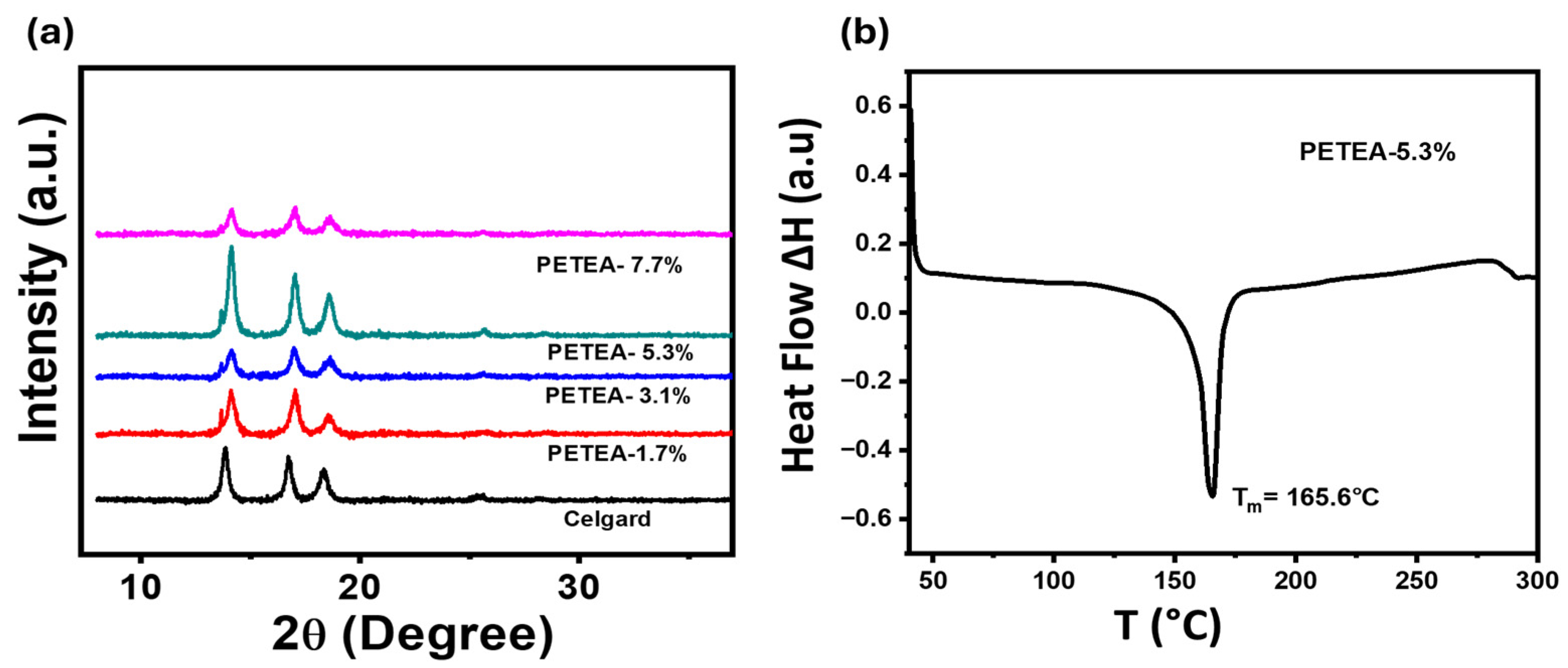
The diffraction pattern (Figure 2a) of Celgard exhibits distinct peaks indicative of crystalline structures. As the PETA content is changed, a new low-intensity peak at 13.3 °C emerges consistently, regardless of monomer content. This observation suggests that the QSE retains an amorphous or semicrystalline structure. The polymer network, formed during crosslinking, is predominantly amorphous, and the structural framework remains relatively consistent across different formulations. This amorphous nature is conducive to ion transport, as it allows greater mobility for ions in the quasi-solid-state system. From the endothermic peak (Figure 2b), the melting temperature is determined by identifying both the onset temperature (140 °C) and the peak temperature (165 °C). It can be concluded that the QSE material has a melting range between ~140–165 °C, indicating that it can remain solid at these temperatures.
The stability of the QSE during Li plating and stripping was evaluated with the use of Li||Li symmetric cells. The cells were cycled at room temperature (25 °C) with a constant current test at 0.1 mA/cm2 and a variable current test at 0.1, 0.2, 0.4, 0.6, and 1.0 mA/cm2. Figure 3a shows that plating/stripping of 0.1 mAh/cm2, the QSE has an overpotential of ~0.037 V, which remains almost the same until at least 450 h have passed. In Figure 3b, it is shown that as the current density increases from 0.1 to 0.2 to 0.4 mA/cm2, the QSE suffers large jumps in overpotential. However, at 0.4 mA/cm2, an SEI layer forms, which helps reduce the polarization of the QSE as its overpotential returns to its initial lower value. As the SEI layer forms, the QSE also becomes more resistant to polarization at even higher current densities of 0.6 and 1.0 mA/cm2, indicating the QSE could maintain very high cycling stability and suppress Li dendrite growth [30] over long periods of time at high current densities. The LSV curve of a stainless steel (SS) SS||QSE||Li cell in Figure 3d shows that the polymer electrolyte has a stable working potential window of up to 4.59 V, which is sufficient for Li-S battery applications and suggests that the QSE can also withstand higher voltage applications [31]. The lithium-ion transference number for the QSE was calculated through the application of the Evans-Vincent-Bruce method (Figure 3c) to obtain a value of tLi+ = 0.51 [32]. A typical lithium-ion transference number for nonaqueous solutions ranges from 0.20 to 0.40 and having a higher value is preferable because it indicates that less polarization occurs during battery cycling, resulting in lower overpotential [33,34]. This QSE exhibits an improved lithium-ion transference number as compared to typical electrolytes, which should boost the rate capabilities of the full Li-S battery system [17]. Figure 3e depicts the Nyquist plot of optimized QSE, exhibiting a conductivity of 3.41 × 10⁻⁵ S/cm, which is similar to some other QSEs on the order of 10−4 S/cm [16,35].
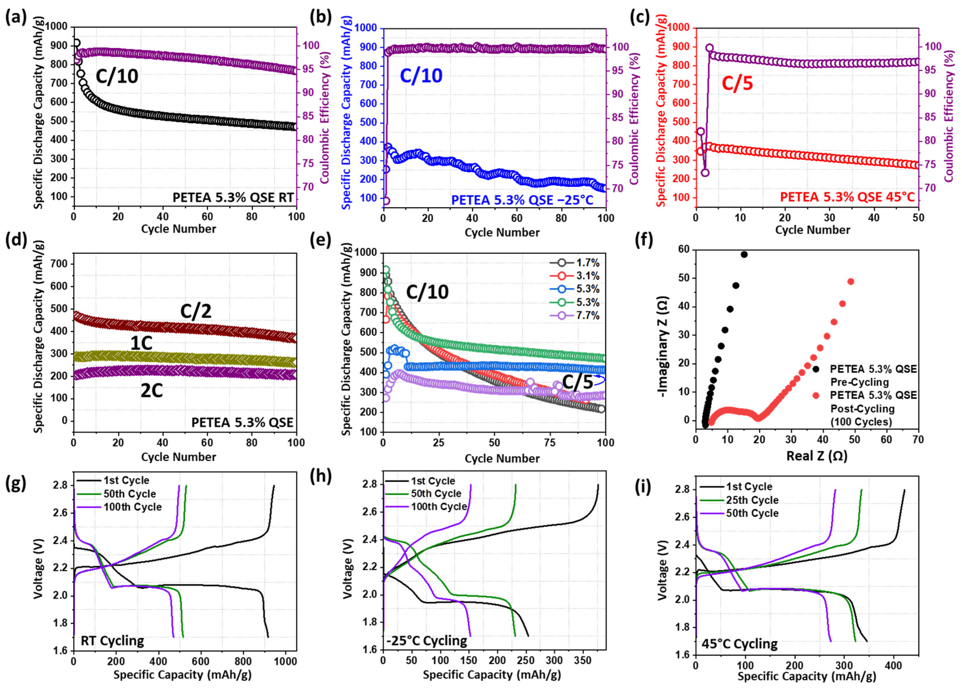
The temperature capabilities of the Li||QSE||S cells were tested at −25 °C, 25 °C, and 45 °C at C/10, C/10, and C/5 current rates, respectively (Figure 4a–c). C/10 cycling of the QSE at RT shows an initial decrease in capacity for ~10 cycles of SEI formation. The capacity is initially ~919 mAh/g with a capacity retention of 472 mAh/g (~52%) after 100 cycles, although it seems to have a stable capacity of 628 mAh/g after a few formation cycles, which is similar to other state-of-the-art QSEs with 63% and 54% retention after the same number of cycles [17,36]. At low temperatures (LT, −25 °C), the capacity is initially ~375 mAh/g with capacity retention of 41% after 100 cycles. At high temperatures (HT, 45 °C), the capacity is initially ~375 mAh/g with a capacity of 73% after 50 cycles with high-coulombic efficiency of >99% and 97%, respectively. A rate capability test of the QSE system was conducted at C/2, 1C, and 2C with the results shown in Figure 4d. Remarkably, faster charging rates seem to improve cycling stability. At C/2, the cell shows an initial specific discharge capacity of ~470 mAh/g with retention of 79% after 100 cycles as compared to other QSEs with a retention of 65% [37]. At a cycle rate of 1C, the cell has a discharge capacity of ~290 mAh/g and is stable for at least 100 cycles with a capacity retention of 91%. At a cycle rate of 2C, the cell has a discharge capacity of ~215 mAh/g and is stable with a capacity retention of 95%. As such, the QSE has robust performance throughout a range of current densities and is even more stable at faster charging rates. The composition of the QSE precursor solution was optimized for the system by testing PETEA concentrations of 1.7, 3.1, 5.3% and 7.7% in the precursor solution and monitoring discharge capacity in a cell configuration of Li||QSE||S. Figure 4e shows that 5.3% PETEA had a significantly higher discharge capacity than the other concentrations, so this formulation was used in all testing. Electrochemical impedance spectroscopy (EIS) was conducted before and after 100th cycles on the RT cell to evaluate changes in interfacial resistance (Figure 4f). The QSE resistance before cycling was 2.97 Ω and after cycling was 4.86 Ω. This only slight increase in impedance indicates that the electrode/electrolyte interface of the cell was highly stable throughout cycling. Additionally, cycling seems to have activated the charge transfer resistance, as there is no value before cycling, but the resistance is 14.75 Ω after long cycling. This is lower than comparable Li-S systems [17,38]. This suggests that the interface made between this QSE and the electrodes is very effective following the creation of a stable SEI layer [17]. The charge-discharge curve exhibits stable polarization voltages across a wide temperature range of −25 °C to 45 °C (Figure 4g–i).
Cyclic voltammetry (CV) was employed to assess the electrochemical performance of a Li-S battery, conducted at temperatures of 25 °C, −25 °C, and 45 °C as depicted in Figure 5. At 45 °C, the discharge peaks were observed at 1.91 V and 2.23 V, which correlated with the charge peaks at 2.71 V. In contrast, the discharge peaks demonstrated a shift from 2.57 V and exhibited a downward trend in voltage for the discharge peaks at 1.96 V and 2.25 V, as evidenced by the room temperature cyclic voltammetry (CV) analysis. The shift in the peaks at 45 °C is due to the enhanced kinetics, which facilitate sulfur reduction reactions (S8 to Li2S) more effectively. This indicates that the reduction peaks (discharge peaks) may occur at a slightly lower voltage. Additionally, elevated temperatures can enhance the solubility of polysulfides. In contrast, when the temperature is lowered to −25 °C, the kinetics and ion mobility of the reaction markedly decline, potentially influencing the electrochemical processes within the battery. A slower diffusion of lithium ions and polysulfides may result in higher overpotentials, as a greater energy requirement is necessary to drive redox reactions. This can potentially result in elevated potentials for both reduction and oxidation reactions (observed at 2.05 V and 2.32 V, corresponding to charge peaks at 2.89 V).
The evolution of the cathode’s during cycling was examined by performing SEM on the sulfur cathode in a pristine condition (Figure 6a), after QSE formation (Figure 6b), and after 100 cycles (Figure 6c). The initial pristine sulfur cathode is observed to have much non-uniformity on the surface. Following the formation of the QSE and then removal, some smooth remnants of the gel electrolyte are visible on the cathode. The QSE electrolyte and the cathode are visibly two separate materials, with the cathode being highly textured and layered and the gel electrolyte being smooth and conforming to the surface of the cathode. Following the 100th cycle, these two materials are much more interconnected. The cathode material is seen to be penetrating through the smooth gel and embedding into the electrolyte. This suggests that the QSE can physically retain polysulfides near the cathode. This retention may be attributed to the molecular structure of the electrolyte, which can trap polysulfides or impede their free movement due to the dense mesh or network of the electrolyte matrix [39]. By slowing the movement of polysulfides, rigid electrolytes help maintain the integrity and composition of the cathode material across multiple charge and discharge cycles at higher and lower temperatures. Raman spectroscopy was utilized to investigate the Li-S mechanism related to the ‘solid-liquid-solid’ phase during the charge/discharge process. Different LiPSs were identified by their respective vibrational frequencies. Figure 6d clearly illustrates the reduction of elemental sulfur (S8) and the dynamic evolution of various lithium LiPSs and lithium disulfide (Li2S2) during the discharging phase, as evidenced by disassembled electrodes after Raman spectroscopy. At an OCV of approximately 3.0V, the Raman spectrum displays characteristic peaks of S8 at around 150, 220, and 470 cm−1 [40]. Upon charging the cell to 2.8 V, notable changes occur in the Raman spectra, revealing the emergence of three distinct peaks indicative of the presence of mixed LiPS species. The peak at 380 cm−1 is a blend of S62−, S72−, and S82− species, while the peak at 470 cm−1 is associated with a mixture of S32−, S42−, S52−, and elemental sulfur (S4) [41]. Upon discharging to 2.2 V, the peak intensity decreases, and a pronounced peak at 515 cm−1 appears, signifying the formation of Li2S2. When subjected to a reduced voltage of 1.5 V, no prominent peaks were observed in the Raman spectrum. This suggests a gradual transformation toward the formation of Li2S2 to Li2S. Li2S displays minimal Raman activity because of its elementary ionic character and cubic crystalline structure, which gives rise to weak vibratory interactions with light. It is only the vibrational modes that alter the polarizability of a molecule that are Raman-active. Some of the modes present in Li2S do not meet this criterion, which results in their being undetectable. Furthermore, lithium disulfide (Li2S) can occur in either crystalline or amorphous phases. X-ray diffraction (XRD) is more sensitive to crystalline structures, whereas amorphous Li2S may not produce well-defined Raman signals. Ex-situ Raman spectroscopy is susceptible to complications due to exposure to air or sample handling, which can alter the material and make detection challenging. However, XRD patterns, especially for fully discharged cathodes, can be used to confirm the presence of Li2S [42]. The absence of any significant increase in peak intensity underscores the ongoing generation of Li2S2. This sequence of transformations is crucial for enhancing the electrochemical performance of lithium-sulfur batteries. The reversible interaction between sulfur and lithium sulfide (Li2S) effectively prevents the polysulfide shuttle effect. Strategic management and optimization of the formation and dissolution of Li2S2 reduces the loss of active materials, ensures stable performance over time, and maximizes the potential of sulfur’s high theoretical capacity. To investigate the parameters affecting the capacity fade of Li-S batteries, we utilized SEM was utilized to examine the microstructures of the sulfur cathodes after the first charge and discharge cycle. Between the charge and discharge states, distinct differences were observed. After a full discharge cycle, the cathode exhibited a thick Li2S2/Li2S film with cracks (Figure 6e). The films used caused structural degradation and were non-conductive and insoluble [43]. The SEM results indicate that the capacity degradation of the Li-S batteries was due to the formation of non-conductive Li2S2/Li2S films and the formation of large sulfur agglomerates on the sulfur cathodes (Figure 6f). It is worth noting that no sulfur accumulation was observed on the cathode samples after the completion of the first full state of charge.
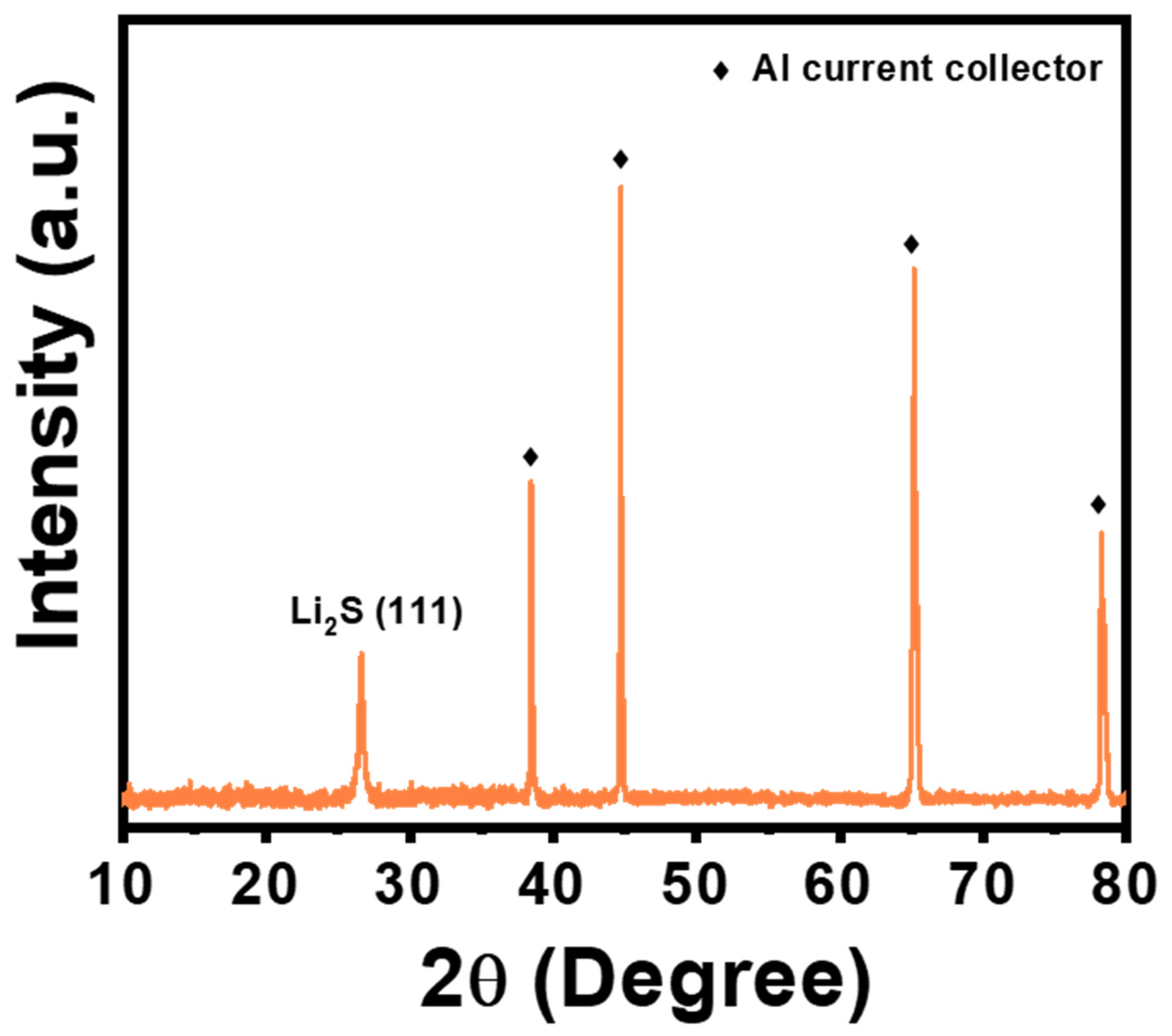
The quasi-solid electrolyte offers the advantage of trapping polysulfides and enhancing electrochemical contact within the cell. To further investigate, cycled cathodes were subjected to XRD analysis as shown in Figure 7. XRD of the fully discharged sulfur electrode revealed a peak at approximately 26.6°, indicative of the formation of the Li2S phase. This suggests that sulfur is completely converted to Li2S during the cycling process.
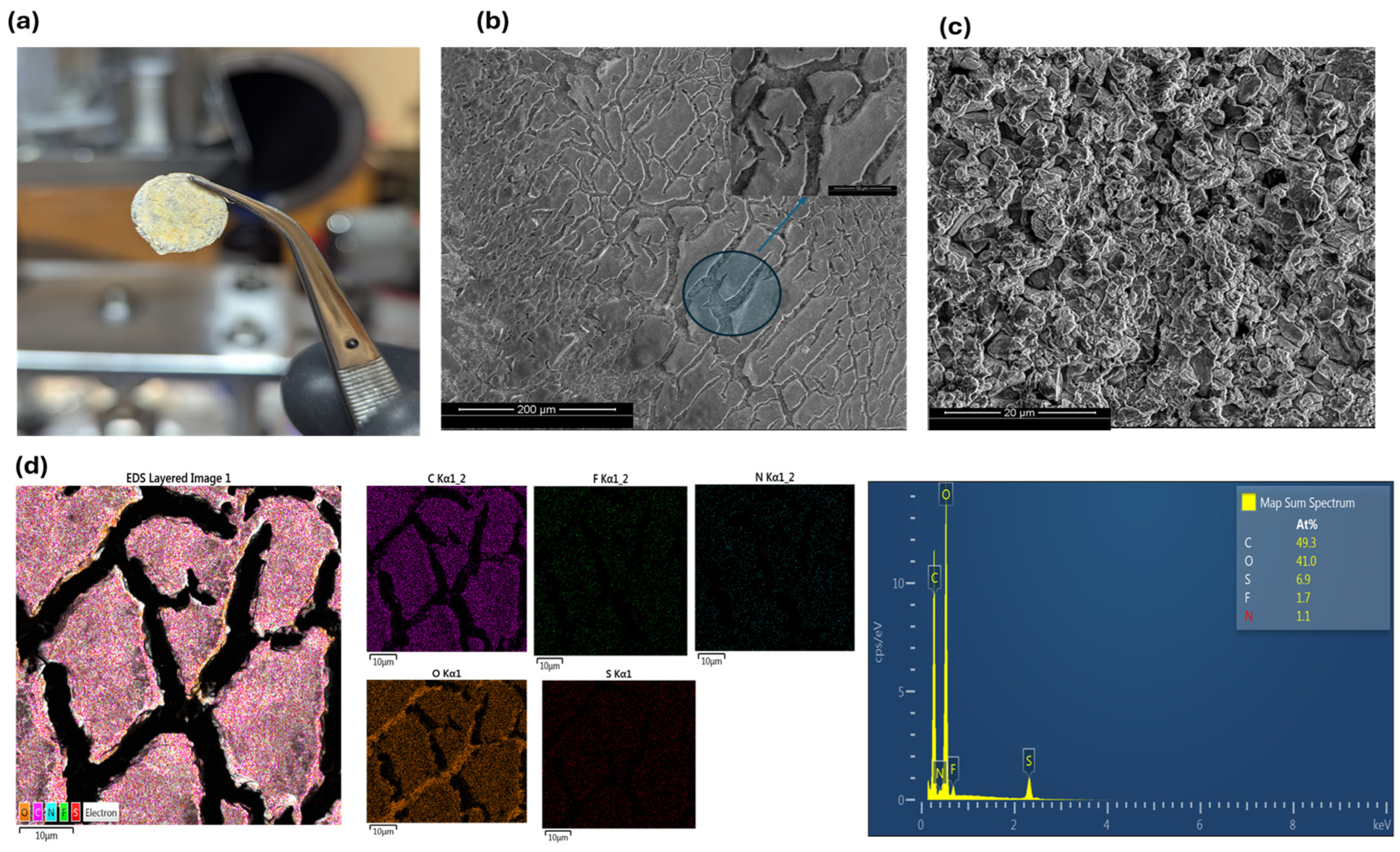
The optical image as in Figure 8a demonstrates that there is no significant formation of dendritic structures or excessive surface roughness, indicating that the lithium metal remains relatively smooth after cycling. The SEM image (Figure 8b,c) confirms no significant deposition of polysulfides on the lithium surface nor any visible signs of dendritic growth. The absence of such features lends further support to the claim that the QSE effectively prevents the polysulfide shuttle, thus ensuring a stable and uniform lithium deposition during cycling. The yellow-colored areas visible in the optical images are primarily electrolyte residue, as evidenced by the EDX analysis (Figure 8d). The spectrum shows dominant peaks of carbon (C) and oxygen (O), which are consistent with the organic components of the electrolyte. Additionally, a small amount of sulfur (S) is detected, indicating the presence of polysulfides formed during the cycling process. This confirms that the yellow areas are mainly electrolyte scraps with minor polysulfide deposition.

4. Conclusions

In summary, the present study on PETEA-based quasi-solid electrolytes (QSE), a robust composite film within a Celgard separator, has yielded several promising findings that could inform the development of advanced lithium-sulfur (Li-S) batteries. The structure was confirmed by scanning electron microscopy (SEM) imaging and demonstrated excellent electrochemical performance, including a stable overpotential (~0.035 V) after solid electrolyte interphase (SEI) layer formation and a stable working potential window up to 4.59 V. Additionally, the quasi-solid electrolyte (QSE) exhibited a high lithium-ion transference number of 0.51 and conductivity of 3.41 × 10⁻⁵ S/cm, indicating reduced polarization and enhanced rate capabilities. The QSE exhibited remarkable stability across a broad temperature spectrum, retaining a considerable capacity even at temperatures as low as −25 °C and as high as 45 °C. The implementation of accelerated charging rates resulted in a notable enhancement in the cycling stability of the system, accompanied by a considerable capacity retention at C/2, 1C, and 2C. The optimal concentration of PETEA was determined to be 5.3%. Electrochemical impedance spectroscopy (EIS) measurements revealed the presence of stable electrode/electrolyte interfaces with low charge transfer resistance following the cycling process. Morphological analysis via scanning electron microscopy (SEM) and Raman spectroscopy confirmed effective polysulfide retention and management of the polysulfide shuttle effect, which is crucial for improving battery performance. Further optimization of scalable synthesis and fabrication processes will facilitate commercial application, particularly in contexts where extreme temperatures and high current densities are a concern. The PETEA-based QSE provides a robust basis for the development of next-generation lithium-sulfur batteries with enhanced performance, safety, and durability.

Author Contributions

Conceptualization, S.D. and V.P.; methodology, K.N.G. and S.D.; software, K.N.G. and S.D.; validation, K.N.G., S.D. and V.P.; formal analysis, K.N.G. and S.D.; investigation, K.N.G. and S.D. and V.P.; resources, V.P.; data curation, K.N.G., S.D. and A.C.; writing—original draft preparation, K.N.G. and S.D.; writing—review and editing, A.C. and V.P.; visualization, S.D. and V.P.; supervision, V.P.; project administration, V.P.; funding acquisition, V.P. All authors have read and agreed to the published version of the manuscript.

Funding

This research received no external funding.

Data Availability Statement

Data is available from the authors upon request.

Conflicts of Interest

The authors declare no conflicts of interest.

References

  1. Patel, J.; Patel, R.; Saxena, R.; Nair, A. Thermal analysis of high specific energy NCM-21700 Li-ion battery cell under hybrid battery thermal management system for EV applications. J. Energy Storage 2024, 88, 111567. [Google Scholar] [CrossRef]
  2. Rahmani, E.; Fattahi, A.; Panahi, E.; Mahmoudi, Y. Thermal management improvement for a pack of cylindrical batteries using nanofluids and topological modifications. J. Power Sources 2023, 564, 232876. [Google Scholar] [CrossRef]
  3. Fang, X.; Peng, H. A Revolution in Electrodes: Recent Progress in Rechargeable Lithium–Sulfur Batteries. Small 2015, 11, 1488–1511. [Google Scholar] [CrossRef]
  4. Cutting cobalt. Nat. Energy 2020, 5, 825. [CrossRef]
  5. Schmuch, R.; Wagner, R.; Hörpel, G.; Placke, T.; Winter, M. Performance and cost of materials for lithium-based rechargeable automotive batteries. Nat. Energy 2018, 3, 267–278. [Google Scholar] [CrossRef]
  6. Sun, J.; Wang, T.; Gao, Y.; Pan, Z.; Hu, R.; Wang, J. Will lithium-sulfur batteries be the next beyond-lithium ion batteries and even much better? InfoMat 2022, 4, 12359. [Google Scholar] [CrossRef]
  7. Zhang, W.; Lu, J.; Guo, Z. Challenges and future perspectives on sodium and potassium ion batteries for grid-scale energy storage. Mater. Today Proc. 2021, 50, 400–417. [Google Scholar] [CrossRef]
  8. Manthiram, A.; Fu, Y.; Chung, S.-H.; Zu, C.; Su, Y.-S. Rechargeable Lithium–Sulfur Batteries. Chem. Rev. 2014, 114, 11751–11787. [Google Scholar] [CrossRef]
  9. Yin, Y.; Xin, S.; Guo, Y.; Wan, L. Lithium–Sulfur Batteries: Electrochemistry, Materials, and Prospects. Angew. Chem. Int. Ed. 2013, 52, 13186–13200. [Google Scholar] [CrossRef]
  10. Benveniste, G.; Sánchez, A.; Rallo, H.; Corchero, C.; Amante, B. Comparative life cycle assessment of Li-Sulphur and Li-ion batteries for electric vehicles. Resour. Conserv. Recycl. Adv. 2022, 15, 200086. [Google Scholar] [CrossRef]
  11. Mikhaylik, Y.V.; Akridge, J.R. Polysulfide Shuttle Study in the Li/S Battery System. J. Electrochem. Soc. 2004, 151, A1969–A1976. [Google Scholar] [CrossRef]
  12. Luo, Y.; Wang, L.; Wei, Z.; Huang, Q.; Deng, Y.; Zheng, Z. Cracking-Controlled Slurry Coating of Mosaic Electrode for Flexible and High-Performance Lithium–Sulfur Battery. Adv. Energy Mater. 2023, 13, 2203621. [Google Scholar] [CrossRef]
  13. Sun, K.; Wu, Q.; Tong, X.; Gan, H. Electrolyte with Low Polysulfide Solubility for Li–S Batteries. ACS Appl. Energy Mater. 2018, 1, 2608–2618. [Google Scholar] [CrossRef]
  14. Bhargav, A.; He, J.; Gupta, A.; Manthiram, A. Lithium-Sulfur Batteries: Attaining the Critical Metrics. Joule 2020, 4, 285–291. [Google Scholar] [CrossRef]
  15. Wang, Y.; Zhong, W. Development of Electrolytes towards Achieving Safe and High-Performance Energy-Storage Devices: A Review. ChemElectroChem 2015, 2, 22–36. [Google Scholar] [CrossRef]
  16. Judez, X.; Martinez-Ibañez, M.; Santiago, A.; Armand, M.; Zhang, H.; Li, C. Quasi-solid-state electrolytes for lithium sulfur batteries: Advances and perspectives. J. Power Sources 2019, 438, 226985. [Google Scholar] [CrossRef]
  17. Liu, M.; Zhou, D.; He, Y.-B.; Fu, Y.; Qin, X.; Miao, C.; Du, H.; Li, B.; Yang, Q.-H.; Lin, Z.; et al. Novel gel polymer electrolyte for high-performance lithium–sulfur batteries. Nano Energy 2016, 22, 278–289. [Google Scholar] [CrossRef]
  18. Bhardwaj, R.K.; Zitoun, D. Recent Progress in Solid Electrolytes for All-Solid-State Metal(Li/Na)–Sulfur Batteries. Batteries 2023, 9, 110. [Google Scholar] [CrossRef]
  19. Han, D.-D.; Liu, S.; Liu, Y.-T.; Zhang, Z.; Li, G.-R.; Gao, X.-P. Lithiophilic gel polymer electrolyte to stabilize the lithium anode for a quasi-solid-state lithium–sulfur battery. J. Mater. Chem. A 2018, 6, 18627–18634. [Google Scholar] [CrossRef]
  20. Ren, Y.; Manthiram, A. A Dual-Phase Electrolyte for High-Energy Lithium–Sulfur Batteries. Adv. Energy Mater. 2022, 12, 2202566. [Google Scholar] [CrossRef]
  21. Qin, S.; Yu, Y.; Zhang, J.; Ren, Y.; Sun, C.; Zhang, S.; Zhang, L.; Hu, W.; Yang, H.; Yang, D. Separator-Free In Situ Dual-Curing Solid Polymer Electrolytes with Enhanced Interfacial Contact for Achieving Ultrastable Lithium-Metal Batteries. Adv. Energy Mater. 2023, 13, 2301470. [Google Scholar] [CrossRef]
  22. Koralalage, M.K.; Shreyas, V.; Arnold, W.R.; Akter, S.; Thapa, A.; Narayanan, B.; Wang, H.; Sumanasekera, G.U.; Jasinski, J.B. Functionalization of Cathode–Electrolyte Interface with Ionic Liquids for High-Performance Quasi-Solid-State Lithium–Sulfur Batteries: A Low-Sulfur Loading Study. Batteries 2024, 10, 155. [Google Scholar] [CrossRef]
  23. Gupta, A.; Bhargav, A.; Jones, J.-P.; Bugga, R.V.; Manthiram, A. Influence of Lithium Polysulfide Clustering on the Kinetics of Electrochemical Conversion in Lithium–Sulfur Batteries. Chem. Mater. 2020, 32, 2070–2077. [Google Scholar] [CrossRef]
  24. Gupta, A.; Manthiram, A. Unifying the clustering kinetics of lithium polysulfides with the nucleation behavior of Li2S in lithium–sulfur batteries. J. Mater. Chem. A 2021, 9, 13242–13251. [Google Scholar] [CrossRef]
  25. Kim, S.; Jung, J.; Kim, I.; Kwon, H.; Cho, H.; Kim, H.-T. Tuning of electrolyte solvation structure for low-temperature operation of lithium–sulfur batteries. Energy Storage Mater. 2023, 59, 102763. [Google Scholar] [CrossRef]
  26. Bai, Z.; Fan, K.; Guo, M.; Wang, M.; Yang, T.; Wang, N. Rational Design of a Cost-Effective Biomass Carbon Framework for High-Performance Lithium Sulfur Batteries. Batteries 2023, 9, 594. [Google Scholar] [CrossRef]
  27. Huang, L.; Lu, T.; Xu, G.; Zhang, X.; Jiang, Z.; Zhang, Z.; Wang, Y.; Han, P.; Cui, G.; Chen, L. Thermal runaway routes of large-format lithium-sulfur pouch cell batteries. Joule 2022, 6, 906–922. [Google Scholar] [CrossRef]
  28. Qu, W.; Xia, J.; Luo, C.; Zhang, C.; Chen, R.; Lv, W.; Yang, Q. Lithium-Sulfur Batteries at Extreme Temperatures: Challenges, Strategies and Prospects. Energy Environ. Mater. 2023, 6, 12444. [Google Scholar] [CrossRef]
  29. Shen, Z.; Shen, Z.; Zhong, J.; Zhong, J.; Jiang, S.; Jiang, S.; Xie, W.; Xie, W.; Zhan, S.; Zhan, S.; et al. Polyacrylonitrile Porous Membrane-Based Gel Polymer Electrolyte by In Situ Free-Radical Polymerization for Stable Li Metal Batteries. ACS Appl. Mater. Interfaces 2022, 14, 41022–41036. [Google Scholar] [CrossRef]
  30. Nguyen, A.; Verma, R.; Song, G.; Kim, J.; Park, C. In Situ Polymerization on a 3D Ceramic Framework of Composite Solid Electrolytes for Room-Temperature Solid-State Batteries. Adv. Sci. 2023, 10, e2207744. [Google Scholar] [CrossRef]
  31. Pal, P.; Ghosh, A. Robust Succinonitrile Plastic Crystal-Based Ionogel for All-Solid-State Li-Ion and Dual-Ion Batteries. ACS Appl. Energy Mater. 2020, 3, 4295–4304. [Google Scholar] [CrossRef]
  32. Evans, J.; Vincent, C.A.; Bruce, P.G. Electrochemical measurement of transference numbers in polymer electrolytes. Polymer 1987, 28, 2324–2328. [Google Scholar] [CrossRef]
  33. Xu, K. Nonaqueous Liquid Electrolytes for Lithium-Based Rechargeable Batteries. Chem. Rev. 2004, 104, 4303–4418. [Google Scholar] [CrossRef] [PubMed]
  34. Peng, H.; Zhang, Y.; Chen, Y.; Zhang, J.; Jiang, H.; Chen, X.; Zhang, Z.; Zeng, Y.; Sa, B.; Wei, Q.; et al. Reducing polarization of lithium-sulfur batteries via ZnS/reduced graphene oxide accelerated lithium polysulfide conversion. Mater. Today Energy 2020, 18, 100519. [Google Scholar] [CrossRef]
  35. Chang, Z.; Yang, H.; Zhu, X.; He, P.; Zhou, H. A stable quasi-solid electrolyte improves the safe operation of highly efficient lithium-metal pouch cells in harsh environments. Nat. Commun. 2022, 13, 1510. [Google Scholar] [CrossRef]
  36. Li, W.; Pang, Y.; Zhu, T.; Wang, Y.; Xia, Y. A gel polymer electrolyte based lithium-sulfur battery with low self-discharge. Solid State Ionics 2018, 318, 82–87. [Google Scholar] [CrossRef]
  37. Zhu, S.; Ma, F.; Wang, Y.; Yan, W.; Sun, D.; Jin, Y. New small molecule gel electrolyte with high ionic conductivity for Li–S batteries. J. Mater. Sci. 2017, 52, 4086–4095. [Google Scholar] [CrossRef]
  38. Jean-Fulcrand, A.; Jeon, E.J.; Karimpour, S.; Garnweitner, G. Cross-Linked Solid Polymer-Based Catholyte for Solid-State Lithium-Sulfur Batteries. Batteries 2023, 9, 341. [Google Scholar] [CrossRef]
  39. Hu, C.; Chen, H.; Shen, Y.; Lu, D.; Zhao, Y.; Lu, A.-H.; Wu, X.; Lu, W.; Chen, L. In situ wrapping of the cathode material in lithium-sulfur batteries. Nat. Commun. 2017, 8, 479. [Google Scholar] [CrossRef]
  40. Xue, L.; Li, Y.; Hu, A.; Zhou, M.; Chen, W.; Lei, T.; Yan, Y.; Huang, J.; Yang, C.; Wang, X.; et al. In Situ/Operando Raman Techniques in Lithium–Sulfur Batteries. Small Struct. 2022, 3, 2100170. [Google Scholar] [CrossRef]
  41. Hagen, M.; Schiffels, P.; Hammer, M.; Dörfler, S.; Tübke, J.; Hoffmann, M.J.; Althues, H.; Kaskel, S. In-Situ Raman Investigation of Polysulfide Formation in Li-S Cells. J. Electrochem. Soc. 2013, 160, A1205–A1214. [Google Scholar] [CrossRef]
  42. Yeon, J.-T.; Jang, J.-Y.; Han, J.-G.; Cho, J.; Lee, K.T.; Choi, N.-S. Raman Spectroscopic and X-ray Diffraction Studies of Sulfur Composite Electrodes during Discharge and Charge. J. Electrochem. Soc. 2012, 159, A1308–A1314. [Google Scholar] [CrossRef]
  43. Yan, J.; Liu, X.; Li, B. Capacity Fade Analysis of Sulfur Cathodes in Lithium–Sulfur Batteries. Adv. Sci. 2016, 3, 1600101. [Google Scholar] [CrossRef] [PubMed]
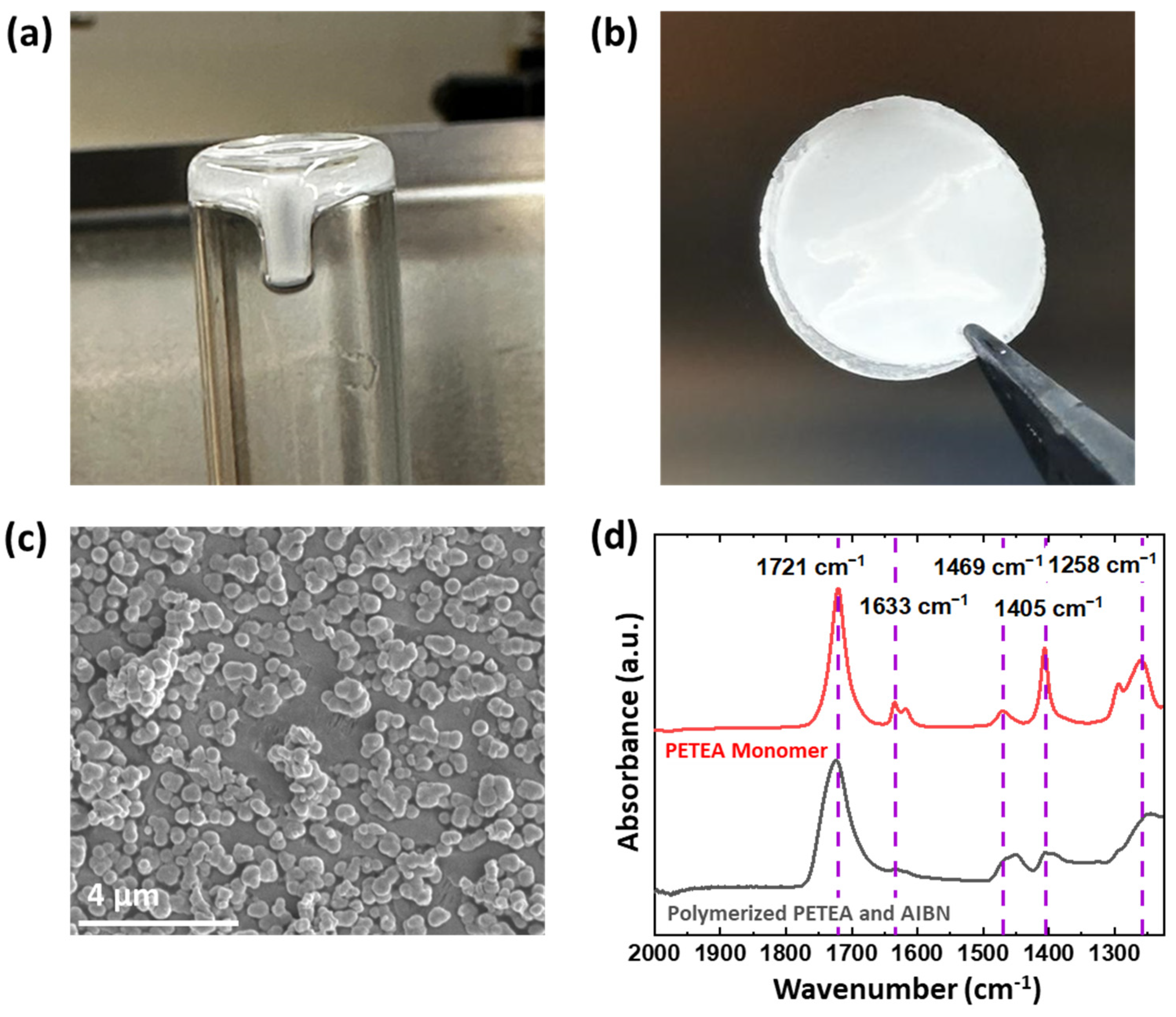
Figure 1. Images of polymerized precursor solution (optical image) (a) in vial (b) around separator. (c) SEM image of the separator with the QSE formed insitu. (d) FTIR spectra of PETEA monomer and polymerized QSE.
Batteries 10 00349 g001
Figure 2. (a) XRD of as developed QSE with different concentration of PETEA and (b) DSC of QSE (5.3% PETEA).
Batteries 10 00349 g002
Figure 3. Voltage profiles of Li||Li symmetrical cells at 25 °C (a) at constant current of 0.1 mA/cm2, (b) with varying current rates. (c) Nyquist plot for symmetric cell before and after polarization. (inset) the current-time response at RT with an applied voltage of 20 mV. (d) LSV curve of QSE electrolyte at 25 °C and (e) Nyquist plot of SS|QSE|SS cell at 25 °C.
Batteries 10 00349 g003
Figure 4. Long-term cycling performance of Li-S battery with QSE at (a) 25 °C (b) −25 °C (c) 45 °C. (d) Rate capability test of Li-S battery with QSE at 25 °C. (e) Cycling performance of Li-S batteries with various monomer concentrations within QSE at 25 °C. (f) Nyquist plot of Li||5.3%PETEA||S battery before cycling and after the 100th cycle. Charge-discharge curves of Li-S batteries with 5.3% PETEA QSE at (g) 25 °C (h) −25 °C (i) 45 °C.
Batteries 10 00349 g004
Figure 5. CV of Li||5.3%PETEA||S battery at (a) 25 °C (b) 45 °C (c) −25 °C.
Batteries 10 00349 g005
Figure 6. SEM images of the sulfur cathode (a) in a pristine condition (b) after opening the in situ formed Li||QSE||S cell (c) after 100 cycles at RT. (d) Raman spectra of sulfur cathodes from Li||QSE||S cells at various charge states. SEM images of sulfur cathodes at (e) discharge states of 1.5 V and (f) charge states of 2.8 V.
Batteries 10 00349 g006
Figure 7. XRD of S cathode after cycling at discharged state.
Batteries 10 00349 g007
Figure 8. (a) Optical image of Li metal after disassembling the Li||S cell after cycling; SEM image of Li metal; (b) lower magnification; (c) higher magnification; (d) energy dispersive X-ray (EDX) analysis of Li metal surface after cycling of Li|S cell.
Batteries 10 00349 g008
Disclaimer/Publisher’s Note: The statements, opinions and data contained in all publications are solely those of the individual author(s) and contributor(s) and not of MDPI and/or the editor(s). MDPI and/or the editor(s) disclaim responsibility for any injury to people or property resulting from any ideas, methods, instructions or products referred to in the content.