Abstract
High production rates and the constant expansion of production capacities for lithium-ion batteries will lead to large quantities of production waste in the future. The desired achievement of a circular economy presupposes that such rejects could be recovered. This paper presents a two-staged process route that allows one to recover graphite and conductive carbon black from already coated negative electrode foils in a water-based and function-preserving manner, and it makes it directly usable as a particle suspension for coating new negative electrodes. In a first step, coating residues, which accumulate in production (as offcuts or rejects for example), are decoated in an aqueous ultrasonic bath. The ultrasonic bath also serves as a pre-thickener. As a result, high mass concentrations of active material can already be achieved in the water after the first process step. Water is then removed from the negative electrode suspension in a subsequent step by applying dynamic cross-flow filtration. With this unit operation, it is possible to concentrate the slurry residue to a solid content similar to that of the new electrode slurries used for coatings. An important criterion for the direct utilization of production waste is that the particle properties are affected as little as possible so that the suspension can be used directly for coating new films. This work presents the individual recycling process steps and their influence on the particle and slurry properties. The aim is to assess whether the recyclate is suitable for a coating of new negative electrodes and thus also for manufacturing batteries from 100% recycled material.
1. Introduction
The recycling of production residues is playing an increasingly important role in the sustainable and cost-saving production of goods. The ramp-up of mass production of lithium-ion batteries (LIBs) will lead to a dramatic increase in manufacturing scraps over the next few years.
A large proportion of LIBs are required as energy storage devices or as batteries for electric cars. The European Commission assumes that the number of battery electric vehicles (BEVs) and plug-in electric vehicles (PHEVs) in the EU will double by 2030. Growth of up to 700% is even forecasted for energy storage systems in the EU [1]. A study by Agora Verkehrswende and the Fraunhofer Institute for Systems and Innovation Research (ISI) from 2021 also predicted the trend of the growing lithium-ion battery market. According to this, cell production capacities of around 850 GWh are expected to be created in the EU by 2030 [2]. While the majority of these batteries have had a delayed impact on the recycling market due to their life cycle, production rejects occur directly. Therefore, they have a straight impact on recycling capacities. Production scrap rates of at least 10% are to be expected in LIB production [2]. With a specific capacity of 300 Wh/kg [3,4], a production scrap rate of 300,000 metric tons can therefore be expected for 2030. A large proportion of the production residues are generated as part of the quality requirements for the coating, during both the coating process itself and during the drying of the batteries. The residues from start-up and shutdown processes, as well as stamping residues from cell production, also make up a large proportion of the production residues. The hydro- and pyrometallurgical recycling processes are already established on an industrial scale. They are primarily geared toward recovering the metallic components from end-of-life batteries, whereby the graphite as the active material of the negative electrode and the carbon black as the conductive additive are not recovered. For this purpose, the battery packs are sorted, discharged and partially dismantled as part of pre-treatment processes. In the case of pyrometallurgical recycling, a pre-treatment is optional, as the batteries are incinerated in a melting furnace at high temperature and the valuable metals are found in the slag and melt anyway. These can then be recovered in high purity using selective dissolution and precipitation processes as part of the hydrometallurgical recycling [5,6,7,8,9,10]. The processes mentioned recycle the battery waste on a material level and have disadvantages such as being harmful to the environment, requiring complex processing and purification steps and also the high consumption of chemicals and/or energy [10,11].
In contrast to the processes already described, direct recycling enables recovery at a particulate level. In this case, the materials are recovered holistically and in a function-preserving manner. Production residues in the form of slurry residues that remain in containers, coating residues and defective coatings before and after calendering are very suitable for direct mechanical recycling. In such cases, the materials of the negative and positive electrode are already separate from each other. This eliminates the need for complex separation processes to segregate the active materials, and it makes it possible to return them to the material stream of LIB production and to save resources. Large-scale mechanical recycling processes also include pre-treatment with the aim of enriching the black mass and removing as many metal components as possible from the films and housings [7,10,11,12]. Cutting and impact mills are often used here, after which the black mass can be separated from the metal residues using dry or wet sieving. A highly turbulent jet mill, for example, can be used to decoat the shredded foils. Manufacturers such as Hosokawa Alpine AG or Erdwich Zerkleinerungs-Systeme GmbH already offer a variety of devices for the mechanical decoating of lithium-ion batteries [13,14]. The collector foils emerge from these processes heavily shredded. This makes it difficult to cleanly separate the black mass from the film residue. Some of these processes also work at cryogenic temperatures to improve decoating. This is associated with high energy consumption. In the case of dry decoating in a jet mill, the black mass must be dispersed afterward in order to feed it into the production process of new LIBs. On a technical scale, various recycling processes are currently being researched with the aim of making the recycled particle systems directly usable for the manufacturing of new LIBs. Scott et al. [15] investigated the influence of second-life graphite on the cell performance of recycled half cells of a negative electrode. The graphite was obtained from electric car batteries by ultrasonic decoating of the negative electrodes. The removal of binders was then carried out by treatment with H2SO4 and pyrolysis. After the graphite was replaced with new binders, a new negative electrode was coated, calendered and assembled into a half cell and tested. They found that a cell made from recycled graphite only had 87% of the capacity of a reference cell made from pristine graphite. The reasons for this were assumed to be inhomogeneities caused by a reduction in the size of the graphite due to the high-intensity ultrasonic treatment. Binder residues and capsule effects of small graphite fragments were also suspected of impairing both the capacity and the cyclability. No detailed information was provided on the ultrasonic decoating process. Also, there was no investigation of the production residues.
Ren et al. [16] investigated the effect of mechanical decoating by stirring in combination with simultaneous exposure to ultrasound. The foils of negative electrodes from used LIBs from electric cars were used for this purpose. The combination of stirring and ultrasound enabled high decoating degrees with a high purity of the black mass being obtained, which was verified using XRF and SEM-EDS. The properties of the recycled slurry were not discussed in detail in the study. In comparison with this work, the investigations focused on end-of-life batteries instead of production scraps.
Lei et al. [17] showed an optimized method for ultrasonic decoating. For decoating, they used a sonotrode that applied ultrasound with very high intensity into a bath with a solvent and decoating agent. End-of-life batteries from an EV were used for these investigations. The aluminum and copper foils were clearly damaged by cavitation and pitting. This suggests that the recycled material must be significantly contaminated with these elements.
Ahuis et al. [18] presented a new process route that uses stirring for mechanical decoating. As part of a recycling process, negative electrodes are shredded. Subsequent stirring in water as a solvent and wet sieving enables the black mass to be recovered with a high recycling yield. From a mass concentration of 15 wt-%, however, recovery yields are significantly reduced due to limitations of the wet sieving process. Accordingly, recovery yields of more than 95% were only achieved up to 10 wt-%. The process, therefore, only allows a maximum of 10% recycled material to be fed back into the manufacturing process if high recovery yields are desired at the same time.
This work presents a simple and linear process route for the mechanical recycling of lithium-ion battery production residues. The process is specifically designed for the recovery of water-based coatings from negative electrodes. All coating residues that have not yet come into contact with electrolytes can be recycled before and after drying and calendering. In contrast to the aforementioned studies of Scott et al. [15], Ren et al. [16] and Lei et al. [17], the scope of the work is specifically on production residues. In comparison to Ahuis et al. [18], the materials should be recovered as a slurry with a high mass content so that they can also be returned to the production material stream in larger proportions. The two-staged process route consists of ultrasonic decoating in which the negative electrodes are decoated to the highest possible extent. The ultrasonic bath also serves as a pre-thickener in order to obtain a suspension with the highest possible mass concentration without impairing the decoating degree of the negative electrode. The obtained suspension is then fed to the process step of dynamic cross-flow filtration to remove water from the suspension until the mass content reaches a range of values comparable to the pastes of negative electrodes. This process route makes it possible to coat new negative electrodes from 100% recycled material without an additional process step. The influence of the individual recycling steps on the material and paste properties is to be investigated by subsequently checking the slurry properties and comparing them with a negative electrode paste produced in the laboratory. This procedure makes it possible to draw final conclusions about the quality of the recycling process.
2. Materials and Methods
The investigations were divided into two sections. Firstly, separate investigations were carried out on the ultrasonic decoating and dynamic cross-flow filtration process steps. This served to analyze the process behavior and to define optimal operating parameters to ensure that the process meets the requirements of recycling. In the second part, the knowledge gained was used to recycle the coating of negative electrodes on a technical scale. For this purpose, a total of 140 m of an electrode foil was decoated, after which the suspension was thickened to 43 wt-% using dynamic cross-flow filtration. The subsequent production of new coatings from 100% recycled material enables the process route to be characterized with regard to the material properties. Various analytical methods were therefore used before and after each recycling process.
The electrode paste used for the coating was produced in the laboratory using a dissolver. The water-based paste had a solid mass concentration of 43 wt-% and its composition is shown in Table 1.

Table 1.
The solid content of the electrode paste used for the investigations.
The graphite used was the spherical natural graphite MECHANO-CAP®1P1 (H.C. CARBON GmbH, Rednitzhembach, Germany). The graphite has a narrow particle size distribution and an average particle diameter of (20…24) µm, as determined by laser diffraction. C-NERGY SUPER C65 Conductive Carbon Black (Nanografi Nano Technology, Çankaya/Ankara, Turkey) was used as the conductive additive. The primary particles were spherical with a diameter of around 50 nm. The carbon black tended to agglomerate, so that it was present in the form of flake-like structures. The sodium-carboxymethylcellulose (CMC) was purchased from Sigma-Aldrich, Merck KGaA (Darmstadt, Germany). The CMC had an average molecular weight of 250,000 g/mol and a degree of substitution of 0.7. Additionally, styrene-butadiene rubber (SBR), with the commercial name PSBR100 from Targray Technology International Inc., (Kirkland, Canada) was used. The SBR was present in an aqueous solution with a solid mass content of 15 wt-%. The paste was prepared by dissolving the CMC in demineralized water by stirring with a dissolver. First the conductive carbon black and then the graphite were added and stirred until a homogeneous suspension was formed. Finally, the SBR was added at a low speed to prevent the shear labile particles from being destroyed.
The negative electrode films were coated with the PG-1818V automatic film applicator (Thierry GmbH, Stuttgart, Germany) using a height-adjustable squeegee with a coating width of 0.15 m. Afterward, the coated films were dried at room temperature (21 °C). The application speed was 10 mm/s. High-performance copper foil (Nanografi Nano Technology, Çankaya/Ankara, Turkey) with a thickness of 10 µm and a width of 0.2 m was used as the arrester foil. Prior to the gravimetric methods of the investigations presented here, the samples were stored in a drying oven at 50 °C for at least 2 h. Neither the electrode foils before recycling nor the foils coated with recycled material were calendered. This made it possible to assess the influence of recycling on the coating as directly as possible. Calendering would lead to a change in the coating, meaning that the effects may no longer be clearly attributable.
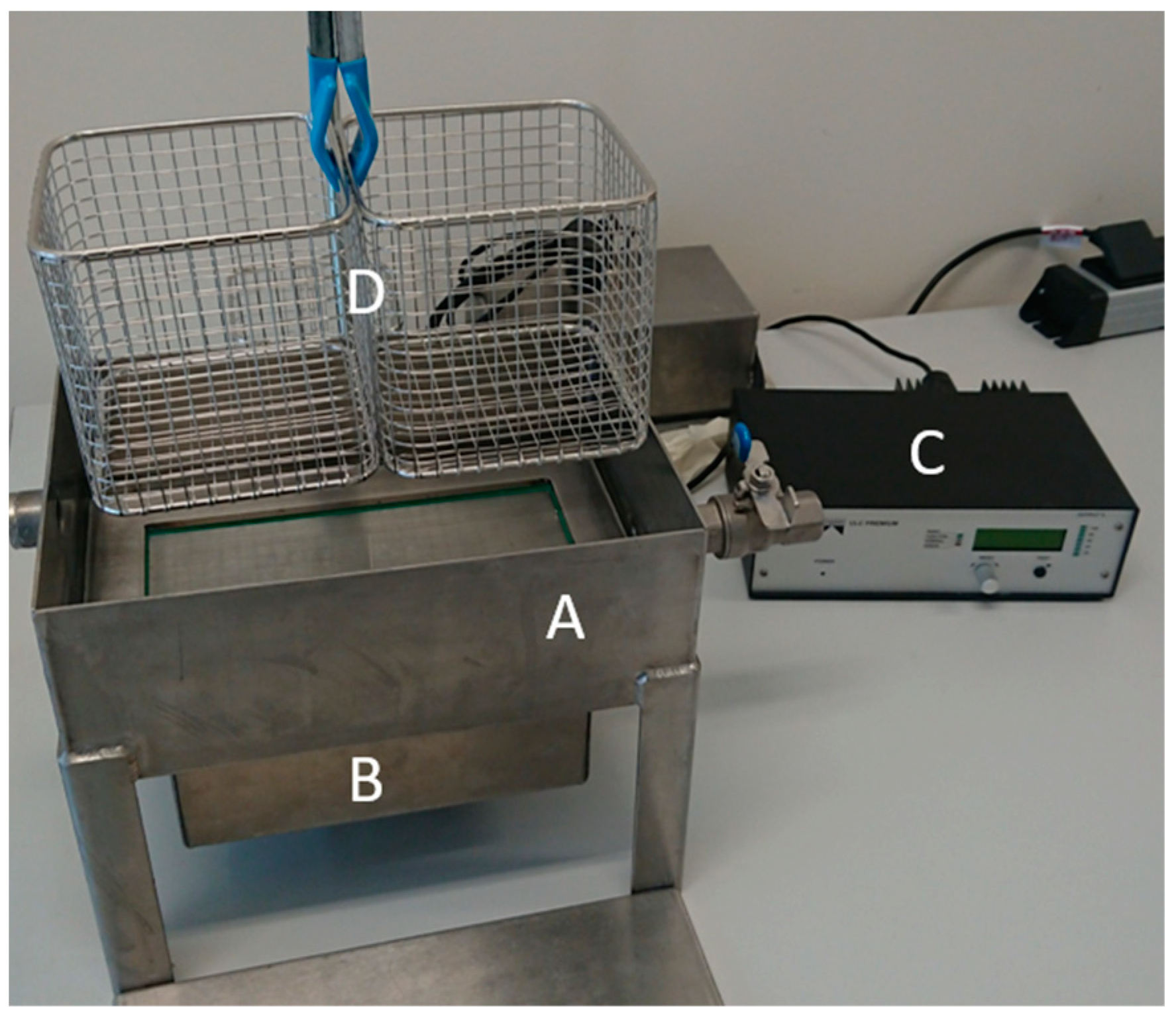
An ultrasonic bath measuring 0.28 m, 0.2 m and 0.1 m with an ultrasonic oscillator (Weber Ultrasonics AG, Karlsbad, Germany) at the bottom was manufactured for decoating the electrode foils. The ultrasonic oscillator was interchangeable so that frequencies of 29 kHz, 40 kHz and 120 kHz could be examined. The energy emitted into the ultrasonic bath was 200 W. The decoating was carried out with the sweep function activated, whereby the frequency generator slightly changed the oscillator frequency cyclically. This resulted in a homogeneous ultrasonic field and more uniform cleaning. In order to keep the samples at a constant distance from the oscillator to determine the degree of decoating, stainless-steel wire baskets were used. The base of the basket was positioned 0.01 m below the interface. Exposure times of 2 min, 5 min and 10 min were investigated. Large sheets of negative electrodes were decoated to increase the mass concentration of the ultrasonic bath after each series of tests. The resulting solid mass concentration was determined by drying a sample in the drying oven. As the thickening could only be carried out with limited accuracy, this method resulted in the mass concentrations mentioned in Section 3.1. The measurements carried out were triple tests. The setup is shown in Figure 1.
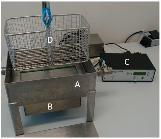
Figure 1.
Ultrasonic bath (A) with ultrasonic oscillator (B), frequency generator (C) and stainless-steel basket (D) to position the sample plates.
In order to prevent the decoating phenomenon caused by friction with the stainless-steel basket, the sample plates of the negative electrode were aligned with the coating facing upward. The sample plates were produced by punching out round samples with a diameter of 0.03 m from the center of the coated negative electrodes. By weighing the samples before and after decoating, as well as by determining the copper mass, the percentage degree of decoating ε could be calculated using Equation (1):
ε = (1 − (mpl, decoated − mcu)/(mpl, coated − mcu)) · 100.
Here, mpl, coated is the mass of the coated sample plate, mpl, decoated is the mass of the decoated sample after ultrasonic treatment and mcu is the mass of the punched copper foil. This was determined by weighing 45 punched, pure copper foils, resulting in a weight of (0.0625 ± 0.0001) g for one copper plate.
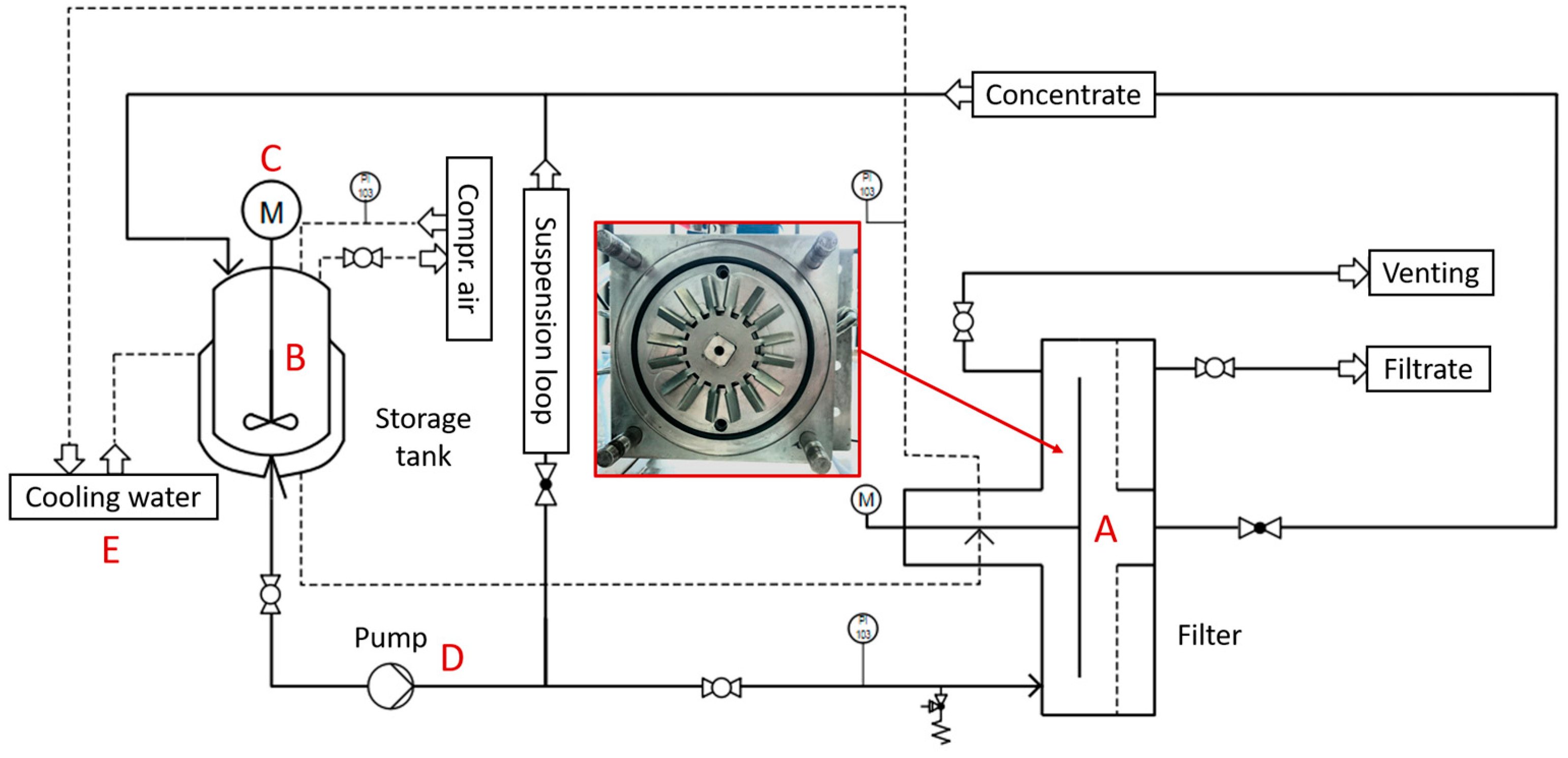
Following the investigations into the decoating of the negative electrodes, tests were carried out to thicken the suspension using dynamic cross-flow filtration. For this purpose, a small-scale test plant was set up, which consists of a dynamic cross-flow filter BoCross from the company BOKELA GmbH (Karlsruhe, Germany). Dynamic cross-flow filtration was used to concentrate the electrode suspension. A flow diagram of the test plant is shown in Figure 2.
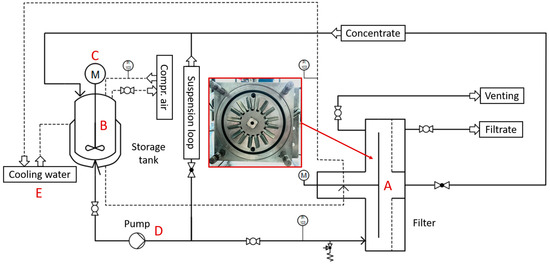
Figure 2.
Process flow chart of the plant for dynamic cross-flow filtration. With the filter (A), a stirred storage tank (B + C), a peristaltic pump (D) and a cooling water periphery (E) to cool the suspension, as well as the mechanical seal of the filter.
The filter had a rotor with a diameter of 0.13 m, which rotated in the filter chamber at a distance of 4 mm in front of the filter membrane. The filter membrane had a surface area of 0.013 m2. The filtration pressure was set using compressed air and a pressure reducer. The suspension was pumped through the filter chamber using a peristaltic pump. The storage tank held up to 9 L. The amount of filtrate produced was determined by weighing the collecting container. By knowing the solid mass concentration of the outgoing suspension, the solid mass concentration of the concentrate can be determined at any time during filtration using the amount of filtrate produced.
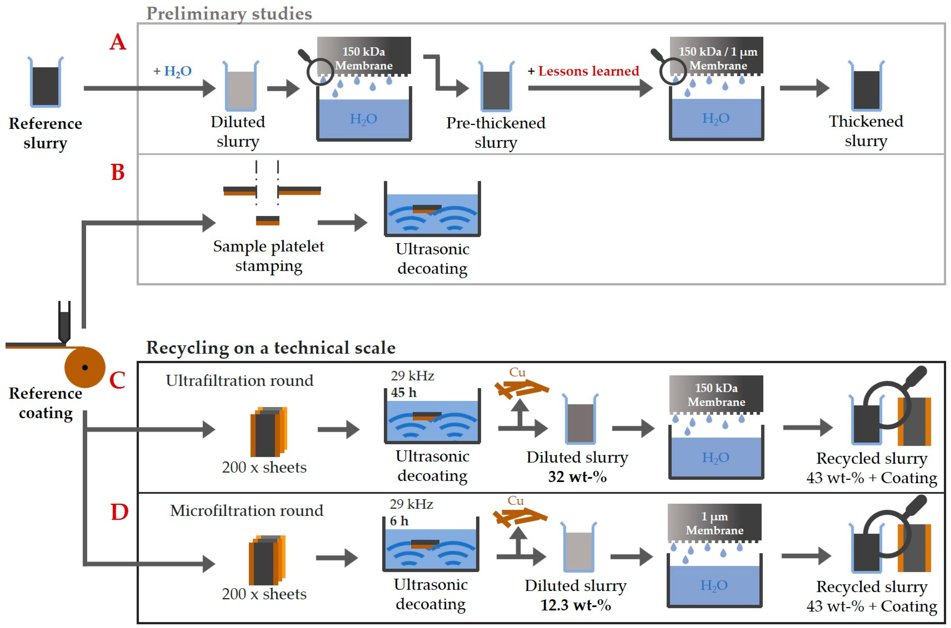
Figure 3 provides an overview of the experiments carried out as part of the work, including the various recycling processes. In the preliminary tests (A), the thickening was characterized on the basis of negative electrode suspensions with a mass concentration of 1 wt-%. The influence of filtration pressure and rotor speed was investigated. At a selected setting, a comparison was also made between a PES ultrafiltration membrane (MICRODYN-NADIR UP 150 P) with a molecular weight cut-off of 150 kDa and a microfiltration membrane (SABEU TRAKETCH PET/PP 1.0 R300) with a nominal pore size of 1 µm. In the additional preliminary studies (B), the behavior of the ultrasonic bath was investigated. For this purpose, sample plates were stamped out from the reference coating. These were then used to characterize the decoating in an ultrasonic bath by weighing the plates corresponding to Equation (1). An ICP-OES was used to quantize the copper impurities after the preliminary decoating tests with the ultrasonic bath. Finally, the findings from the preliminary tests were used to recycle on a technical scale (C,D). Therefore, the two steps of ultrasonic decoating and thickening by cross-flow filtration were combined. Two different recycling rounds were investigated. They differed in the duration of the total exposure time of the ultrasound to the particle system and in the choice of filter membrane (150 kDa or 1 µm) in the cross-flow filtration step.

Figure 3.
Schematic overview of the investigations carried out as part of this paper.
(C): In the run with the 150 kDa Ultrafiltration Membrane (UF), the decoating of the negative electrode sheets took place in an aqueous ultrasonic bath at a frequency of 29 kHz. In order to obtain enough of a suspension for thickening in the cross-flow filter, 200 sheets with a coating area of 0.15 m by 0.35 m each were decoated one after the other until the copper foils were seemingly cleaned. This resulted in a total exposure time of the ultrasound to the suspension of around 45 h. After the decoating, the ultrasonic bath had a solid mass concentration of 32 wt-%. At this point, no further decoating took place as the decoating does not work properly at higher solid mass concentrations. The suspension was then fed into the BoCross to filtrate with a UF up to a solid mass concentration of over 43 wt-%. Afterward, the solid mass concentration could be adjusted precisely to 43 wt-% by dilution with water. This made a comparison with the reference paste possible.
(D): In the recycling pass with the microfiltration membrane (MF), 200 sheets of negative electrode were also decoated in total. In this recycling round, the ultrasonic exposure time was reduced to 6 h to be more material friendly. In 6 h, only 33 sheets could be decoated in the ultrasonic bath. As a result, the suspension only had a mass concentration of 12.3 wt-% as less material was decoated in the same volume of water. In order to collect enough material for the subsequent step of the cross-flow filtration and to also decoat 200 sheets, this process was carried out for a total of 6 times. The electrode suspensions were collected each time and brought together for the subsequent filtration. The cross-flow filtration took place using a MF until a solid mass concentration of over 43 wt-%. Here too, the concentration was adjusted afterward to 43 wt-% by dilution with water.
In the case of the UF, 2.07 kg of suspension was thickened with an initial solid mass concentration of 31.7 wt-% up to a solid mass concentration of 46.7 wt-%. The filtration time was 15 min. In the case of using a MF membrane after the material-friendly ultrasonic decoating, 8.5 kg of electrode suspension with a mass content of 12.3 wt-% was concentrated to 44 wt-% during an overall filtration time period of 4.5 h. Selected analytical methods and equipment were used to examine the processed and recycled paste and the resulting coating. The particle size distribution was determined using the LUMiSizer (LUM GmbH, Berlin, Germany). For this purpose, a measurement method was used that was developed for the material system under investigation and is described in more detail by Yildiz et al. [19]. The rheology was characterized using a CS-10 rheometer (Bohlin Instruments GmbH, Pforzheim, Germany). The dynamic viscosity versus shear rate was measured using a plate–plate setup. In order to assess the coatings, SEM images were taken before and after recycling. In addition, 90° peel tests were carried out using the AMETEK LS1 (Lloyd Instruments Ltd., Bognor Regis, United Kingdom) to characterize the coating quality. The measurement methods are used for the results shown under Section 3.3.
3. Results
This section presents the experimental results for the decoating of copper foils by applying ultrasound. Of particular interest was achieving a high degree of decoating without damaging the copper foil through the occurring cavitation. Traditional ultrasonic cleaning baths contain dissolved impurities in very low concentrations or are filtered off directly. The ultrasonic bath investigated in the project was intended to act as a thickener. Afterward, this section presents the results for the dynamic cross-flow filtration. As already mentioned, an ultrafiltration membrane with a molecular weight cut-off of 150 kDa was used for the experimental studies. In addition, the filtration was also carried out using the MF at selected filter settings. Finally, the findings from the preliminary investigations were used to recycle the coated foils of the negative electrode on a technical scale and to re-coat the copper foils with the recovered paste. A comparison of the properties of the electrode materials before and after recycling enabled a qualitative assessment of the influence of the process route on the material properties.
3.1. Ultrasonic Delamination Characteristics of the Thick Negative Electrode Suspensions
To characterize the delamination of negative electrodes using ultrasound, decoating tests were carried out in an ultrasonic bath filled with water. In the course of the tests, the ultrasonic bath was thickened with large sheets of electrode foil to increase the mass concentration. After investigations of the decoating, the copper content of the ultrasonic bath was determined using an ICP-OES in combination with pulping the slurry to detect all the copper as ions. A copper content of 0.127 g, in terms of copper per kilogram solids, could be determined. This resulted in a 0.055 g copper per kilogram electrode slurry with a solid content of 43 wt-%. The role of copper impurities in the performance of the negative electrode films has not been broken down in the literature yet. The low copper content in the suspension after the preliminary decoating tests led to the decision to not further track the copper impurities in the recycling process.
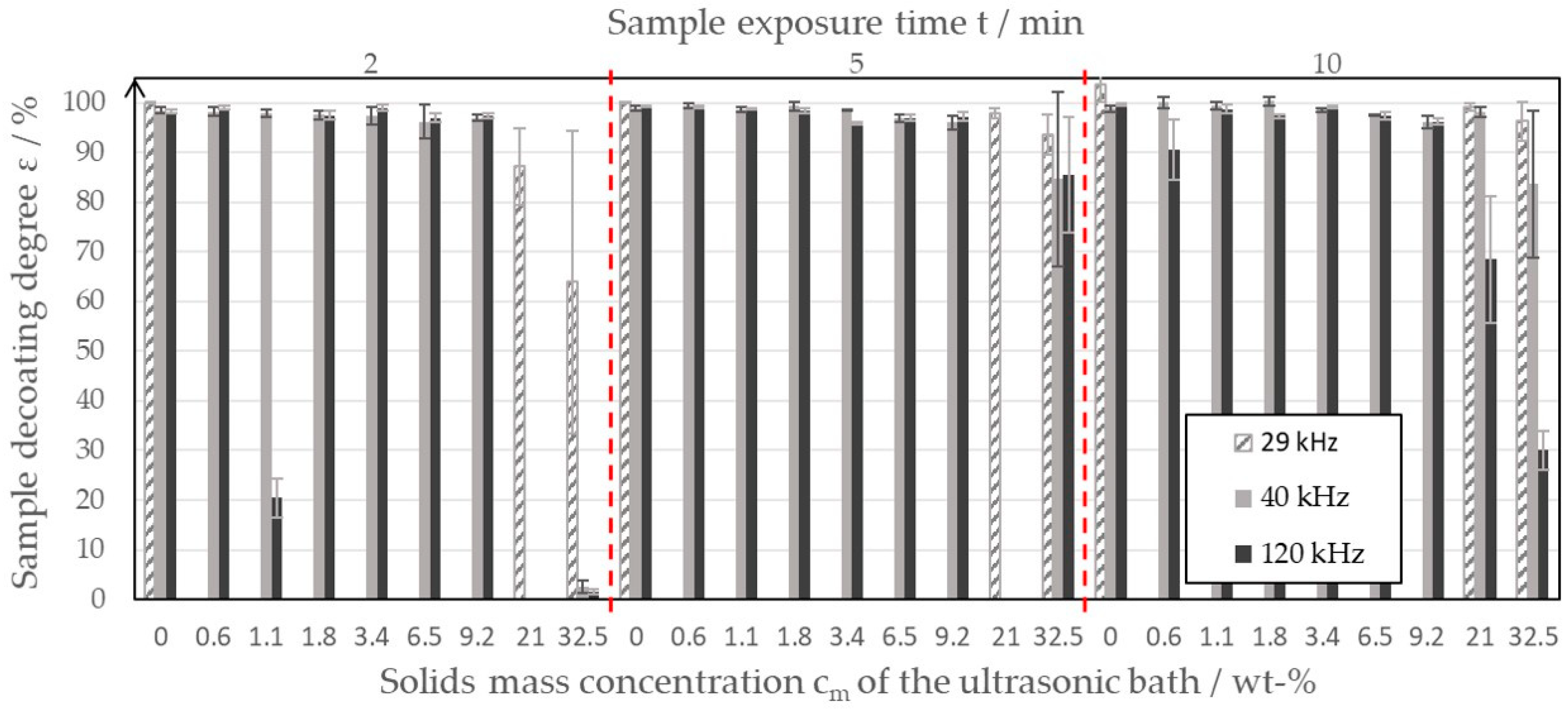
Figure 4 shows the results of the decoating studies as a combined bar chart.

Figure 4.
Decoating degree of the sample plates of the negative electrode at different ultrasonic bath mass concentrations and varying exposure times.
If one first compares the frequencies of 40 kHz and 120 kHz, it can be seen that, at solid mass concentrations between 0 wt-% and 9.2 wt-% (even with a decoating time of 2 min), a decoating degree of over 95% can be achieved. The degree of decoating decreases only slightly with increasing solid mass concentration. There are several reasons for the deviation of the decoating results for a frequency of 120 kHz and a solid mass concentration of 1.1 wt-%. It is possible that inhomogeneities in the ultrasonic field or small deviations in the handling of the sample plates led to the reduced measured values. Nevertheless, the trend toward high degrees of decoating at frequencies of 40 kHz and 120 kHz and low solid mass concentrations of up to 9.2 wt-% was clearly recognizable, whereby an exposure time of 2 min was found to be sufficient. Only at higher ultrasonic bath solid mass concentrations of up to 32.5 wt-% was an exposure time of 2 min found to be no longer sufficient to decoat the sample plates well. The high solid concentrations of the ultrasonic bath led to inhomogeneities in the ultrasonic field. Together with the increasing difficulties in handling the samples, this resulted in larger error bars at high mass concentrations. Due to measurement error, the measured values for 2 min and 5 min could not be evaluated and were therefore not included in Figure 4. At high mass concentrations, the measurement results were generally inconsistent, which is reflected in the large error bars. For example, the average degree of decoating achieved with an exposure time of 5 min was greater than with 10 min, which is contrary to the assumption that longer residence times lead to higher degrees of decoating. The effects of the inconsistent measured values and decreasing degrees of decoating were due to the fact that the increased mass concentration in the ultrasonic bath leads to a sediment of graphite on the ultrasonic oscillator. This hinders the transmission of the ultrasonic waves into the liquid phase and promotes inhomogeneities in the ultrasonic bath. Figure 4 shows that, at a frequency of 40 kHz, especially at high mass concentrations, higher degrees of decoating can always be achieved than at a frequency of 120 kHz. Thus, at a mass concentration of 32.5 wt-%, the sample sheets could only be decoated to an average of 30% at 120 kHz; whereas, at 40 kHz, an average decoating degree of 84% could still be achieved. For this reason, additional tests were carried out with a 29 kHz system at selected ultrasonic bath mass concentrations. The results are shown in Figure 4 as gray dashed bars. At 29 kHz, a further improvement in decoating performance could be seen. However, it should be noted that pitting of the copper foil can occur, especially at high exposure times and low solid mass concentrations. Based on the calculation of the decoating degree according to Equation (1), this resulted in ε values of >100%. Pitting must be prevented in a recycling process in order to minimize the contamination of the black mass with copper. Pitting is caused by aggressive cavitation on the surface of the copper foil or at the contact point of the sample plates and stainless-steel basket, and it is a known phenomenon of ultrasonic cleaning and fluid dynamics. Indications of pitting were no longer recognizable in the test series with mass concentrations of >0 wt-%. In contrast to the frequencies 40 kHz and 120 kHz, a decoating degree of 96% at a frequency of 29 kHz and an exposure time of 10 min can still be achieved on average when the ultrasonic bath is already thickened up to 32.5 wt-%. With an exposure time of 5 min, however, the average degree of decoating is still just over 93%. Based on the investigations, a comparatively low ultrasonic frequency of 29 kHz can therefore be recommended for decoating the water-based electrode foils. Such low frequencies are suitable for coarse soiling. The pressure fluctuations generate large cavitation bubbles, which, in turn, cause micro jets. These highly turbulent flow formations are expected to be the cause of the cleaning of the copper surface.
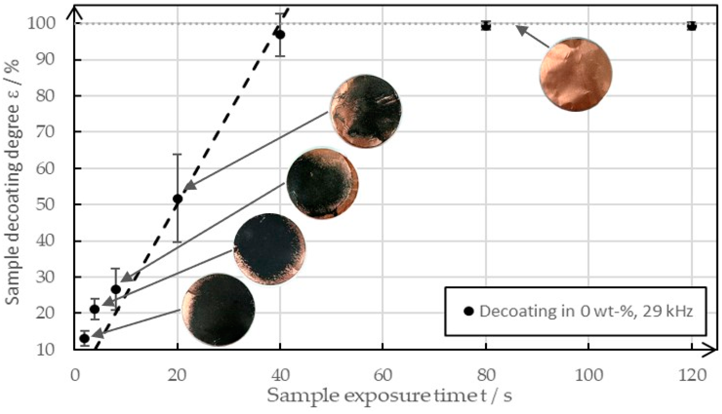
Figure 5 shows an example of the decoating behavior of various sample plates between 0 s and 120 s at a frequency of 29 kHz when in pure water in an ultrasonic bath.
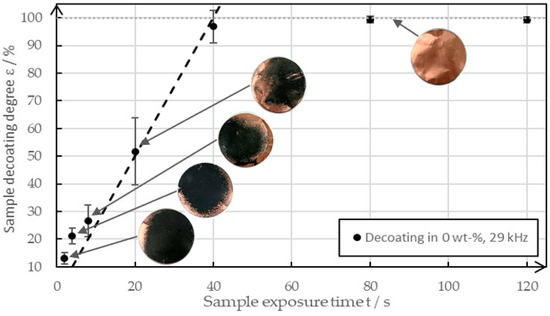
Figure 5.
The decoating behavior between 0 s and 120 s of ultrasonic exposure at a solid mass concentration of 0 wt-% and a frequency of 29 kHz.
It was easy to see that the degree of decoating increased almost linearly until it reached almost 100%. After that, it increased only minimally in the time interval and approached a degree of decoating of 100%. The images of the sample plates show that the decoating spread from the edge. The reason for this behavior was the raised surface, which provided cavitation nuclei. The image of the cleaned copper foil illustrates the high purity of the copper, which can leave the recycling process as a recyclable material after the decoating process. It can be assumed that a similar behavior is shown with increased solid concentrations, except that the gradient of the straight line was found to decrease, and thus decoating levels of >95% were achieved later. Due to the manual placement of the samples in the ultrasonic bath and inhomogeneities in the ultrasonic field, the degrees of decoating varied despite the same test parameters. When high degrees of decoating are achieved, small deviations appear as the time is sufficient for complete decoating anyway. The errors are distinct in the area of medium decoating degrees as small differences in the homogeneity of the coating and the ultrasonic field lead to high deviations in the degree of decoating.
3.2. Thickening with Dynamic Cross-Flow Filtration
After the decoating of the copper foils within the ultrasonic bath, the thickening of a negative electrode suspension with dynamic cross-flow filtration was tested. The filter characteristics were initially investigated using a 1 wt-% suspension, with thickening up to around 21 wt-%. The findings from these preliminary tests were then used to concentrate a suspension of electrode material to a solid mass concentration of 43 wt-%. The two investigated routes were micro- and ultrafiltration.
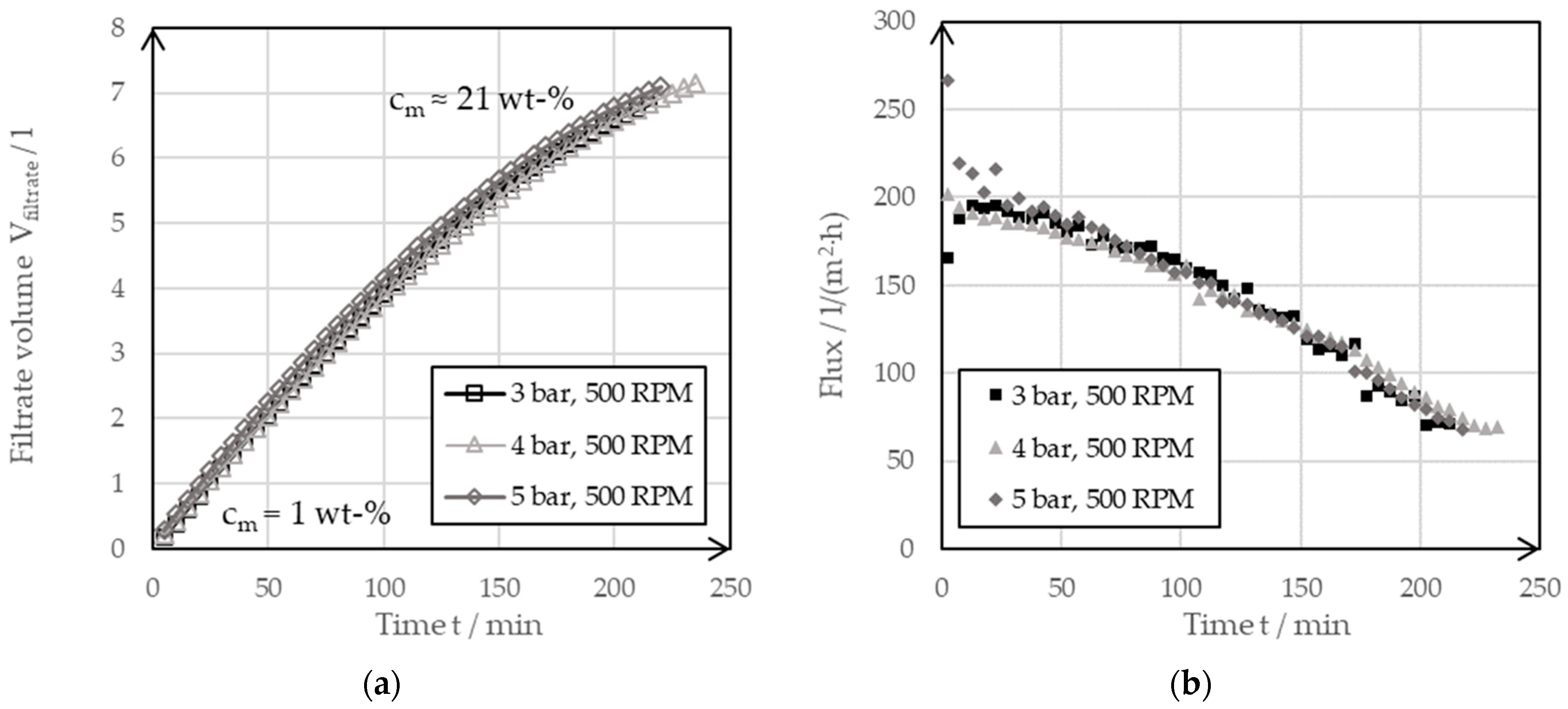
Figure 6 shows the filtrate flow (a) and flux curves (b) for the concentration of the investigated slurry with the BoCross filter system at different filter pressures and at a constant rotor speed using the UF.

Figure 6.
(a) Filter curve of a dynamic cross-flow filtration of a 1 wt-% suspension of the negative electrode at varying filter pressures of 3 bar, 4 bar and 5 bar but with the same rotation speeds of 500 RPM using the ultrafiltration membrane. (b) The derived filter fluxes of the filter curves.
From the almost congruent filter curves, it could be seen that the filtration pressure had no effect on the filter speed in the range considered. The filtration pressure had no influence on the filtrate flow curves. This could also be seen in the values for the transmembrane flux. If the suspension initially still had a solid mass concentration of 1 wt-%, the transmembrane flux had a value of 200 L per square meter of filter surface and hour (L/(m2·h)). Toward the end of filtration, this value dropped to 70 L/(m2·h). At this point, the suspension had a solid mass concentration of around 21 wt-%. The decreasing values resulted from an increasing resistance of the surface layer. The thickening process caused a growth of the surface layer on the UF membrane at the investigated rotational speed of n = 500 rpm. One way to speed up filtration is to increase the filtration pressure. However, the BoCross system used was limited to a maximum pressure of 5 bar. It was, therefore, advantageous to influence the flow resistance of the surface layer by adjusting the rotor speed. An increase in the speed resulted in an increase in the shear velocity, which reduced the height of the surface layer and thus the filter cake resistance.
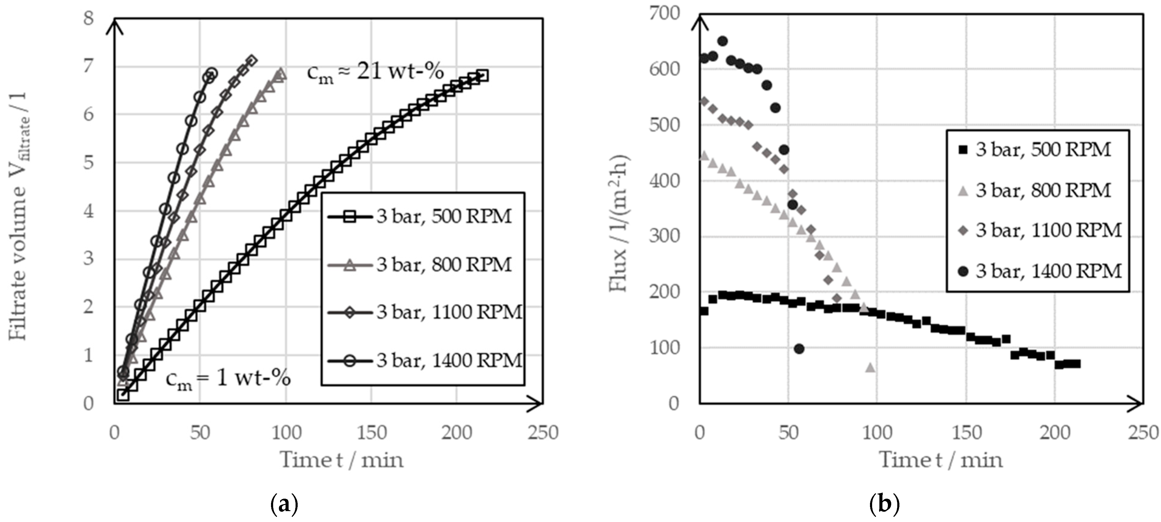
Figure 7 shows the transmembrane flux, which was dependent on time at a constant filtration pressure of 3 bar with a varying rotor speed in the range of 500 RPM up to 1400 RPM.

Figure 7.
(a) The filter curves of a dynamic cross-flow filtration of a 1 wt-% negative electrode suspension at varying rotor speeds of 500 RPM, 800 RPM, 1100 RPM and 1400 RPM but with constant filter pressures at 3 bar. (b) The derived filter fluxes of the filter curves.
The filtrate flow (a) became steeper at a higher rotor speed. The steepest curve resulted from a filtration, at the maximum adjustable speed of the system, of 1400 RPM. This was also clearly shown by the transmembrane flow curves (b), which were derived from the filtrate flow curves. While the initial flux at a rotor speed of 500 RPM was around 200 L/(m2·h), this could be increased to over 600 L/(m2·h) by increasing the rotor speed to 1400 RPM. This filter characteristic was due to the rotor-induced shear force over the filter membrane. Filtration caused a covering layer to build up on the membrane, which increased the filter resistance and reduced the flow. When the rotor speed was increased, this covering layer was continuously cut off, which meant that it no longer contributed to increasing the filter resistance. As filtration progressed, thickening occurred and the shear forces penetrated less and less deeply into the liquid phase, thus allowing a cover layer to build up and the transmembrane flux to decrease as the thickening progressed.
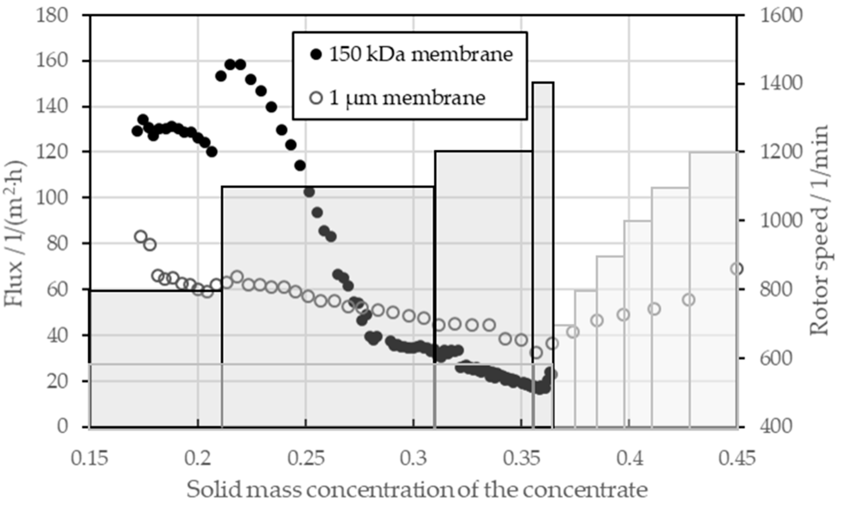
The findings were applied as lessons learned to the final thickening of an electrode suspension with 17 wt-%, which was obtained from the suspensions of the pressure and rotor speed tests. Thickening was tested for both a UF and a MF membrane. The transmembrane flux is presented in Figure 8 as a function of the solid mass concentration of the concentrate. The secondary axis shows the different set points for the rotor speed. The black circles and bars belong to the filtration with the UF membrane, and the gray circles and bars to the filtration with the MF membrane. A relative filtration pressure of 1 bar was selected for the tests, as the pressure, but this had no influence on the speed of the filtration process. For the UF, a total of 7.8 L of the 17 wt.-% suspension was added to the receiver tank so that the filtration took 9 h. For the MF, 3.2 l were filled in the receiver tank and the filtration took 3.5 h.

Figure 8.
Membrane flux for the dynamic crossflow filtration for a UF and MF membrane based on a pre-thickened suspension of a negative electrode and varying rotor speeds, which are visualized by the black and gray bars.
With the UF (black), the flux could be increased up to 160 L/(m2·h) under a solid mass concentration of 22 wt-% by increasing the rotor speed from 800 RPM to 1100 RPM. Between 22 wt-% and 28 wt-%, the flux dropped sharply to values below 40 L/(m2·h); even by increasing the speed up to 1400 RPM, the flux could not be increased further at high solid mass concentrations of the concentrate. Due to a leak in the cooling water system, only a solid mass concentration of 36.5 wt-% could be achieved in the UF as the leakage flow compensated for the filtrate flow from a certain point onward. At this point, the flux was 20 L/(m2·h). The rotor speed was increased step-by-step to minimize the shear forces on the particle system. The MF initially showed a lower flow between 60 L/(m2·h) and 80 L/(m2·h) despite the larger pore size. The MF was operated at an initial speed of 600 RPM to avoid filtrate turbidity by penetrating conductive carbon black particles. With a primary particle size of 50 nm, the carbon black particles had a smaller diameter than the pores of the MF membrane. The build-up of a covering layer at a speed of 600 RPM retained the carbon black particles at the start of filtration. During the thickening process, the flow rate of the MF decreased to 30 L/(m2·h) at a solid mass concentration of the concentrate of 36 wt-%. It should be noted here that the MF enabled higher fluxes than the UF from a solid mass concentration of 27.5 wt-%. From this point, the membrane resistance of the MF membrane was sufficiently low enough to allow the combined filter cake resistance and membrane to be lower at the MF than at the UF, despite lower rotor speeds. In the course of thickening, the rotor speed of the MF could also be increased without carbon black particles penetrating the membrane. This resulted in increasing flows from solid mass concentrations of 36 wt-%. Increasing the speed to 1200 RPM resulted in a flow of up to 70 L/(m2·h) at a solid mass concentration of the concentrate of 45 wt-%. Once enough water was removed to achieve a solid mass concentration of 43 wt-%, no further thickening took place.
3.3. Influence of the Recycling Process on the Material Characteristics
Various laboratory experiments were carried out to investigate the influence of the individual process steps of direct recycling on the material behavior of the negative electrode suspension. The electrode foils coated with the reference paste were employed as the initial material. Both the laboratory-produced starting paste and the copper foils coated with it serve as references. To assess the coatings of the recycled slurries, the areal weight was determined. For this purpose, both the reference paste and the recycled pastes were coated with a 180 µm squeegee, which was dried and punched out. The reference paste had an areal weight of 6.7 mg/cm2. With an areal weight of 8.1 mg/cm2, the coating with the recycled paste of the UF passage was significantly heavier. The coating of the material-friendly MF passage, on the other hand, hardly deviated from the reference and amounted to 6.5 mg/cm2. The heavier coating of the UF passage can be explained by the changed particle structure. The long exposure time of the ultrasound led to smaller particles and carbon black agglomerates, which resulted in a denser bulk of the coating. The effect of the particle size reduction can also be seen in the following investigations of the electrode slurry. The lower areal weight of the MF passage, despite the same squeegee gap, can be explained by the lack of binder. By selecting the coarser filter membrane, the binder was filtered off in the cross-flow filtration process step, which was then missing in the coating and reduced its weight.
Figure 9 presents the outcomes of the 90° peel test that was conducted on the negative electrode foils coated with the reference paste or the recycled pastes of both the MF and UF passes. No calendering of the coatings took place during the tests. After wet coating, all the samples were dried at room temperature for at least 48 h. The solid line at 8 N/m represents a reference of the industrially produced foils of the negative electrode after drying at 32 °C [20]. Large error bars appeared at the beginning and toward the end of the measurements as the peel test did not take place in steady state.
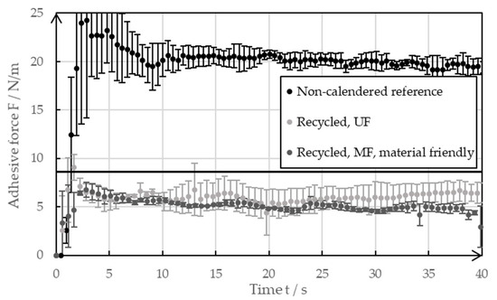
Figure 9.
Adhesive force of the non-calendered negative electrodes with recycled coating, as well as the references with pristine coatings.
The reference coatings dried at room temperature showed exceptionally high adhesive strength, with values reaching 20 N/m. This meant that the adhesive forces were higher than the values of the industrially produced foils of negative electrodes dried at elevated temperatures. This observation is consistent with the results shown by Baunach et al. [20], wherein the minimized binder migration that occurs due to the slow drying leads to increased adhesive forces. For the investigations that were carried out, the reference coated foils were used for the decoating experiments, as shown in Section 3.1. A typical industrial foil of the negative electrode shows lower adhesive forces, even if it is calendered. The high adhesive forces of the reference mean that the ultrasonic decoating of the real electrode residues obtained from industry tends to work even better than what was shown in this paper.
Figure 9 also indicates that the adhesive strengths of foils coated with a recycled paste were lower compared to those coated with a pristine slurry. The lower adhesive strengths suggest that the recycling process may have affected the binder’s integrity. The SBR binder could have partially lost its functionality due to the high shear forces in the ultrasonic bath and the filtration system. Additionally, ultrasonic-induced degradation of CMC is likely to have negatively impacted the adhesive forces, as it promotes the effect of binder migration due to changes of the viscosity. The influence of ultrasound on the paste viscosity is further discussed and evaluated in the rheological measurement section. The effects of binder migration can be seen in the SEM images. The adhesive forces from both recycling rounds ranged between 5 N/m and 8 N/m, with electrodes coated using the recycled paste from the microfiltration (MF) cycle showing slightly lower values. The microfiltration membrane, with a pore size of 1 µm, may have allowed some SBR to pass into the filtrate, reducing its availability in the recycled material to enhance coating adhesion. In contrast, the ultrafiltration membrane pores are too small for SBR loss. Overall, a negative impact of the recycling method on electrode adhesive strength was observed. It is likely that blending recycled material with fresh material could mitigate this effect. Alternatively, adding small amounts of fresh binder might produce electrodes with improved adhesive strength. Subjectively, the adhesive forces of the recycled electrodes were still sufficiently high to handle them similarly to the reference samples.
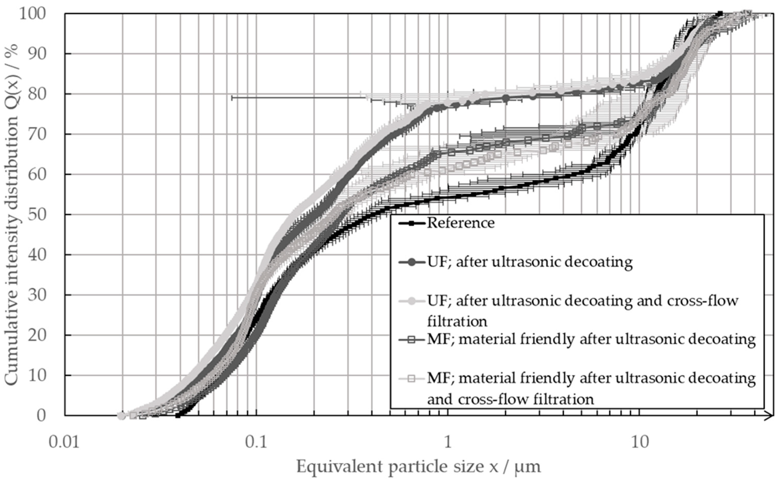
In order to facilitate the direct recycling process and ensure the continued functionality of the recycled materials, it is essential to minimize any alterations to their particle properties. Consequently, the particle size distribution was evaluated following the ultrasonic decoating and subsequent thickening in the cross-flow filter. This approach enabled an evaluation of the influence of both processes on the particle system. Figure 10 illustrates the particle size distributions determined using the LUMiSizer.

Figure 10.
Particle size distribution of a pristine electrode slurry as the reference (black), as well as the slurries after the process of ultrasonic delamination and after the ultrasonic delamination and the subsequent cross-flow filtration with an ultra-filtration membrane (UF) or a micro-filtration membrane (MF).
The determined particle size distributions of the direct recycling passages after decoating and cross-flow filtration were almost identical. Thus, it can be deduced that the cross-flow filtration no longer measurably changes the particle system after the process of ultrasonic decoating takes place. However, the UF and MF passes differed characteristically from the reference. The saddle point of the bimodal distributions of the MF slurries was above that of the reference; in addition, the particles could be measured in the equivalent particle size range between 0.02 µm and 0.04 µm. The saddle point of the distribution from the UF passage was even higher, and the particles could also be measured in the range below 0.04 µm. From the UF passage, the distribution in the equivalent particle size ranged between 0.02 µm and 1 µm, which is characteristic of carbon black, and it is also slightly shifted toward smaller equivalent particle sizes. The differences in the equivalent particle size distributions of the recycled pastes show that the ultrasonic decoating process has a dominant influence on the particle system. After the decoating process, the carbon black agglomerates were more deagglomerated, which was shown by the shift in the particle size distributions in the range characteristic of the carbon black. This could also be seen in the measured particles between 0.02 µm and 0.04 µm, which could not be measured in the reference. That the ultrasonic decoating had a major influence on the carbon black agglomerates was also shown by the fact that the distribution of the slurry obtained in the UF passage deviated excessively from the reference. In comparison, the carbon black agglomerates were altered less in the more material-friendly decoating process of the MF passage. There, the ultrasound only had an impact time on the particle system for 6 h. In contrast, the ultrasound had an effect on the particles suspended in the ultrasound bath for over 45 h during the passage with subsequent UF. The extent to which the deagglomeration of the carbon black had an influence on the performance of the negative electrode still needs to be investigated. However, it was positive that, even after long processing, there was still a large number of larger carbon black structures in the recycling paste. In addition, the direct recycling process had no measurable influence on the graphite structure. The particle size distributions showed no visible change in the particle size range of >5 µm, which is characteristic of graphite. The graphite was, therefore, not excessively grinded by the recycling process.
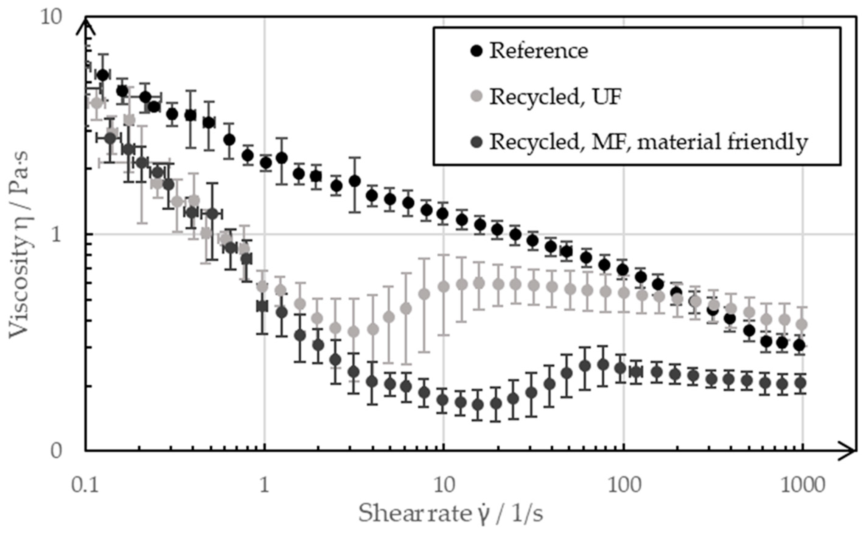
The flow properties are of decisive importance for the coating of a slurry. In order to coat a recycled slurry as part of the manufacturing process of a negative electrode without having to adapt the coating process, the recycled slurries should have similar or the same rheological properties as the pristine reference slurry. Figure 11 shows the flow curves, which were recorded by rheometer, of the slurries resulting from the two recycling processes in comparison to the reference paste, which was recorded before the recycling process.
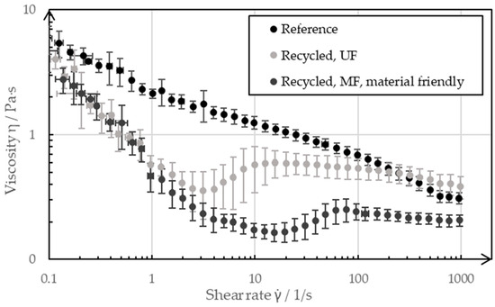
Figure 11.
Rheology of a pristine negative electrode slurry as a reference, as well as the slurries after the different recycling processes.
At low shear rates of 0.1 s−1 and high shear rates of 1000 s−1, the pastes showed only slight deviations from each other, whereas the shear rates between 1 s−1 and 100 s−1 differed more significantly. The reference was shear-thinning over the entire measuring range, whereas the paste from the UF passage was shear-thickening in the range of (3…10) s−1, and it had a lower overall viscosity than the reference slurry. The paste from the MF passage, on the other hand, showed a shear-thickening behavior in the range (20…80) s−1, and this occurred even at lower viscosities than the reference over the measuring range. The rheological properties of the battery pastes of the negative electrode were significantly adjusted by the CMC, which was added to the paste as a diluent during the manufacturing process. The ultrasonic decomposition of the CMC can be seen in the flow curve of the UF passage. As the CMC decomposed, it increasingly lost its properties as a thickening agent; as such, the paste became less viscous. The decomposition of CMC as a water-soluble polymer by means of ultrasound is a known phenomenon and is described in more detail by Gogate et al. [21] and Grönroos et al. [22]. The exact mechanisms through which the degradation of CMC takes place still need to be clarified. Previous studies assume a combination of physical and radical-induced degradation. The recycling step of ultrasonic decoating, thus, has an effect on the molecular size of the CMC and can decompose it. In the recycling pass with the UF membrane, the ultrasound impacted on the CMC dissolved in the bath for several days, which influenced the flow properties of the resulting slurry. In contrast, the ultrasound only had an effect on the CMC for a maximum of 6 h in the pass with the subsequent MF. The fact that the flow curve nevertheless differed more from the reference than that of the UF passage was due to the choice of filter membrane for the subsequent filtration process. The MF membrane with a nominal pore size of 1 µm was permeable to the CMC dissolved in the water, such that a large proportion of the CMC ended up in the filtrate during filtration and therefore no longer influenced the flow properties of the concentrate to the same extent. The decomposition by ultrasound and the filtration of the CMC through a too coarse filter membrane was critical for the recycled paste as the defined flow properties were important for being able to manufacture reproducible, high-quality electrodes. However, the results presented in this paper represent the extreme case of a pure recycled paste without external additives. For the recycling of production scrap with the described process route, it can be advantageous for the quality of the recycling slurry to separate the decomposed CMC with a suitable filter membrane and to adjust the viscosity by adding a new CMC. The decomposed CMC can be separated in the cross-flow filtration process step.
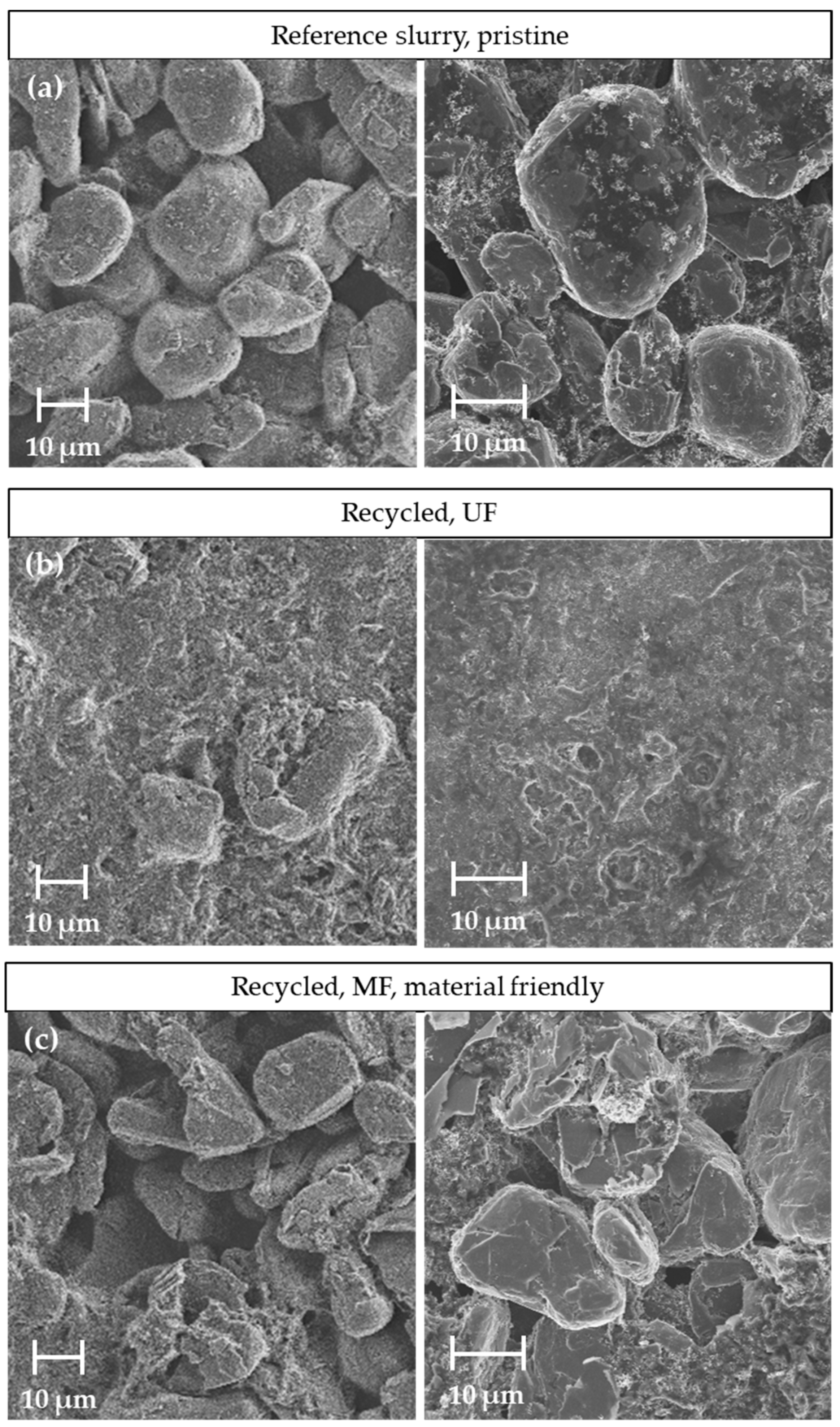
The altered flow properties of the recycled slurries can also influence the coating properties of the dried coating. For this reason, SEM images were taken of the reference coating and the coatings with the two different recycled slurries. Figure 12 shows the top views of the various coatings of the negative electrode.

Figure 12.
Comparison of the SEM analyses for different coated slurries: (a) reference slurry, (b) recycled material processed with the UF membrane and (c) recycled material processed with the MF membrane.
The image of the reference coating (a) shows the spherical particles on which the fine carbon black agglomerates were distributed. The magnification to the right shows the interparticle bridges of the CMC and carbon black between the graphite particles. The images of the coating with the slurry of the UF passage (b), in contrast, show no coarse particle structures. The entire surface was covered with fine carbon black and dried CMC. In a few places in the image, graphite can be seen through the layer. The shapes of these structures are more angular and plate-like than the graphite particles visible in the reference. These observations indicate that the graphite was crushed during the UF recycling pass due to the long exposure time of the ultrasound to the suspension. The reason for the greatly altered surface morphology of the coating, which can be assumed to be the drying behavior of the coating. The CMC decomposed due to the long exposure time of the ultrasound to the suspension of the negative electrode of 45 h in total. This effect has already been described in the discussion of the rheology curves. The decomposed CMC resulted in a more liquid slurry and slower drying, which led to a sedimentation of the graphite in the still wet coating during drying. The graphite particles sediment and exchange were placed with a volume equivalent of water, conductive carbon black and binder. As a result, these were increasingly present on the surface of the coating. During further drying, this resulted in a top layer, which can also be seen in the SEM images. The increased binder migration with more liquid slurries intensified the effect of the top layer formation, as seen in (b). The exposure time of the ultrasound was reduced in the course of the MF. As a result, the CMC was subjected to less stress and the graphite particles were spared. This can also be seen in the SEM images of the coatings produced with the recycled MF slurry (c). The material-friendly process with an exposure time of 6 h on the particle system and subsequent microfiltration produced a coating that can be classified optically between the two coatings described before. The top view shows the spherical graphite particles with local defects in homogeneity and particle morphology. The graphite particles shown in (c) were more angular than those of the reference coating (a). These presumably formed due to the high shear forces in the ultrasonic decoating process or the subsequent cross-flow filtration. On the other hand, there was no evidence of a comprehensive surface layer formation caused by sedimentation and binder migration. Binder and carbon black clusters can only be seen locally on the surface. The extent to which such structures affect the electrochemical properties of the negative electrode must be investigated in the future. It can be assumed that a cover layer as seen in (b) has a rather negative effect on the performance compared to the reference. On the other hand, the material-friendly passage with the MF was expected to have less influence. Current electrochemical investigations indicate that half cells produced with the recycled material show similar performance to the reference.
4. Discussion
The investigations into the decoating of negative electrodes showed that the lowest evaluated ultrasonic frequency works best for cleaning. At a frequency of 29 kHz, more than 95% of an electrode foil can still be decoated if the ultrasonic bath is already thickened with a coating material up to 32.5 wt-%. This process requires an exposure time of 5 min. At frequencies of 40 kHz and 120 kHz, the degree of decoating collapsed even at lower ultrasonic bath mass concentrations. Even with longer exposure times, only a degree of decoating at <95% could be achieved. The comparatively large cavitation bubbles were presumably responsible for the good cleaning at a frequency of 29 kHz. These created highly turbulent micro jets, which broke up the coating and led to a faster dissolution of the CMC in the water of the ultrasonic bath. Further, it broke the interparticle bridges, and the particles were then present in water. At low mass concentrations and long exposure times, care must be taken when using the process of ultrasonic decoating to ensure that the cavitation does not cause pitting of the copper foil. The copper contamination can affect the performance of the recycled electrode paste. Pitting can be effectively prevented by adjusting the exposure time or reducing the power of the ultrasound. Due to the achievable mass concentration in the ultrasonic bath with a simultaneous decoating degree of >95%, this process step can also function as a thickener.
To further remove water from the electrode suspension until it has the same mass concentration as the original negative electrode paste, a suitable process is dynamic cross-flow filtration. With the BoCross system used in this work, an increase in pressure is not suitable for increasing the transmembrane flow and achieving a shorter filtration time. With the system described, the filter pressure can only be increased up to a relative pressure of 5 bar. The pressure increase had no effect on the filter speed. It can be assumed that much higher pressures are required with the UF and MF membranes investigated in order to increase the filtrate flow. In contrast to this, the filtrate flow shows a strong dependence on the rotor speed, which generates a cross-flow at the top of the filter cake. A higher rotation speed results in a stronger cross-flow as the concentrate is forced to flow orthogonally across the filter membrane. The cross-flow results in a reduction in the filter cake thickness and results in a lower filter resistance. The choice of filter membrane has a significant influence on the filter speed and the concentrate. The molecular weight cut-off of the investigated UF membrane (150 kDa) prevents pristine CMC, as the smallest substance in the investigated paste with a molecular weight of 250 kDa, from passing through. This allows high rotational speeds to be run in order to keep the filter cake thickness on the membrane surface small and to reduce the filter resistance. On the other hand, the MF membrane has a nominal pore diameter of 1 µm and can cause carbon black to penetrate into the permeate. To avoid this effect, a cover layer must be built up at low rotational speeds in order to retain the carbon black as an additional filter layer. As a result, lower transmembrane fluxes could be achieved at mass concentrations of the concentrate of up to 27 wt-% than with filtration when using the UF membrane. The speed can only be increased in the course of thickening, as the cover layer also builds up increasingly at higher mass concentrations of the concentrate. As a result, higher transmembrane fluxes could be achieved with the MF membrane from a mass concentration of 27 wt-%. With a pore size of 1 µm, it can be assumed that SBR and CMC, in particular, end up in the filtrate due to their size, and they are therefore lost partially in the MF filtration process.
The investigations described were finally applied to the recycling of negative electrode foils on a technical scale. These differed in the total exposure time of the ultrasound to the particle system and the filtration membrane used in the subsequent process step of the cross-flow filtration. The determination of adhesive strengths using 90° peel tests shows that electrodes made from recycled pastes exhibit lower adhesive forces compared to the reference. Shear- and ultrasound-induced changes in the binders, along with the observed binder migration, are considered the causes for the reduced adhesive strength. Both the paste of the UF and the MF pass were more fluid after the recycling than the reference paste. This can also be seen in the rheology measurements. While, in the UF recycling run, the CMC was destroyed by the long exposure time of the ultrasound and thus lost its utility as a thickening agent, the CMC in the MF run was filtered out through the large filter pore. The decomposition of CMC by ultrasound is a known phenomenon. A combination of radically induced decomposition and mechanical decomposition is assumed to be the reason for this [21,22]. The slower drying speed can lead to binder migration and sedimentation effects during drying. Such observations have already been made in a drying speed study by Baunach et al. [20]. This influences the structure and binder distribution in the dried coating. The mechanical stress also leads to a change in the particle structure of both recycling pastes, which affects the adhesive strength of the coatings. The ultrasonic decoating process mainly causes a change in the particle size reduction. This was confirmed by the measurements of the particle size distributions after the individual process steps. A significant change in the particle size distribution can be seen after the decoating process. The material-friendly recycling pass was, closer to the distribution of the reference. The ultrasound had a particularly deagglomerating effect on the carbon black agglomerates, which seemed to be partially shredded after the step of ultrasonic decoating. The subsequent filtration step did not lead to any significant change in the particle size distribution measured. The aforementioned effects of drying, binder migration and particle size reduction can be seen in the SEM analysis of the coatings. The coating of the UF passage showed a complete top layer of finely dispersed carbon black and binder. Only a few graphite particles could be seen through the top layer. The originally spherical graphite also showed sharp fractured edges. However, the majority of the graphite could not be assessed as it was not visible under the surface layer. In contrast, the SEM examinations of the coating from the material-friendly passage showed significantly fewer changes. The condition was, therefore, also visually closer to that of the reference.
5. Conclusions
The studies carried out enabled an investigation on the influence of the presented recycling route on the material system. The implementation on a technical scale shows that a negative electrode paste can be obtained from 100% recycled material. However, in order to produce a recycled paste that is as pristine as possible, it is advisable to minimize the exposure time of the ultrasound to the particle system. This initially conflicts with the idea of using the ultrasonic bath as a thickener. However, if the aim of recycling is not to recover all materials, then the decomposition of the CMC by ultrasound can be accepted. In the cross-flow filtration process step, this can then be removed with the water using a suitable filter membrane. The flow properties can then be adjusted as required by adding a new CMC to the recycled slurry. This minimizes the effects of the binder migration and particle sedimentation during the drying of the coating, which, in turn, leads to a coating film with improved properties. In order to reduce the mechanical stress on the graphite during ultrasonic decoating, it can be sedimented into a dead zone during decoating. Therefore, it is not exposed to the high load of the ultrasound. It can be assumed that the process time can be significantly reduced by optimizing and automating the decoating and filtration processes. This leads to less stress on all recycled products and to a recyclate that is even closer to the original product. In the future, the electrochemical performance of the recycled coatings will have to be tested. Initial cell formations show promising results. It is planned that these results will be part of an upcoming publication. It should be noted that a mix of recycled and pristine material can also be considered for cell manufacturing. The tests presented and the results therefore represent the exceptional case of a negative electrode produced with 100% recycled material. With the help of a blend, it can be expected that there will be coatings that no one will be able to distinguish from the new negative electrodes of LIBs in terms of electrochemical performance.
Author Contributions
Conceptualization, P.W. and M.G.; methodology, P.W.; validation, P.W., A.H., S.K. and F.G.; formal analysis, P.W., A.H., S.K. and F.G.; investigation, P.W., A.H., S.K. and F.G.; writing—original draft preparation, P.W.; writing—review and editing, P.W. and M.G.; visualization, P.W.; project administration, P.W. and M.G.; funding acquisition, M.G. All authors have read and agreed to the published version of the manuscript.
Funding
We would like to thank the Ministry of Economy, Labor and Tourism of the State of Baden Wuerttemberg for the funding of the project (DiRecFM) Material-efficient recycling of the electrode material of lithium-ion batteries (LIB)—Direct recycling of LIB functional materials (grant no. WM34-42-57/28).
Data Availability Statement
The data that support the findings of this study are available from the corresponding authors upon reasonable request.
Conflicts of Interest
The authors declare that they have no known competing financial interests or personal relationships that could have appeared to influence the work reported in this paper.
References
- European Commission; Joint Research Centre. Supply Chain Analysis and Material Demand Forecast in Strategic Technologies and Sectors in the EU: A Foresight Study; Publications Office: Luxembourg, 2023. [Google Scholar]
- Hettesheimer, T.; Wietschel, M.; Neef, C.; Stijepic, D.; Moll, C.; Thielmann, A.; Tercero Espinoza, L.A.; Joachimsthaler, C.; Meyer, K. Batteriestandort Auf Klimakurs. Perspektiven Einer Klimaneutralen Batterieproduktion Für Elektromobilität in Deutschland. 2021. Available online: https://www.agora-verkehrswende.de/veroeffentlichungen/batteriestandort-auf-klimakurs/ (accessed on 20 March 2024).
- Panasonic Develops New Higher-Capacity 18650 Li-Ion Cells; Application of Silicon-Based Alloy in Anode. Available online: https://www.greencarcongress.com/2009/12/panasonic-20091225.html (accessed on 20 March 2024).
- Wen, J.; Zhao, D.; Zhang, C. An Overview of Electricity Powered Vehicles: Lithium-Ion Battery Energy Storage Density and Energy Conversion Efficiency. Renew. Energy 2020, 162, 1629–1648. [Google Scholar] [CrossRef]
- Bai, Y.; Muralidharan, N.; Sun, Y.-K.; Passerini, S.; Stanley Whittingham, M.; Belharouak, I. Energy and Environmental Aspects in Recycling Lithium-Ion Batteries: Concept of Battery Identity Global Passport. Mater. Today 2020, 41, 304–315. [Google Scholar] [CrossRef]
- Castelvecchi, D. Electric Cars and Batteries: How Will the World Produce Enough? Nature 2021, 596, 336–339. [Google Scholar] [CrossRef] [PubMed]
- Chen, M.; Ma, X.; Chen, B.; Arsenault, R.; Karlson, P.; Simon, N.; Wang, Y. Recycling End-of-Life Electric Vehicle Lithium-Ion Batteries. Joule 2019, 3, 2622–2646. [Google Scholar] [CrossRef]
- Sommerville, R.; Shaw-Stewart, J.; Goodship, V.; Rowson, N.; Kendrick, E. A Review of Physical Processes Used in the Safe Recycling of Lithium Ion Batteries. Sustain. Mater. Technol. 2020, 25, e00197. [Google Scholar] [CrossRef]
- Yao, Y.; Zhu, M.; Zhao, Z.; Tong, B.; Fan, Y.; Hua, Z. Hydrometallurgical Processes for Recycling Spent Lithium-Ion Batteries: A Critical Review. ACS Sustain. Chem. Eng. 2018, 6, 13611–13627. [Google Scholar] [CrossRef]
- Harper, G.; Sommerville, R.; Kendrick, E.; Driscoll, L.; Slater, P.; Stolkin, R.; Walton, A.; Christensen, P.; Heidrich, O.; Lambert, S.; et al. Recycling Lithium-Ion Batteries from Electric Vehicles. Nature 2019, 575, 75–86. [Google Scholar] [CrossRef]
- Kaya, M. State-of-the-Art Lithium-Ion Battery Recycling Technologies. Circ. Econ. 2022, 1, 100015. [Google Scholar] [CrossRef]
- Neumann, J.; Petranikova, M.; Meeus, M.; Gamarra, J.D.; Younesi, R.; Winter, M.; Nowak, S. Recycling of Lithium-Ion Batteries—Current State of the Art, Circular Economy, and Next Generation Recycling. Adv. Energy Mater. 2022, 12, 2102917. [Google Scholar] [CrossRef]
- Lithium-Ionen-Batterie Recycling. Available online: https://www.erdwich.com/einsatzbereiche/lithium-ionen-batterie-recycling/ (accessed on 21 March 2024).
- Recycling of Lithium-Ion Batteries. Available online: https://www.hosokawa-alpine.com/powder-particle-processing/industries/recycling/recycling-of-lithium-ion-batteries/ (accessed on 21 March 2024).
- Scott, S.; Mukherjee, P.; Lei, C.; Hartley, J.M.; Abbott, A.P.; Ryder, K.S. The Effect of Using Alternative Binders and Second Life Graphite Materials on the Electrochemical Performance of Lithium-Ion Battery Electrodes. J. Power Sources 2024, 594, 233993. [Google Scholar] [CrossRef]
- Ren, X.; Tong, Z.; Dai, Y.; Ma, G.; Lv, Z.; Bu, X.; Bilal, M.; Vakylabad, A.B.; Hassanzadeh, A. Effects of Mechanical Stirring and Ultrasound Treatment on the Separation of Graphite Electrode Materials from Copper Foils of Spent LIBs: A Comparative Study. Separations 2023, 10, 246. [Google Scholar] [CrossRef]
- Lei, C.; Aldous, I.; Hartley, J.M.; Thompson, D.L.; Scott, S.; Hanson, R.; Anderson, P.A.; Kendrick, E.; Sommerville, R.; Ryder, K.S.; et al. Lithium Ion Battery Recycling Using High-Intensity Ultrasonication. Green Chem. 2021, 23, 4710–4715. [Google Scholar] [CrossRef]
- Ahuis, M.; Aluzoun, A.; Keppeler, M.; Melzig, S.; Kwade, A. Direct Recycling of Lithium-Ion Battery Production Scrap—Solvent-Based Recovery and Reuse of Anode and Cathode Coating Materials. J. Power Sources 2024, 593, 233995. [Google Scholar] [CrossRef]
- Yildiz, T.; Wiechers, P.; Nirschl, H.; Gleiß, M. Direct Recycling of Carbon Black and Graphite from an Aqueous Anode Slurry of Lithium-Ion Batteries by Centrifugal Fractionation. Energy 2024, 2, 100082. [Google Scholar] [CrossRef]
- Baunach, M.; Jaiser, S.; Schmelzle, S.; Nirschl, H.; Scharfer, P.; Schabel, W. Delamination Behavior of Lithium-Ion Battery Anodes: Influence of Drying Temperature during Electrode Processing. Dry. Technol. 2016, 34, 462–473. [Google Scholar] [CrossRef]
- Gogate, P.R.; Prajapat, A.L. Depolymerization Using Sonochemical Reactors: A Critical Review. Ultrason. Sonochem. 2015, 27, 480–494. [Google Scholar] [CrossRef] [PubMed]
- Grönroos, A.; Pirkonen, P.; Ruppert, O. Ultrasonic Depolymerization of Aqueous Carboxymethylcellulose. Ultrason. Sonochem. 2004, 11, 9–12. [Google Scholar] [CrossRef] [PubMed]

Disclaimer/Publisher’s Note: The statements, opinions and data contained in all publications are solely those of the individual author(s) and contributor(s) and not of MDPI and/or the editor(s). MDPI and/or the editor(s) disclaim responsibility for any injury to people or property resulting from any ideas, methods, instructions or products referred to in the content. |
© 2024 by the authors. Licensee MDPI, Basel, Switzerland. This article is an open access article distributed under the terms and conditions of the Creative Commons Attribution (CC BY) license (https://creativecommons.org/licenses/by/4.0/).