Abstract
The deposition of a thin LixSny alloy layer by plasma vapor deposition (PVD) on the surface of a Li foil is reported. The formation of a Li-rich alloy is confirmed by the volume expansion (up to 380%) of the layer and by the disappearance of metallic Sn peaks in the X-ray diffractogram. The layer has a much higher hardness than bare Li and can withstand aggressive cycling at 1C. Post-mortem scanning electron microscope observations revealed that the alloy layer remains intact even after fast cycling for hundreds of cycles. A concept of double modification by adding a thin ceramic/polymer layer deposited by a doctor blade on top of the LixSny layer was also reported to be efficient to reach long-term stability for 500 cycles at C/3. Finally, a post-treatment after Sn deposition consisting of a plasma cleaning of the LixSny alloy layer led to a strong improvement in the cycling performance at 1C. The surface is smoother and less oxidized after this treatment. The combination of a Li-rich alloy interlayer, the increase in hardness at the electrolyte/Li interface, and the absence of dissolution of the layer during cycling at high C-rates are reasons for such an improvement in electrochemical performance.
1. Introduction
In recent years, there has been a growing need for greater power and energy storage. Lithium metal is considered a promising choice for anode material in the future due to its high specific power and energy. Nonetheless, there are still concerns regarding safety because of the risk of dendritic and mossy Li deposition, which can lead to short circuits and battery malfunctions [1]. Numerous investigations have attempted to address these various issues through methods like passivation and lithium anode modification, which are essential to the development of all-solid-state battery (ASSB) technology. As a matter of fact, the inhibition of dendrite growth is the major concern to be addressed [2]. Various techniques can slow down the growth of Li dendrites, but they are not able to eliminate them.
Among all the modification techniques to passivate the lithium surface, we can mention the deposition of layers of polymer or a polymer/ceramic mix; this is an effective way to reduce dendritic formation [3,4]. Recently, Su et al. showed that an insulative polymer framework (ZIF-8 polyhedrons) is a good strategy to suppress dendritic Li formation [5]. A polymerous PI-ZnO matrix on the lithium surface enhances the electrochemical performance due to the mitigation of dendrite formation [6].
Another method consists of the modification of the lithium surface in solution. In fact, Li metal has a very low negative electrochemical potential (−3.040 V vs. the standard hydrogen electrode) and can easily react with various inorganic/organic molecules [7,8]. Dendrite progression can also be suppressed with layered reduced graphene oxide with nanoscale gaps deposited on the lithium metal anode [9]. Mechanical surface modification is also investigated and this method has been shown to be economical and efficient, along with improving the rate capability [10].
Physical vapor deposition methods such as atomic layer deposition (ALD) and sputtering deposition on lithium foil have been documented using a variety of inorganic compounds and metals [11,12,13,14]. Recently, Bela et al. showed that a coating of Zn on the lithium surface to form an intermetallic coating helps to significantly reduce the instability at the interface [15]. Winter and co-workers showed that the deposition of metals via the sputtering method leads to the formation of lithiophilic layers (Li15Au4 and LiZn) and could suppress lithium dendrite formation during cycling and enhance cycling stability [16]. Sputtering deposition is an efficient method to generate a uniform layer, depending on the deposition parameters. Intermetallic coatings are thin, nanometric, compact, and repeatable, as we demonstrated in a previous study [17]. Furthermore, since this is a dry deposition method, it does not require the use of harmful and costly solvents. In addition, no drying step after modification is needed. Additionally, because deposition is carried out with a high-purity sputtering target in a regulated environment under a high vacuum, contamination during deposition is minimized. Lastly, it could be applied for industrial use as roll-to-roll sputtering machinery for large-scale applications, which is already available and easily adaptable to modify the surface of lithium foils [18,19].
Recently, our research group reported the protection of Li metal foils by depositing a nanometric Zn layer with the aim of fast charging [17]. Since the results were interesting, we tested various metals, such as Ag, Al, Sn, In, Bi, and W. After several months of investigation, it was found that the best results were obtained for the modification of lithium foils with a nanometric Sn layer. Thus, in this work, the protection of the Li metal anode by the deposition of a thin LixSny alloy layer using the PVD technique is reported. A volume expansion of up to 380% was observed following the sputtering deposition of Sn metal. X-ray diffraction (XRD) analyses of modified Li foils revealed the disappearance of Tin peaks, which confirm the in-situ alloying reaction between the lithium anode surface and the freshly deposited Tin. However, the exact composition of the alloy layer is not clearly determined, and it is probably composed of several LixSny alloys. Nanoindentation measurements were conducted on the Li metal before and after the deposition of Sn, and interestingly, a thin layer of LixSny alloy strongly increases the hardness of the anode, which is a desired feature to impede dendrite progression. Post-mortem scanning electron microscope (SEM) observations of used LiFePO4 (LFP)/polymer electrolyte/Li pouch cells showed that the alloy layer remains intact even after fast cycling for hundreds of cycles. No traces of Sn metal were found in the solid polymer electrolyte (SPE) or the Li bulk anode, and the Al additive, initially present in the Li anode, is still uniformly distributed inside it, even after repetitive cycling at high C-rates.
A few years ago, we also demonstrated the interest of a thin ceramic-rich polymer layer deposited on Li foil to reduce the progression of Li dendrites and to decrease the charge transfer resistance between the Li anode and the polymer electrolyte [20]. In order to obtain a cumulative effect, a concept of double modification by adding a thin ceramic/polymer layer deposited by a doctor blade on top of the LixSny layer was also reported in this paper. This concept permits to run an LFP/SPE/Li battery at C/3 for 500 cycles with a capacity retention of 92.6%, corresponding to a discharge capacity of 150 mAh·g−1. Finally, to wash the surface of the Sn deposit on top of the Li metal, a plasma cleaning was applied, and the alloy layer was found to be smoother and less oxidized. Consequently, this treatment led to a strong improvement in the cycling performance at 1C, and the cell was able to perform 300 cycles, which represents an improvement of 1000% in comparison to the reference cell assembled with the pristine Li metal anode.
2. Materials and Methods
2.1. Sputter Deposition of Tin on Li Metal Surface
Hydro-Quebec produces its own in-house Li metal foil, with a thickness of 50 µm and containing 0.2% Al additive. The sputter machine used to deposit Sn metal is the EM ACE600 table-top model from Leica Microsystems Inc. (Concord, ON, Canada). To clean the sample surface, it is equipped with a glow-discharge option. All Sn metal targets (purity of at least 99.999%) were purchased from American Elements (Los Angeles, CA, USA). A special holder has been designed to fix the Li foil in front of the target in the deposition chamber. The process starts with six sequences of vacuuming up to 0.008 Pa to remove air traces. The chamber was refilled with highly pure Ar (grade 6.0, 99.9999% purity) between each vacuum sequence. Before deposition on the Li surface, a cleaning of the Sn target is carried out, which consists of applying 70 mA for a 30 s pre-putter. All the sputter depositions were performed using an Ar pressure of 0.8 Pa, and the sample holder realizes 20 rotations every minute. The plasma is created at the Sn target surface by applying a DC current of 50 mA (34 W). Finally, a fixed distance of 45 mm is used between the Li metal foil and the target, and the tilt angle is set to 0°.
2.2. Plasma Cleaning of Sn-Coated Li Metal Anodes
The Sn deposit on the Li surface was also treated with plasma in order to clean it and remove some oxygen contamination. The process is realized just after the Sn deposition in the same chamber and without exposure to dry air. To do this, plasma is created on an inox plate by applying a DC current of 15 mA to it. The plate is placed in front of the Li foil to perform a plasma cleaning of the surface for 15 min. As for the Sn deposition, the cleaning process is performed under a pressure of 0.8 Pa in an inert atmosphere of Ar.
2.3. Deposition of a Polymer/Ceramic Layer on Sn-Coated Li Metal Anodes
Allyl-ether branched polyethylene oxide polymer (PEO, m.w. ~100,000) was mixed with Lithium bis(trifluoromethanesulfonyl)imide salt (LiTFSI from Sigma-Aldrich, Oakville, ON, Canada) in tetrahydrofuran solvent (THF) respecting an O:Li molar ratio of 5:1. A small quantity of Omnirad 651 photoinitiator (0.4 wt.%, IGM resins, Charlotte, NC, USA) was added into the polymer solution. The viscous liquid was mixed until a clear solution was obtained. Then, 300 wt.% of Al2O3 ceramic (AKP-G015, Sumitomo Chemical Co., Ltd., Tokyo, Japan) [21] was added to the polymer solution. The mixture was intensively mixed with an ULTRA-TURRAX rotor-stator generator. Anhydrous THF was added dropwise to obtain a solution with a solid content of ~30%. The ceramic-rich solution was deposited on a Li foil using a doctor blade in order to yield dry polymer films with a thickness of 3–4 µm. The ceramic-coated Li stripe was placed under a ventilated hood for 5 min and subsequently placed inside a box filled with nitrogen. The Li foil is then exposed to UV radiations for 5 min.
2.4. Preparation of LiFePO4 Electrodes
The composition of LFP electrodes consisted of 75.3 wt.% of carbon-coated active material (LFP), 19.23 wt.% of PEO polymer, 6.27 wt.% of LiTFSI salt, and 1 wt.% of carbon black. All of these ingredients were thoroughly mixed using a mixture of acetonitrile (80% in volume) and toluene (20% in volume). The slurry was deposited by the doctor blading method on a carbon-coated aluminum foil (thickness of 15 µm). After drying, an active mass loading of ~8 mg·cm−2 is obtained. The whole process was realized inside a dry room having a dew point of less than −50 °C.
2.5. Preparation of the Solid Polymer Electrolyte
Allyl-ether branched PEO polymer was mixed in presence of a small amount of an acetonitrile/toluene (80:20 v/v) solvent mixture. When a viscous solution was obtained, LiTFSI salt was added in order to obtain an O:Li molar ratio of 25:1. Then, 0.4 wt.% of Omnirad 651 photoinitiator was dispersed in the salted polymer solution. Finally, the solution was mixed and regularly degassed to obtain a bubble-free solution.
The as-prepared polymer solution was cast on a polypropylene film by using a doctor blade. The doctor blade gap was adapted to the viscosity of the solution and to obtain a dry SPE with a thickness of 25 µm. Then, the dry film was placed in a sealed box, which was purged with dry nitrogen for at least 3 min. The coating was allowed to reticulate by exposing it for 5 min to an UV light (300 WPI) placed at 50 cm.
2.6. Assembling of Pouch Cells and Electrochemical Tests
The cells assembling process is conducted in a well-controlled dry room having a dew point <−50 °C. LFP/SPE/Li batteries are assembled at 80 °C under vacuum for 3 min using a hot-press. The active surface area for the anode and the cathode is ~7.48 cm2. The LFP/SPE/Li stackings are placed in an in-house casing for applying an isostatic pressure of 75 psi. The reference cell is using an unmodified Li metal anode.
The cycling of all the batteries was realized at 80 °C with BioLogic BCS-815 potentiostats. Before long cycling experiments at 1C–C/2 or C/3–C/3 (charge–discharge currents), the cells performed two formation cycles at C/12. Considering the loading of the cathode, 1C is approximately equal to 0.9 mA·cm−2. A potential window of 2.0 to 3.8 V vs. Li/Li+ was fixed for the electrochemical evaluation.
2.7. Characterizations
Grazing incident angle X-ray diffraction (GIXRD) was used in characterizing Sn thin films coated on lithium and silicon substrates with Smartlab (Rigaku, CoKa radiation) in a controlled environment to avoid Li metal oxidation. Data were collected at an incident angle of 0.5° for 10 h. The surface of the analyzed sample is ~15 × 15 mm2.
Optical images are obtained with a Keyence VK-x200 3D laser microscope (Itasca, IL, USA).
An atomic force microscope (AFM, Bruker Dimension Icon model, Etobicoke, ON, Canada) was utilized to study the surface of Sn deposits on Li metal. The QNM mode coupled with silicon nitride tips was employed. The spring constant of the cantilever was 5 N/m. A scan rate of 0.50–0.97 Hz was selected, and the resolution was 512 samples/line.
Cross-section views of LFP/SPE/Li stackings extracted from pouch cells before or after cycling were observed using a Hitachi SU-7000 scanning electron microscope (hitachinaka, Japan). In order to detect Li X-ray [22], the microscope was equipped with an EDS windowless detector Oxford Instruments Ultim Extreme. Samples were manipulated in a dry room, in which the microscope was placed to avoid external contaminations and reactions between Li metal and water. The micrograph and X-ray map were acquired at an accelerating voltage of 5 kV. The working distance was 9 mm, and the probe current was 500 pA.
Nanoindentation curves of various depositions on lithium were obtained with an Anton Paar HIT (Montreal, QC, Canada). A Berkovitch diamond indenter was used. A typical run was performed at 1 mN and 1.5 mN/min. A creep of 40 s and a return in 20 s complete the run. The hardness was calculated using load and plastic deformation in Equation (1):
where H = hardness in Pa, P = pressure in N, and A = surface in m2.
H = P/A,
3. Results and Discussion
3.1. Formation of an Alloy Layer on Li Surface during Deposition of Sn
Sputter deposition of Sn was performed at the same time on the surface of a lithium foil and a piece of silicon, as shown in Figure 1a. Theoretically, 400 nm of tin was deposited on the surfaces of the two substrates. After deposition, the thickness is verified using microscopic observations of the substrate edge. Figure 1c shows a SEM image of the silicon piece, and the measured thickness is consistent with the expected theoretical thickness; on average, a value of 0.37 μm was obtained. Regarding the deposition of 400 nm of Sn on the Li surface, the measured thickness is much greater than the theoretical thickness. Indeed, as shown in the SEM image of the Li foil (see Figure 1d), the thickness, although relatively uniform, is between 1.4 and 1.5 μm, and on average, a thickness of 1.41 μm was obtained, which represents an expansion of about 380% compared to the theoretical value (see Figure 1b). This expansion is attributed to the formation of a Li-rich LixSny alloy, and its value is close to that reported, for example, for an alloy such as Li4.4Sn (i.e., 360%) [23].
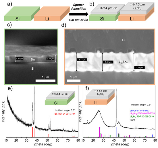
Figure 1.
(a) Pieces of Li and Si are placed next to each other to deposit at the same time 400 nm of theoretical Sn by sputtering. (b) Schematic representation of the thicknesses of the layers obtained after deposition of 400 nm of Sn. While the thickness of Sn on Si is close to the theoretical value, a much thicker Sn-containing layer is clearly observed on Li substrate (about 380%) due to the formation of Li–Sn alloys. Scanning electron microscope images showing the edge of (c) silicon and (d) lithium substrates with the Sn deposit on top. Grazing angle (0.5°) X-ray diffractograms for (e) Si substrate and (f) Li foil, after deposition of 400 nm Sn by sputtering.
To confirm the presence of a Li-rich Sn alloy, GIXRD analysis was performed on the Li–Sn-protected Li foil as well as on the Si substrate. Figure 1e presents the GIXRD pattern obtained with a grazing angle of 0.5° for the Si substrate covered with 400 nm of Sn. As expected, only peaks for Sn metallic were observed (PDF powder diffraction file number: 04-004-7747). In addition, no metallic oxides/nitrides (e.g., SnO, Sn3N4) or LixSny alloys are detected that could be attributed to contamination with oxygen/nitrogen in the gas or Li metal vaporization in the chamber. In contrast, when Sn metal is deposited on the Li metal surface, the XRD pattern totally changes, as evidenced in Figure 1f. First, Li metal peaks are detected (PDF powder diffraction file number: 01-071-9473) and attributed to the Li foil itself. Just after deposition, it is worth noting that Sn metal peaks are not detected, confirming that a chemical reaction occurred between Sn atoms and Li metal. In fact, broad low-intensity peaks are detected, especially those centered at 25 and 45°. The composition was tentatively attributed to Li13Sn5 (PDF 04-007-2035) and Li5Sn2 (PDF 00-029-0839) phases with very small crystallite sizes, or the deposit could be mainly amorphous with an undefined chemical composition. According to the Li–Sn binary-phase diagram, these two phases can be obtained at room temperature [24]. Serikkazyyeva et al. reported the fabrication of a Li/LixSny thin anode film on a copper foil by alternating depositions of Sn with magnetron sputtering and Li metal with thermal evaporation [25]. Using XRD analysis, they also confirmed the presence of the Li5Sn2 alloy and Sn that had not reacted. Although doubt exists concerning the exact composition of the layer after Sn sputtering, the chemical reaction between Sn and Li metals is consistent with the increase in thickness observed.
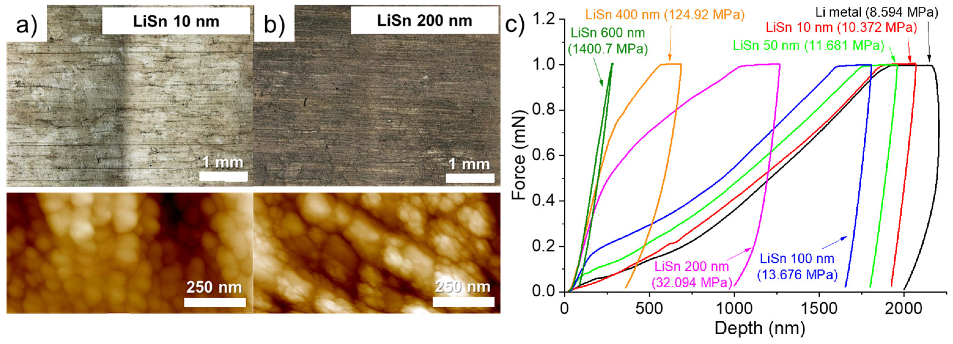
The volume expansion related to the formation of an alloy is also visible by observing the surface of the lithium modified with two different thicknesses of Sn. The surface of the lithium foil covered by 10 (Figure 2a) and 200 nm (Figure 2b) of Sn is compared using confocal and atomic force microscopes. First, by depositing thin thicknesses, typically less than 100 nm, a visual difference in color is observed between the different Li grains (see confocal image in Figure 2a). In a previous study dealing with Zn layer deposition, a similar observation was also made, and the crystalline orientation of the Li grains was suspected to have an impact on the structure of the deposit [17]. Darker grains contain more “holes” on the surface. One of these holes is clearly visible, for example, in the AFM image in Figure 2a. As the thickness of the Sn deposit increases, the holes gradually close, and the color difference between the Li grains gradually disappears. Thus, the confocal image of the 200 nm-thick Sn deposit on the surface of lithium appears more uniform and darker (see confocal image in Figure 2b). The AFM image of the lithium surface with the 10 nm-thick Sn deposit shows the formation of small spheres of about 50 nm. As tin deposition takes place and the formation of the LixSny alloy occurs, the spheres grow into a cauliflower shape, and the holes are thus filled. The AFM image in Figure 2b shows that the surface is covered with cauliflower-like structures. Bela et al. recently reported something very similar during the thermal evaporation of Zn on the surface of a Li foil [15].
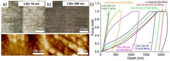
Figure 2.
Confocal optical images (top) and 2D atomic force microscope images (bottom) for the Li metal surface after deposition of (a) 10 and (b) 200 nm of Sn. (c) Nanoindentation curves obtained on the surface of the Li metal foil (black) and for pieces of Li metal that have been coated with 10 nm (red), 50 nm (light green), 100 nm (blue), 200 nm (purple), 400 nm (orange) and 600 nm (olive green) Sn. The hardness value is shown in parentheses. All thicknesses mentioned are theoretical and not measured.
According to them, the high roughness for thin metal deposits can be explained by the growth mechanism described by the island growth model (Volmer-Weber model). In short, as the thickness of metal increases, a stronger metal-metal interaction than Li-metal interaction is obtained, which causes the formation of islands and apparent voids within the coating. When the thickness of metal is still increased, the islands intergrow with each other and form a continuous coating with a corrugated morphology due to the volume expansion. However, this explanation partially fit with what observed by us, since some Li grains did not present these holes upon Sn deposition. On the other hand, upon Sn deposition, the cauliflower-like structures are observed everywhere on the surface of the Li foil. That means the Li-rich alloy is formed on the whole surface, but the holes depend on the Li grain orientation for a reason that must be clarified.
Hardness measurements were conducted on the surface of the bare Li foil and after deposition of various thicknesses of Sn. Nanoindentation curves were obtained by imposing a constant force of 1 mN and the hardness was obtained by calculation using the load and the plastic deformation. To ensure good reliability, several measures (at least 15) were realized on each sample and the average curve is used for calculation of the hardness. An example in Figure S1 (Supplementary Materials) presents 17 measurements (black lines) and the average curve in red for a piece of lithium metal that has been cleaned with plasma for 10 min and covered with a 50 nm layer of Sn. As seen, all measurements are close to each other, and the hardness calculated from the average curve is a good representative of the sample. The average indentation curves for Li metal anodes with various thicknesses of Sn are presented in Figure 2c. For the pristine Li metal, a hardness value of about 8.6 MPa is calculated. This value slowly increases with the thickness of Sn to reach ~13.7 MPa for a deposit of 100 nm (+159% in comparison to the bare Li anode). As the thickness of Sn increases, the hardness value sharply increases. Thus, deposits of 200, 400, and 600 nm led to an increase of 373, 1454, and 16,300% of the hardness, respectively. Especially for deposited thicknesses of 400 and 600 nm, the hardness of such small alloy interlayers is interesting to counteract the progression of Li dendrites, as long as the Li+ ions stripping/plating take place on the Li side, between the LixSny layer and the Li bulk anode. Then, for the electrochemical evaluation with abusive cycling protocols (fast charging of 1C and long-term cyclability at C/3) it was decided to study the influence of Sn deposits of 400 and 600 nm. It is worth noting that after screening several metals (see Figure S2 in the Supplementary Materials), for the deposition of 400 nm, Sn metal gave the higher hardness (124.9 MPa) in comparison to Ag (19.8 MPa), Bi (23.0 MPa) or Zn (33.9 MPa). However, it was found a bimetallic deposition of Sn/Ag (75%/25%) led to a higher hardness value of 785.3 MPa but this solution was not thoroughly studied due to high cost of silver.
3.2. Evolution of the Deposited Layer during Battery Assembly and Cycling
3.2.1. LFP/SPE/Li Battery Stack after Assembling
In our previous study dealings with the deposition of Zn on Li metal anode [17], we observed the formation of AlZn nanoparticles into the bulk of the Li metal anode after cycling at 1C for several cycles until death of the batteries. A complete dissolution of the nanometric Zn layer was also observed. At this time, it was suggested to conduct post-mortem SEM analyses after different stages of cycling to understand the various steps consisting of Zn layer dissolution and AlZn nanoparticles formation. Similarly, it was proposed in the present study to observe LFP/SPE/Li battery stacks assembled with Sn-protected Li anodes just after assembling, after one charge at C/40 and after several cycles at 1C in charge.
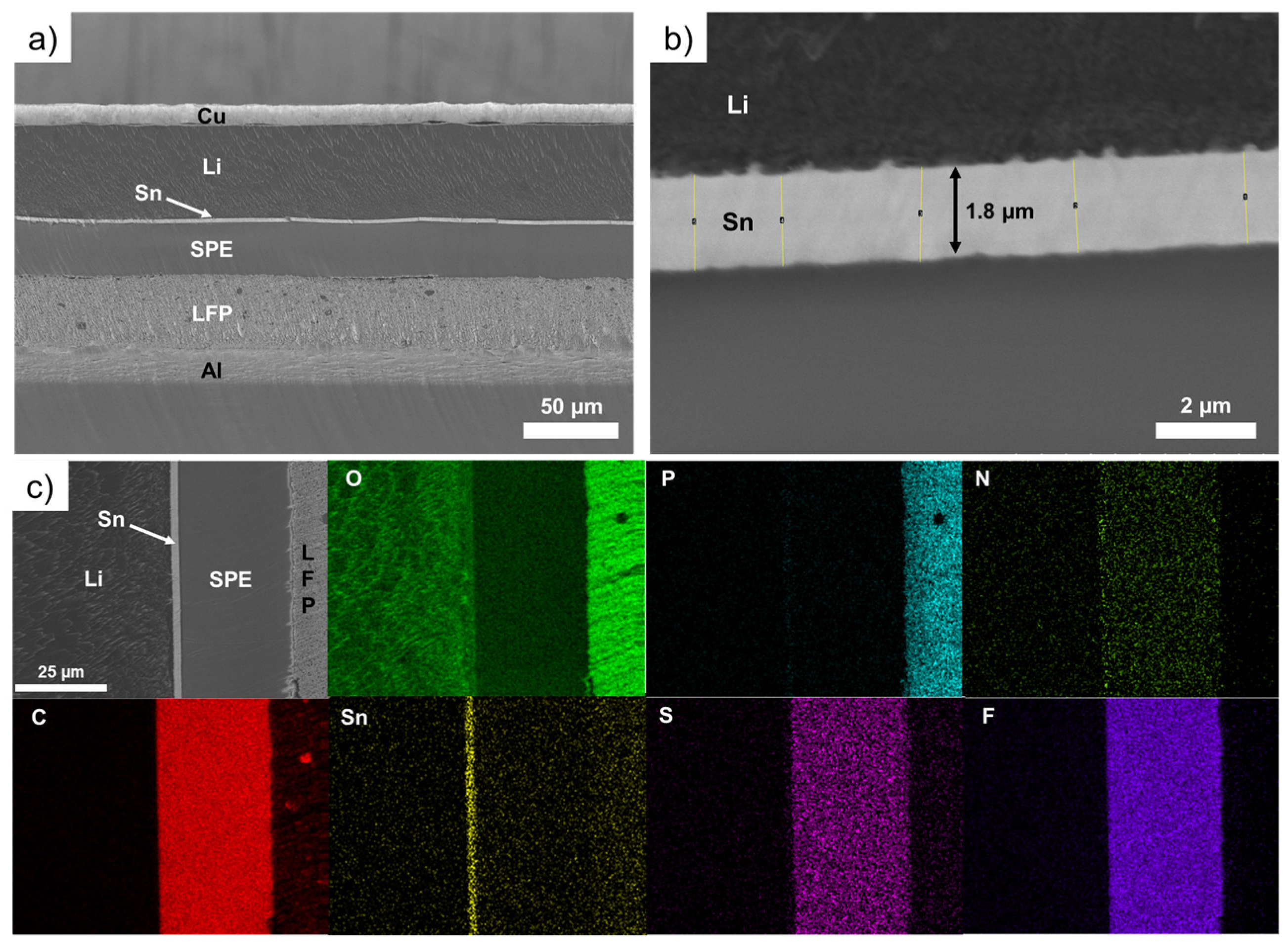
Figure 3 shows SEM images of an LFP/SPE/Li battery stack after assembling using a Li foil with a theoretical Sn layer of 600 nm. In addition, the chemical mapping of the battery stack for various elements is presented. In the Figure 3a, the thin and compact layer of tin can be easily seen between the Li metal and the SPE. The magnification in Figure 3b shows the layer of Sn have a thickness of about 1.8 µm (the same thickness is measured after deposition of 600 nm of Sn), which represents a volume expansion of 300% in comparison to the theoretical value of Sn deposited (i.e., 600 nm). Above, we demonstrated that for thinner deposits of Sn, the expansion could be up to 380%. For better clarity, Table 1 reports the evolution of the LixSny layer thickness as a function of different conditions of deposition (400 nm vs. 600 nm) and cells assembling/cycling. It was found that the thicker the deposit of Sn on Li metal, the lower the volume expansion. That could be explained by the limitation of Li diffusion inside the layer of Sn. As the thickness of Sn increases, the Li metal hardly diffuses inside the metallic layer and the volume expansion gradually decreases. This can be seen by the difference in the color of the deposits. For thin deposits, a gold color is obtained and as the thickness of Sn increases, a grey deposit is observed that is more likely due to the presence of unreacted Sn metal (see photographs of pristine and modified Li metal foils with 600 nm of Sn in Figure S3). This was evidenced by Serikkazyyeva et al. that confirmed the presence of unreacted Sn metal in their 1000 nm-thick Li/LixSny anode made by the thermal evaporation of Li and sputtering of Sn [25]. It is worth noting that, at this stage, although slightly visible, small particles are generated at the boundary between Li and Sn metals. These particles are already observed after the deposition of Sn on Li foil (see Figure 1d) without assembling the cell. Their composition will be discussed below.

Figure 3.
(a) Scanning electron microscope image of an LFP/SPE/Li battery stack after assembling using a Li foil with a theoretical Sn layer of 600 nm. (b) Zoom on the interface between the Li metal and the solid polymer electrolyte showing a 1.8 μm tin layer. (c) Chemical mapping of the battery stack for various elements: O, P, N, C, Sn, S and F.

Table 1.
Evolution of the LixSny layer thickness as a function of different conditions of deposition (thickness of Sn deposited) and cells assembling/cycling. A theoretical value of expansion for Li4.4Sn alloy is given for comparison.
The chemical composition of the LFP/SPE/Li battery stack after assembling is presented in Figure 3c. The thin Sn layer is easily evident on the chemical mapping of Sn. It is also clear that no diffusion of Sn metal inside the Li bulk or into the SPE after assembling is observed. In addition, at this stage, no pollution with another element, such as oxygen for instance, is detected.
3.2.2. LFP/SPE/Li Battery Stack after One C/40 Charge
To demonstrate the utility of the intermetallic layer as a strong barrier against Li dendrites and to favor the uniform electrodeposition of Li metal on its side facing the bulk Li anode, it was proposed to slowly charge the battery at C/40 (the galvanostatic charge profile is shown in Figure S4) and observe what happens at the Li/Sn and Sn/SPE interfaces. Firstly, the SEM image presented in Figure 4a shows that the layer is still intact after one charge except the thickness slightly increased from 1.8 (see Table 1 and Figure 3b, cell after assembling) to 2.0 µm. As discussed above, it was suggested that the lithiation of the Sn layer was not complete. Thus, after one charge of the battery, the lithiation is improved, and an increase in the thickness is observed. However, an expansion of 330% of the Sn layer thickness is calculated, which means the lithiation is not complete after one slow charge (see Table 1). Considering the charge capacity obtained (about 160 mAh/g, see Figure S4) and the cell dimensions, approximately 4.1 µm of fresh Li metal is deposited on the Li anode during the slow charge process at C/40. Since the thickness of the LixSny interlayer only increased from 1.8 to 2.0 µm, most Li metal electrodes are deposited between the Li anode and the Sn layer.
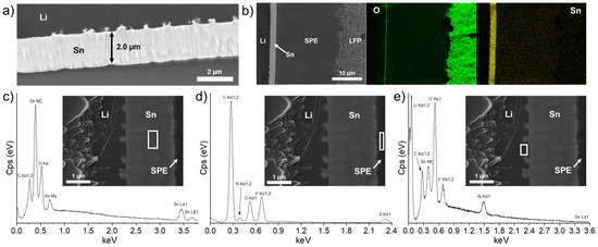
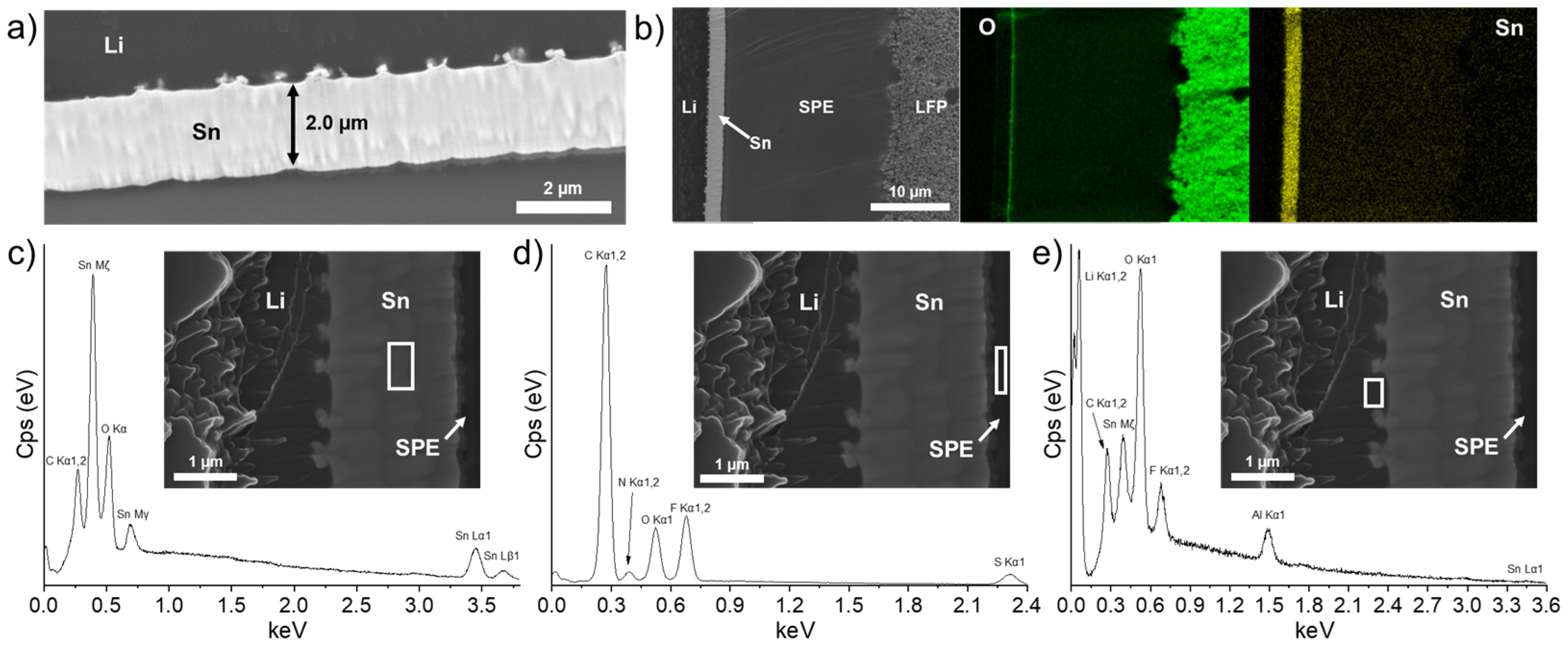
Figure 4.
(a) Scanning electron microscope image showing the thin Sn layer for an LFP/SPE/Li battery assembled with a Li foil with a theoretical Sn layer of 600 nm and after performing a charge at a C/40 rate. (b) Chemical mapping of the battery stack for O and Sn elements. Energy dispersive X-ray spectra for (c) the tin layer, (d) the zone inside the solid polymer electrolyte near the Sn layer, and (e) the zone inside the Li metal near the Sn layer. The white rectangle in each scanning electron microscope image indicates where the energy dispersive X-ray spectrum is recorded.
In addition, the growing of particles at the Li/Sn interface is more visible in comparison to the cell after assembling (see Figure 3b). Another observation is the apparition of an oxygen-rich layer on the Sn layer that is in contact with the SPE. This nanometric layer is visible on the oxygen mapping of Figure 4b. The reason for its apparition remains unclear and could be attributed to an oxidative phenomenon of the Sn layer in contact with the SPE. More importantly, the dense LixSny alloy layer resists the charge without any sign of dissolution. As put in evidence by the energy dispersive X-ray (EDS) spectra and SEM images presented in Figure 4c–e, the Sn layer remained intact and is mostly composed of Sn metal. The chemical composition of the SPE near the Sn layer (see the analyzed area delimited by the white rectangle in Figure 4d) revealed the presence of atoms that are normally expected for the SPE, but the absence of Sn metal demonstrated that the layer is stable upon cycling. As mentioned, some particles are formed progressively at the Li/Sn interface. At this moment, their nature remains uncertain. The EDS spectrum in Figure 4e shows the chemical composition at the Li/Sn interface. Al metallic is initially present in the Li bulk anode as an additive and is thus normally detected. Fluorine, carbon, and oxygen are mostly attributed to contamination with the SPE during sample preparation. Sn metallic is detected, which confirms that the freshly formed nanoparticles are at least composed of Sn from the initial layer. More importantly, after one charge, the fresh Li+ ions from the cathode migrate through the SPE to electroplate on the initial Li anode. In fact, the Sn/SPE interface remains intact with no traces of Li agglomeration, and the Sn layer seems dense with a homogenous composition, confirming that the Li metal from the cathode is deposited on the anode side. This demonstrates the role of a Li-metal alloy layer to act as a barrier against dendrites due to its higher potential [26,27] and hardness (see Figure 2c) than Li metal.
3.2.3. LFP/SPE/Li Battery Stack after Long-Cycling at 1C in Charge
LFP/SPE/Li pouch cells were assembled with the Li anode modified with 600 nm of sputtered Sn metal and cycled until the death of the battery. Figure 5a shows the typical charge/discharge profile (104th cycle as an example) for the battery cycled at a rate of 1C–C/2. A reversible plateau at ~3.45 V vs. Li/Li+ is obtained that corresponds to the electrochemical activity of Fe3+/Fe2+ in association with the insertion/disinsertion of Li+ ion in the olivine structure of LiFePO4 [28]. This indicates that the thin lithiated Sn layer does not have an impact on the overall potential of the electrochemical system, probably due to its small thickness in comparison to the bulk anode (25 times larger in this example). In fact, it is known that LixSn alloys have redox potentials that could be comprised between 0.38 (Li-rich alloys) and 0.78 V (Sn-rich alloys) depending on the composition [27,29]. Thus, in addition to providing a physical barrier against dendrites, this artificial alloy layer could reduce or inhibit the degradation of solid-state electrolytes, such as halides [30,31] or sulfides [32], due to its higher potential than Li metal. Figure 5b,c show the discharge capacities (C/2) and the corresponding Coulombic efficiencies for batteries of reference (black) and using the anode with a theoretical Li–Sn alloy layer of 600 nm (green). Firstly, the reference cell delivered about 162 mAh·g−1 during discharge at C/2, which is near the theoretical capacity of the LFP cathode material (~170 mAh·g−1) [33]. However, the cell was not able to run at 1C–C/2 for more than 30 cycles. As seen in Figure 5c, a drop of the Coulombic efficiency is observed that is associated with a long plateau during the charge that reveals the formation of Li dendrites at a high cycling rate [17]. This observation as well as the apparition of “voltage noise” are typical of micro-short circuits [34]. Due to the contact between the cathode and the anode, during the charge, a higher capacity than the theoretical one is recorded. In fact, the delithiation process of the LFP cathode is counter-acted by its dendritic lithiation [35]. The reference cell was disassembled after failure and the electrodes were observed visually and with a confocal microscope. Figure 5d,e show photographs of the LFP/SPE/Li reference stack observed from (d) the Li side and (e) the cathode side. Bubbles are visible on the Li side after the cell is short-circuited, and a detachment of the cathode coating on the cathode side is clearly observed. These bubbles are generated by side reactions occurring when the Li metal touches the cathode. This is confirmed by a closer look at the surface inside the detached area (Figure 5f). A spot, delimited by a yellow circle, is observed with a confocal microscope, and the image is presented in Figure 5g. Cracks in the cathode film were observed, which confirms gases have been released in this area. In addition, fresh Li metal from the Li anode is also observed, which proves Li dendrites penetrated the SPE to short-circuit with the cathode.
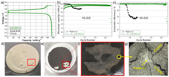
Figure 5.
(a) Charge/discharge curves (1C–C/2) corresponding to the 104th cycle for the battery assembled with a Li modified by a Sn layer with a theoretical thickness of 600 nm. (b) Discharge capacities (charge 1C–discharge C/2) and (c) Coulombic efficiencies for batteries of reference (black) and using an anode with a theoretical Li–Sn alloy layer of 600 nm (green). Photographs of the LFP/SPE/Li reference stack observed from (d) the Li side and (e) the cathode side after cycling at 1C–C/2 (charge–discharge) until death of the cell. (f) Magnification of the detached area. (g) Confocal image of the area inside the yellow circle shown in (f), where fresh Li from the Li anode has penetrated the SPE to short-circuit with the cathode.
For the cycling of the cells with the Li–Sn-protected anodes, the initial discharge capacities are lower in comparison to the reference cell. It took several dozens of cycles to stabilize and reach about 155–160 mAh·g−1. However, the Coulombic efficiencies are near 100% and this behavior is much more attributable to the initial resistance of the dense Sn layer to rapidly diffuse Li+ ions. As discussed above, the theoretical 600 nm-thick layer of Sn is not totally lithiated (i.e., only 300% of volume expansion after deposit and the grey color of the surface, see Figure S3) and even after a slow charge, it did not seem fully lithiated (expansion of 330% only). The two cells were able to run correctly for 210 and 225 cycles, which represents a significant improvement in comparison to the reference cell with a longevity increase by a factor of 7.5.
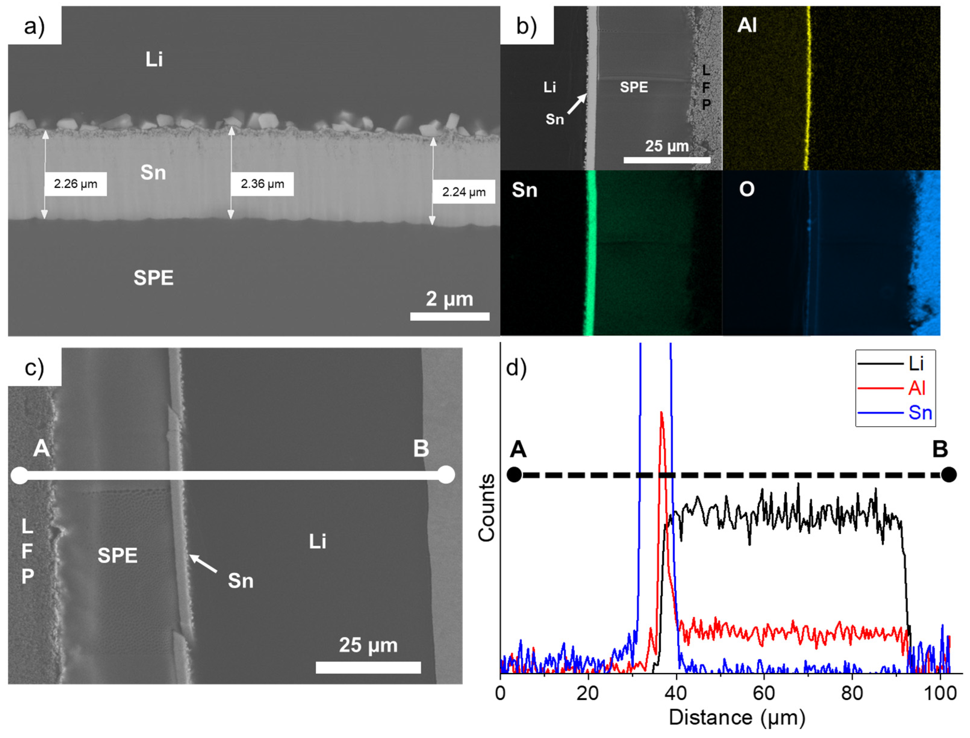
The cell that performed for 225 cycles was opened and the cross-section of the LFP/SPE/Li stack was observed with a SEM. Figure 6a shows that the Sn layer is mostly intact and dense even after harsh conditions of cycling. Its thickness slightly increased to an average value of 2.29 µm, which represents an expansion of 380% (see Table 1), as previously calculated for thinner Sn deposits (Figure 1d). Secondly, the square-shaped nanoparticles formed at the Li/Sn interface are larger but did not seem to migrate into the Li bulk anode, contrary to former observations made with Zn coatings on Li metal [17]. Using the same deposition method, we found that after few cycles at 1C, the thin Zn layer was totally dissolved into the Li bulk anode and plenty of AlZn nanoparticles were formed and uniformly distributed into the anode. Bela et al. also confirmed the progressive dissolution of their Zn coating made by thermal evaporation on Li metal. The chemical mapping presented in Figure 6b shows that the nanoparticles are also rich in Al metal, which is originally present in the Li anode as an additive. This AlSn layer is very thin and dense after 225 cycles at 1C and interestingly the remaining aluminum is uniformly distributed into the Li bulk anode. Thus, during cycling, the small nuclei of Sn formed on the Li side are enriching in Al. Probably because the solubility of Sn in Li is less important than in the case of Zn metal, the particles remain at the Li/Sn interface and slowly grow upon cycling. This is another important aspect for the designing of protective layers on Li metal: the layer must be stable upon cycling. It is one of the reasons why electrochemical performances are so improved in comparison to the reference cell. At this stage, we have demonstrated that our alloy layer is too dense and thin to impact the energy density of the electrochemical system; the in-situ generation of a 3D Li-rich alloy favors the fast Li+ ion transfer at the SPE/Sn interface; and the chemical and electrochemical stabilities of the artificial layer permit cycling of the battery at high C-rates for several hundreds of cycles.

Figure 6.
(a) Scanning electron microscope image of the LFP/SPE/Li battery after performing 225 cycles at 1C and showing the intact thin Sn layer. (b) Chemical mapping of the battery stack for the following elements: O, Al, and Sn. (c) Scanning electron microscope image of the LFP/SPE/Li battery after cycling for 225 cycles at 1C. The chemical composition is recorded along a line from point A to point B. (d) Chemical composition profile along the A–B line for the following elements: Li, Al, and Sn.
The chemical composition for Li, Al, and Sn was recorded along a line from point A to point B in the SEM image presented in Figure 6c. The corresponding chemical composition profile, shown in Figure 6d, demonstrates that no dissolution of Sn was observed in the Li bulk anode or inside the SPE. An accumulation of Al is effectively present at the Li/Sn interface and, as said above, the remaining Al additive is uniformly distributed into the Li bulk anode.
3.3. Overcoating of a Polymer/Ceramic Layer on the Surface of the Li–Sn Foil
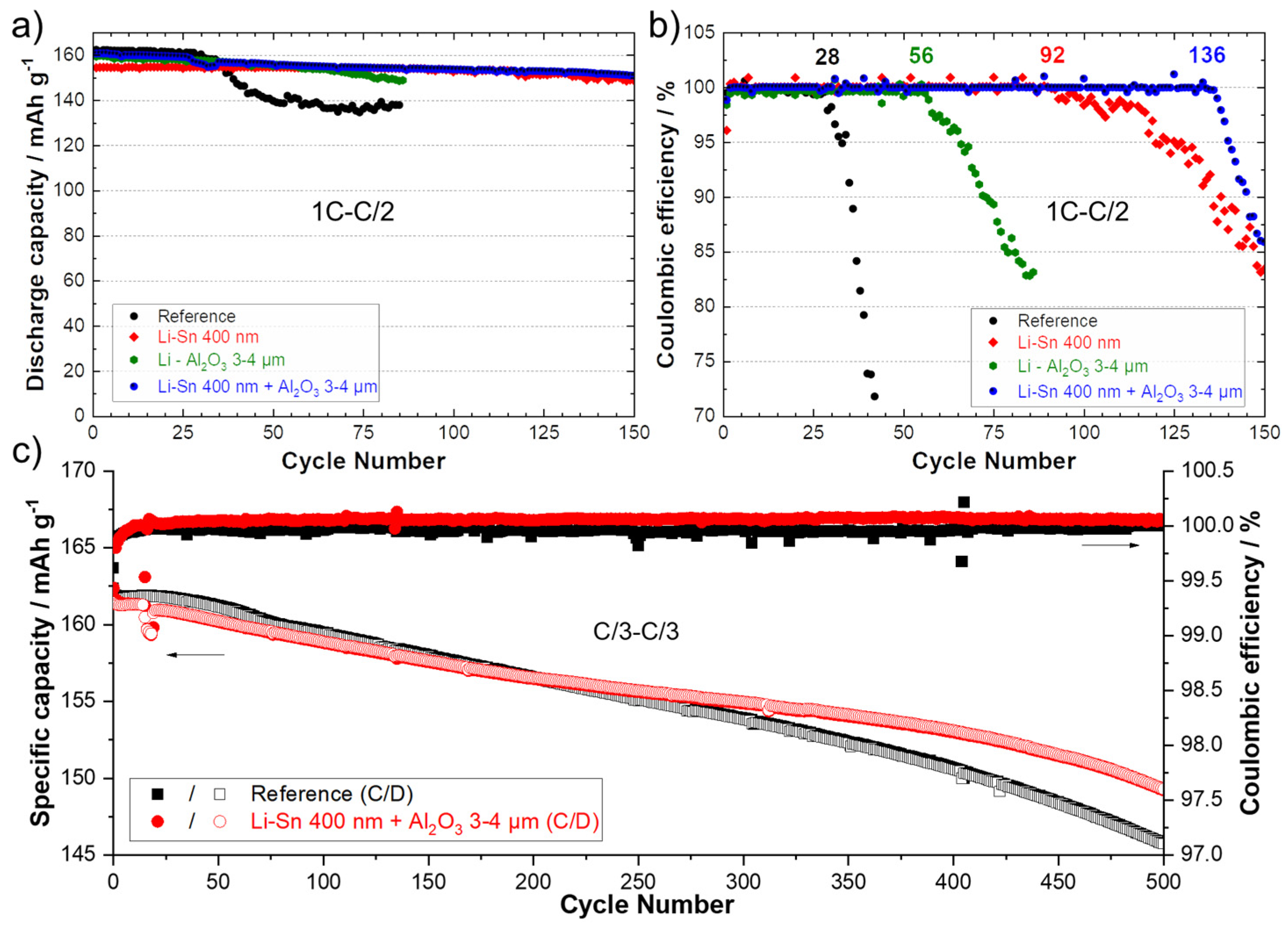
It was proposed to combine two kinds of protective layers on the Li surface to see if their effect could be cumulative. Even if 600 nm of sputtered Sn demonstrated good results, in reality, it represents a layer of about 2 to 2.3 µm. In an aim to reduce the cost of the process (less material deposited also means faster process) and the weight of the anode (to increase the specific energy of the system), a coating of only 400 nm was selected. Moreover, the deposition of a 3–4 µm polymer/ceramic layer by the conventional doctor blade casting method was proposed as the second technical layer to prevent the Li dendrites to progress through the SPE. Polymer/ceramic interlayers are largely reported today to have a significant role in increasing the performance of several types of batteries [3,4,36,37,38,39]. In a previous work, we demonstrated the double advantageous of thin polymer/ceramic interlayers. Firstly, it dramatically improves the contact between the SPE and the polymer-coated Li anode. Secondly, it slows down the progression of Li dendrites inside the polymer/ceramic layer and reduces the deformation of the Li anode/SPE interface [20]. The same composition was employed using Al2O3 ceramic with needle-like morphology and a PEO polymer. In the present study, a layer of 3–4 µm is deposited, but thinner and more homogeneous coatings could easily be obtained with a roll-to-roll slot-die coater. Figure S5a shows a photograph of the Li metal foil modified with two thin layers. Visually, the quality of the deposits is perfect, and this double modification could be easily integrated in a roll-to-roll process to protect the Li metal in a few seconds in an industrial production line. The SEM image and chemical mapping of the cross-section of this modified Li, in Figure S5b,c, shows perfect connections between the Li metal, the first layer of the Li–Sn alloy, and the second layer of the polymer/ceramic. However, the ceramic layer is not perfectly uniform (±1 µm of thickness), but it is most likely due to the limitations of the lab method of deposition that could be easily managed, for instance with a slot-die technique. To report the advantage of the double modification, LFP/SPE/Li batteries were assembled and cycled using Li anodes modified with a theoretical Li–Sn alloy layer of 400 nm, a polymer/ceramic layer of about 3–4 µm, and the combination of the two previous layers. Figure 7a,b present the discharge capacities (charge 1C–discharge C/2) and the corresponding Coulombic efficiencies for the reference cell and cells assembled with the various aforementioned surface modifications. The cell assembled with the Li metal modified by the polymer/ceramic layer performed twice the cycles the reference cell did. This result was expected and in accordance with those obtained for symmetrical cells in our previous study [20]. The cell with the Li anode covered with 400 nm of Sn was able to cycle for 92 cycles. It is less performant than the cell with the anode with a theoretical layer of 600 nm (See Figure 5), but it still represents an improvement of 330% in comparison to the reference. Note that the activation of capacity over dozens of cycles is not observed, probably because with 400 nm of Sn, as discussed above, the lithiation of the layer is more complete than for a thicker layer (e.g., 600 nm). Interestingly, the combination of the two surface modifications (first layer of LixSny alloy and second polymer/ceramic layer) permits to run the battery for 136 cycles at 1C–C/2 with a stable discharge capacity and Coulombic efficiency. The concept of double modification was also evaluated with long-term cyclability at a charge/discharge rate of C/3. The electrochemical performance for 500 cycles at C/3 for a reference cell (black) and a cell assembled with the modified Li anode (red) are presented in Figure 7c. Throughout the experiment, the cell with the modified anode showed a more stable Coulombic efficiency, revealing less side reactions at the anode surface. After 500 cycles (~4 months of cycling), the reference and the modified cells still delivered 146 and 150 mAh·g−1, which represents a capacity retention of 90.1 and 92.6%, respectively.
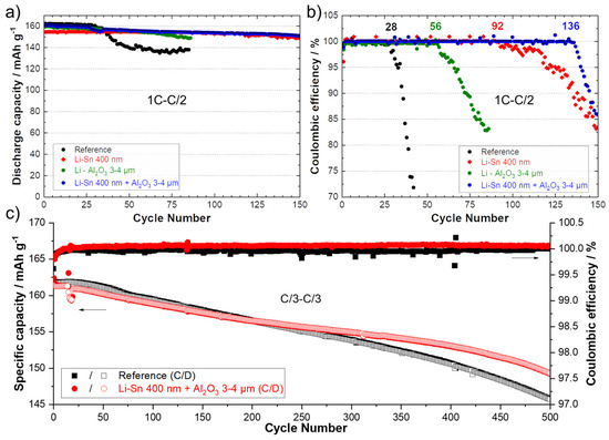
Figure 7.
(a) Discharge capacities (charge 1C–discharge C/2) and (b) Coulombic efficiencies for reference cells (black) and for cells using an anode with a theoretical Li–Sn alloy layer of 400 nm (red), an anode with a polymer/ceramic layer of about 3–4 µm (green) and a Li anode with the combination of the two previous layers (blue). (c) Specific capacities (charge C/3–discharge C/3) and Coulombic efficiencies for the reference cell (black) and for a cell using an anode with a theoretical Li–Sn alloy layer of 400 nm and a polymer/ceramic overcoating of about 3–4 µm (red).
3.4. Effect of Plasma Cleaning of Sn Surface
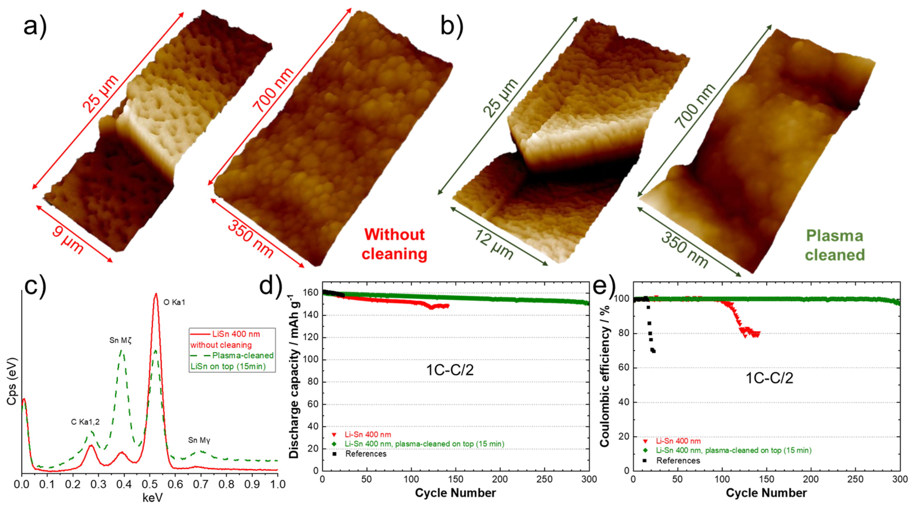
In our previous work, we demonstrated that the electrochemical performance of LiZn-protected anodes was strongly dependent on the parameters used for the deposition, such as cathodic current, target-substrate distance, or tilt angle [17], as they affect the surface topography. In the present work, it was proposed to investigate the effect of a post-cleaning with plasma in the aim of flattening and homogenizing the surface, as well as removing impurities that could be present. This additional treatment is interesting since it could be easily integrated into a roll-to-roll PVD system as an option. The surface of a Li anode modified with a theoretical Sn layer of 400 nm was observed with an AFM before (Figure 8a) and after a plasma cleaning of the surface for 15 min (Figure 8b). Before cleaning, the 3D atomic force microscope image at low magnification (left side, Figure 8a) shows the presence of holes with a diameter in the range of 2–4 µm. A closer look (right side, Figure 8a) reveals the presence of spherical particles with an average diameter of 50 nm. After cleaning with plasma, the surface appeared melted, the holes diminished in diameter (1–2 µm) and the grains were more uniform, as seen in Figure 8b (left side). A higher magnification of the surface (Figure 8b, right side) shows that the initial spherical clusters of few nanometers have melted together providing a less rough surface. Figure 8c shows the energy dispersive X-ray spectra for surface of the Li foil before (―) and after a post-cleaning of the surface (- - -). An intense peak of oxygen is obtained for the sample not cleaned due to the oxidation of the surface. This large peak “eclipses” those of Sn metal, which confirms a relative high contamination of the surface with air. After applying the post-cleaning with plasma, the intensity of Sn peaks considerably increased, and the quantity of oxygen clearly diminished. These observations confirm the utility of plasma to provide a cleaner and smoother surface, which are two requirements for achieving good cycling performance. This was well confirmed during cycling tests at 1C–C/2. The discharge capacities and Coulombic efficiencies for a reference cell and cells assembled with Li anodes modified with 400 nm of Sn before and after cleaning are presented in Figure 8d,e. The results show that the cell assembled with the untreated Sn-protected Li anode cycled for almost 100 cycles (similar to the first test in Figure 7a,b). As expected, using the plasma-cleaned Li anode, the cell was able to cycle correctly for 300 cycles at 1C–C/2. This result is impressive for an all-solid-state lithium-metal battery, and it represents an improvement of 1000% in comparison to the reference cell tested under the same conditions (from cell assembling to testing).
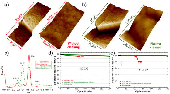
Figure 8.
Three-dimensional atomic force microscope images of the surface of a lithium foil after deposition of 400 nm Sn, (a) without and (b) with application of a 15 min plasma post-cleaning of the surface. Two magnifications are presented for both samples. (c) Energy dispersive X-ray spectra of the surface of a lithium foil after deposition of 400 nm of Sn, without plasma cleaning (―) and after a 15 min plasma post-cleaning of the surface (- - -). (d) Discharge capacities (charge 1C–discharge C/2) and (e) Coulombic efficiencies for the reference cell (black), for a cell using an anode with a theoretical 400 nm Li–Sn alloy layer without plasma cleaning (red) and for a cell using an anode with a theoretical 400 nm Li–Sn alloy layer that has been post-cleaned with plasma for 15 min (green).
4. Conclusions
The protection of the Li metal anode by the deposition of a thin LixSny alloy layer using the PVD technique is reported. The formation of a Li-rich alloy is confirmed by the volume expansion (up to 380%) of the deposited layer and by the disappearance of metallic Sn peaks in the X-ray diffractogram. However, the exact composition of the alloy layer is not clearly determined, and it is probably composed of several LixSny alloys. Moreover, nanoindentation measurements revealed that the layer has a much higher hardness than the bare Li anode, which can be useful to impede dendrite progression. An interesting feature was revealed with post-mortem scanning electron microscope observations of used LFP/SPE/Li pouch cells. It was found that the alloy layer remains intact even after fast cycling for hundreds of cycles. In addition, SnAl nanoparticles were formed at the Li/Sn interface by a very slow reaction between Sn and the Al additive initially present in the Li metal foil. Interestingly, no traces of Sn metal were found in the SPE or the Li bulk anode. Moreover, Al additives are still uniformly distributed into the Li bulk anode even after repetitive cycling at high C-rates, showing the electrodeposition of Li+ ions happens efficiently beneath the alloy layer. This artificial layer acts as a buffer layer for fast Li+ ion transfer. A concept of double modification by adding a thin ceramic/polymer layer deposited by a doctor blade on top of the LixSny layer was also reported to be efficient to reach long-term stability for 500 cycles at C/3. Finally, a post-treatment after Sn deposition consisting of a plasma cleaning of the LixSny alloy layer led to a strong improvement of the cycling performance at 1C (1000% in comparison to the Li metal anode, 300 charge/discharge cycles). The surface was found to be smoother and less oxidized after this treatment.
This artificial layer responds to the following requirements that are mandatory to achieve a good and cost-reliable protection of Li metal, as well as improved performance:
- -
- The process must be easily transposable at the industrial level, fast, clean, reproducible, cheap (Sn metal), and performed in a well-controlled environment.
- -
- Ultra-thin Li metal anode can also be modified with this technique.
- -
- The layer must be dense and thin to not impact the energy density of the electrochemical system.
- -
- The in-situ generation of a 3D Li-rich alloy favors the fast Li+ ion transfer at the SPE/Sn interface [40].
- -
- The chemical and electrochemical stabilities of the artificial layer permit to cycle the battery at high C-rates for several hundreds of cycles.
- -
- The higher electrochemical potential of the alloy layer in comparison to Li metal reduces the reactivity with the electrolyte [41].
- -
- Post-modifications can be applied on the alloy layer to respond to various applications (e.g., reduce the SPE thickness by deposing a thin ceramic-rich polymer layer, overcoating of a SPE, deposition of a non-electronic-conductive layer, etc.).
- -
- The electrodeposition of Li+ ions must occur uniformly underneath the artificial layer and on the Li metal side.
Our work proposes new designs and combinations of interlayers for the protection of Li metal anode. The electrochemical results reported in this work are quite good considering the all-solid-state battery configuration and the high cycling rate employed.
Supplementary Materials
The following supporting information can be downloaded at: https://www.mdpi.com/article/10.3390/batteries10070253/s1, Figure S1: Nanoindentation curves obtained on the surface of a piece of lithium metal that has been cleaned with plasma for 10 min and covered with a 50 nm layer of Sn. The curve in red represents the average calculated from 17 measurements shown in black; Figure S2: Nanoindentation curves obtained on the surface of the Li metal foil (black) and for pieces of lithium metal that have been coated with 400 nm of silver (red), bismuth (olive green), zinc (orange), tin (blue) and a 75%/25% tin/silver mixture (purple). The hardness value is shown in parentheses; Figure S3: Photographs of the Li metal before (left) and after (right) deposition of 600 nm of Sn; Figure S4: Galvanostatic charge profile (first charge) obtained at C/40 for an LFP/SPE/Li cell using a Li anode with a theoretical Li–Sn alloy layer of 600 nm; Figure S5: (a) Photograph of a Li foil with a theoretical 400 nm layer of Sn deposited by sputtering followed by a second layer of about 3–4 μm of a polymer/ceramic mixture deposited by coating. (b) Scanning electron microscope image of the Li foil with the first layer of Li–Sn alloy and the second layer of polymer/ceramic. (c) Chemical mapping of the lithium surface with the two layers for the following elements: Li, Sn, Al, C, O and F.
Author Contributions
Conceptualization, N.D.; methodology, N.D. and S.C.-M.; validation, N.D. and A.P.; formal analysis, N.D. and A.P.; investigation, N.D., A.P., S.C.-M., M.L., J.M., H.D., D.C., V.G. and W.Z.; resources, S.C.-M., M.L., J.M., H.D., D.C., V.G. and W.Z.; data curation, A.P.; writing—original draft preparation, N.D.; writing—review and editing, N.D.; visualization, N.D. and A.P.; supervision, N.D.; project administration, N.D. All authors have read and agreed to the published version of the manuscript.
Funding
This research received no external funding and was financially supported by Hydro-Québec.
Data Availability Statement
The original contributions presented in the study are included in the article, further inquiries can be directed to the corresponding author.
Acknowledgments
The laboratory experiments were conducted at the Center of Excellence in Transportation, Electrification, and Energy Storage (CETEES).
Conflicts of Interest
The authors declare that they have no known competing financial interests or personal relationships that could have appeared to influence the work reported in this paper.
References
- Tarascon, J.-M.; Armand, M. Issues and challenges facing rechargeable lithium batteries. Nature 2001, 414, 359–367. [Google Scholar] [CrossRef] [PubMed]
- Shen, Z.; Huang, J.; Xie, Y.; Wei, D.; Chen, J.; Shi, Z. Solid Electrolyte Interphase on Lithium Metal Anodes. ChemSusChem 2024, 17, e202301777. [Google Scholar] [CrossRef] [PubMed]
- Lee, D.J.; Lee, H.; Song, J.; Ryou, M.-H.; Lee, Y.M.; Kim, H.-T.; Park, J.-K. Composite protective layer for Li metal anode in high-performance lithium–oxygen batteries. Electrochem. Commun. 2014, 40, 45–48. [Google Scholar] [CrossRef]
- Peng, Z.; Wang, S.; Zhou, J.; Jin, Y.; Liu, Y.; Qin, Y.; Shen, C.; Han, W.; Wang, D. Volumetric variation confinement: Surface protective structure for high cyclic stability of lithium metal electrodes. J. Mater. Chem. A 2016, 4, 2427–2432. [Google Scholar] [CrossRef]
- Su, Z.; Zhang, J.; Jin, J.; Yang, S.; Li, G. Nanoscale surface modification of polymer nanofibers enables uniform lithium nucleation and deposition for stable lithium metal anodes. Chem. Eng. J. 2022, 430, 132865. [Google Scholar] [CrossRef]
- Liu, Y.; Lin, D.; Liang, Z.; Zhao, J.; Yan, K.; Cui, Y. Lithium-coated polymeric matrix as a minimum volume-change and dendrite-free lithium metal anode. Nat. Commun. 2016, 7, 10992. [Google Scholar] [CrossRef]
- Bai, M.; Xie, K.; Hong, B.; Yuan, K.; Li, Z.; Huang, Z.; Shen, C.; Lai, Y. An artificial Li3PO4 solid electrolyte interphase layer to achieve petal-shaped deposition of lithium. Solid State Ion. 2019, 333, 101–104. [Google Scholar] [CrossRef]
- Liang, J.; Li, X.; Zhao, Y.; Goncharova, L.V.; Wang, G.; Adair, K.R.; Wang, C.; Li, R.; Zhu, Y.; Qian, Y.; et al. In Situ Li3PS4 Solid-State Electrolyte Protection Layers for Superior Long-Life and High-Rate Lithium-Metal Anodes. Adv. Mater. 2018, 30, 1804684. [Google Scholar] [CrossRef] [PubMed]
- Lin, D.; Liu, Y.; Liang, Z.; Lee, H.-W.; Sun, J.; Wang, H.; Yan, K.; Xie, J.; Cui, Y. Layered reduced graphene oxide with nanoscale interlayer gaps as a stable host for lithium metal anodes. Nat. Nanotechnol. 2016, 11, 626–632. [Google Scholar] [CrossRef]
- Ryou, M.-H.; Lee, Y.M.; Lee, Y.; Winter, M.; Bieker, P. Mechanical Surface Modification of Lithium Metal: Towards Improved Li Metal Anode Performance by Directed Li Plating. Adv. Funct. Mater. 2015, 25, 834–841. [Google Scholar] [CrossRef]
- Kazyak, E.; Wood, K.N.; Dasgupta, N.P. Improved Cycle Life and Stability of Lithium Metal Anodes through Ultrathin Atomic Layer Deposition Surface Treatments. Chem. Mater. 2015, 27, 6457–6462. [Google Scholar] [CrossRef]
- Kozen, A.C.; Lin, C.-F.; Pearse, A.J.; Schroeder, M.A.; Han, X.; Hu, L.; Lee, S.-B.; Rubloff, G.W.; Noked, M. Next-Generation Lithium Metal Anode Engineering via Atomic Layer Deposition. ACS Nano 2015, 9, 5884–5892. [Google Scholar] [CrossRef] [PubMed]
- Chen, L.; Chen, K.-S.; Chen, X.; Ramirez, G.; Huang, Z.; Geise, N.R.; Steinrück, H.-G.; Fisher, B.L.; Shahbazian-Yassar, R.; Toney, M.F.; et al. Novel ALD Chemistry Enabled Low-Temperature Synthesis of Lithium Fluoride Coatings for Durable Lithium Anodes. ACS Appl. Mater. Interfaces 2018, 10, 26972–26981. [Google Scholar] [CrossRef] [PubMed]
- Alaboina, P.K.; Rodrigues, S.; Rottmayer, M.; Cho, S.-J. In Situ Dendrite Suppression Study of Nanolayer Encapsulated Li Metal Enabled by Zirconia Atomic Layer Deposition. ACS Appl. Mater. Interfaces 2018, 10, 32801–32808. [Google Scholar] [CrossRef] [PubMed]
- Bela, M.M.; Schmidt, C.; Neuhaus, K.; Hering, T.; Stan, M.C.; Winter, M.; Börner, M. Tunable LiZn-Intermetallic Coating Thickness on Lithium Metal and Its Effect on Morphology and Performance in Lithium Metal Batteries. Adv. Mater. Interfaces 2024, 11, 2300836. [Google Scholar] [CrossRef]
- Stan, M.C.; Becking, J.; Kolesnikov, A.; Wankmiller, B.; Frerichs, J.E.; Hansen, M.R.; Bieker, P.; Kolek, M.; Winter, M. Sputter coating of lithium metal electrodes with lithiophilic metals for homogeneous and reversible lithium electrodeposition and electrodissolution. Mater. Today 2020, 39, 137–145. [Google Scholar] [CrossRef]
- Delaporte, N.; Perea, A.; Collin-Martin, S.; Léonard, M.; Matton, J.; Gariepy, V.; Demers, H.; Clément, D.; Rivard, E.; Vijh, A. High Performance Lithium Metal Anode with a Nanolayer of LiZn Alloy for All-Solid-State Batteries, Batter. Supercaps 2022, 5, e202200245. [Google Scholar] [CrossRef]
- Park, S.-H.; Lee, S.-M.; Ko, E.-H.; Kim, T.-H.; Nah, Y.-C.; Lee, S.-J.; Lee, J.H.; Kim, H.-K. Roll-to-Roll sputtered ITO/Cu/ITO multilayer electrode for flexible, transparent thin film heaters and electrochromic applications. Sci. Rep. 2016, 6, 33868. [Google Scholar] [CrossRef]
- Tao, X.; Stuart, B.W.; Assender, H.E. Roll-to-roll manufacture of flexible thin-film thermoelectric generators using flexography with vacuum vapour deposition. Surf. Coat. Technol. 2022, 447, 128826. [Google Scholar] [CrossRef]
- Delaporte, N.; Lajoie, G.; Darwiche, A.; Vigeant, M.-J.; Collin-Martin, S.; Clément, D. Stabilization of lithium anode with ceramic-rich interlayer for all solid-state batteries. RSC Adv. 2022, 12, 15493–15507. [Google Scholar] [CrossRef]
- Fujiwara, S.; Tamura, Y.; Maki, H.; Azuma, N.; Takeuchi, Y. Development of New High-Purity Alumina. Available online: https://www.sumitomo-chem.co.jp/english/rd/report/files/docs/20070102_fth.pdf (accessed on 14 July 2024).
- Hovington, P.; Timoshevskii, V.; Burgess, S.; Demers, H.; Statham, P.; Gauvin, R.; Zaghib, K. Can We Detect Li K X-ray in Lithium Compounds Using Energy Dispersive Spectroscopy? Scanning 2016, 38, 571–578. [Google Scholar] [CrossRef] [PubMed]
- Tamura, N.; Ohshita, R.; Fujimoto, M.; Kamino, M.; Fujitani, S. Advanced Structures in Electrodeposited Tin Base Negative Electrodes for Lithium Secondary Batteries. J. Electrochem. Soc. 2003, 150, A679. [Google Scholar] [CrossRef]
- Wang, J.; Raistrick, I.D.; Huggins, R.A. Behavior of Some Binary Lithium Alloys as Negative Electrodes in Organic Solvent-Based Electrolytes. J. Electrochem. Soc. 1986, 133, 457–460. [Google Scholar] [CrossRef]
- Serikkazyyeva, A.; Mashekova, A.; Uzakbaiuly, B.; Bakenov, Z.; Mukanova, A. Novel Li/LixSny thin film designed as an anode for lithium-ion microbatteries. J. Alloys Compd. 2023, 965, 171381. [Google Scholar] [CrossRef]
- Li, M.; Zhou, D.; Wang, C.; Weng, W.; Jiang, M.; Liu, G.; Yao, X.; He, H. In Situ Formed Li–Ag Alloy Interface Enables Li10GeP2S12-Based All-Solid-State Lithium Batteries. ACS Appl. Mater. Interfaces 2021, 13, 50076–50082. [Google Scholar] [CrossRef] [PubMed]
- Zhang, W.-J. Lithium insertion/extraction mechanism in alloy anodes for lithium-ion batteries. J. Power Sources 2011, 196, 877–885. [Google Scholar] [CrossRef]
- Joachin, H.; Kaun, T.D.; Zaghib, K.; Prakash, J. Electrochemical and Thermal Studies of Carbon-Coated LiFePO4 Cathode. J. Electrochem. Soc. 2009, 156, A401–A406. [Google Scholar] [CrossRef]
- Sakuma, M.; Suzuki, K.; Hirayama, M.; Kanno, R. Reactions at the electrode/electrolyte interface of all-solid-state lithium batteries incorporating Li–M (M = Sn, Si) alloy electrodes and sulfide-based solid electrolytes. Solid State Ion. 2016, 285, 101–105. [Google Scholar] [CrossRef]
- Li, X.; Liang, J.; Yang, X.; Adair, K.R.; Wang, C.; Zhao, F.; Sun, X. Progress and perspectives on halide lithium conductors for all-solid-state lithium batteries. Energy Environ. Sci. 2020, 13, 1429–1461. [Google Scholar] [CrossRef]
- Riegger, L.M.; Schlem, R.; Sann, J.; Zeier, W.G.; Janek, J. Lithium-Metal Anode Instability of the Superionic Halide Solid Electrolytes and the Implications for Solid-State Batteries. Angew. Chem. Int. Ed. 2021, 60, 6718–6723. [Google Scholar] [CrossRef]
- Zhao, F.; Sun, Q.; Yu, C.; Zhang, S.; Adair, K.; Wang, S.; Liu, Y.; Zhao, Y.; Liang, J.; Wang, C.; et al. Ultrastable Anode Interface Achieved by Fluorinating Electrolytes for All-Solid-State Li Metal Batteries. ACS Energy Lett. 2020, 5, 1035–1043. [Google Scholar] [CrossRef]
- Zhang, H.; Song, X.; Pu, Y.; Ding, M.; Zhang, W.; Cao, P. In-situ polymerisation of fluorene to achieve theoretical capacity in LiFePO4 cells. Electrochim. Acta 2024, 483, 143999. [Google Scholar] [CrossRef]
- Homann, G.; Stolz, L.; Neuhaus, K.; Winter, M.; Kasnatscheew, J. Effective Optimization of High Voltage Solid-State Lithium Batteries by Using Poly(ethylene oxide)-Based Polymer Electrolyte with Semi-Interpenetrating Network. Adv. Funct. Mater. 2020, 30, 2006289. [Google Scholar] [CrossRef]
- Homann, G.; Stolz, L.; Nair, J.; Laskovic, I.C.; Winter, M.; Kasnatscheew, J. Poly(Ethylene Oxide)-based Electrolyte for Solid-State-Lithium-Batteries with High Voltage Positive Electrodes: Evaluating the Role of Electrolyte Oxidation in Rapid Cell Failure. Sci. Rep. 2020, 10, 4390. [Google Scholar] [CrossRef] [PubMed]
- Liu, Y.; Lin, D.; Yuen, P.Y.; Liu, K.; Xie, J.; Dauskardt, R.H.; Cui, Y. An Artificial Solid Electrolyte Interphase with High Li-Ion Conductivity, Mechanical Strength, and Flexibility for Stable Lithium Metal Anodes. Adv. Mater. 2017, 29, 1605531. [Google Scholar] [CrossRef]
- Jing, H.-K.; Kong, L.-L.; Liu, S.; Li, G.-R.; Gao, X.-P. Protected lithium anode with porous Al2O3 layer for lithium–sulfur battery. J. Mater. Chem. A 2015, 3, 12213–12219. [Google Scholar] [CrossRef]
- Hu, Z.; Liu, F.; Gao, J.; Zhou, W.; Huo, H.; Zhou, J.; Li, L. Dendrite-Free Lithium Plating Induced by In Situ Transferring Protection Layer from Separator. Adv. Funct. Mater. 2020, 30, 1907020. [Google Scholar] [CrossRef]
- Yang, C.; Liu, B.; Jiang, F.; Zhang, Y.; Xie, H.; Hitz, E.; Hu, L. Garnet/polymer hybrid ion-conducting protective layer for stable lithium metal anode. Nano Res. 2017, 10, 4256–4265. [Google Scholar] [CrossRef]
- Liang, X.; Pang, Q.; Kochetkov, I.R.; Sempere, M.S.; Huang, H.; Sun, X.; Nazar, L.F. A facile surface chemistry route to a stabilized lithium metal anode. Nat. Energy 2017, 2, 17119. [Google Scholar] [CrossRef]
- Zhu, Y.; He, X.; Mo, Y. Origin of Outstanding Stability in the Lithium Solid Electrolyte Materials: Insights from Thermodynamic Analyses Based on First-Principles Calculations. ACS Appl. Mater. Interfaces 2015, 7, 23685–23693. [Google Scholar] [CrossRef]


Disclaimer/Publisher’s Note: The statements, opinions and data contained in all publications are solely those of the individual author(s) and contributor(s) and not of MDPI and/or the editor(s). MDPI and/or the editor(s) disclaim responsibility for any injury to people or property resulting from any ideas, methods, instructions or products referred to in the content. |
© 2024 by the authors. Licensee MDPI, Basel, Switzerland. This article is an open access article distributed under the terms and conditions of the Creative Commons Attribution (CC BY) license (https://creativecommons.org/licenses/by/4.0/).