Article

Passivity-Based Control for Transient Power Sharing and State of Charge Restoration in a Semi-Active Supercapacitor-Battery System

by
Fabian Fracica-Rodriguez
1,
Manuel Acevedo-Iles
1,
David Romero-Quete
1,
Wilmar Martinez
2 and
Camilo A. Cortes
1,*
1
Department of Electrical and Electronic Engineering, Universidad Nacional de Colombia, Bogotá 111321, Colombia
2
Department of Electrical Engineering (ESAT), KU Leuven—EnergyVille, Thor Park 8310, 3600 Genk, Belgium
*
Author to whom correspondence should be addressed.
Batteries 2024, 10(9), 322; https://doi.org/10.3390/batteries10090322
Submission received: 2 August 2024 / Revised: 9 September 2024 / Accepted: 11 September 2024 / Published: 12 September 2024
(This article belongs to the Section Battery Modelling, Simulation, Management and Application)

Abstract

:
This paper presents a passivity-based control (PBC) approach integrated with filtering for a supercapacitor (SC) in a semi-active hybrid energy storage system. The PBC is designed as a current controller using the reference provided by the filter to regulate the system’s load current. Additionally, an external loop is employed to regulate the SC voltage to a desired value. In this external loop, a low-pass filter is included to decouple voltage and current control during instantaneous changes in load. A detailed, step-by-step description of both the PBC and the SC voltage control strategy is provided, illustrating how voltage regulation is effectively decoupled from current control to ensure optimal operation during load transients. The effectiveness of the proposed control strategy is validated through simulations and Power Hardware-in-the-Loop testing under variable current loads. This comprehensive evaluation method enables testing of control strategies in scenarios closely resembling real-world applications.

Graphical Abstract

1. Introduction

Power fluctuations due to the use of unconventional renewable energies and the uncertainty associated with demand are significant challenges in the operation of electric microgrids. To address these issues, various types of energy storage are employed, primarily using batteries, as they offer a range of services to power systems, such as ancillary services, end-user services, and integration with renewable generation, thereby improving the overall performance of the system [1]. Simultaneously, it has been demonstrated that the use of Hybrid Energy Storage Systems (HESS) enhances system efficiency by combining the individual benefits of different storage types [2].
The integration of batteries and supercapacitors as hybrid storage systems presents a compelling approach, leveraging their complementary attributes. Batteries offer high energy density but typically suffer from low power density. In contrast, supercapacitors excel in rapid charge and discharge cycles, although with lower energy density. This inherent duality allows for a synergistic combination that addresses both high power demands and energy storage requirements [3]. Furthermore, supercapacitors (SC) have an extremely long lifespan due to their structural aspects, which, coupled with their rapid response, enables them to compensate for short-duration fluctuations occurring on the DC bus. By doing so, they alleviate the burden on batteries, effectively prolonging their operational life and reducing maintenance costs. Consequently, this hybrid approach proves particularly well suited for applications prioritizing high power capabilities and swift charging over long-term energy storage capacity [3].
In the context of Hybrid Energy Storage Systems (HESS), three common connection topologies exist: passive, active, and semi-active [4]. In a passive topology, the storage systems are directly connected to the load and the DC bus without active control. This configuration requires the voltage of the storage elements to match that of the DC bus, often resulting in inefficient energy management [5]. The active topology offers the highest level of flexibility and efficiency by actively controlling both storage systems using bidirectional DC/DC converters. This allows for dynamic energy distribution and maintains the DC bus voltage within a safe range [4,6]. However, the complexity and costs associated with this configuration can be prohibitive in certain applications [7].
In contrast, the semi-active topology enhances energy management by connecting one of the storage systems through a controlled DC/DC converter, while the other remains directly connected to the DC bus [2]. Despite encountering limitations such as variations in the DC bus when connecting high-power density devices and the lack of complete control over the HESS by only managing one storage system [8,9], this configuration offers enhanced control flexibility compared to the passive topology. Additionally, it involves lower implementation costs and complexity than the active topology. Therefore, the semi-active topology is often regarded as an attractive option, striking a balance between efficiency and complexity. This enables efficient energy management while maintaining a reasonable level of complexity and cost compared to passive and active topologies [6,7,10].
Multiple studies on semi-active topology have been proposed in the literature. Regarding control techniques, filter-based methods are commonly utilized, where filters are employed to segregate high-frequency (HF) and low-frequency (LF) components. This allows for the power sharing of these components with the corresponding storage systems [4]. Studies such as [11,12,13,14] demonstrate the effectiveness of frequency division in generating current references for storage systems, alongside the implementation of PI control for the DC/DC converter. Furthermore, peak current control has been implemented in semi-active HESS systems [15,16] to broaden the frequency bandwidth of the current control loop. However, this approach may be susceptible to noise, potentially leading to system instabilities.
In [17], a controller based on a combination of filtering and fuzzy control is proposed to reduce stress on the battery while ensuring that the SC voltage varies within a desired range. An interconnection and damping assignment passivity-based control is presented in [10] for both semi-active and active topology systems, aiming to ensure stability by formulating the system in terms of energy. It is noted that the capacitor semi-active topology reduces stress on the battery similarly to the active topology. However, it sacrifices DC bus regulation, which remains fixed at the battery voltage. In [18,19], sliding mode control combined with filtering is utilized to formulate a controller that addresses system nonlinearities and ensures stability across all operating points. In [20,21], approaches for optimizing hybrid storage in electric vehicles are investigated. In [20], the focus is on simulating hybrid topologies and model predictive control (MPC) to introduce a macroscopic energetic representation that enables the development of an effective management system. In [21], an energy management strategy (EMS) based on Pontryagin’s minimum principle (PMP) is developed to reduce energy consumption and slow down battery degradation. Nonetheless, many of these papers solely validate their proposed strategies through simulations, which does not allow for testing their performance in environments closely resembling reality. Furthermore, there is a notable absence of studies addressing the decoupling between voltage control for the SC and current control, which could potentially lead to system instabilities, especially under sudden changes in a constant power load.
In light of the limitations of existing control techniques for semi-active HESS configurations, this paper introduces a passivity-based control strategy combined with filtering for a capacitor-based semi-active HESS topology. Additionally, a strategy for SC voltage control is presented to decouple voltage regulation from current control, ensuring smooth operation during load transients. The enhanced characteristics of the proposed control algorithm are validated through simulations and Power Hardware-in-the-Loop (PHIL) testing, thereby verifying its performance under real operating conditions. This approach enables testing in environments closely resembling practical applications, ensuring the effectiveness of the control strategies across different scenarios.
The remainder of the paper is structured as follows: Section 2 delves into the foundational theory underlying the strategy. Section 3 outlines the design of the proposed control strategy. Section 4 discusses the setup details for real-time simulation and PHIL validation. Section 5 presents the results from both simulation and PHIL validation. Lastly, Section 6 presents the conclusions drawn from our study.

2. Background

This section is divided into four subsections. The first subsection presents the filter-based technique to obtain the dynamic current reference for converter control. The second subsection discusses the SoC Recovery for SC, aimed at maintaining V S C at a desired value to ensure its operation. The third subsection explains the design of the passivity-based control.

2.1. Filter-Based Technique

The filter-based control technique is used to derive the reference assigned to each energy storage system by appropriately distributing the load components. To implement this technique, it is necessary to measure the system’s load current ( i o ). This current can be directly measured in the equivalent load seen from the HESS, or it can be obtained from the current delivered by each storage system, as illustrated in Figure 1.
Once the load current is obtained, a filter is used to separate the high- and low-frequency components of the load. This allows separating the load components into dynamic ( i d y n m ) and average ( i a v g ) components, which are assigned to the storage devices depending on their physical properties [13]. For a HESS composed of a battery and SC, the average load component is assigned to the battery ( i B a t ), while the dynamic component is assigned to the SC ( i o S C c o n v ).
i o = i a v g + i d y n m = i B a t + i o S C c o n v
In a semi-active topology where the SC is controlled, the objective of the control strategy is for the SC to assume the high-frequency components, thus acting as an active filter for the battery. Consequently, the output current of the converter represents the equivalent of a high-pass filter (HPF) in the load current.
i d y n m = i o S C c o n v = H P F ( i o ) = H P F ( s ) · i o
The battery equivalently provides the low-frequency components of the load. As demonstrated in the following equations
i o = i B a t + H P F ( s ) · i o
i B a t = i o H P F ( s ) · i o = ( 1 H P F ( s ) ) · i o = L P F ( s ) · i o

2.2. SoC Recovery for SC

To control the State of Charge (SOC) of the SC, it is necessary to describe its approximate behavior. The dynamic behavior of the SC current is given by
d V S C d t = 1 C S C · i S C
where V S C is the SC voltage, i L S C is the SC current, and C S C is the SC capacitance. From this, the instantaneous voltage for the SC is derived
V S C = V S C i n i t 1 C S C · i S C d t
As shown in the expression (6), the SC voltage can be used as a direct reference for the SoC. Therefore, this value is employed to control the SoC to a specified set point [22].
The control of V S C represents an outer control loop compared to the inner current control loop designed to handle system transients. In the control design, the inner loop is expected to be much faster than the outer loop, allowing the assumption that the current control is instantaneous for the V S C control. Thus, the voltage control only perceives the equivalent model of the capacitor, which can be viewed as a pure integrator. As a result, the voltage control can achieve zero steady-state error using only proportional control [14].

2.3. Passivity-Based Control Design

This subsection provides a general explanation of the theory behind passivity-based control design. Passivity-based control enables the regulation of nonlinear system behavior through a desired storage function that modifies the closed-loop system dynamics, leveraging passivity properties to ensure system stability [23]. Based on the dynamic model of the system, a representation as a port-Hamiltonian system is performed to obtain the model in terms of energy and to formulate the passivity-based control. The general expression of a port-Hamiltonian system is [24]
D x ˙ J ( u ) x + R x = E
where D is the inertia matrix, and J (u) is the interconnection matrix, which satisfies the property that x J x = 0 to ensure that its internal energy be zero, associated with the condition that J ( u ) be antisymmetric, i.e., J ( u ) = J ( u ) . R is the damping matrix, which is semi-positive definite. E is the vector of external sources. x is the state vector of the system, which includes variables such as voltages and currents in the capacitors and inductors, respectively. u is the input vector of the system, which in this case, represents the control signal.
The objective of the passivity-based control (PBC) methodology is to make the closed-loop system passive based on a desired storage function ( H d ) [24], defined as follows:
H d = 1 2 x ¯ T D x ¯
where x ¯ = x x * , and x ¯ represents the error vector of x relative to the desired value x * . Considering the system is underactuated due to the Boost converter topology, the desired values of x cannot be freely assigned.
A damping matrix is added to dissipate the error in steady state [25], modifying the damping matrix R as follows:
R d = R + R 1
where R 1 is a positive-definite damping injection matrix for the system. The value of R 1 can be designed within the bounds of damping injection coefficients proposed in [26].
Thus, rewriting the desired error dynamics from Equation (7) with the modified damping matrix
D x ¯ ˙ J ( u ) x ¯ + R d x ¯ = Ψ
where Ψ is a disturbance term defined as follows:
Ψ = E ( D x ˙ * J ( u ) x * + R x * ) + R 1 x ¯
It is crucial to ensure system stability. This is achieved by selecting a desired storage function acting as a Lyapunov candidate function, satisfying H ( 0 ) = 0 , H ( x ) > 0 when x 0 , and ensuring system stability requires H ˙ ( x ) < 0 . Calculating the derivative of the storage function
H ˙ d ( x ¯ ) = x ¯ D x ¯ ˙ = x ¯ ( J ( u ) R d ) x ¯ + x ¯ Ψ
As mentioned earlier, J ( u ) satisfies x ¯ T J ( u ) x ¯ = 0, and since the objective of the control input u is to drive the error dynamics to zero, the disturbance term Ψ is assumed to be zero.
H ˙ d ( x ¯ ) = x R d x ¯ α β H d
where α = m i n { R d 11 , R d 22 , , R d n n } and β = m a x { D 11 , D 22 , , D n n } , which correspond to the minimum of the diagonal of the matrix R d and the maximum of the diagonal of the matrix D , respectively. Proving that the system dynamics are globally exponentially stable in the sense of Lyapunov [24].
By equating the disturbance term to zero
D x ˙ * J ( u ) x * + R x * R 1 x ¯ = E
From the above expression and the system description matrices, the expression for the control u can be derived, along with expressions for the uncontrolled states of the system, defined using auxiliary expressions based on desired values that these variables may follow. It is important to note that, for the proposed control strategy, it is necessary to have approximate values for the components that describe the system. This enables the control signal u to effectively cancel out disturbances.

3. Proposed Control Strategy

Based on the results presented in [27], which compares two semi-active topology configurations, it is shown that the configuration where the supercapacitor (SC) is controlled is more efficient and stable than the configuration where the battery is controlled. This makes the SC-controlled configuration attractive for applications with sudden load changes.
Considering the aforementioned findings, Figure 2 presents the model used for the semi-active SC-controlled HESS topology along with the net current load. This model includes an SC represented as a capacitance connected through a bidirectional converter to the DC bus. Additionally, there is a current load and an equivalent battery model connected through an inductor. The proposed model incorporates an inductor on the battery side to increase the time constant for current changes, compensating for limitations in the converter’s switching frequency, and allowing the SC to handle initial transients during load current changes effectively.
For the proposed control system, the scheme shown in Figure 3 was employed. This control system comprises an outer loop that regulates the SC voltage to the desired reference level, along with a low-pass filter and proportional control to ensure decoupling of the voltage control and zero steady-state error. Subsequently, a current control is applied in the inner loop, where the reference is obtained from the high-frequency component of the load and SC voltage control, adjusting it to provide the reference value to the converter’s input inductor. Finally, the passivity-based current control is used to obtain the control signal “u” that is applied to the converter.

3.1. Used Filter-Based Technique

As illustrated in Section 2.1, a high-pass filter (HPF) is used to obtain the current that the SC must provide at the converter’s output. For the converter, the controlled variable is the input inductor current, so it is necessary to obtain the converter’s input current in terms of the output current. To achieve this, the equivalent power balance in the converter is used, disregarding any losses.
P i n = P o u t
V S C · i L S C = V D C · i o S C
where P i n and P o u t are the input and output powers of the converter, respectively. V S C is the voltage of the SC, i L S C is the current of the converter’s input inductor, which is equivalent to the SC current. V D C represents the voltage at the equivalent connection point where the load is connected, and i o S C is the output current of the converter. Considering that the reference current at the converter output ( i o S C * ) is equal to the high-frequency component of the load ( i o H P F * ), the current reference for the inductor ( i L S C * ) is
i o S C * = i o H P F * = H P F ( i o )
i L S C * = V D C V S C i o H P F *
This allows obtaining the reference current that the inductor must follow so that the SC delivers the necessary current to operate during load transients and enables the battery to only deliver the current in steady state (low-frequency component).

3.2. Proposed SoC Restoration Strategy

We propose the implementation of a control strategy for the State of Charge (SoC) of the SC to maintain its operating voltage within a specific range, allowing the SC to respond to system transients. As depicted in [28], an SC exhibits instantaneous voltage variations in response to sudden current changes. These fluctuations in V S C can influence the current control dynamics by modifying the reference corresponding to the high-frequency component of the load. A low-pass filter (LPF) is added to the error between the voltage reference and the measured SC voltage ( V S C ) to limit the rate of change seen in V S C . This prevents the instantaneous dynamic current required by the load from being affected and decouples the external voltage control from the internal current control.
To validate the aforementioned approach, a small-signal analysis is performed based on the variations observed in the V S C . Using the expression given in (6), the following expression for the variation of V S C ( V ^ S C ) is obtained
V ^ S C = i ^ S C C S C · s = i ^ o S C D · C S C · s
where i ^ S C and i ^ o S C are the variations in the input and output currents of the converter, respectively, D is the steady-state duty cycle, and C S C is the capacitance of the SC. To compensate for these variations, a proportional control along with a LPF is employed to obtain the current necessary to restore the SoC
i S o C * = L P F ( i ^ o S C D · C S C · s ) · K p
Finally, it is found that the variations in the converter output current are given by the combination of the dynamic load current reference and the current needed to restore the SoC of the SC
i ^ o S C = i o H P F * + i S o C *
i ^ o S C = H P F ( i ^ o ) L P F ( i ^ o S C D · C S C · s ) · K p
In this case, first-order transfer functions of the low-pass (LP) and high-pass (HP) filters are used, where T 1 is the time constant of the HP filter and T 2 is the time constant of the LP filter.
i ^ o S C = T 1 · s 1 + T 1 · s ( i ^ o ) 1 1 + T 2 · s · i ^ o S C D · C S C · s · K p
Solving for the converter output current, the following expression is obtained in terms of the load current, where the transfer function G ( s ) represents the behavior of the converter output current:
i ^ o S C = G ( s ) i ^ o
i ^ o 1 = T 1 · s 1 + T 1 · s 1 + K p 1 + T 2 · s · 1 D · C S C · s i ^ o
To perform an approximate design of the system’s settling time along with the proposed SoC control, it is possible to assume that the HPF operates faster compared to the LPF, thus taking a value of 1 for the design. In this way, an auxiliary function G a u x is used to obtain the values of T 2 for the LPF and K p to achieve the desired behavior.
G a u x = 1 1 + K p 1 + T 2 · s · 1 D · C S C · s = s 2 + 1 T 2 s s 2 + 1 T 2 s + K p D · C S C · T 2
A desired polynomial P ( s ) is then chosen that has the desired settling time, which is taken as a reference to find the values of the denominator of G a u x
P ( s ) = s 2 + b s + c = s 2 + 1 T 2 s + K p D · C s c · T 2
In this way, the values of T 2 and K p that allow achieving the desired settling time for the system are obtained
T 2 = 1 b ; K p = D · C s c · T 2 · c ;
To validate the performance of the strategy, the approach with SoC control and without SoC control were compared using a step response. For the strategy without SoC control of the SC, a high-pass filter with a settling time of 5s was proposed, resulting in T 1 = 1 . In contrast, for the strategy with SoC control of the SC, a polynomial with a settling time of 15 s was proposed, yielding T 2 = 1.2 and K p = 8.645 . The results obtained from these values are shown in Figure 4. As observed in the results, the strategy without SoC restoration simply ensures that the SC handles the load transient, allowing the battery to reach the steady state smoothly. On the other hand, the strategy with SoC behaves similarly to the former in the initial phase. However, as time progresses, the reference current of the SC does not stabilize directly at zero but instead draws current for a certain period. This means that the SC charges smoothly after supplying the transient current until it reaches the desired voltage reference and stabilizes its current at zero in steady state. This demonstrates the effectiveness of the proposed strategy, allowing the voltage and current controls to decouple correctly. Consequently, the transient current provided by the SC meets the design requirement while smoothly returning to its desired SoC.
The resulting reference current is assumed at the converter output, ensuring that the control considers the current demanded from the battery for SoC management, thereby guaranteeing system stability. Consequently, to obtain the inductor’s reference current that ensures the SC can respond to transient events while maintaining the SoC within a desired range, the following expression is derived:
i L S C * = V D C V S C ( i o H P F * + I S o C * )

3.3. Current Passivity-Based Control Design

Once the current reference is obtained, a current control is designed using the PBC methodology. The equations describing the dynamic model of the system are presented in Equations (30)–(32). For the control design, the SC is assumed to be an ideal voltage source, considering that an external control loop is proposed for the SC voltage.
L S C d d t i L S C = V S C ( 1 u ) · V D C
C o u t d d t V D C = ( 1 u ) · i L S C i L B a t i o
L B a t d d t i L B a t = V D C R B a t · i L B a t V B a t
where L S C and L B a t represent the inductances of the SC and battery converters, C o u t is the output capacitor of the converter, V S C , V B a t , and V D C represent the voltages of the SC, battery, and DC bus, respectively, i L S C and i L B a t are the inductor currents, R B a t is the equivalent model of the internal resistance of the battery, i o is the net load current applied to the HESS, and u is the average control signal applied to the system.
The matrices that represent the dynamic system as a port-Hamiltonian system are
D = L S C 0 0 0 C o u t 0 0 0 L B a t ; J = 0 ( 1 u ) 0 ( 1 u ) 0 1 0 1 0 ; R = 0 0 0 0 0 0 0 0 R B a t ;
x = i L S C V D C i L B a t ; E = V S C i o V b a t ;
In this case, a current control is proposed based on the inductor current of the converter i L s c , making this the controlled variable. Since the system is underactuated, the other system states are defined from the auxiliary control expressions. According to [26], the damping coefficient value can be determined as follows:
k L s c · f · 2 π
Therefore, the damping injection matrix is
R 1 = k 0 0 0 0 0 0 0 0
Following the PBC design described in Section 2.3, the disturbance Ψ is set to zero, as shown in Equation (14). Solving along with the system matrices, the following expressions are obtained
L S C d d t i L S C * + ( 1 u ) · V D C * k ( i L S C i L S C * ) = V S C
C o u t d d t V D C * ( 1 u ) · i L S C * + i L b a t * = i o
L B a t d d t i L B a t * V D C * + R B a t · i L b a t * = V B a t
Considering that the reference for the current i L s c is known, the control signal u applied to the system is
u = 1 V S C L S C d d t i L S C * + k ( i L S C i L S C * ) V D C *
The value of V D C * can be determined using Equations (34) and (35), or alternatively, by directly measuring the DC bus voltage with a voltage sensor. This value is crucial because V D C is a system state variable and is necessary for implementing the control law. In steady-state conditions, it allows for the appropriate calculation of the duty cycle for the power converter. Simulation results based on the proposed control strategy are presented in Section 5.

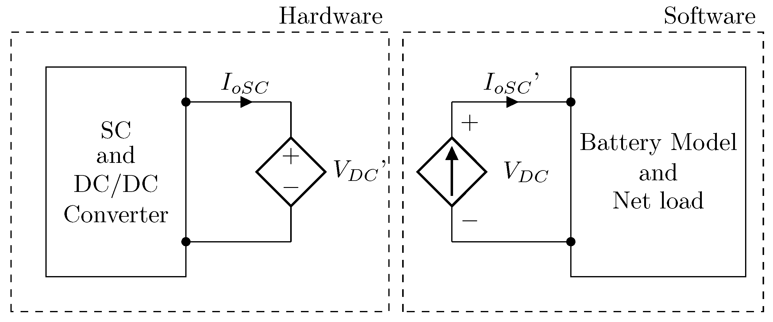
4. PHIL Simulation Setup

The previously described control strategy is validated through both PHIL testing and simulations, using the setup diagram in Figure 2 and the parameters in Table 1.
One of the main challenges in validating control strategies for hybrid storage systems is the need for realistic testing setups [29]. Traditional simulations often fall short in capturing system complexities and interactions. Hardware-in-the-loop (HIL) simulations allow for real-device testing but are limited in handling high-power signals, which necessitates Power Hardware-in-the-Loop (PHIL) tests [30]. PHIL simulations use power amplifiers to convert real-time simulator signals into high-power signals, enabling a controlled interaction environment for various tests [31]. Interface algorithms are crucial in PHIL simulations as they influence stability and accuracy by modifying signal transmission. The Ideal Transformer Model (ITM) algorithm is one of the most commonly used and straightforward approaches for implementing a power HIL simulation. Nevertheless, this algorithm can lead to instabilities in the system representation. Other methods, such as the Time-variant First-order Approximation (TFA) and Partial Circuit Duplication (PCD) algorithms, offer alternative approaches that address some limitations of ITM, particularly in nonlinear systems and high-frequency signal scenarios, enhancing overall system representation [32,33].
To conduct a PHIL simulation, it is essential to first validate the setup with an online simulation model. This model, shown in Figure 5, seeks to replicate the behavior of the test and validate the effectiveness of the interface algorithm. In this specific scenario, the ITM interface algorithm is employed due to its compatibility with the current load. However, for other types of loads, it may be necessary to consider alternative algorithms to enhance system stability [31].
For the online model of HESS, a simulation was conducted using the Matlab/Simulink software, based on the model presented in Figure 2. The elements used in the simulation were selected from the Specialized Power Systems library, which provides predefined models for the battery, supercapacitor, as well as IGBTs and passive elements for the DC/DC converters. The current load was modeled as a current source, and the proposed interface algorithm was implemented. The online Simulink model is available in the following GitHub repository [34].
Once the online simulation model has been validated, the simulated hardware is replaced with the physical hardware. For this purpose the experimental setup, shown in Figure 6, was used for the laboratory tests. The OP8110-3 Power Amplifier and the OP4510 Real-Time Simulator from OPAL-RT are used to obtain the control signals and the current load. Two 12 V lead-acid batteries and a 16 V, 83 F supercapacitor were used for the HESS in the experimental setup. A half-bridge bidirectional DC/DC converter was employed, utilizing an IGBT module SKM400GB066D with the SKYPER 42 R driver.
The power amplifier was operated in current mode to deliver the simulated load current, enabling converter testing. Moreover, it is possible to model various types of loads for rapid validation of different control strategies in a controlled environment.

5. PHIL and Simulation Results

In this section, simulation results and experimental findings are presented based on the proposed strategy outlined in Section 3, along with the guidelines provided in Section 4, aimed at validating the proposed control strategy.

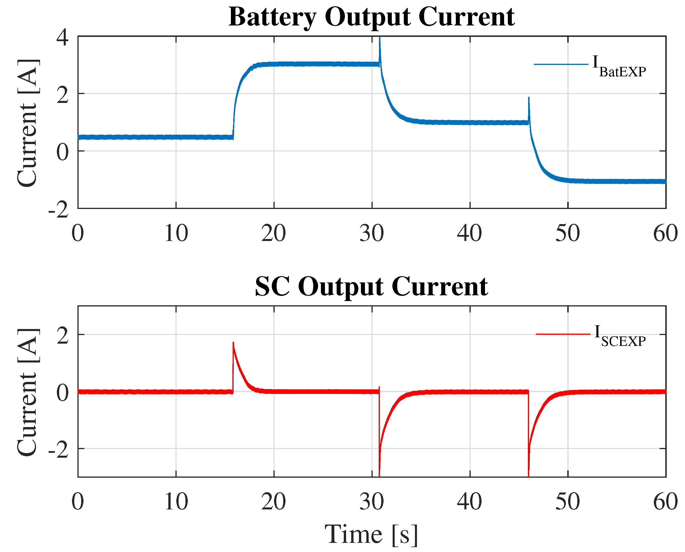
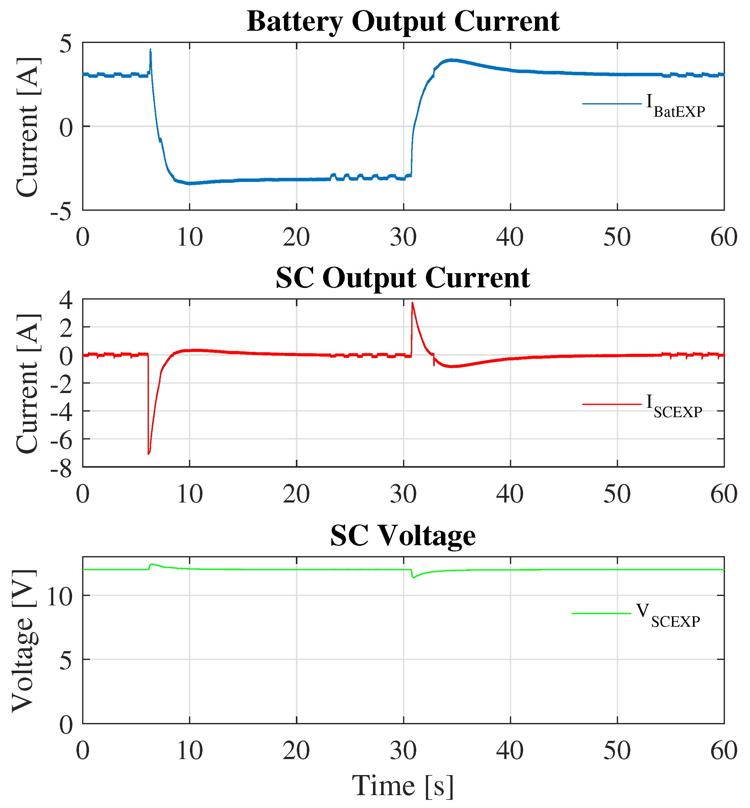
5.1. Simulation Results
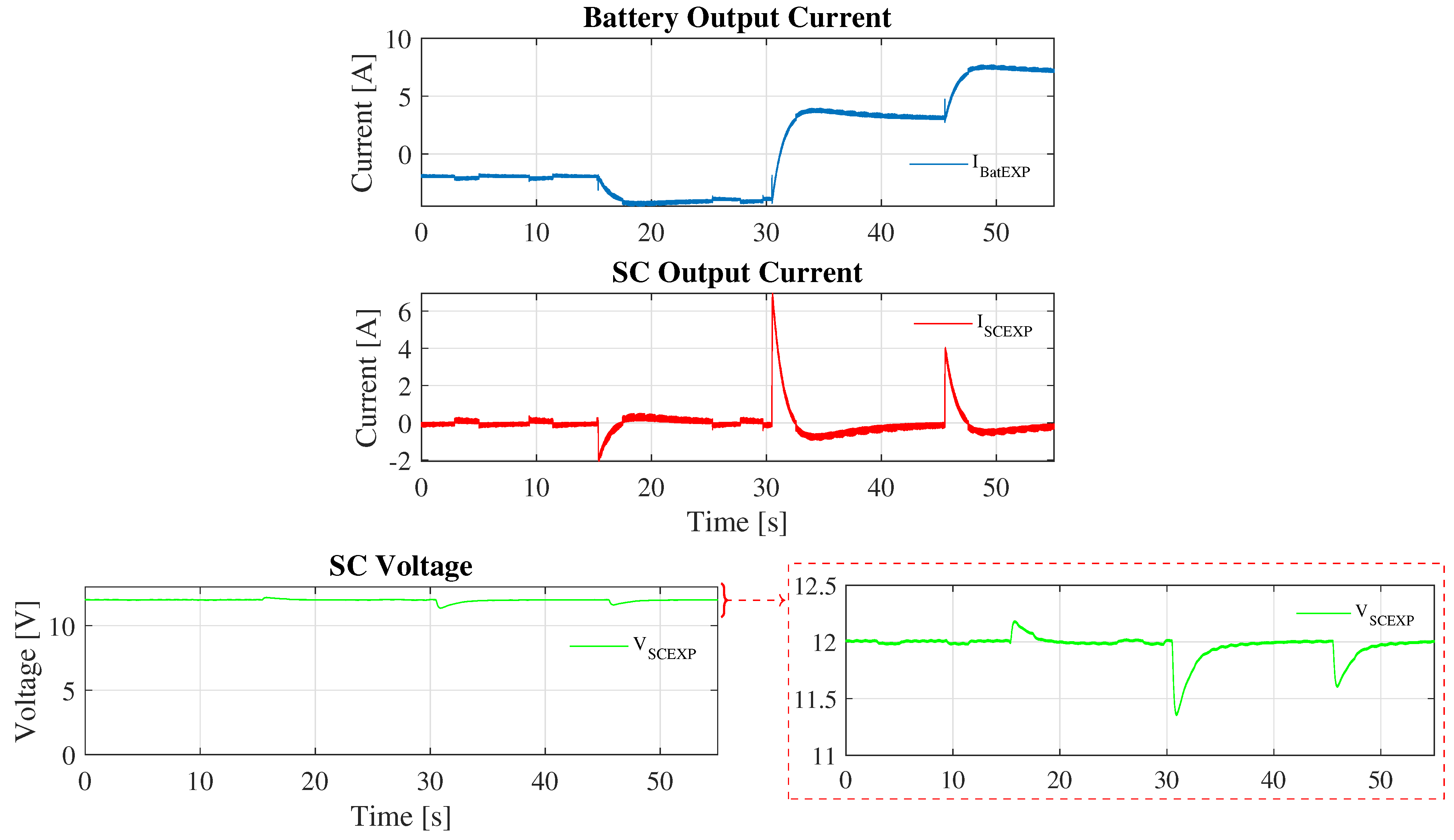
To initially validate the proposed control strategy, two simulations were conducted. The first simulation implemented the passivity-based control (PBC) algorithm and compared it against a PI-control algorithm. The design of the PI controller begins with the averaged model of the system, which is linearized at the desired operating point. The controller parameters, K p and K i , are then tuned to achieve the desired closed-loop response of the system. In this case, the values obtained were K p = 2.5 and K i = 10 . The second simulation examined an enhanced strategy integrating State of Charge (SoC) control. This approach aims to sustain continuous operation under varying load conditions by adjusting the SoC to a reference value.
For the first simulation scenario, Figure 7 depicts the results for both control strategies employing a high-pass filter with a settling time of 5 s. It is observed that during each current change in both strategies, the supercapacitor (SC) promptly responds by supplying current during the transient period. This allows the battery to gradually take over current supply until, in the steady state, all current is sourced by the battery. However, the SC voltage does not maintain the desired value, which, for larger current changes, could pose an issue by pushing the SC voltage outside the operational range.
Upon closer examination of the results, it is observed that the PBC reduces the switching ripple in the output currents of the HESS. Moreover, it operates more efficiently by maintaining a higher voltage level in the SC compared to the PI control. This, coupled with the fact that employing a nonlinear control technique allows for better system operation by not working under a specific operating point, highlights the advantages of PBC. Additionally, the PBC requires only the design of a single constant k, in contrast to the PI control, which requires the design of two parameters, thus complicating the controller’s parameterization.
The second simulation studies the enhanced strategy, which incorporates State of Charge (SoC) control to maintain continuous operation under varying load conditions by adjusting the SoC to a reference value. As shown in Figure 8, the supercapacitor (SC) can supply all required power during each load change, thereby reducing the battery’s burden until reaching the steady state. Additionally, as steady state approaches, the SC charges or discharges in order to achieve the reference SOC, therefore enhancing the DC voltage stability. The plots of the duty cycles in both boost and buck modes are observed, showing that the SC converter adjusts its operating mode to provide the necessary current to the system for different load current changes.

5.2. PHIL Results

Once the model was validated through simulation, we proceeded with testing using the experimental setup described in Section 4. By employing PHIL simulations, we replicated high-power signal interactions and captured the dynamic behavior of the system under realistic operating conditions. This approach enabled a thorough evaluation of the stability, efficiency, and response of the implemented control algorithms, offering valuable insights into the system’s performance during sudden load changes and transient events. Due to the significant volume of generated data files, the validation time for each PHIL test was constrained to one minute.
Figure 9 presents experimental results from the initial test without SC State of Charge (SoC) control. As observed in these results, the SC initially supplies the transient load and then stabilizes at zero, enabling the battery to smoothly deliver the required load current as expected. Despite occasional peaks in battery current due to the boost and buck mode behavior of the converter, the results confirm the effectiveness of the passivity-based control and the suitability of the proposed experimental setup.
Figure 10 displays the experimental results with SoC control implemented. Two load current changes were conducted to validate the operation of the proposed control setup. In this scenario, the SC initially provides the required output current for the load’s transient component, then adjusts its charge or discharge to achieve the desired SoC within the specified timeframe, eventually stabilizing at zero current. Concurrently, the battery smoothly increases its supply current until reaching steady state, where it meets the total load current demand.
To further validate the proposed control strategy and assess the effectiveness of using the PHIL methodology, a third experimental setup was conducted. In this setup, depicted in Figure 11, the battery equivalent was modeled inside the real-time simulator to enhance the battery model used during experimental testing. The real-time simulator utilizes the same battery model available in the Simulink library used for computer simulations, specifically designed to simulate a lithium battery with a nominal voltage of 24 V and a capacity of 100 Ah. To implement this change in the real-time simulator’s internal model, modifications were made to the interface algorithm, transitioning from a current source equivalent model to a voltage source model. This adjustment ensures that the output voltage from the power amplifier panel matches the internal voltage of the battery model.
Figure 12 illustrates the results corresponding to the aforementioned modifications. The results show a consistent behavior with the previous case: the battery reaches the load current value without experiencing transients, successfully achieving the SoC regulation objective. This not only highlights the improved performance of the proposed strategy but also underscores the effectiveness of employing a real-time simulator for PHIL simulations. This approach allows testing of setups without physically deploying batteries, thereby reducing costs associated with validating control strategies.

6. Conclusions

This paper introduces a passivity-based control (PBC) approach combined with filtering for a semi-active Hybrid Energy Storage System (HESS) employing supercapacitors (SCs). The PBC approach outperforms conventional PI control methods by effectively addressing system nonlinearities, minimizing current ripple, and improving voltage regulation. Additionally, the integration of an SC voltage control strategy effectively decouples voltage regulation from current control, ensuring smooth operation during load transients and maintaining SC operation within specified voltage limits. Validation of the proposed control algorithm was conducted through simulations and Power Hardware-in-the-Loop (PHIL) testing under realistic conditions, closely mirroring practical applications. The PHIL methodology streamlined the validation process by simulating various system components, such as batteries and loads, reducing the requirement for extensive equipment and simplifying setup complexities. These comprehensive tests underscore the robustness and efficacy of the proposed control strategy for SC semi-active configurations, affirming its ability to manage diverse load conditions while ensuring system stability and efficiency.
To further enhance the performance of the employed control technique, future work will focus on the integration of estimators for state variables, system parameters, and system load. This improvement aims to provide more accurate and robust control under varying operational conditions. Additionally, the design and implementation of other nonlinear control strategies and converter topologies will be explored. These advanced techniques have the potential to significantly improve the system’s behavior, offering better stability, efficiency, and responsiveness to dynamic changes. Furthermore, this work can be extended to other applications, such as electric mobility, where including models of associated loads, such as electric motors, can be particularly beneficial.

Author Contributions

Conceptualization, F.F.-R., M.A.-I., D.R.-Q., W.M. and C.A.C.; formal analysis, F.F.-R.; funding acquisition, D.R.-Q. and C.A.C.; methodology, F.F.-R.; software, F.F.-R.; supervision, M.A.-I., D.R.-Q., W.M. and C.A.C.; validation, F.F.-R. and M.A.-I.; writing—original draft, F.F.-R.; writing—review and editing, M.A.-I., D.R.-Q., W.M. and C.A.C. All authors have read and agreed to the published version of the manuscript.

Funding

This work was funded by the Colombian Government through the Sistema general de Regalías (SGR), within the project: Diseño e implementación de microrredes eléctricas para garantizar la calidad del suministro en cargas críticas del Vichada-BPIN 2020000100064.

Data Availability Statement

Data are contained within the article.

Acknowledgments

We extend our sincere gratitude to the Universidad Nacional de Colombia, with special appreciation to the research group EMC-UN and the laboratory “Laboratorio de Innovación en Alta Tensión y Energías Renovables (LIATER)” for their invaluable support and provision of facilities.

Conflicts of Interest

The authors declare no conflicts of interest. The funders had no role in the design of the study; in the collection, analyses, or interpretation of data; in the writing of the manuscript; or in the decision to publish the results.

References

  1. Peñaranda, A.F.; Romero-Quete, D.; Cortés, C.A. Grid-scale battery energy storage for arbitrage purposes: A Colombian case. Batteries 2021, 7, 59. [Google Scholar] [CrossRef]
  2. Hajiaghasi, S.; Salemnia, A.; Hamzeh, M. Hybrid energy storage system for microgrids applications: A review. J. Energy Storage 2019, 21, 543–570. [Google Scholar] [CrossRef]
  3. Zhang, L.; Hu, X.; Wang, Z.; Sun, F.; Dorrell, D.G. A review of supercapacitor modeling, estimation, and applications: A control/management perspective. Renew. Sustain. Energy Rev. 2018, 81, 1868–1878. [Google Scholar] [CrossRef]
  4. Babu, T.S.; Vasudevan, K.R.; Ramachandaramurthy, V.K.; Sani, S.B.; Chemud, S.; Lajim, R.M. A Comprehensive Review of Hybrid Energy Storage Systems: Converter Topologies, Control Strategies and Future Prospects. IEEE Access 2020, 8, 148702–148721. [Google Scholar] [CrossRef]
  5. Lin, X.; Zamora, R. Controls of hybrid energy storage systems in microgrids: Critical review, case study and future trends. J. Energy Storage 2022, 47, 103884. [Google Scholar] [CrossRef]
  6. Narvaez, A.; Cortes, C.; Trujillo, C.L. Topologies for Battery and Supercapacitor Interconnection in Residential Microgrids with Intermittent Generation. Ingeniería 2020, 25, 6–19. [Google Scholar] [CrossRef]
  7. Mali, V.; Tripathi, B.; Kumar, K.; Dwivedi, S.; Behera, R. Exploring various Topology using DC-DC Converter in Hybrid Energy Storage System for Electric Vehicles. In Proceedings of the IECON 2022—48th Annual Conference of the IEEE Industrial Electronics Society, Brussels, Belgium, 17–20 October 2022; pp. 1–6. [Google Scholar] [CrossRef]
  8. Takrouri, M.A.; Ayob, S.M.; Idris, N.R.N.; Aziz, M.J.A.; Ayop, R.; Said, M.F.B.M. Comparative Analysis of Passive and Semi-active Hybrid Energy Storage System Topologies for Electric Vehicle. In Proceedings of the 2023 IEEE Conference on Energy Conversion (CENCON), Kuching, Malaysia, 23–24 October 2023; pp. 75–80. [Google Scholar] [CrossRef]
  9. Rout, T.; Maharana, M.K.; Chowdhury, A.; Samal, S. A Comparative study of Stand-alone Photo-Voltaic System with Battery storage system and Battery Supercapacitor storage system. In Proceedings of the 2018 4th International Conference on Electrical Energy Systems (ICEES), Chennai, India, 7–9 February 2018; pp. 77–81. [Google Scholar] [CrossRef]
  10. Shchur, I.; Biletskyi, Y. Interconnection and damping assignment passivity-based control of semi-active and active battery/supercapacitor hybrid energy storage systems for stand-alone photovoltaic installations. In Proceedings of the 2018 14th International Conference on Advanced Trends in Radioelecrtronics, Telecommunications and Computer Engineering (TCSET), Lviv-Slavske, Ukraine, 20–24 February 2018; pp. 324–329. [Google Scholar] [CrossRef]
  11. Aharon, I.; Kuperman, A. Design of semi-active battery-ultracapacitor hybrids. In Proceedings of the 2010 IEEE 26th Convention of Electrical and Electronics Engineers in Israel, Eilat, Israel, 17–20 November 2010; pp. 000593–000597. [Google Scholar] [CrossRef]
  12. Lerman, C.; Horosov, A.; Kuperman, A. Capacitor semi-active battery-ultracapacitor hybrid energy source. In Proceedings of the 2012 IEEE 27th Convention of Electrical and Electronics Engineers in Israel, Eilat, Israel, 14–17 November 2012; pp. 1–4. [Google Scholar] [CrossRef]
  13. Yuhimenko, V.; Lerman, C.; Kuperman, A. DC Active Power Filter-Based Hybrid Energy Source for Pulsed Power Loads. IEEE J. Emerg. Sel. Top. Power Electron. 2015, 3, 1001–1010. [Google Scholar] [CrossRef]
  14. Asensio, M.E.M.; Magallán, G.A.; Angelo, C.H.D. Control de un Sistema Híbrido de Almacenamiento de Energía para vehículos eléctricos. In Proceedings of the 2014 IEEE Biennial Congress of Argentina (ARGENCON), Bariloche, Argentina, 11–13 June 2014; pp. 570–575. [Google Scholar] [CrossRef]
  15. Kozhushko, Y.; Karbivska, T.; Pavković, D.; Bondarenko, O. Peak Current Control of Battery-Supercapacitor Hybrid Energy Storage. In Proceedings of the 2020 IEEE KhPI Week on Advanced Technology (KhPIWeek), Kharkiv, Ukraine, 5–10 October 2020; pp. 396–401. [Google Scholar] [CrossRef]
  16. Bhattacharyya, P.; Banerjee, A.; Sen, S.; Giri, S.K.; Sadhukhan, S. A Modified Semi-Active Topology for Battery-Ultracapacitor Hybrid Energy Storage System for EV Applications. In Proceedings of the 2020 IEEE International Conference on Power Electronics, Smart Grid and Renewable Energy (PESGRE2020), Cochin, India, 2–4 January 2020; pp. 1–6. [Google Scholar] [CrossRef]
  17. Zhang, Q.; Li, G. Experimental Study on a Semi-Active Battery-Supercapacitor Hybrid Energy Storage System for Electric Vehicle Application. IEEE Trans. Power Electron. 2020, 35, 1014–1021. [Google Scholar] [CrossRef]
  18. Asensio, M.; Magallán, G.; Angelo, C.D. Control por modos deslizantes de un Sistema Híbrido de Almacenamiento de Energía para vehículos eléctricos. In Proceedings of the 2016 IEEE Biennial Congress of Argentina (ARGENCON), Buenos Aires, Argentina, 15–17 June 2016; pp. 1–6. [Google Scholar] [CrossRef]
  19. Russo, A.; Cavallo, A. Supercapacitor stability and control for More Electric Aircraft application. In Proceedings of the 2020 European Control Conference (ECC), St. Petersburg, Russia, 12–15 May 2020; pp. 1909–1914. [Google Scholar]
  20. Trovao, J.P.; Dubois, M.R.; Gomozov, O.; Kestelyn, X.; Bouscayrol, A. A Model Predictive Control with Non-Uniform Sampling Times for a Hybrid Energy Storage System in Electric Vehicle Application. In Proceedings of the 2015 IEEE Vehicle Power and Propulsion Conference (VPPC), Montreal, QC, Canada, 19–22 October 2015; pp. 1–6. [Google Scholar] [CrossRef]
  21. Yi, F.; Lu, D.; Wang, X.; Pan, C.; Tao, Y.; Zhou, J.; Zhao, C. Energy Management Strategy for Hybrid Energy Storage Electric Vehicles Based on Pontryagin’s Minimum Principle Considering Battery Degradation. Sustainability 2022, 14, 1214. [Google Scholar] [CrossRef]
  22. Xu, Q.; Xiao, J.; Wang, P.; Pan, X.; Wen, C. A Decentralized Control Strategy for Autonomous Transient Power Sharing and State-of-Charge Recovery in Hybrid Energy Storage Systems. IEEE Trans. Sustain. Energy 2017, 8, 1443–1452. [Google Scholar] [CrossRef]
  23. Ortega, R.; García-Canseco, E. Interconnection and Damping Assignment Passivity-Based Control: A Survey. Eur. J. Control 2004, 10, 432–450. [Google Scholar] [CrossRef]
  24. Ortega, R.; Loria, A.; Nicklasson, P.J.; Sira-Ramirez, H. Passivity-Based Control of Euler-Lagrange Systems; Springer: London, UK, 1998. [Google Scholar] [CrossRef]
  25. Beltrán, C.A.; Diaz-Saldierna, L.H.; Langarica-Cordoba, D.; Martinez-Rodriguez, P.R. Passivity-Based Control for Output Voltage Regulation in a Fuel Cell/Boost Converter System. Micromachines 2023, 14, 187. [Google Scholar] [CrossRef] [PubMed]
  26. Bacha, S.; Munteanu, I.; Bratcu, A.I. Power Electronic Converters Modeling and Control; Springer: London, UK, 2014. [Google Scholar] [CrossRef]
  27. Asensio, M.; Magallán, G.; Amaya, G.; Angelo, C.D. Efficiency and Performance Analysis of Battery-Ultracapacitor based Semi-active Hybrid Energy Systems for Electric Vehicles. IEEE Lat. Am. Trans. 2018, 16, 2581–2590. [Google Scholar] [CrossRef]
  28. Cabrane, Z.; Lee, S.H. Electrical and Mathematical Modeling of Supercapacitors: Comparison. Energies 2022, 15, 693. [Google Scholar] [CrossRef]
  29. Sparn, B.; Krishnamurthy, D.; Pratt, A.; Ruth, M.; Wu, H. Hardware-in-the-Loop (HIL) Simulations for Smart Grid Impact Studies. In Proceedings of the 2018 IEEE Power & Energy Society General Meeting (PESGM), Portland, OR, USA, 5–10 August 2018; pp. 1–5. [Google Scholar] [CrossRef]
  30. Viehweider, A.; Lauss, G.; Felix, L. Stabilization of Power Hardware-in-the-Loop simulations of electric energy systems. Simul. Model. Pract. Theory 2011, 19, 1699–1708. [Google Scholar] [CrossRef]
  31. Lauss, G.F.; Faruque, M.O.; Schoder, K.; Dufour, C.; Viehweider, A.; Langston, J. Characteristics and Design of Power Hardware-in-the-Loop Simulations for Electrical Power Systems. IEEE Trans. Ind. Electron. 2016, 63, 406–417. [Google Scholar] [CrossRef]
  32. Ren, W.; Steurer, M.; Baldwin, T.L. Improve the Stability and the Accuracy of Power Hardware-in-the-Loop Simulation by Selecting Appropriate Interface Algorithms. In Proceedings of the 2007 IEEE/IAS Industrial & Commercial Power Systems Technical Conference, Edmonton, AB, Canada, 6–11 May 2007; pp. 1–7. [Google Scholar] [CrossRef]
  33. Marks, N.D.; Kong, W.Y.; Birt, D.S. Stability of a Switched Mode Power Amplifier Interface for Power Hardware-in-the-Loop. IEEE Trans. Ind. Electron. 2018, 65, 8445–8454. [Google Scholar] [CrossRef]
  34. Fracica-Rodriguez, F.; Acevedo-Iles, M.; Romero-Quete, D.; Martinez, W.; Cortes, C.A. Simulink Model for a Hybrid Energy Storage System in Semi-Active Topology. 2024. Available online: https://github.com/ffracica/PBC-semiactive-HESS.git (accessed on 1 July 2024).
Figure 1. Schematic diagram of the semi-active HESS.
Batteries 10 00322 g001
Figure 2. HESS model in semi-active topology.
Batteries 10 00322 g002
Figure 3. Proposed control scheme.
Batteries 10 00322 g003
Figure 4. Step response for the proposed SoC restoration strategy.
Batteries 10 00322 g004
Figure 5. Configuration of a PHIL simulation with ITM.
Batteries 10 00322 g005
Figure 6. Experimental setup.
Batteries 10 00322 g006
Figure 7. Simulation result without SoC restoration.
Batteries 10 00322 g007
Figure 8. Simulation result with SoC restoration.
Batteries 10 00322 g008
Figure 9. PHIL validation result without SoC restoration.
Batteries 10 00322 g009
Figure 10. PHIL validation result with SoC Restoration.
Batteries 10 00322 g010
Figure 11. PHIL configuration with internal battery and load model.
Batteries 10 00322 g011
Figure 12. PHIL validation result with SoC Restoration and internal battery model.
Batteries 10 00322 g012
Table 1. System parameters.
VariableDescriptionValue
V B a t Battery nominal voltage24 V
V S C SC nominal voltage16 V
C S C SC capacitance83 F
V S C * V S C Reference value12 V
F s Switching frequency35 kHz
L B a t Battery inductor4 mH
L S C SC converter inductor0.5 mH
C o u t Converter output capacitor4700 μF
kPBC gain100
Disclaimer/Publisher’s Note: The statements, opinions and data contained in all publications are solely those of the individual author(s) and contributor(s) and not of MDPI and/or the editor(s). MDPI and/or the editor(s) disclaim responsibility for any injury to people or property resulting from any ideas, methods, instructions or products referred to in the content.

