
Advancements and Applications of Redox Flow Batteries in Australia


Abstract

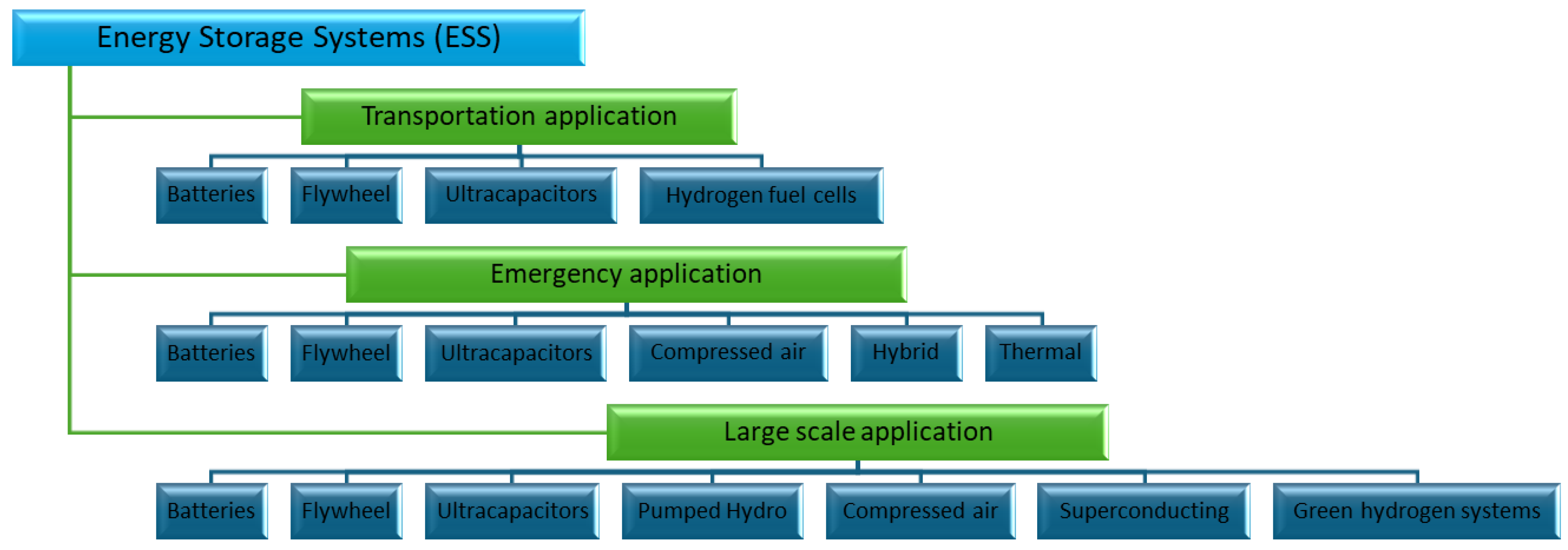
1. Introduction
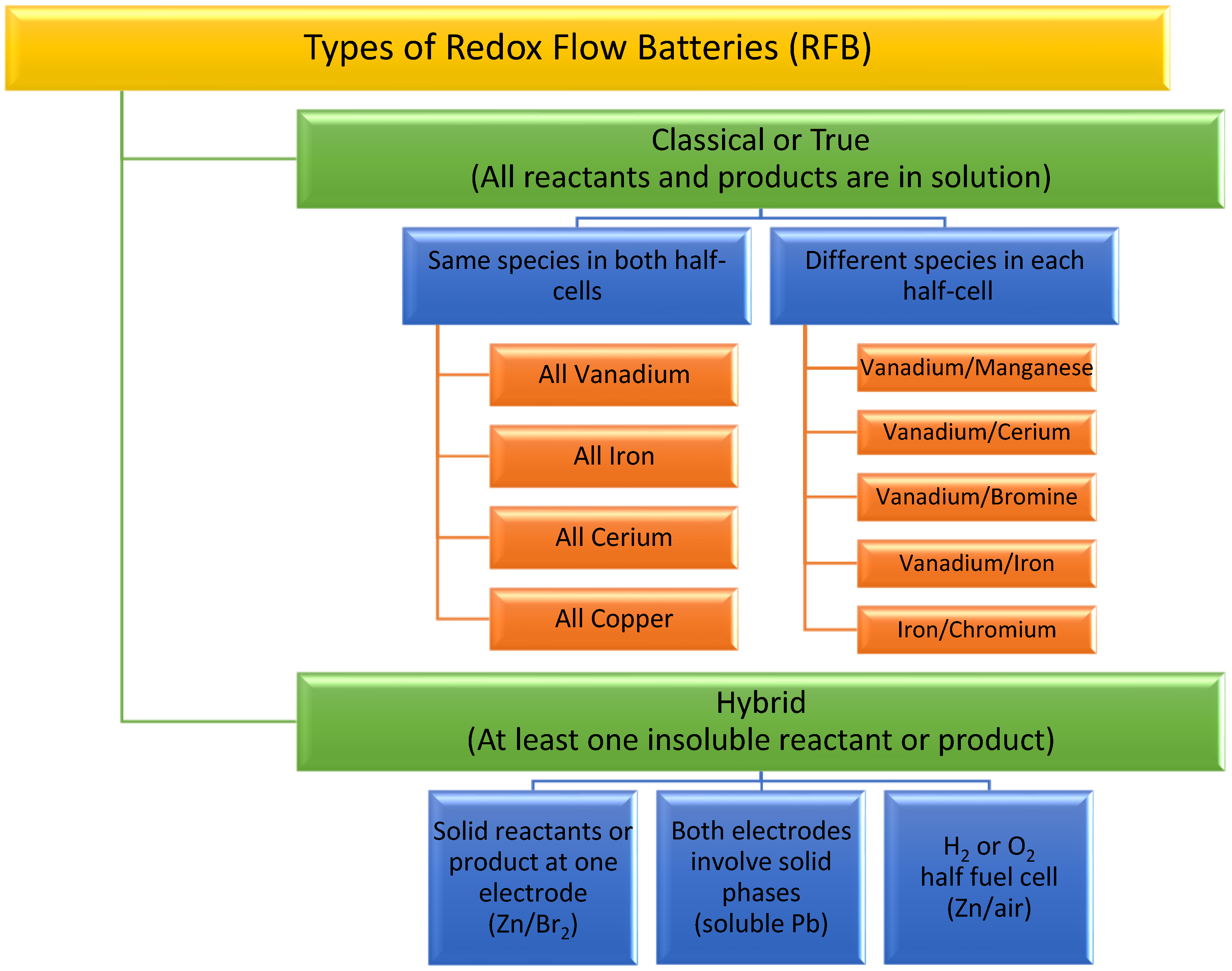
2. Redox Flow Batteries (RFBs)
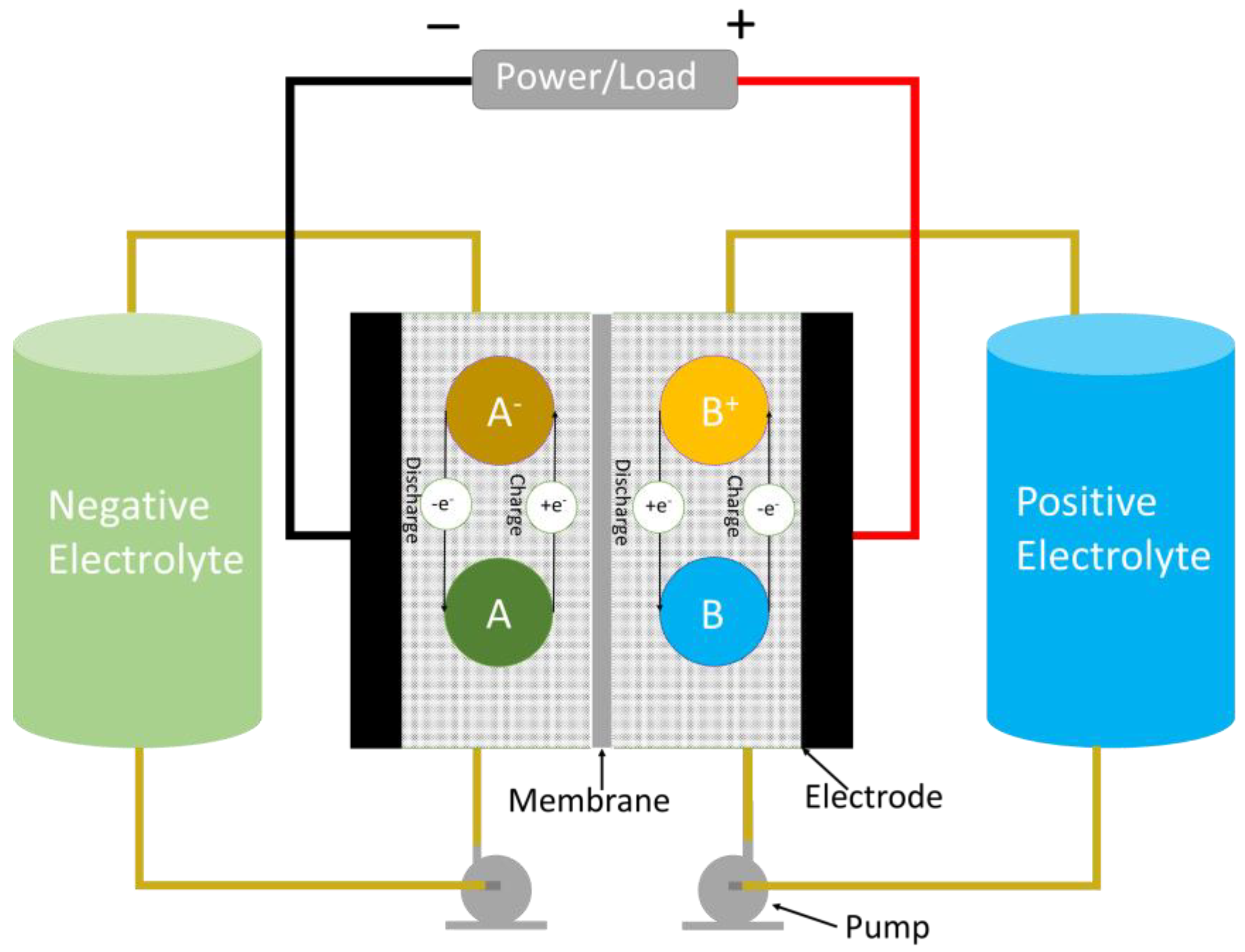
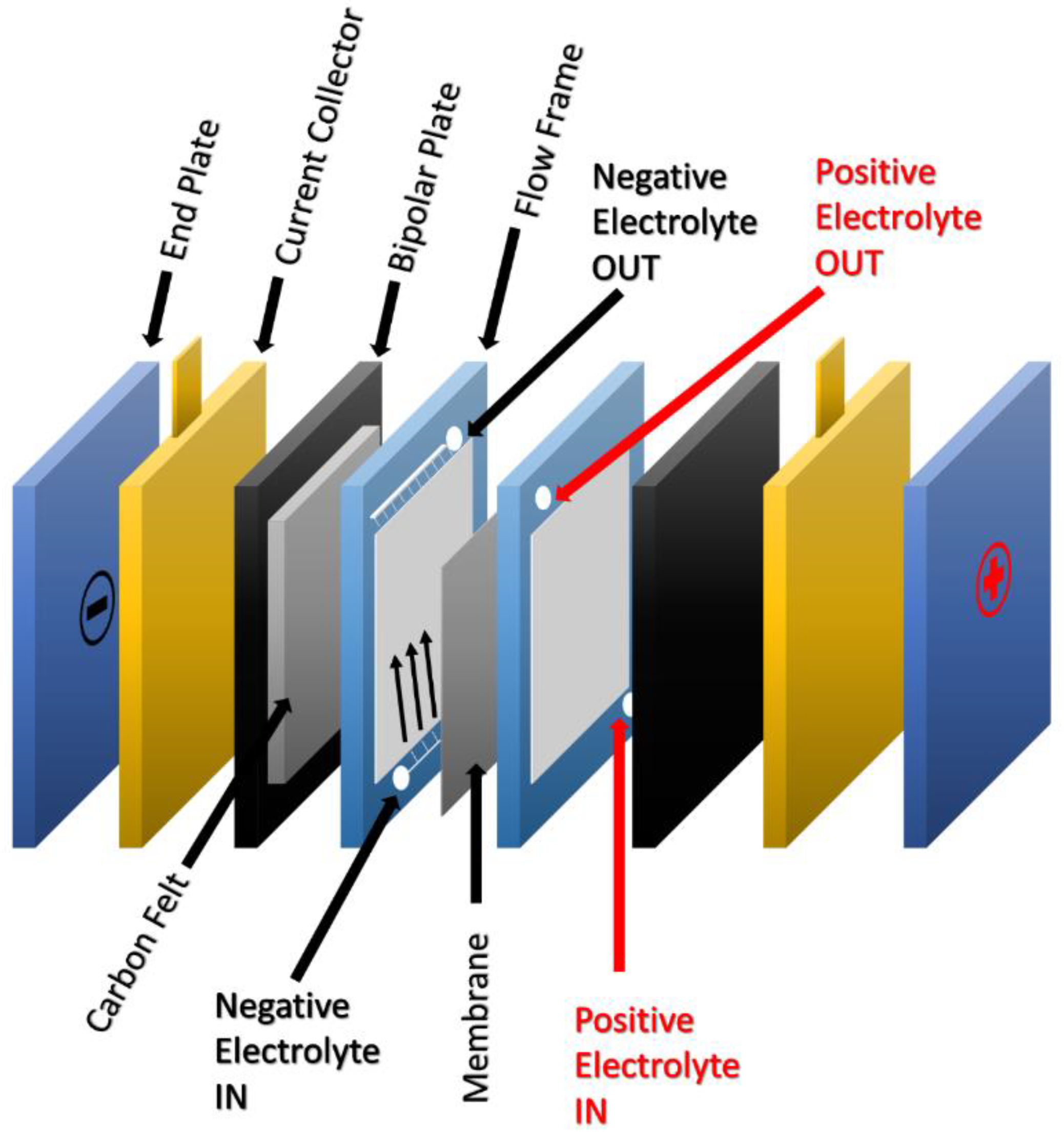
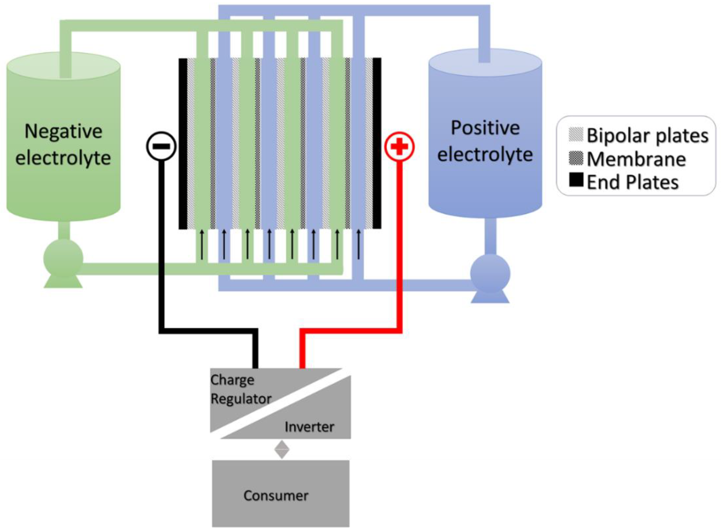
2.1. Basic Construction
2.2. Redox Flow Battery Chemistry
2.3. Energy Efficiency
3. Classical RFBs
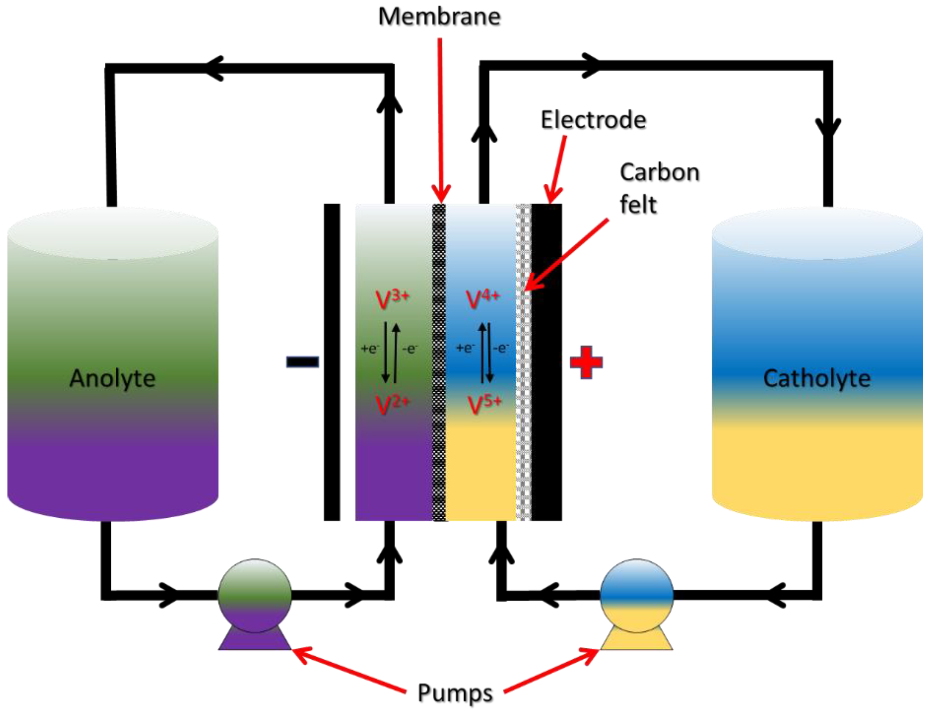
3.1. All-Vanadium RFBs
3.1.1. Chemistry of VRFB
3.1.2. Different VRFB Generation Chemistries
3.1.3. Advantages and Disadvantages
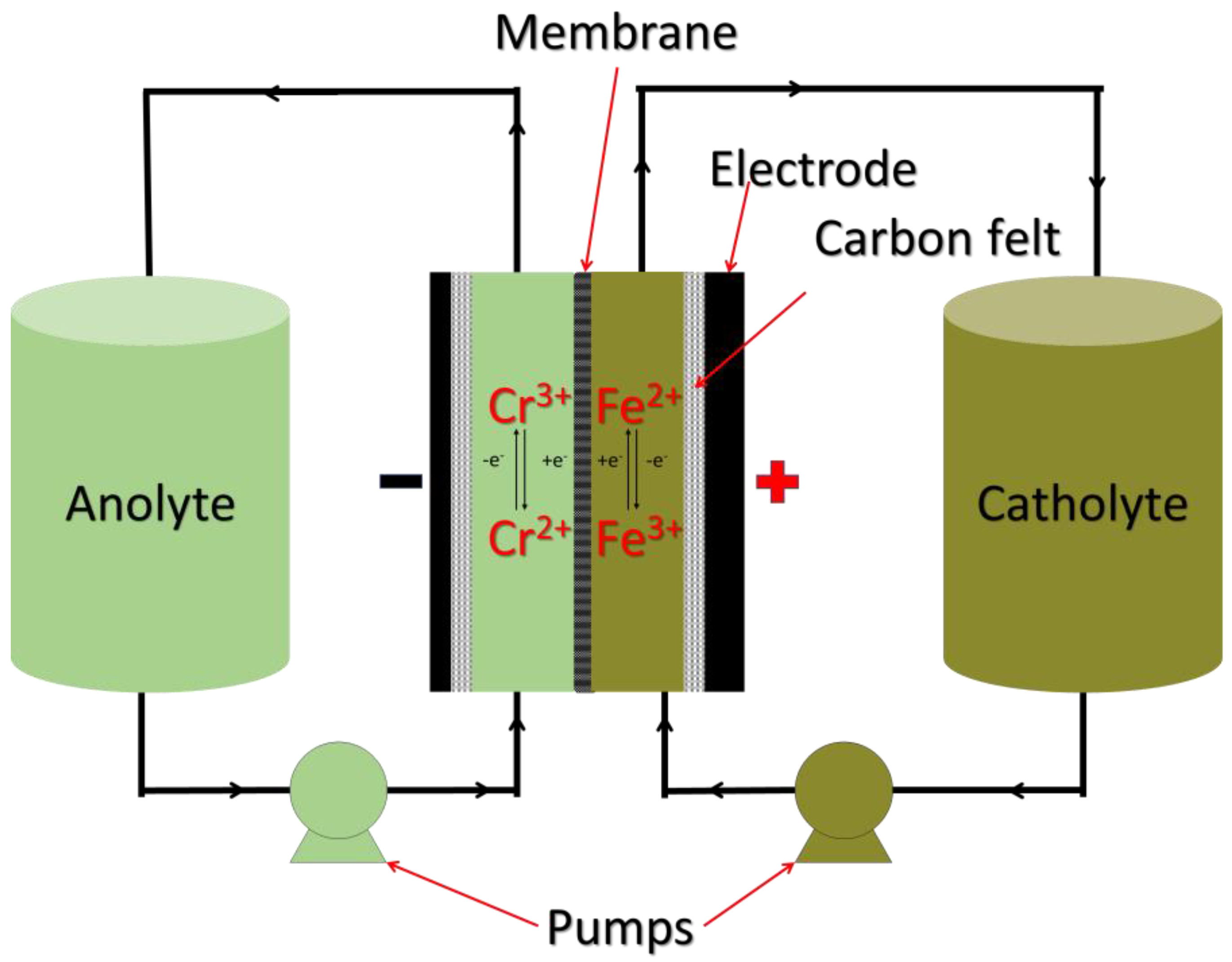
3.2. Iron Chromium RFBs
3.2.1. Chemistry of Iron Chromium RFBs
3.2.2. Advantages and Disadvantages
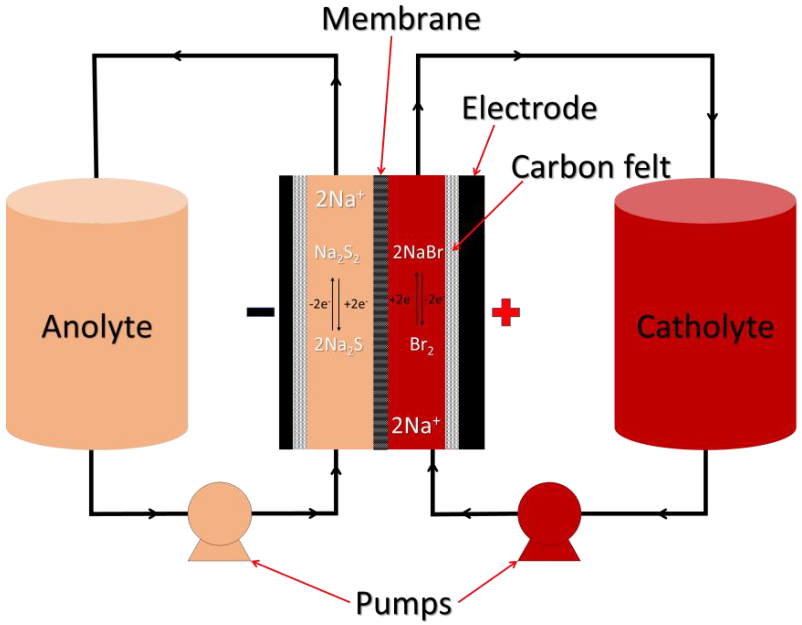
3.3. Polysulphide RFBs
3.3.1. Chemistry of Polysulphide RFBs
All Liquid PSRFBs
Hybrid PSRFBs
Liquid/Gas PSRFBs
3.3.2. Advantages and Disadvantages
3.4. Organic RFBs
4. Hybrid RFBs
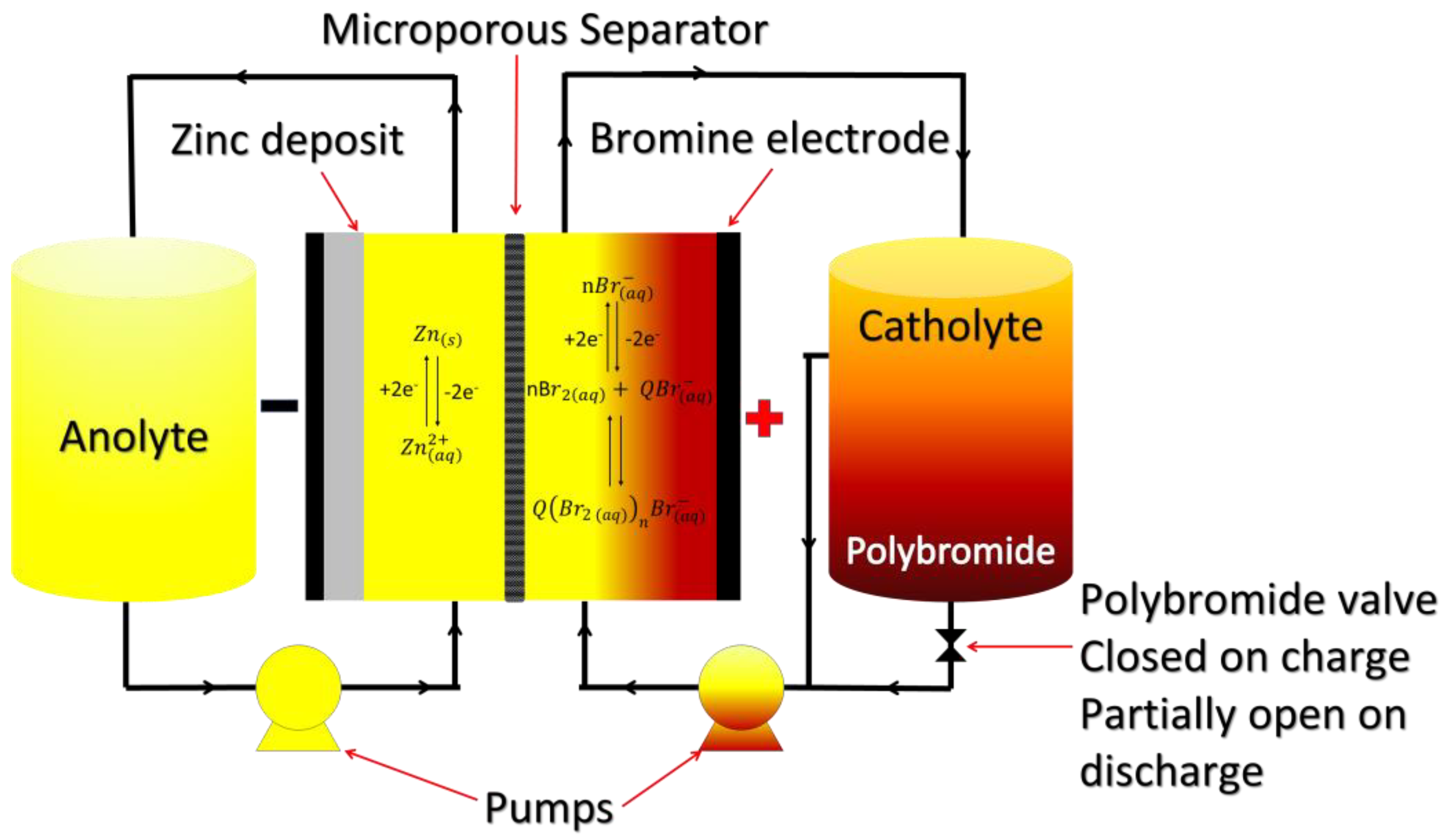
4.1. Zinc Bromine RFBs
4.1.1. Chemistry of Zinc Bromine RFBs
4.1.2. Advantages and Disadvantages
4.1.3. Alternatives to ZBFB
4.2. All-Iron RFBs
4.2.1. Chemistry of All-Iron RFBs
Hybrid AIRFBs
Aqueous AIRFBs
4.2.2. Advantages and Disadvantages
5. Suitability for Sustainable Powering of Australia
5.1. Pumped Hydro Energy Storage
5.2. Solid Gravity Energy Storage Systems
5.3. Fly Wheel Energy Storage
5.4. Green Hydrogen Energy Storage
5.5. Batteries
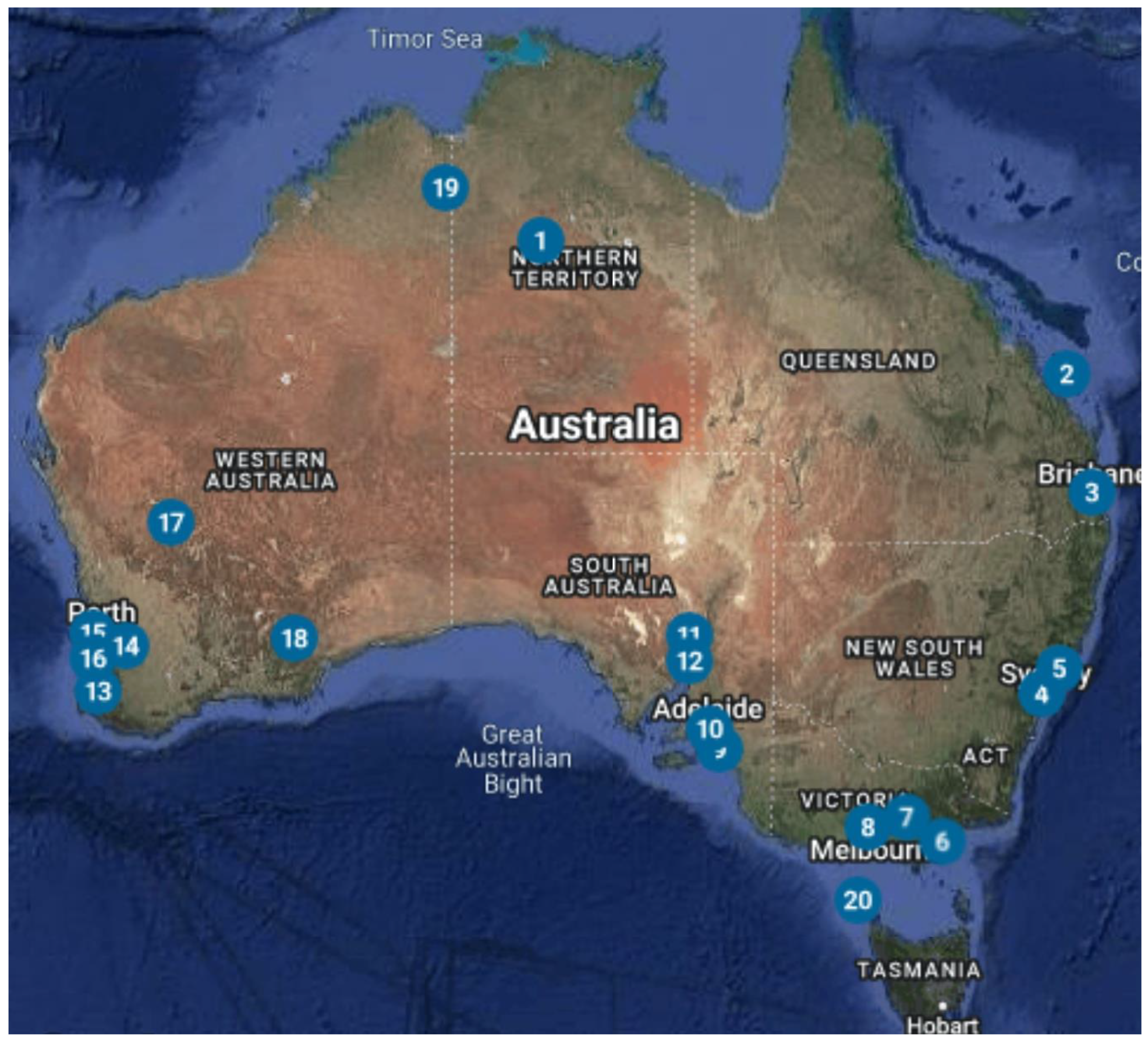
5.6. Redox Flow Batteries in Australia
- Long Cycle Life: RFBs typically have long cycle lives, often exceeding 20,000 cycles [113], reducing the need for frequent replacements and lowering the overall cost of energy storage. In comparison, lithium batteries have a 3000-cycle lifespan at an 80% deep discharge [119]. VRFBs are suggested to be more efficient in hot climates, where lithium batteries age faster and incur higher long-term costs due to the increased temperatures [244].
- Scalability: RFBs are highly scalable, allowing users to adjust the system size to meet their specific energy storage needs by increasing the electrolyte volume. This flexibility can lead to cost savings by avoiding the over-sizing of storage systems [244].
- Low Maintenance: RFBs need less upkeep than many other energy storage technologies. Separating the electrolyte storage from the cell makes maintenance simpler, lowering operational costs.
- Environmental Impact: RFBs can be more environmentally friendly. For example, VRFBs use vanadium, which is relatively abundant and efficiently recyclable. In contrast, the recycling processes for other battery technologies, such as lithium batteries, pose higher risks, including an increased risk of combustion, greater environmental impact, and more complexity [249,250].
6. Conclusions
Funding
Conflicts of Interest
References
- Yang, Z.; Liu, J.; Baskaran, S.; Imhoff, C.H.; Holladay, J.D. Enabling Renewable Energy-and the Future Grid-with Advanced Electricity Storage. JOM 2010, 62, 14–23. [Google Scholar] [CrossRef]
- Gajdzik, B.; Wolniak, R.; Nagaj, R.; Žuromskaitė-Nagaj, B.; Grebski, W.W. The Influence of the Global Energy Crisis on Energy Efficiency: A Comprehensive Analysis. Energies 2024, 17, 947. [Google Scholar] [CrossRef]
- Nikoloski, A.; Issa, T.B. Development of Electrolytes for Vanadium Redox Flow Batteries; Future Battery Industries CRC: Bentley, Australia, 2023. [Google Scholar]
- Martins, F.; Felgueiras, C.; Smitkova, M.; Caetano, N. Analysis of Fossil Fuel Energy Consumption and Environmental Impacts in European Countries. Energies 2019, 12, 964. [Google Scholar] [CrossRef]
- Hai, T.; Ali, M.A.; Zeki, F.M.; Chauhan, B.S.; Metwally, A.S.M.; Ullah, M. Optimal design of inter-state hydrogen fuel cell vehicle fueling station with on-site hydrogen production. Int. J. Hydrogen Energy 2024, 52, 733–745. [Google Scholar] [CrossRef]
- van den Bergh, J.C.J.M.; Botzen, W.J.W. Monetary valuation of the social cost of CO2 emissions: A critical survey. Ecol. Econ. 2015, 114, 33–46. [Google Scholar] [CrossRef]
- Khan, S.A.; Chakraborty, S.; Dash, K.K.; Dar, A.H.; Shawl, F.; Dash, S.K.; Singh, S.K.; Dwivedi, M.; Barik, D. Review of Solar Greenhouse Drying Systems in Conjunction with Hybrid Technological Features, Designs, Operations, and Economic Implications for Agro-Food Product Processing Application. Energy Technol. 2024, 12, 2400176. [Google Scholar] [CrossRef]
- Houghton, J.T.; Jenkins, G.J.; Ephraums, J.J. Climate Change: The IPCC Scientific Assessment; Houghton, J.T., Jenkins, G.J., Ephraums, J.J., Eds.; The United Nations: New York, NY, USA, 1993. [Google Scholar]
- Qiao, D.; Luo, Y.; Chu, Y.; Zhang, H.; Zhao, F. Decomposition of agriculture-related non-CO2 greenhouse gas emissions in Chengdu: 1995–2020. J. Clean. Prod. 2024, 434, 140125. [Google Scholar] [CrossRef]
- Boretti, A. Flow batteries for net zero in New Zealand. Energy Storage 2023, 5, e513. [Google Scholar] [CrossRef]
- Gielen, D.; Boshell, F.; Saygin, D.; Bazilian, M.D.; Wagner, N.; Gorini, R. The role of renewable energy in the global energy transformation. Energy Strategy Rev. 2019, 24, 38–50. [Google Scholar] [CrossRef]
- Kiasari, M.; Ghaffari, M.; Aly, H. A Comprehensive Review of the Current Status of Smart Grid Technologies for Renewable Energies Integration and Future Trends: The Role of Machine Learning and Energy Storage Systems. Energies 2024, 17, 4128. [Google Scholar] [CrossRef]
- REN21. Renewables 2022 Global Status Report. 2022. Available online: https://www.ren21.net/gsr-2022/ (accessed on 5 September 2023).
- REN21. Renewables 2024 Global Status: Report Collection, Global Overview; Secretariat, R., Ed.; REN21: Paris, France, 2024. [Google Scholar]
- Australian Department of Climate Change, Energy, the Environment and Water. Solar PV and Batteries. 2023. Available online: https://www.energy.gov.au/households/solar-pv-and-batteries#:~:text=Australia (accessed on 5 September 2023).
- Root, C.; Presume, H.; Proudfoot, D.; Willis, L.; Masiello, R. Using battery energy storage to reduce renewable resource curtailment. In IEEE Power & Energy Society Innovative Smart Grid Technologies Conference (ISGT); IEEE: Washington, DC, USA, 2017; pp. 1–5. [Google Scholar]
- Saka, S. An Overview of Large-Scale Energy Storage Systems. In Advanced Redox Flow Technology; John Wiley & Sons, Inc.: Hoboken, NJ, USA, 2024; pp. 199–243. [Google Scholar]
- National Research Council. The National Academies Summit on America’s Energy Future: Summary of a Meeting; The National Academies Press: Washington, DC, USA, 2008. [Google Scholar]
- Muzammal Islam, M.; Yu, T.; Giannoccaro, G.; Mi, Y.; la Scala, M.; Nasab, M.R.; Wang, J. Improving Reliability and Stability of the Power Systems: A Comprehensive Review on the Role of Energy Storage Systems to Enhance Flexibility. IEEE Access 2024, 12, 152738–152765. [Google Scholar] [CrossRef]
- Patrick, A.; Thompson, B. WA pays business to consume power. In The Australian Financial Review; Fairfax Media Publications Pty Limited: Melbourne, Australia, 2020. [Google Scholar]
- Falope, T.; Lao, L.; Hanak, D.; Huo, D. Hybrid energy system integration and management for solar energy: A review. Energy Convers. Manag. X 2024, 21, 100527. [Google Scholar] [CrossRef]
- Breeze, P. Power System Energy Storage Technologies; Elsevier Science: Amsterdam, The Netherlands, 2018. [Google Scholar]
- Shahzad, S.; Abbasi, M.A.; Shahid, M.B.; Guerrero, J.M. Unlocking the potential of long-duration energy storage: Pathways to net-zero emissions through global innovation and collaboration. J. Energy Storage 2024, 97, 112904. [Google Scholar] [CrossRef]
- Servin-Balderas, I.; Wetser, K.; Heijne, A.T.; Buisman, C.; Hamelers, B. CO2-based methane: An overlooked solution for the energy transition. Energy Sustain. Soc. 2024, 14, 57. [Google Scholar] [CrossRef]
- Zhu, D.; Wang, Y.; Yue, S.; Xie, Q.; Pedram, M.; Chang, N. Maximizing return on investment of a grid-connected hybrid electrical energy storage system. In Proceedings of the 2013 18th Asia and South Pacific Design Automation Conference (ASP-DAC), Yokohama, Japan, 22–25 January 2013. [Google Scholar]
- Abdi, H.; Mohammadi-ivatloo, B.; Javadi, S.; Khodaei, A.R.; Dehnavi, E. Energy storage systems. In Distributed Generation Systems; Gharehpetian, G.B., Agah, M.M., Eds.; Elsevier Inc.: Amsterdam, The Netherlands, 2017; pp. 333–368. [Google Scholar]
- Metals, T. TMT Key Investor in Future Battery Industries CRC’s Electrolyte Project; Technology Metals Australia Limited: Subiaco, Australia, 2022. [Google Scholar]
- Rogers, C. Is It Time to Go with the Flow? 2020. Available online: https://www.greenrecruitmentcompany.com/blog/2020/09/is-it-time-to-go-with-the-flow?source=google.com.au (accessed on 13 February 2025).
- Cipriano, G. Meeting Long Duration Storage Needs with Flow Batteries. In Proceedings of the New Energy Solutions Conference, Phoenix, AZ, USA, 25–28 June 2019. [Google Scholar]
- Vorrath, S. Australia’s first grid-scale vanadium flow battery to be built in South Australia. In Renew Economy (Clean Energy News and Analysis); RenewEconomy.com.au: Mullumbimby, Australia, 2020. [Google Scholar]
- Yadlamalka Energy. The Project, Detailed Summary of the Yadlamalka Energy Project. 2020. Available online: https://yadlamalkaenergy.com/project/ (accessed on 15 December 2020).
- Palamara, F. What the vanadium? Aust. Paydirt 2023, 1, 98–103. [Google Scholar]
- Australian Trade and Investment Commission. New Vanadium Battery Powers Solar Grid Rollouts. 2023. Available online: https://international.austrade.gov.au/en/news-and-analysis/success-stories/new-vanadium-battery-powers-solar-grid-rollouts (accessed on 22 January 2025).
- Chen, H.; Zhang, X.; Wu, S.; Chen, F.; Xu, J. A comparative study of iron-vanadium and all-vanadium flow battery for large scale energy storage. Chem. Eng. J. 2022, 429, 132403. [Google Scholar] [CrossRef]
- Huang, Z.; Mu, A.; Wu, L.; Wang, H. Vanadium redox flow batteries: Flow field design and flow rate optimization. J. Energy Storage 2022, 45, 103526. [Google Scholar] [CrossRef]
- Western Australian Government. Long-Duration Storage Trial Securing Regional WA’s Energy Future; Western Australian Government: Perth, Australia, 2024. [Google Scholar]
- Renard, C. Les Piles Légères (Piles Chlorochromiques) du Ballon Dirigeable “La France”; Masson: Issy-les-Moulineaux, France, 1890. [Google Scholar]
- Kangro, W.; Pieper, H. Zur frage der speicherung von elektrischer energie in flüssigkeiten. Electrochim. Acta 1962, 7, 435–448. [Google Scholar] [CrossRef]
- Kangro, W. Verfahren zur Speicherung von Elektrischer Energie. German Patent EP2853728B1, 23 September 2015. [Google Scholar]
- Thaller, L.H. Electrically Rechargeable Redox Flow Cells, NASA TM X-71540; National Aeronautics and Space Administration: Washington, DC, USA, 1974. [Google Scholar]
- Clemente, A.; Costa-Castelló, R. Redox Flow Batteries: A Literature Review Oriented to Automatic Control. Energies 2020, 13, 4514. [Google Scholar] [CrossRef]
- Weber, A.Z.; Mench, M.M.; Meyers, J.P.; Ross, P.N.; Gostick, J.T.; Liu, Q. Redox flow batteries: A review. J. Appl. Electrochem. 2011, 41, 1137–1164. [Google Scholar] [CrossRef]
- Walsh, F.C. Electrochemical technology for environmental treatment and clean energy conversion. Pure Appl. Chem. 2001, 73, 1819–1837. [Google Scholar] [CrossRef]
- Price, A.; Bartley, S.; Male, S.; Cooley, G. A novel approach to utility-scale energy storage. Power Eng. J. 1999, 13, 122–129. [Google Scholar] [CrossRef]
- Skyllas-Kazacos, M.; Rychcik, M.; Robins, R.G.; Fane, A.G.; Green, M.A. New All-Vanadium Redox Flow Cell. J. Electrochem. Soc. 1986, 133, 1057–1058. [Google Scholar] [CrossRef]
- Jonshagen, B.; James, G.; Issa, T.B. Report on ZBB/CSRIO Building energy Storage Project. In Proceedings of the International Flow Battery Forum (IFBF), Edinburgh, UK, 25–27 November 2011. [Google Scholar]
- Jonshagen, B.; Issa, T.B. Zinc Bromine Flow Battery. In Proceedings of the First International Flow Battery Forum (IFBF), Vienna, Austria, 13 November 2010. [Google Scholar]
- Singh, P.; Jonshagen, B. Zinc-bromine battery for energy storage. J. Power Sources 1991, 35, 405–410. [Google Scholar] [CrossRef]
- Singh, P.; Jonshagen, B. Development of zinc-bromine battery. Bull. Electrochem. 1990, 6, 251–254. [Google Scholar]
- Jimenez-Blasco, U.; Arrebola, J.C.; Caballero, A. Recent Advances in Bromine Complexing Agents for Zinc-Bromine Redox Flow Batteries. Materials 2023, 16, 7482. [Google Scholar] [CrossRef]
- Alghamdi, N.S.; Rana, M.; Peng, X.; Huang, Y.; Lee, J.; Hou, J.; Gentle, I.R.; Wang, L.; Luo, B. Zinc-Bromine Rechargeable Batteries: From Device Configuration, Electrochemistry, Material to Performance Evaluation. Nano-Micro Lett. 2023, 15, 209. [Google Scholar] [CrossRef]
- Arenas, L.F.; de León, C.P.; Walsh, F.C. Engineering aspects of the design, construction and performance of modular redox flow batteries for energy storage. J. Energy Storage 2017, 11, 119–153. [Google Scholar] [CrossRef]
- Skyllas-Kazacos, M.; Chakrabarti, M.H.; Hajimolana, S.A.; Mjalli, F.S.; Saleem, M. Progress in Flow Battery Research and Development. J. Electrochem. Soc. 2011, 158, R55. [Google Scholar] [CrossRef]
- Krishan, O.; Suhag, S. An updated review of energy storage systems: Classification and applications in distributed generation power systems incorporating renewable energy resources. Int. J. Energy Res. 2019, 43, 6171–6210. [Google Scholar] [CrossRef]
- Alotto, P.; Guarnieri, M.; Moro, F. Redox flow batteries for the storage of renewable energy: A review. Renew. Sustain. Energy Rev. 2014, 29, 325–335. [Google Scholar] [CrossRef]
- Ressel, S.; Kuhn, P.; Fischer, S.; Jeske, M.; Struckmann, T. An all-extruded tubular vanadium redox flow cell—Characterization and model-based evaluation. J. Power Sources Adv. 2021, 12, 100077. [Google Scholar] [CrossRef]
- Lucas, A.; Chondrogiannis, S. Smart grid energy storage controller for frequency regulation and peak shaving, using a vanadium redox flow battery. Int. J. Electr. Power Energy Syst. 2016, 80, 26–36. [Google Scholar] [CrossRef]
- Girschik, J.; Kopietz, L.; Joemann, M.; Grevé, A.; Doetsch, C. Redox Flow Batteries: Stationary Energy Storages with Potential. Chem. Ing. Tech. 2021, 93, 523–533. [Google Scholar] [CrossRef]
- Noack, J.; Roznyatovskaya, N.; Herr, T.; Fischer, P. The Chemistry of Redox-Flow Batteries. Angew Chem. Int. Ed. Engl. 2015, 54, 9776–9809. [Google Scholar] [CrossRef]
- Zeng, Y.K.; Zhao, T.S.; An, L.; Zhou, X.L.; Wei, L. A comparative study of all-vanadium and iron-chromium redox flow batteries for large-scale energy storage. J. Power Sources 2015, 300, 438–443. [Google Scholar] [CrossRef]
- Winardi, S.; Poon, G.; Ulaganathan, M.; Parasuraman, A.; Yan, Q.; Wai, N.; Lim, T.M.; Skyllas-Kazacos, M. Effect of Bromine Complexing Agents on the Performance of Cation Exchange Membranes in Second-Generation Vanadium Bromide Battery. ChemPlusChem 2015, 80, 376–381. [Google Scholar] [CrossRef]
- Poon, G.; Parasuraman, A.; Lim, T.M.; Skyllas-Kazacos, M. Evaluation of N-ethyl-N-methyl-morpholinium bromide and N-ethyl-N-methyl-pyrrolidinium bromide as bromine complexing agents in vanadium bromide redox flow batteries. Electrochim. Acta 2013, 107, 388–396. [Google Scholar] [CrossRef]
- Rui, X.; Oo, M.O.; Sim, D.H.; Raghu, S.C.; Yan, Q.; Lim, T.M.; Skyllas-Kazacos, M. Graphene oxide nanosheets/polymer binders as superior electrocatalytic materials for vanadium bromide redox flow batteries. Electrochim. Acta 2012, 85, 175–181. [Google Scholar] [CrossRef]
- Prifti, H. Electrolyte and membrane studies of the novel vanadium bromide redox flow cell. In Chemical Sciences & Engineering, Faculty of Engineering; The University of New South Wales: Sydney, Australia, 2008. [Google Scholar]
- Poon, G. Bromine Complexing Agents For Use in Vanadium Bromide (V/Br) Redox Flow Cell. In School of Chemical Sciences and Engineering; The University of New South Wales: Sydney, Australia, 2008. [Google Scholar]
- Skyllas-Kazacos, M.; Limantari, Y. Kinetics of the chemical dissolution of vanadium pentoxide in acidic bromide solutions. J. Appl. Electrochem. 2004, 34, 681–685. [Google Scholar] [CrossRef]
- Ma, Q.; Xing, L.; Li, H.; Leung, P.; Yang, W.; Su, H.; Xu, Q. Modeling the effect of temperature on performance of an iron-vanadium redox flow battery with deep eutectic solvent (DES) electrolyte. J. Power Sources 2020, 449, 227491. [Google Scholar]
- Xu, J.; Ma, Q.; Zhao, L.; Xu, J.; Su, H.; Zhang, W.; Yang, W.; Xu, Q. Pore-scale investigation of reactive transfer process in a deep eutectic solvent (DES) electrolyte-based vanadium-iron redox flow battery. Electrochim. Acta 2020, 353, 136486. [Google Scholar]
- Souentie, S.; Amr, I.; Alsuhaibani, A.; Almazroei, E.; Hammad, A.D. Temperature, charging current and state of charge effects on iron-vanadium flow batteries operation. Appl. Energy 2017, 206, 568–576. [Google Scholar] [CrossRef]
- Xue, F.-Q.; Wang, Y.-L.; Wang, W.-H.; Wang, X.-D. Investigation on the electrode process of the Mn(II)/Mn(III) couple in redox flow battery. Electrochim. Acta 2008, 53, 6636–6642. [Google Scholar] [CrossRef]
- Reynard, D.; Girault, H. Combined hydrogen production and electricity storage using a vanadium-manganese redox dual-flow battery. Cell Rep. Phys. Sci. 2021, 2, 100556. [Google Scholar] [CrossRef]
- Reynard, D.; Maye, S.; Peljo, P.; Chanda, V.; Girault, H.H.; Gentil, S. Vanadium-Manganese Redox Flow Battery: Study of Mn(III) Disproportionation in the Presence of Other Metallic Ions. Chemistry 2020, 26, 7250–7257. [Google Scholar] [CrossRef]
- Yun, S.; Parrondo, J.; Ramani, V. A Vanadium-Cerium Redox Flow Battery with an Anion-Exchange Membrane Separator. ChemPlusChem 2015, 80, 412–421. [Google Scholar] [CrossRef]
- Leung, P.K.; Mohamed, M.R.; Shah, A.A.; Xu, Q.; Conde-Duran, M.B. A mixed acid based vanadium–cerium redox flow battery with a zero-gap serpentine architecture. J. Power Sources 2015, 274, 651–658. [Google Scholar] [CrossRef]
- Govindan, M.; He, K.; Moon, I.-S. Evaluation of Dual Electrochemical Cell Design for Cerium-Vanadium Redox Flow Battery to Use Different Combination of Electrodes. Int. J. Electrochem. Sci. 2013, 8, 10265–10279. [Google Scholar] [CrossRef]
- Liu, Y.; Xia, X.; Liu, H. Studies on cerium (Ce4+/Ce3+)–vanadium(V2+/V3+) redox flow cell—Cyclic voltammogram response of Ce4+/Ce3+ redox couple in H2SO4 solution. J. Power Sources 2004, 130, 299–305. [Google Scholar] [CrossRef]
- Xia, X.; Liu, H.-T.; Liu, Y. Studies of the Feasibility of a Ce4+/Ce3+-V2+/V3+ Redox Cell. J. Electrochem. Soc. 2002, 149, A426. [Google Scholar] [CrossRef]
- Paulenovaa, A.; Creager, S.E.; Navratila, J.D.; Weic, Y. Redox potentials and kinetics of the Ce3+/Ce4+ redox reaction and solubility of cerium sulfates in sulfuric acid solutions. J. Power Sources 2002, 109, 431–438. [Google Scholar] [CrossRef]
- Fang, B.; Iwasa, S.; Wei, Y.; Arai, T.; Kumagai, M. A study of the Ce(III)/Ce(IV) redox couple for redox flow battery application. Electrochim. Acta 2002, 47, 3971–3976. [Google Scholar] [CrossRef]
- Zhang, Q.; Jiang, H.; Liu, S.; Wang, Q.; Wang, J.; Zhou, Z.; Cai, K.; Lai, Q.; Wang, Q. Redox-targeting catalyst developing new reaction path for high-power zinc-bromine flow batteries. J. Power Sources 2024, 601, 234286. [Google Scholar] [CrossRef]
- Sun, X.; Wang, D.; Hu, H.; Wei, X.; Meng, L.; Ren, Z.; Li, S. Double-Doped Carbon-Based Electrodes with Nitrogen and Oxygen to Boost the Areal Capacity of Zinc–Bromine Flow Batteries. Trans. Tianjin Univ. 2024, 30, 74–89. [Google Scholar] [CrossRef]
- Jin, C.-X.; Lei, H.-Y.; Liu, M.-Y.; Tan, A.-D.; Piao, J.-H.; Fu, Z.-Y.; Liang, Z.-X.; Wang, H.-H. Low-dimensional nitrogen-doped carbon for Br2/Br− redox reaction in zinc-bromine flow battery. Chem. Eng. J. 2020, 380, 122606. [Google Scholar] [CrossRef]
- Wu, M.; Zhao, T.; Wei, L.; Jiang, H.; Zhang, R. Improved electrolyte for zinc-bromine flow batteries. J. Power Sources 2018, 384, 232–239. [Google Scholar] [CrossRef]
- Singh, P.; White, K.; Parker, A.J. Application of non-aqueous solvents to batteries part I. Physicochemical properties of propionitrile/water two-phase solvent relevant to zinc—Bromine. J. Power Sources 1983, 10, 309–318. [Google Scholar] [CrossRef]
- Bajpai, S.N. Vapor pressures of bromine-quaternary ammonium salt complexes for zinc-bromine battery applications. J. Chem. Eng. Data 1981, 26, 2–4. [Google Scholar] [CrossRef]
- Ponce de León, C.; Frías-Ferrer, A.; González-García, J.; Szánto, D.A.; Walsh, F.C. Redox flow cells for energy conversion. J. Power Sources 2006, 160, 716–732. [Google Scholar] [CrossRef]
- Blackridge Research & Consulting. Here’s the Top 10 List of Flow Battery Companies. 2022. Available online: https://www.blackridgeresearch.com/blog/top-flow-battery-companies-manufacturers (accessed on 3 August 2022).
- Zhao, X.; Kim, Y.-B.; Jung, S. Shunt current analysis of vanadium redox flow battery system with multi-stack connections. J. Energy Storage 2023, 73, 109233. [Google Scholar] [CrossRef]
- Sun, C.; Negro, E.; Nale, A.; Pagot, G.; Vezzù, K.; Zawodzinski, T.A.; Meda, L.; Gambaro, C.; Di Noto, V. An efficient barrier toward vanadium crossover in redox flow batteries: The bilayer [Nafion/(WO3) x] hybrid inorganic-organic membrane. Electrochim. Acta 2021, 378, 138133. [Google Scholar] [CrossRef]
- Wu, X.; Hu, J.; Liu, J.; Zhou, Q.; Zhou, W.; Li, H.; Wu, Y. Ion exchange membranes for vanadium redox flow batteries. Pure Appl. Chem. 2014, 86, 633–649. [Google Scholar] [CrossRef]
- Sinclair, N.; Vasil, M.; Kellamis, C.; Nagelli, E.A.; Wainright, J.; Savinell, R.; Wnek, G.E. Membrane Considerations for the All-Iron Hybrid Flow Battery. J. Electrochem. Soc. 2023, 170, 050516. [Google Scholar] [CrossRef]
- Ye, Z.; Chen, N.; Zheng, Z.; Xiong, L.; Chen, D. Preparation of Sulfonated Poly(arylene ether)/SiO(2) Composite Membranes with Enhanced Proton Selectivity for Vanadium Redox Flow Batteries. Molecules 2023, 28, 3130. [Google Scholar] [CrossRef]
- Oei, D.-G. Permeation of vanadium cations through anionic and cationic membranes. J. Appl. Electrochem. 1985, 15, 231–235. [Google Scholar] [CrossRef]
- Berezina, N.P.; Kononenko, N.A.; Dyomina, O.A.; Gnusin, N.P. Characterization of ion-exchange membrane materials: Properties vs structure. Adv Colloid Interface Sci 2008, 139, 3–28. [Google Scholar] [CrossRef]
- Li, J.; Xu, F.; Chen, W.; Han, Y.; Lin, B. Anion Exchange Membranes Based on Bis-Imidazolium and Imidazolium-Functionalized Poly(phenylene oxide) for Vanadium Redox Flow Battery Applications. ACS Omega 2023, 8, 16506–16512. [Google Scholar] [CrossRef]
- Krowne, C.M. Measures of Performance of Vanadium and Other Redox Flow Batteries. J. Electrochem. Soc. 2024, 171, 050538. [Google Scholar] [CrossRef]
- Sánchez-Díez, E.; Ventosa, E.; Guarnieri, M.; Trovò, A.; Flox, C.; Marcilla, R.; Soavi, F.; Mazur, P.; Aranzabe, E.; Ferret, R. Redox flow batteries: Status and perspective towards sustainable stationary energy storage. J. Power Sources 2021, 481, 228804. [Google Scholar] [CrossRef]
- Pissoort, P.A. Storage Batteries. FR 754065, 30 October 1933. [Google Scholar]
- Pelligri, A.; Spaziante, P.M. Process and Accumulator for Storing and Releasing Electrical Energy. GB Patent 2030349, 28 July 1982. [Google Scholar]
- Skyllas-Kazacos, M.; Rychick, M.; Robins, R. All-Vanadium Redox Battery. US4786567, 22 November 1988. [Google Scholar]
- Iwakiri, I.; Antunes, T.; Almeida, H.; Sousa, J.P.; Figueira, R.B.; Mendes, A. Redox Flow Batteries: Materials, Design and Prospects. Energies 2021, 14, 5643. [Google Scholar] [CrossRef]
- García-Limón, B.Y.; Salazar-Gastélum, L.J.; Salazar-Gastélum, M.I.; Lin, S.W.; Calva-Yañez, J.C.; Beltrán-Gastelum, M.; Zizumbo-López, A.; Pérez-Sicairos, S. Composite Membranes of PVDF/PES/SPEES for Flow Battery Applications. J. Electron. Mater. 2024, 53, 3289–3299. [Google Scholar] [CrossRef]
- Sharma, J.; Kulshrestha, V. Advancements in polyelectrolyte membrane designs for vanadium redox flow battery (VRFB). Results Chem. 2023, 5, 100892. [Google Scholar] [CrossRef]
- Puleston, T.; Cecilia, A.; Costa-Castelló, R.; Serra, M. Vanadium redox flow batteries real-time State of Charge and State of Health estimation under electrolyte imbalance condition. J. Energy Storage 2023, 68, 107666. [Google Scholar] [CrossRef]
- Skyllas-Kazacos, M.; McCann, J.F. Chapter 10—Vanadium redox flow batteries (VRBs) for medium- and large-scale energy storage. In Advances in Batteries for Medium and Large-Scale Energy Storage; Menictas, C., Skyllas-Kazacos, M., Lim, T.M., Eds.; Woodhead Publishing: London, UK, 2015; pp. 329–386. [Google Scholar]
- Krowne, C.M. Determination of the Ion Concentrations in VRFB by Non-Invasive Optical Techniques Due to Chemical Reactions, Complexes, and Side Reactions. J. Electrochem. Soc. 2024, 171, 020546. [Google Scholar] [CrossRef]
- Hagg, C.M.; Skyllas-Kazacos, M. Novel bipolar electrodes for battery applications. J. Appl. Electrochem. 2002, 32, 1063–1069. [Google Scholar] [CrossRef]
- Ye, M.; Zhang, N.; Zhou, T.; Wei, Z.; Jiang, F.; Ke, Y. Recent research on vanadium redox batteries: A review on electrolyte preparation, mass transfer, and charge transfer for electrolyte performance enhancement. Energy Storage 2024, 6, e610. [Google Scholar] [CrossRef]
- Parasuraman, A.; Lim, T.M.; Menictas, C.; Skyllas-Kazacos, M. Review of material research and development for vanadium redox flow battery applications. Electrochim. Acta 2013, 101, 27–40. [Google Scholar] [CrossRef]
- Zarei-Jelyani, M.; Loghavi, M.M.; Babaiee, M.; Eqra, R. Comparative analysis of single-acid and mixed-acid systems as supporting electrolyte for vanadium redox flow battery. J. Appl. Electrochem. 2023, 54, 719–730. [Google Scholar] [CrossRef]
- Jirabovornwisut, T.; Arpornwichanop, A. A review on the electrolyte imbalance in vanadium redox flow batteries. Int. J. Hydrogen Energy 2019, 44, 24485–24509. [Google Scholar] [CrossRef]
- Skyllas-Kazacos, M.; Menictas, C. Vanadium Redox Flow Batteries. In Encyclopedia of Energy Storage; Elsevier: Amsterdam, The Netherlands, 2022; pp. 407–422. [Google Scholar]
- Jiang, H.R.; Sun, J.; Wei, L.; Wu, M.C.; Shyy, W.; Zhao, T.S. A high power density and long cycle life vanadium redox flow battery. Energy Storage Mater. 2020, 24, 529–540. [Google Scholar] [CrossRef]
- Kapoor, M.; Beriwal, N.; Verma, A. Maximizing durability of vanadium redox flow battery by evaluating electrolyte-repair-point. J. Energy Storage 2020, 32, 101759. [Google Scholar] [CrossRef]
- Ra, N.; Dutta, A.; Bhattacharjee, A. Optimizing vanadium redox flow battery system power loss using particle swarm optimization technique under different operating conditions. Int. J. Energy Res. 2022, 46, 17346–17361. [Google Scholar] [CrossRef]
- Wang, Y.; Mu, A.; Wang, W.; Yang, B.; Wang, J. A Review of Capacity Decay Studies of All-vanadium Redox Flow Batteries: Mechanism and State Estimation. ChemSusChem 2024, 17, e202301787. [Google Scholar] [CrossRef]
- Skyllas-Kazacos, M. Review—Highlights of UNSW All-Vanadium Redox Battery Development: 1983 to Present. J. Electrochem. Soc. 2022, 169, 070513. [Google Scholar] [CrossRef]
- Kapoor, M.; Verma, A. Technical benchmarking and challenges of kilowatt scale vanadium redox flow battery. WIREs Energy Environ. 2022, 11, e439. [Google Scholar] [CrossRef]
- Doetsch, C.; Burfeind, J. Chapter 17: Vanadium Redox Flow Batteries. In Storing Energy; Letcher, T.M., Ed.; Elsevier: Oxford, UK, 2022; pp. 363–381. [Google Scholar]
- Luo, X.; Wang, J.; Dooner, M.; Clarke, J. Overview of current development in electrical energy storage technologies and the application potential in power system operation. Appl. Energy 2015, 137, 511–536. [Google Scholar] [CrossRef]
- Eckroad, S.; Gyuk, I. EPRI-DOE Handbook of Energy Storage for Transmission & Distribution Applications; Electric Power Research Institute, Inc.: Washington, DC, USA, 2003; pp. 3–35. [Google Scholar]
- Hennessy; Kuntz. Flow Battery Storage Application with Wind Power. In Proceedings of the 2005/2006 IEEE/PES Transmission and Distribution Conference and Exhibition, Dallas, TX, USA, 21–24 May 2006. [Google Scholar]
- Shigematsu, T.; Kumamoto, T.; Deguchi, H.; Hara, T. Applications of a vanadium redox-flow battery to maintain power quality. In Proceedings of the IEEE/PES Transmission and Distribution Conference and Exhibition, Yokohama, Japan, 6–10 October 2002. [Google Scholar]
- Shibata, A.; Sato, K. Development of vanadium redox flow battery for electricity storage. Power Eng. J. 1999, 13, 130–135. [Google Scholar] [CrossRef]
- Nimat, S.; Sarah, S.A.; Stephen, B.B. Renewable Energy Based Grid Connected Battery Projects around the World—An Overview. J. Energy Power Eng. 2019, 13, 1–23. [Google Scholar]
- Kim, K.J.; Park, M.-S.; Kim, Y.-J.; Kim, J.H.; Dou, S.X.; Skyllas-Kazacos, M. A technology review of electrodes and reaction mechanisms in vanadium redox flow batteries. J. Mater. Chem. A 2015, 3, 16913–16933. [Google Scholar] [CrossRef]
- Wei, X.; Liu, S.; Wang, J.; He, Z.; Zhao, K.; Yang, Y.; Liu, B.; Huang, R.; He, Z. Boosting the performance of positive electrolyte for VRFB by employing zwitterion molecule containing sulfonic and pyridine groups as the additive. Ionics 2020, 26, 3147–3159. [Google Scholar] [CrossRef]
- Cao, L.; Skyllas-Kazacos, M.; Menictas, C.; Noack, J. A review of electrolyte additives and impurities in vanadium redox flow batteries. J. Energy Chem. 2018, 27, 1269–1291. [Google Scholar] [CrossRef]
- Wu, X.; Liu, S.; Wang, N.; Peng, S.; He, Z. Influence of organic additives on electrochemical properties of the positive electrolyte for all-vanadium redox flow battery. Electrochim. Acta 2012, 78, 475–482. [Google Scholar] [CrossRef]
- Lei, Y.; Liu, S.-Q.; Gao, C.; Liang, X.-X.; He, Z.-X.; Deng, Y.-H.; He, Z. Effect of Amino Acid Additives on the Positive Electrolyte of Vanadium Redox Flow Batteries. J. Electrochem. Soc. 2013, 160, A722–A727. [Google Scholar] [CrossRef]
- Peng, S.; Wang, N.; Gao, C.; Lei, Y.; Liang, X.; Liu, S.; Liu, Y. Influence of trishydroxymethyl aminomethane as a positive electrolyte additive on performance of vanadium redox flow battery. Int. J. Electrochem. Sci 2012, 7, 4314–4321. [Google Scholar] [CrossRef]
- Leung, P.; Li, X.; de León, C.P.; Berlouis, L.; Low, C.T.J.; Walsh, F.C. Progress in redox flow batteries, remaining challenges and their applications in energy storage. RSC Adv. 2012, 2, 10125–10156. [Google Scholar] [CrossRef]
- Zhang, Z.H.; Wei, L.; Wu, M.C.; Bai, B.F.; Zhao, T.S. Chloride ions as an electrolyte additive for high performance vanadium redox flow batteries. Appl. Energy 2021, 289, 116690. [Google Scholar] [CrossRef]
- Nguyen, T.D.; Whitehead, A.; Wai, N.; Scherer, G.G.; Simonov, A.N.; Xu, Z.J.; MacFarlane, D.R. Advanced Electrolyte Formula for Robust Operation of Vanadium Redox Flow Batteries at Elevated Temperatures. Small 2024, 20, 2311771. [Google Scholar] [CrossRef]
- Kim, G.; Kim, Y.; Yim, T.; Kwon, K. Effects of methanesulfonic acid on electrolyte for vanadium redox flow batteries. J. Ind. Eng. Chem. 2021, 99, 326–333. [Google Scholar] [CrossRef]
- Wei, X.; Wang, G.; Li, F.; Zhang, J.; Chen, J.; Wang, R. High performance positive electrolyte with potassium diformate (KDF) additive for vanadium redox flow batteries. Int. J. Electrochem. Sci. 2022, 17, 220126. [Google Scholar] [CrossRef]
- Yu, L.; Lin, F.; Xu, L.; Xi, J. A recast Nafion/graphene oxide composite membrane for advanced vanadium redox flow batteries. Rsc Adv. 2016, 6, 3756–3763. [Google Scholar] [CrossRef]
- Wu, C.; Lu, S.; Zhang, J.; Xiang, Y. Inducing microstructural changes in Nafion by incorporating graphitic carbon nitride to enhance the vanadium-blocking effect. Phys. Chem. Chem. Phys. 2018, 20, 7694–7700. [Google Scholar] [CrossRef] [PubMed]
- Chen, S.; Sun, C.; Zhang, H.; Yu, H.; Wang, W. Electrochemical Deposition of Bismuth on Graphite Felt Electrodes: Influence on Negative Half-Cell Reactions in Vanadium Redox Flow Batteries. Appl. Sci. 2024, 14, 3316. [Google Scholar] [CrossRef]
- Mazúr, P.; Mrlík, J.; Beneš, J.; Pocedič, J.; Vrána, J.; Dundálek, J.; Kosek, J. Performance evaluation of thermally treated graphite felt electrodes for vanadium redox flow battery and their four-point single cell characterization. J. Power Sources 2018, 380, 105–114. [Google Scholar] [CrossRef]
- Melke, J.; Jakes, P.; Langner, J.; Riekehr, L.; Kunz, U.; Zhao-Karger, Z.; Nefedov, A.; Sezen, H.; Wöll, C.; Ehrenberg, H. Carbon materials for the positive electrode in all-vanadium redox flow batteries. Carbon 2014, 78, 220–230. [Google Scholar] [CrossRef]
- Bourke, A.; Miller, M.; Lynch, R.P.; Wainright, J.; Savinell, R.; Buckley, D. Effect of cathodic and anodic treatments of carbon on the electrode kinetics of VIV/VV oxidation-reduction. J. Electrochem. Soc. 2015, 162, A1547. [Google Scholar] [CrossRef]
- Gao, C.; Wang, N.; Peng, S.; Liu, S.; Lei, Y.; Liang, X.; Zeng, S.; Zi, H. Influence of Fenton’s reagent treatment on electrochemical properties of graphite felt for all vanadium redox flow battery. Electrochim. Acta 2013, 88, 193–202. [Google Scholar] [CrossRef]
- Flox, C.; Skoumal, M.; Rubio-Garcia, J.; Andreu, T.; Morante, J.R. Strategies for enhancing electrochemical activity of carbon-based electrodes for all-vanadium redox flow batteries. Appl. Energy 2013, 109, 344–351. [Google Scholar] [CrossRef]
- Li, X.-G.; Huang, K.-L.; Liu, S.-Q.; Tan, N.; Chen, L.-Q. Characteristics of graphite felt electrode electrochemically oxidized for vanadium redox battery application. Trans. Nonferrous Met. Soc. China 2007, 17, 195–199. [Google Scholar] [CrossRef]
- Zhong, S.; Padeste, C.; Kazacos, M.; Skyllas-Kazacos, M. Comparison of the physical, chemical and electrochemical properties of rayon-and polyacrylonitrile-based graphite felt electrodes. J. Power Sources 1993, 45, 29–41. [Google Scholar] [CrossRef]
- Friedl, J.; Bauer, C.M.; Rinaldi, A.; Stimming, U. Electron transfer kinetics of the VO2+/VO2+–Reaction on multi-walled carbon nanotubes. Carbon 2013, 63, 228–239. [Google Scholar] [CrossRef]
- IRENA. Electricity Storage and Renewables: Costs and Markets to 2030; International Renewable Energy Agency: Abu Dhabi, United Arab Emirates, 2017. [Google Scholar]
- Zou, W.-J.; Kim, Y.-B.; Jung, S. Capacity fade prediction for vanadium redox flow batteries during long-term operations. Appl. Energy 2024, 356, 122329. [Google Scholar] [CrossRef]
- Khaki, B.; Das, P. Definition of multi-objective operation optimization of vanadium redox flow and lithium-ion batteries considering levelized cost of energy, fast charging, and energy efficiency based on current density. J. Energy Storage 2023, 64, 107246. [Google Scholar] [CrossRef]
- Uhrig, M.; Koenig, S.; Suriyah, M.R.; Leibfried, T. Lithium-based vs. Vanadium Redox Flow Batteries—A Comparison for Home Storage Systems. Energy Procedia 2016, 99, 35–43. [Google Scholar] [CrossRef]
- Kim, S.; Vijayakumar, M.; Wang, W.; Zhang, J.; Chen, B.; Nie, Z.; Chen, F.; Hu, J.; Li, L.; Yang, Z. Chloride supporting electrolytes for all-vanadium redox flow batteries. Phys. Chem. Chem. Phys. 2011, 13, 18186–18193. [Google Scholar] [CrossRef]
- Tolmachev, Y.V. Review—Flow Batteries from 1879 to 2022 and Beyond. J. Electrochem. Soc. 2023, 170, 030505. [Google Scholar] [CrossRef]
- Puleston, T.; Serra, M.; Costa-Castelló, R. Vanadium redox flow battery capacity loss mitigation strategy based on a comprehensive analysis of electrolyte imbalance effects. Appl. Energy 2024, 355, 122271. [Google Scholar] [CrossRef]
- Huang, Z.; Liu, Y.; Xie, X.; Huang, C.; Huang, Q.; Guo, Z.; Liu, Y. Experimental Validation of Side Reaction on Capacity Fade of Vanadium Redox Flow Battery. J. Electrochem. Soc. 2024, 171, 010521. [Google Scholar] [CrossRef]
- Trovò, A.; Rugna, M.; Poli, N.; Guarnieri, M. Prospects for industrial vanadium flow batteries. Ceram. Int. 2023, 49, 24487–24498. [Google Scholar] [CrossRef]
- Dieterle, M.; Fischer, P.; Pons, M.-N.; Blume, N.; Minke, C.; Bischi, A. Life cycle assessment (LCA) for flow batteries: A review of methodological decisions. Sustain. Energy Technol. Assess. 2022, 53, 102457. [Google Scholar] [CrossRef]
- H2 Inc. Recent Projects, 2022. Available online: http://www.h2aec.com/eng/news_view.do (accessed on 31 October 2022).
- Sun, C.; Zhang, H. Review of the Development of First-Generation Redox Flow Batteries: Iron-Chromium System. ChemSusChem 2022, 15, e202101798. [Google Scholar] [CrossRef] [PubMed]
- Codina, G.; Perez, J.R.; Lopez-Atalaya, M.; Vasquez, J.L.; Aldaz, A. Development of a 0.1 kW power accumulation pilot plant based on an Fe/Cr redox flow battery Part I. Considerations on flow-distribution design. J. Power Sources 1994, 48, 293–302. [Google Scholar] [CrossRef]
- Lopez-Atalaya, M.; Codina, G.; Perez, J.R.; Vazquez, J.L.; Aldaz, A. Optimization studies on a Fe/Cr redox flow battery. J. Power Sources 1992, 39, 147–154. [Google Scholar] [CrossRef]
- Hagedorn, N.H. NASA Redox Storage System Development Project Final Report; NASA: Washington, DC, USA, 1984. [Google Scholar]
- Shimada, M.; Tsuzuki, Y.; Iizuka, Y.; Inoue, M. Investigation of the aqueous Fe-Cr redox flow cell. Chem. Ind. 1988, 80–82. [Google Scholar]
- Wu, M.; Nan, M.; Ye, Y.; Yang, M.; Qiao, L.; Zhang, H.; Ma, X. A highly active electrolyte for high-capacity iron-chromium flow batteries. Appl. Energy 2024, 358, 122534. [Google Scholar] [CrossRef]
- Wan, C.T.-C.; Rodby, K.E.; Perry, M.L.; Chiang, Y.-M.; Brushett, F.R. Hydrogen evolution mitigation in iron-chromium redox flow batteries via electrochemical purification of the electrolyte. J. Power Sources 2023, 554, 232248. [Google Scholar] [CrossRef]
- Krowne, C.M. State of Charge (SoC) of the Vanadium and Other Redox Flow Batteries: Identification of the Electrode and Bipolar Plate Contributions. J. Electrochem. Soc. 2024, 171, 100523. [Google Scholar] [CrossRef]
- Mans, N.; Krieg, H.M.; van der Westhuizen, D.J. The Effect of Electrolyte Composition on the Performance of a Single-Cell Iron–Chromium Flow Battery. Adv. Energy Sustain. Res. 2023, 5, 2300238. [Google Scholar] [CrossRef]
- Johnson, D.A.; Reid, M.A. Chemical and Electrochemical Behavior of the Cr(III)/Cr(II) Half-Cell in the Iron-Chromium Redox Energy Storage System. J. Electrochem. Soc. 1985, 132, 1058–1062. [Google Scholar] [CrossRef]
- Niu, Y.; Guo, C.; Liu, Y.; Wu, G.; Zhou, T.; Qu, F.; Yang, Z.; Heydari, A.; Xu, C.; Xu, Q. Fabrication of highly effective electrodes for iron chromium redox flow battery. Nano Res. 2023, 17, 3988–3996. [Google Scholar] [CrossRef]
- Chen, N.; Zhang, H.; Luo, X.-D.; Sun, C.-Y. SiO2-decorated graphite felt electrode by silicic acid etching for iron-chromium redox flow battery. Electrochim. Acta 2020, 336, 135646. [Google Scholar] [CrossRef]
- Li, Z.; Guo, L.; Chen, N.; Su, Y.; Wang, X. Boric acid thermal etching graphite felt as a high-performance electrode for iron-chromium redox flow battery. Mater. Res. Express 2022, 9, 025601. [Google Scholar] [CrossRef]
- Zhang, H.; Chen, N.; Sun, C.; Luo, X. Investigations on physicochemical properties and electrochemical performance of graphite felt and carbon felt for iron-chromium redox flow battery. Int. J. Energy Res. 2020, 44, 3839–3853. [Google Scholar] [CrossRef]
- Su, Y.; Chen, N.; Ren, H.-L.; Li, C.-W.; Guo, L.-L.; Li, Z.; Wang, X.-M. Application of modified graphite felt as electrode material: A review. Carbon Lett. 2023, 33, 1–16. [Google Scholar] [CrossRef]
- Wang, S.; Xu, Z.; Wu, X.; Zhao, H.; Zhao, J.; Liu, J.; Yan, C.; Fan, X. Analyses and optimization of electrolyte concentration on the electrochemical performance of iron-chromium flow battery. Appl. Energy 2020, 271, 115252. [Google Scholar] [CrossRef]
- Liu, W.; Lu, W.; Zhang, H.; Li, X. Aqueous Flow Batteries: Research and Development. Chemistry 2019, 25, 1649–1664. [Google Scholar] [CrossRef]
- Zhang, S.; Guo, W.; Yang, F.; Zheng, P.; Qiao, R.; Li, Z. Recent Progress in Polysulfide Redox-Flow Batteries. Batter. Supercaps 2019, 2, 627–637. [Google Scholar] [CrossRef]
- Lu, G.; Wang, Z.; Zhang, S.; Ding, J.; Luo, J.; Liu, X. Cathode materials for halide-based aqueous redox flow batteries: Recent progress and future perspectives. Nanoscale 2023, 15, 4250–4260. [Google Scholar] [CrossRef]
- Khan, I.A.; Alzahrani, A.S.; Ali, S.; Mansha, M.; Tahir, M.N.; Khan, M.; Qayyum, H.A.; Khan, S.A. Development of Membranes and Separators to Inhibit Cross-Shuttling of Sulfur in Polysulfide-Based Redox Flow Batteries: A Review. Chem Rec 2024, 24, e202300171. [Google Scholar] [CrossRef]
- Qu, C.; Chen, Y.; Yang, X.; Zhang, H.; Li, X.; Zhang, H. LiNO3-free electrolyte for Li-S battery: A solvent of choice with low Ksp of polysulfide and low dendrite of lithium. Nano Energy 2017, 39, 262–272. [Google Scholar] [CrossRef]
- Pan, H.; Wei, X.; Henderson, W.A.; Shao, Y.; Chen, J.; Bhattacharya, P.; Xiao, J.; Liu, J. On the Way Toward Understanding Solution Chemistry of Lithium Polysulfides for High Energy Li-S Redox Flow Batteries. Adv. Energy Mater. 2015, 5, 1500113. [Google Scholar] [CrossRef]
- Yamin, H.; Gorenshtein, A.; Penciner, J.; Sternberg, Y.; Peled, E. Lithium sulfur battery: Oxidation/reduction mechanisms of polysulfides in THF solutions. J. Electrochem. Soc. 1988, 135, 1045. [Google Scholar] [CrossRef]
- Fan, F.Y.; Chiang, Y.-M. Electrodeposition Kinetics in Li-S Batteries: Effects of Low Electrolyte/Sulfur Ratios and Deposition Surface Composition. J. Electrochem. Soc. 2017, 164, A917–A922. [Google Scholar] [CrossRef]
- Duduta, M.; Ho, B.; Wood, V.C.; Limthongkul, P.; Brunini, V.E.; Carter, W.C.; Chiang, Y.-M. Semi-Solid Lithium Rechargeable Flow Battery. Adv. Energy Mater. 2011, 1, 511–516. [Google Scholar] [CrossRef]
- Yang, F.; Mousavie, S.M.A.; Oh, T.K.; Yang, T.; Lu, Y.; Farley, C.; Bodnar, R.J.; Niu, L.; Qiao, R.; Li, Z. Sodium-Sulfur Flow Battery for Low-Cost Electrical Storage. Adv. Energy Mater. 2018, 8, 1701991. [Google Scholar] [CrossRef]
- Li, Z.; Pan, M.S.; Su, L.; Tsai, P.-C.; Badel, A.F.; Valle, J.M.; Eiler, S.L.; Xiang, K.; Brushett, F.R.; Chiang, Y.-M. Air-Breathing Aqueous Sulfur Flow Battery for Ultralow-Cost Long-Duration Electrical Storage. Joule 2017, 1, 306–327. [Google Scholar] [CrossRef]
- Zhang, C.; Yuan, Z.; Li, X. Designing Better Flow Batteries: An Overview on Fifty Years’ Research. ACS Energy Lett. 2024, 9, 3456–3473. [Google Scholar] [CrossRef]
- Petrov, M.M.; Modestov, A.D.; Konev, D.V.; Antipov, A.E.; Loktionov, P.A.; Pichugov, R.D.; Kartashova, N.V.; Glazkov, A.T.; Abunaeva, L.Z.; Andreev, V.N. Redox flow batteries: Role in modern electric power industry and comparative characteristics of the main types. Russ. Chem. Rev. 2021, 90, 677. [Google Scholar] [CrossRef]
- Li, Z.; Weng, G.; Zou, Q.; Cong, G.; Lu, Y.-C. A high-energy and low-cost polysulfide/iodide redox flow battery. Nano Energy 2016, 30, 283–292. [Google Scholar] [CrossRef]
- Leung, P.; Shah, A.A.; Sanz, L.; Flox, C.; Morante, J.; Xu, Q.; Mohamed, M.; De León, C.P.; Walsh, F. Recent developments in organic redox flow batteries: A critical review. J. Power Sources 2017, 360, 243–283. [Google Scholar] [CrossRef]
- Cao, J.; Tian, J.; Xu, J.; Wang, Y. Organic Flow Batteries: Recent Progress and Perspectives. Energy Fuels 2020, 34, 13384–13411. [Google Scholar] [CrossRef]
- Quan, M.; Sanchez, D.; Wasylkiw, M.F.; Smith, D.K. Voltammetry of quinones in unbuffered aqueous solution: Reassessing the roles of proton transfer and hydrogen bonding in the aqueous electrochemistry of quinones. J. Am. Chem. Soc. 2007, 129, 12847–12856. [Google Scholar] [CrossRef] [PubMed]
- Krishnamurti, V.; Yang, B.; Murali, A.; Patil, S.; Prakash, G.K.S.; Narayan, S. Aqueous organic flow batteries for sustainable energy storage. Curr. Opin. Electrochem. 2022, 35, 101100. [Google Scholar] [CrossRef]
- Yang, G.; Zhu, Y.; Hao, Z.; Lu, Y.; Zhao, Q.; Zhang, K.; Chen, J. Organic Electroactive Materials for Aqueous Redox Flow Batteries. Adv Mater 2023, 35, e2301898. [Google Scholar] [CrossRef] [PubMed]
- Orita, A.; Verde, M.G.; Sakai, M.; Meng, Y.S. A biomimetic redox flow battery based on flavin mononucleotide. Nat. Commun. 2016, 7, 13230. [Google Scholar] [CrossRef] [PubMed]
- Ji, Y.; Goulet, M.A.; Pollack, D.A.; Kwabi, D.G.; Jin, S.; De Porcellinis, D.; Kerr, E.F.; Gordon, R.G.; Aziz, M.J. A phosphonate-functionalized quinone redox flow battery at near-neutral pH with record capacity retention rate. Adv. Energy Mater. 2019, 9, 1900039. [Google Scholar] [CrossRef]
- Khataee, A.; Wedege, K.; Dražević, E.; Bentien, A. Differential pH as a method for increasing cell potential in organic aqueous flow batteries. J. Mater. Chem. A 2017, 5, 21875–21882. [Google Scholar] [CrossRef]
- Lin, K.; Chen, Q.; Gerhardt, M.R.; Tong, L.; Kim, S.B.; Eisenach, L.; Valle, A.W.; Hardee, D.; Gordon, R.G.; Aziz, M.J. Alkaline quinone flow battery. Science 2015, 349, 1529–1532. [Google Scholar] [CrossRef]
- Goulet, M.-A.; Tong, L.; Pollack, D.A.; Tabor, D.P.; Odom, S.A.; Aspuru-Guzik, A.; Kwan, E.E.; Gordon, R.G.; Aziz, M.J. Extending the lifetime of organic flow batteries via redox state management. J. Am. Chem. Soc. 2019, 141, 8014–8019. [Google Scholar] [CrossRef]
- Darling, R.; Gallagher, K.; Xie, W.; Su, L.; Brushett, F. Transport property requirements for flow battery separators. J. Electrochem. Soc. 2015, 163, A5029. [Google Scholar] [CrossRef]
- Bradley, C.S. Secondary Battery. US Patent 312,802, 24 February 1885. [Google Scholar]
- Singh, P. Application of non-aqueous solvents to batteries. J. Power Sources 1984, 11, 135–142. [Google Scholar] [CrossRef]
- Bloch, R.; Farkas, L.; Schnerb, J.; Winogron, F. On the Phase Diagram of the Two-Component System Bromine–Tetramethylammonium Bromide and the Solubilities of the Components in Water. J. Phys. Chem. 1949, 53, 1117–1125. [Google Scholar] [CrossRef]
- Kordesch, K.V.; Fabjan, C.; Daniel-Ivad, J.; Oliveira, J. Rechargeable zinc-carbon hybrid cells. J. Power Sources 1997, 65, 77–80. [Google Scholar] [CrossRef]
- Choi, G.; Sullivan, P.; Lv, X.L.; Li, W.; Lee, K.; Kong, H.; Gessler, S.; Schmidt, J.R.; Feng, D. Soft-hard zwitterionic additives for aqueous halide flow batteries. Nature 2024, 635, 89–95. [Google Scholar] [CrossRef]
- Khor, A.; Leung, P.; Mohamed, M.R.; Flox, C.; Xu, Q.; An, L.; Wills, R.G.A.; Morante, J.R.; Shah, A.A. Review of zinc-based hybrid flow batteries: From fundamentals to applications. Mater. Today Energy 2018, 8, 80–108. [Google Scholar] [CrossRef]
- Yuan, Z.; Liu, X.; Xu, W.; Duan, Y.; Zhang, H.; Li, X. Negatively charged nanoporous membrane for a dendrite-free alkaline zinc-based flow battery with long cycle life. Nat. Commun. 2018, 9, 3731. [Google Scholar] [CrossRef]
- Liu, X.; Zhang, H.; Duan, Y.; Yuan, Z.; Li, X. Effect of electrolyte additives on the water transfer behavior for alkaline zinc–iron flow batteries. ACS Appl. Mater. Interfaces 2020, 12, 51573–51580. [Google Scholar] [CrossRef]
- Yuan, Z.; Duan, Y.; Liu, T.; Zhang, H.; Li, X. Toward a low-cost alkaline zinc-iron flow battery with a polybenzimidazole custom membrane for stationary energy storage. iScience 2018, 3, 40–49. [Google Scholar] [CrossRef]
- Fell, E.M.; De Porcellinis, D.; Jing, Y.; Gutierrez-Venegas, V.; George, T.Y.; Gordon, R.G.; Granados-Focil, S.; Aziz, M.J. Long-term stability of ferri-/ferrocyanide as an electroactive component for redox flow battery applications: On the origin of apparent capacity fade. J. Electrochem. Soc. 2023, 170, 070525. [Google Scholar] [CrossRef]
- Zhi, L.; Liao, C.; Xu, P.; Sun, F.; Fan, F.; Li, G.; Yuan, Z.; Li, X. New Alkalescent Electrolyte Chemistry for Zinc-Ferricyanide Flow Battery. Angew. Chem. Int. Ed. 2024, 63, e202403607. [Google Scholar] [CrossRef]
- Lee, J.-i.; Faheem, A.B.; Jang, W.J.; Kim, K.; Cha, J.S.; Seo, N.-U.; Kim, H.; Lee, K.-K.; Yang, J.H. Effective Enhancement of Energy Density of Zinc-Polyiodide Flow Batteries by Organic/Penta-iodide Complexation. ACS Appl. Mater. Interfaces 2023, 15, 48122–48134. [Google Scholar] [CrossRef] [PubMed]
- Wang, M.; Zheng, X.; Cui, Y.; Chen, W. Aqueous Electrolytic Zinc-Manganese Dioxide Batteries. In Aqueous Zinc Batteries; World Scientific: Singapore, 2024; pp. 139–175. [Google Scholar]
- Liu, Y.; Xie, C.; Li, X. Bromine assisted MnO2 dissolution chemistry: Toward a hybrid flow battery with energy density of over 300 Wh L−1. Angew. Chem. 2022, 134, e202213751. [Google Scholar] [CrossRef]
- Winsberg, J.; Janoschka, T.; Morgenstern, S.; Hagemann, T.; Muench, S.; Hauffman, G.; Gohy, J.F.; Hager, M.D.; Schubert, U.S. Poly (TEMPO)/zinc hybrid-flow battery: A novel,“green,” high voltage, and safe energy storage system. Adv. Mater. 2016, 28, 2238–2243. [Google Scholar] [CrossRef] [PubMed]
- Arenas, L.F.; Walsh, F.C.; de León, C.P. Zinc–Cerium and Related Cerium-Based Flow Batteries: Progress and Challenges. Flow Batter. Fundam. Appl. 2023, 2, 819–835. [Google Scholar]
- Hruska, L.W.; Savinell, R.F. Investigation of factors affecting performance of the iron-redox battery. J. Electrochem. Soc. 1981, 128, 18. [Google Scholar] [CrossRef]
- Hawthorne, K.L.; Petek, T.J.; Miller, M.A.; Wainright, J.S.; Savinell, R.F. An Investigation into Factors Affecting the Iron Plating Reaction for an All-Iron Flow Battery. J. Electrochem. Soc. 2015, 162, A108–A113. [Google Scholar] [CrossRef]
- Belongia, S.; Wang, X.; Zhang, X. Progresses and Perspectives of All-Iron Aqueous Redox Flow Batteries. Adv. Funct. Mater. 2024, 34, 2302077. [Google Scholar] [CrossRef]
- Dinesh, A.; Olivera, S.; Venkatesh, K.; Santosh, M.S.; Priya, M.G.; Inamuddin; Asiri, A.M.; Muralidhara, H.B. Iron-based flow batteries to store renewable energies. Environ. Chem. Lett. 2018, 16, 683–694. [Google Scholar] [CrossRef]
- Zhang, H.; Sun, C. Cost-effective iron-based aqueous redox flow batteries for large-scale energy storage application: A review. J. Power Sources 2021, 493, 229445. [Google Scholar] [CrossRef]
- Hawthorne, K.L.; Wainright, J.S.; Savinell, R.F. Studies of Iron-Ligand Complexes for an All-Iron Flow Battery Application. J. Electrochem. Soc. 2014, 161, A1662–A1671. [Google Scholar] [CrossRef]
- Hawthorne, K.; Wainright, J.; Savinell, R. Electrokinetic Studies of Iron-Ligand Complexes for An All-Iron Redox Flow Battery Application. Meet. Abstr. 2013, MA2013–02, 297. [Google Scholar] [CrossRef]
- Ebner, S.; Spirk, S.; Stern, T.; Mair-Bauernfeind, C. How green are redox flow batteries? ChemSusChem 2023, 16, e202201818. [Google Scholar] [CrossRef] [PubMed]
- Gao, J.; Amini, K.; George, T.Y.; Jing, Y.; Tsukamoto, T.; Xi, D.; Gordon, R.G.; Aziz, M.J. A high potential, low capacity fade rate iron complex posolyte for aqueous organic flow batteries. Adv. Energy Mater. 2022, 12, 2202444. [Google Scholar] [CrossRef]
- Song, Y.; Zhang, K.; Li, X.; Yan, C.; Liu, Q.; Tang, A. Tuning the ferrous coordination structure enables a highly reversible Fe anode for long-life all-iron flow batteries. J. Mater. Chem. A 2021, 9, 26354–26361. [Google Scholar] [CrossRef]
- Helwig, A.; Bell, J. What energy storage technologies will Australia need as renewable energy penetration rises? J. Energy Storage 2024, 95, 112701. [Google Scholar]
- Stocks, M.; Stocks, R.; Lu, B.; Cheng, C.; Blakers, A. Global atlas of closed-loop pumped hydro energy storage. Joule 2021, 5, 270–284. [Google Scholar] [CrossRef]
- ARENA. Hydropower/Pumped Hydro Energy Storage. 2024. Available online: https://arena.gov.au/renewable-energy/pumped-hydro-energy-storage/ (accessed on 20 November 2024).
- Tong, W.; Lu, Z.; Sun, J.; Zhao, G.; Han, M.; Xu, J. Solid gravity energy storage technology: Classification and comparison. Energy Rep. 2022, 8, 926–934. [Google Scholar] [CrossRef]
- Hill, J. Australian Start-Up Secures $9m for Mine-Based Gravity Energy Storage Technology; Renewable economy: Mullumbimby, Australia, 2024. [Google Scholar]
- Bai, H.; Song, Z. Lithium-ion battery; sodium-ion battery, or redox-flow battery: A comprehensive comparison in renewable energy systems. J. Power Sources 2023, 580, 233426. [Google Scholar] [CrossRef]
- Wanner, M. Transformation of electrical energy into hydrogen and its storage. Eur. Phys. J. Plus 2021, 136, 593. [Google Scholar] [CrossRef]
- DCCEEW. State of Hydrogen; Australian Government: Canberra, Australia, 2022. [Google Scholar]
- ARENA. What Is Hydrogen Energy? 2024. Available online: https://arena.gov.au/renewable-energy/hydrogen/ (accessed on 11 November 2024).
- Dutta, A.; Mitra, S.; Basak, M.; Banerjee, T. A comprehensive review on batteries and supercapacitors: Development and challenges since their inception. Energy Storage 2023, 5, e339. [Google Scholar] [CrossRef]
- Dănilă, E.; Lucache, D.D. History of the first energy storage systems. In Proceedings of the Paper Delivered at the 3rd International Symposium on the History of Electrical Engineering and of Tertiary-Level Engineering Education, Iaşi, Romania, 27–29 October 2010. [Google Scholar]
- Russell, C.A. The electrochemical theory of sir Humphry Davy: Part I: The voltaic pile and electrolysis. In From Atoms to Molecules; Routledge: London, UK, 2024; pp. 23–35. [Google Scholar]
- Hur, J.I.; Smith, L.C.; Dunn, B. High areal energy density 3D lithium-ion microbatteries. Joule 2018, 2, 1187–1201. [Google Scholar] [CrossRef]
- Ha-Duong, M. Battery Electricity Storage Systems, the energy sector’s next big tech. Tia Sáng 2024, hal-04650083. Available online: https://hal.science/hal-04650083v1 (accessed on 9 November 2023).
- Degen, F.; Winter, M.; Bendig, D.; Tübke, J. Energy consumption of current and future production of lithium-ion and post lithium-ion battery cells. Nat. Energy 2023, 8, 1284–1295. [Google Scholar] [CrossRef]
- Zalosh, R.; Gandhi, P.; Barowy, A. Lithium-ion energy storage battery explosion incidents. J. Loss Prev. Process Ind. 2021, 72, 104560. [Google Scholar] [CrossRef]
- SARET. Lithium Ion Battery Incidents 2024; Fire and Rescue Services New South Wales: Greenacre, Australia, 2024. [Google Scholar]
- Ruether, T. Lithium-Ion Battery Recyclin. 2024. Available online: https://www.csiro.au/en/research/technology-space/energy/energy-in-the-circular-economy/battery-recycling (accessed on 20 November 2024).
- Roberts, D.; Brown, S. The economics of firm solar power from Li-ion and vanadium flow batteries in California. MRS Energy Sustain. 2022, 9, 129–141. [Google Scholar] [CrossRef]
- Trovò, A.; Marini, G.; Zamboni, W.; Sessa, S.D. Redox Flow Batteries: A Glance at Safety and Regulation Issues. Electronics 2023, 12, 1844. [Google Scholar] [CrossRef]
- Chen, T.; Jin, Y.; Lv, H.; Yang, A.; Liu, M.; Chen, B.; Xie, Y.; Chen, Q. Applications of Lithium-Ion Batteries in Grid-Scale Energy Storage Systems. Trans. Tianjin Univ. 2020, 26, 208–217. [Google Scholar] [CrossRef]
- Escobar-Hernandez, H.U.; Gustafson, R.M.; Papadaki, M.I.; Sachdeva, S.; Mannan, M.S. Thermal Runaway in Lithium-Ion Batteries: Incidents, Kinetics of the Runaway and Assessment of Factors Affecting Its Initiation. J. Electrochem. Soc. 2016, 163, A2691–A2701. [Google Scholar] [CrossRef]
- Sun, J.; Li, J.; Zhou, T.; Yang, K.; Wei, S.; Tang, N.; Dang, N.; Li, H.; Qiu, X.; Chen, L. Toxicity, a serious concern of thermal runaway from commercial Li-ion battery. Nano Energy 2016, 27, 313–319. [Google Scholar] [CrossRef]
- Peters, J.F.; Baumann, M.; Zimmermann, B.; Braun, J.; Weil, M. The environmental impact of Li-Ion batteries and the role of key parameters—A review. Renew. Sustain. Energy Rev. 2017, 67, 491–506. [Google Scholar] [CrossRef]
- da Silva Lima, L.; Quartier, M.; Buchmayr, A.; Sanjuan-Delmás, D.; Laget, H.; Corbisier, D.; Mertens, J.; Dewulf, J. Life cycle assessment of lithium-ion batteries and vanadium redox flow batteries-based renewable energy storage systems. Sustain. Energy Technol. Assess. 2021, 46, 101286. [Google Scholar] [CrossRef]
- Darling, R.M. Techno-economic analyses of several redox flow batteries using levelized cost of energy storage. Curr. Opin. Chem. Eng. 2022, 37, 100855. [Google Scholar] [CrossRef]
- Vanitec. Map of Vanadium Redox Flow Batteries. 2023. Available online: https://vanitec.org/vanadium/map (accessed on 4 February 2025).
- Australian Department of Climate Change, Energy, the Enivronment and Water. Renewables. 2023. Available online: https://www.energy.gov.au/data/renewables (accessed on 9 November 2023).
- Thomas, R. The 82 per Cent National Renewable Energy Target—Where Did It Come from and How Can We Get There? Australian Energy Council: Canberra, Australia, 2023. [Google Scholar]
- Senior, A.; Britt, A.F.; Pheeney, J.; Summerfield, D.; Hughes, A.; Cross, A.; Sexton, M.; Teh, M. Australia’s Identified Mineral Resources 2021; Department of Industry and Science, Energy and Resources, Geoscience Australia: Canberra, Australia, 2021. [Google Scholar]
- Roberts, P. Townsville Vanadium Battery Electrolyte Facility Opens. Manufacturing News 2023. Available online: https://aumanufacturing.com.au/townsville-vanadium-battery-electrolyte-facility-opens#:~:text=Miner%20and%20manufacturer%20Vecco%20Group,’big%20win%20for%20Queensland’ (accessed on 9 November 2023).
- Redflow. Redflow Homepage. Available online: https://redflow.com/ (accessed on 24 April 2024).


| Cathode | MnO2/Mn2O3 | Fe(Cn)63−/FeCn6−4 | Cu+/Cu | Fe3+/Fe2+ | VO2+/VO2+ | CIBr2−/Br− | Br2/Br− | NpO2+/NpO22+ | IO3−/I2 | O2/O2− | HCrO4−/Cr3+ | Cl2/Cl− | PBO2/PB2+ | Mn3+/Mn2+ | Ce4+/Ce+3 | |
|---|---|---|---|---|---|---|---|---|---|---|---|---|---|---|---|---|
| Anode | E° (V) | 0.15 | 0.36 | 0.52 | 0.77 | 0.99 | 1.04 | 1.09 | 1.14 | 1.2 | 1.23 | 1.35 | 1.36 | 1.46 | 1.54 | 1.72 |
| Zn(OH)42−/Zn | −1.22 | P | P | |||||||||||||
| Zn2+/Zn | −0.76 | P | P | C | P | P | ||||||||||
| Fe2+/Fe | −0.45 | HC | ||||||||||||||
| S/S2− | −0.43 | C | ||||||||||||||
| Cr3+/Cr2+ | −0.41 | C | HC | P | ||||||||||||
| Cd2+/Cd | −0.4 | P | ||||||||||||||
| V3+/V2+ | −0.26 | P | C | P | P | P | P | |||||||||
| Pb2+/Pb | −0.13 | P | ||||||||||||||
| H+/H2 | 0 | P | P | P | P | |||||||||||
| TiO2+/Ti3+ | 0.04 | HC | HC | HC | ||||||||||||
| Cu2+/Cu+ | 0.15 | P | ||||||||||||||
| Np4+/Np3+ | 0.15 | P | ||||||||||||||
| Cu2+/Cu | 0.34 | P | ||||||||||||||
| I2/I− | 0.54 | HC |
| System | Open Circuit Potential (OCP) (V) | Current Density (mA/cm2) | Charge/Discharge Efficiency (%) | Reference |
|---|---|---|---|---|
| Fe-Cr | 1.18 | 21.5 | 95 (Coulombic) | [53,60] |
| Fe-Ti | 1.19 | 14 | 44–50 (Overall) | [53] |
| VRB | 1.6 | 10–130 | 80 (Overall) | [53] |
| V–Br | 1.4 | 20 | 74 (Overall) | [61,62,63,64,65,66] |
| V–Fe | [34,67,68,69] | |||
| V-Mn | 1.66 | 20 | 63 (Overall) | [70,71,72] |
| V-Ce | 1.5 | 22 | 90 (Coulombic) | [73,74,75,76,77,78,79] |
| V-glyoxal (O2) | 1.2 | 20 | 66 (Coulombic) | [53] |
| V-polyhalide | 1.3 | 20 | 83 (Coulombic) 80 (Voltaic) | [53] |
| Hybrid V-O2 fuel cell | - | 2.4 | 45.7 (Overall) | [53] |
| Zn-Br | 1.85 | 20 | 80 (Overall) | [46,47,48,49,50,51,53,61,62,80,81,82,83,84,85] |
| Flow-through lead battery | 1.62 | 20 | 60–66 (Overall) | [86] |
| Company Name | Location | System |
|---|---|---|
| Australian Flow Batteries | Western Australia, Australia | VRFB |
| AVESS Energy | Western Australia, Australia | VRFB |
| CellCube (Enerox GmbH) | Wiener Neudorf, Austria | VRFB |
| ESS Tech Inc. | Wilsonville, Oregon, U.S.A. | Fe Flow |
| Invinity Energy Systems | St. Helier, Jersey | VRFB |
| Largo Inc. | Toronto, Ontario, Canada | VRFB |
| Lockheed Martin Corp. | Bethesda, Maryland, U.S.A. | Synthetic metal-ligand |
| Primus Power Solutions | Hayward, California, U.S.A. | Zn/Br2 |
| Rongke Power | Dalian, China | VRFB |
| Redflow Technologies Ltd. | Queensland, Australia | Zn/Br2 (entered voluntary administration) |
| SCHMID Group | Freudenstadt, Germany | VRFB |
| Sumitomo Electric Ind., Ltd. | Osaka, Japan | VRFB |
| Thorion Energy | Perth, Western Australia, Australia | VRFB |
| Vecco Group | Queensland, Australia | VRFB |
| VRB Energy | Vancouver, British Columbia, Canada | VRFB |
| VisBlue | Denmark | VRFB |
| VFlow Tech | Singapore | VRFB |
| VSUN Energy | Western Australia, Australia | VRFB |
| Species | Salt | Battery state | Electrolyte | Charge | Discharge |
|---|---|---|---|---|---|
| V2+ | VSO4 | Charged | Anolyte | ↑ | ↓ |
| V3+ | V2(SO4)3 | Discharged | Anolyte | ↓ | ↑ |
| VO2+ (V4+) | VOSO4 | Discharged | Catholyte | ↓ | ↑ |
| VO2+ (V5+) | (VO2)2SO4 | Charged | Catholyte | ↑ | ↓ |
| Gen1 | Gen2 | Gen3 | |
|---|---|---|---|
| Electrolyte | V/sulphate in both half-cells | V/HBr/HCl solution in both half-cells | V/H2SO4/HCl in both half-cells |
| Negative couple | V3+/V2+ | V3+/V2+ | V3+/V2+ |
| Positive couple | V5+/V4+ | Br/ClBr2 | V5+/V4+ |
| Maximum vanadium concentration | 1.5–2 M | 2.0–3.5 M | 2.0–2.7 M |
| Supporting electrolyte | H2SO4 | HBr and HCl | H2SO4 and HCl |
| Specific energy | 15–25 Wh kg−1 | 25–50 Wh kg−1 | 25–40 Wh kg−1 |
| Energy density | 20–33 Wh L−1 | 35–70 Wh L−1 | 35–55 Wh L−1 |
| Operating temperature range | 10–40 °C | 0–50 °C | 0–50 °C |
| Advantages | Disadvantages |
|---|---|
|
|
| Battery Type | Round Trip Efficiency | Power Density (W/cm2) | Reactor Cost ($/kWh) | Chemical Costs ($/kWh) | Capital Costs ($/kWh) | LCOS ($/MWh) | Capital Loss (%/Cycle) |
|---|---|---|---|---|---|---|---|
| Lithium iron phosphate | 98 | 0.0032 | - | 101 | 101 | 64 | 0.067 |
| Iron chromium | 67 | 0.18 | 57 | 36 | 92 | 73 | 0.222 |
| Polysulphide permanganate flow battery | 50 | 0.08 | 199 | 7 | 206 | 130 | 0.015 |
| All vanadium redox flow battery | 81 | 0.3 | 33 | 140 | 173 | 98 | 0.171 |
| Polysulphide ferricyanide redox flow battery | 62 | 0.14 | 70 | 23 | 93 | 76 | 0.075 |
| Polysulphide sodium/bromine redox flow battery | 57 | 0.19 | 111 | 10 | 121 | 91 | 0.681 |
| Map No. | Manufacturer | Organisation | Location | Power (kW) | Hours | Capacity (kWh) | Status |
|---|---|---|---|---|---|---|---|
| 1 | Shanghai Electric | Household VRFB Energy Storage Projects | Northern Territories | 2.5 | 4 | 10 | Operational |
| 2 | UET | University of Queensland | Heron Island, Queensland | 125 | 5 | 625 | Decommissioned |
| 3 | StorEn Technologies | StorEn-Multicom Resources Limited | Brisbane, Queensland | 30 | Speculative | ||
| 4 | CellCube | University of New South Wales | Sydney, New South Wales | 30 | 4 | 129 | Operational |
| 5 | CellCube | Auckland | Auckland, New South Wales | 30 | 4 | 120 | Operational |
| 6 | redT Energy | Monash University | Melbourne, Victoria | 180 | 5 | 900 | Operational |
| 7 | VSUN Energy | Priest Bros Orchard | Pakenham, Victoria | 20 | 4 | 80 | Announced |
| 8 | VSUN Energy | Meredith Dairy | Meredith, Victoria | 80 | 4 | 320 | Announced |
| 9 | UET | University of Adelaide—Roseworthy Solar Farm | Roseworthy, South Australia | 100 | 4 | 400 | Operational |
| 10 | VSUN Energy | University of Adelaide | Adelaide, South Australia | 135 | 3.33 | 450 | Under Construction |
| 11 | Invinity Energy Systems | Yadlamalka Energy Trust | Yadlamalka, South Australia | 2000 | 4 | 8000 | Operational |
| 12 | CellCube | CellCube Pangea | Port Augusta, South Australia | 50,000 | 4 | 200,000 | Announced |
| 13 | VSUN Energy | Busselton Farm Property | Busselton, Western Australia | 10 | 10 | 100 | Operational |
| 14 | Protean Energy | Ozlinc industries | Perth, Western Australia | 5 | 20 | 100 | Operational |
| 15 | VSUN Energy | Standalone EV Battery Charger Research Project | Bayswater, Western Australia | 5 | 6 | 30 | Trial Completed |
| 16 | Ultra Power Systems | Thorion Energy | Perth, Western Australia | 6 | 6.6 | 40 | Operational |
| 17 | Avess Energy | Avess energy group | Windimurra, Western Australia | 50 | 5 | 250 | Announced |
| 18 | VSun Energy | IGO | Fraser Range, Western Australia | 50 | 6 | 300 | Under construction |
| 19 | Invinity Energy Systems | VSUN Energy/Horizon Power | Kununurra, Western Australia | 78 | 2.82 | 220 | Pilot |
| 20 | VRB Energy | King Island Renewable Energy Expansion VRB | Currie, Tasmania | 200 | 4 | 800 | Decommissioned |
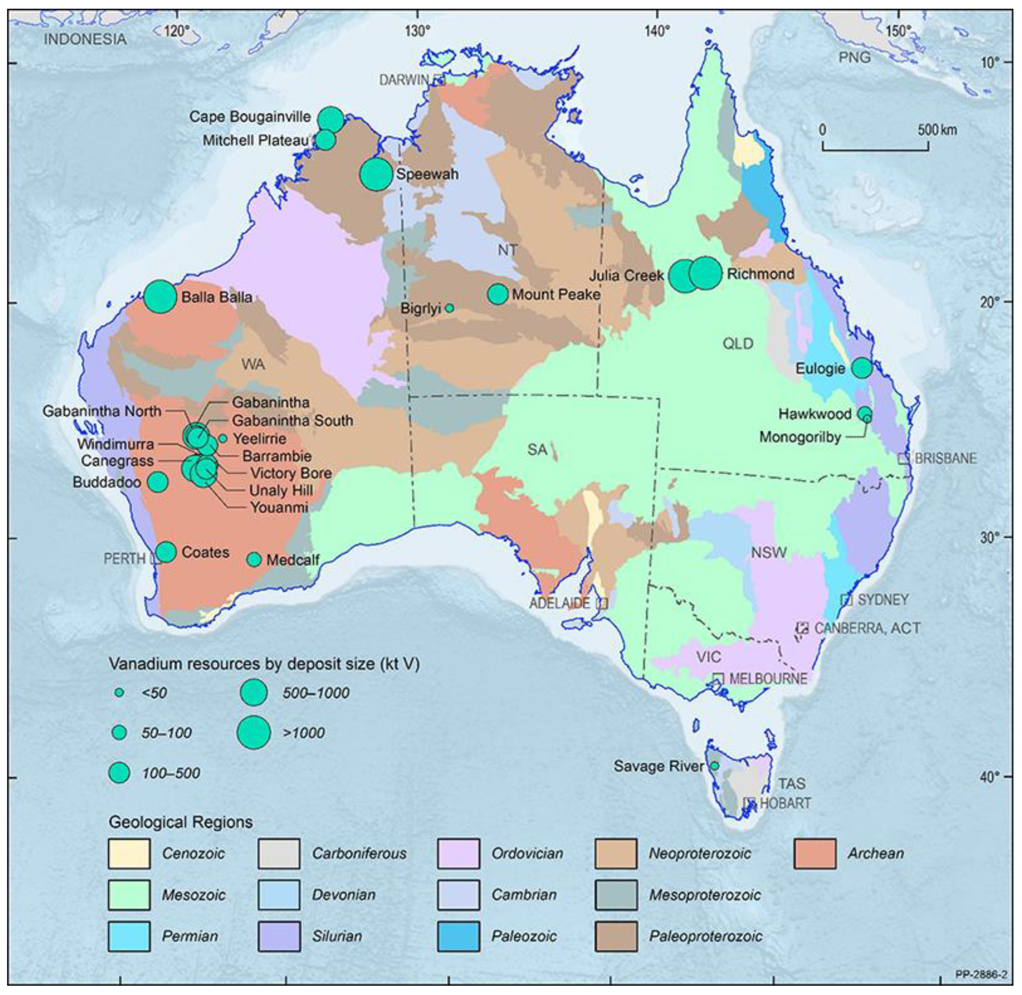
| Project | Organisation | Resource Type | Resource Output | Location |
|---|---|---|---|---|
| Mounte Peak | Tivan resources | VTM | VTMOC | Northern Territory |
| Vecco V + HPA project | Vecco group | SHV | BS-HVOO | Queensland |
| Saint Elmo | Mulitcom Resources Ltd. | SHV | CO | Queensland |
| Julia Creek project | Qem Ltd. | SHV | VBOS | Queensland |
| Toolebuc project | Toulebuc project | SHV | BS-HVOO | Queensland |
| The Richmond-Julia creek project | Richmond Vanadium Technology | SHV | BS-HVOO | Queensland |
| Speewah | Tivan Resources | VTM | VTMOC | Western Australia |
| Coates Project | Australian Vanadium limited | VTM | VTMOC | Western Australia |
| Buddadoo | Czr resources | VTM | VTMOC | Western Australia |
| Canegrass | Flinders mine Ltd. | VTM | VTMOC | Western Australia |
| Vindimurra project | Atlantic Ltd. | VTM | VTMOC | Western Australia |
| Younami-V-Oxide | Venus metals corporation Ltd. | VTM | VTMOC | Western Australia |
| Victory Bore and Unaly hill projects | Surefire Resources NI | VTM | VTMOC | Western Australia |
| Barrambie | Neometals Ltd. | VTM | VTMOC | Western Australia |
| Gabanitha-Murchison Technology metals project | VTM | VTMOC | Western Australia | |
| Yarrabubba-Murchison Technology metals project | Technology metals Australia Ltd. | VTM | VTMOC | Western Australia |
| Australian Vanadium Project | Australian Vanadium Ltd. | VTM | VTMOC | Western Australia |
| Nowthanna Hill | Australian Vanadium Ltd. | SHV | CO | Western Australia |
| Balla Balla | Forge metals Ltd. | VTM | VTMOC | Western Australia |
Disclaimer/Publisher’s Note: The statements, opinions and data contained in all publications are solely those of the individual author(s) and contributor(s) and not of MDPI and/or the editor(s). MDPI and/or the editor(s) disclaim responsibility for any injury to people or property resulting from any ideas, methods, instructions or products referred to in the content. |
© 2025 by the authors. Licensee MDPI, Basel, Switzerland. This article is an open access article distributed under the terms and conditions of the Creative Commons Attribution (CC BY) license (https://creativecommons.org/licenses/by/4.0/).
Share and Cite
Issa, T.B.; Van Yken, J.; Singh, P.; Nikoloski, A.N. Advancements and Applications of Redox Flow Batteries in Australia. Batteries 2025, 11, 78. https://doi.org/10.3390/batteries11020078
Issa TB, Van Yken J, Singh P, Nikoloski AN. Advancements and Applications of Redox Flow Batteries in Australia. Batteries. 2025; 11(2):78. https://doi.org/10.3390/batteries11020078
Chicago/Turabian StyleIssa, Touma B., Jonovan Van Yken, Pritam Singh, and Aleksandar N. Nikoloski. 2025. "Advancements and Applications of Redox Flow Batteries in Australia" Batteries 11, no. 2: 78. https://doi.org/10.3390/batteries11020078
APA StyleIssa, T. B., Van Yken, J., Singh, P., & Nikoloski, A. N. (2025). Advancements and Applications of Redox Flow Batteries in Australia. Batteries, 11(2), 78. https://doi.org/10.3390/batteries11020078