Article

Carbon-Coated CF-Si/Al Anodes for Improved Lithium-Ion Battery Performance

1
College of Chemical Engineering, Zhejiang University of Technology, Hangzhou 310014, China
2
Zhejiang Key Laboratory of Data-Driven High-Safety Energy Materials and Applications, Ningbo Key Laboratory of Special Energy Materials and Chemistry, Ningbo Institute of Materials Technology and Engineering, Chinese Academy of Sciences, Ningbo 315201, China
3
Ningbo Guangxin Nanomaterials Co., Ltd., Ningbo 315000, China
*
Authors to whom correspondence should be addressed.
Batteries 2025, 11(3), 114; https://doi.org/10.3390/batteries11030114
Submission received: 11 February 2025 / Revised: 4 March 2025 / Accepted: 14 March 2025 / Published: 18 March 2025
(This article belongs to the Special Issue Two-Dimensional Materials for Battery Applications)

Abstract

:
Despite their high specific capacity, magnetron-sputtered Si/Al thin films face rapid capacity decay due to stress-induced cracking, delamination, and detrimental electrolyte reactions. This study introduces a carbon-coated composite anode that overcomes these limitations, delivering superior reversible capacity, exceptional rate capability, and stable cycling performance. An electrochemical evaluation reveals that the CF-Si/Al@C-500-1h composite exhibits marked enhancements in capacity retention (43.5% after 100 cycles at 0.6 A·g−1) and rate capability, maintaining 579.1 mAh·g−1 at 3 A·g−1 (1 C). The carbon layer enhances electrical conductivity, buffers volume expansion during lithiation/delithiation, and suppresses silicon aggregation and electrolyte side reactions. Coupled with an aluminum framework, this architecture ensures robust structural integrity and efficient lithium-ion transport. These advancements position CF-Si/Al@C-500-1h as a promising anode material for next-generation lithium-ion batteries, while insights into scalable fabrication and carbon integration strategies pave the way for practical applications.

1. Introduction

Lithium-ion batteries (LIBs), as a pivotal energy storage technology, are integral to a wide range of applications, including electric vehicles and portable electronics. With the ongoing expansion of the new energy sector, there is a growing demand for LIBs that offer enhanced stability, high capacity, superior performance, safety, and environmental sustainability [1]. Conventional LIB anodes are primarily composed of graphite, which has a specific capacity of 372 mAh·g−1 [2]. Although graphite anodes offer excellent electrochemical performance and cycling stability, their relatively low theoretical capacity limits the potential of LIBs for high-energy-density applications. Therefore, the development of anode materials with higher specific capacities is crucial for advancing LIBs technology [3].
Silicon is considered one of the most promising anode materials for lithium-ion batteries, offering an exceptionally high theoretical specific capacity (4200 mAh·g−1), a low lithium insertion potential, and abundant natural availability [4,5,6,7]. However, silicon’s large volume expansion during lithiation (up to 300%) and its poor electrical conductivity (10−5–10−3 S·cm−1) lead to significant fracture and pulverization. Additionally, the lack of electrical conductivity and slow charge transfer kinetics, due to poor ion diffusion, result in low Coulombic efficiency, severely compromising cycling stability and capacity retention, which limits its practical application [8,9,10,11,12]. Therefore, research on silicon-based anode materials has primarily focused on addressing the issues of capacity degradation and stability during cycling, as well as the low Coulombic efficiency observed in the initial cycles. Solving these challenges is crucial for developing high-performance lithium-ion battery anodes [13].
To address the volume expansion issue of silicon anodes, researchers have explored and developed various silicon-based structures, including silicon nanotubes, nanowires, nanoparticles, and pomegranate-like nanostructures [14,15,16]. Although these nanostructures enhance the cycling performance of silicon anodes to some extent, their complex and costly synthesis processes hinder their scalability for commercial applications [7,17]. In contrast, thin-film silicon anodes have emerged as a popular research topic due to their simple fabrication process and stable performance [18].
Aluminum is known for its high electrical conductivity, a theoretical capacity of 993 mAh·g−1, and being the most abundant metallic element in the Earth’s crust, with a low density of 5 g·cm−3 [11,17]. According to the Si-Al phase diagram, magnetron sputtering plasma co-deposition at temperatures ranging from 300 to 577 °C results in uniform Si/Al thin films. The different lithiation potentials of Si and Al allow the volume of the electrodes to gradually change, while Al enhances the overall electrical conductivity of the thin film and effectively buffers the volume expansion during cycling, ensuring stable cycling and improved rate performance [19,20]. However, higher aluminum content tends to make the film more crystalline, so controlling the Al content within a lower range can result in amorphous or microcrystalline films [21,22]. Additionally, the carbon layer acts as a buffer, enhancing mechanical stability, preventing the active material from pulverizing, and reducing side reactions and electrolyte decomposition [23,24,25]. Carbon layers prepared by chemical vapor deposition (CVD) feature higher sp2 hybridization and fewer defects compared to those made by Physical Vapor Deposition (PVD), enabling the production of highly graphitized carbon layers [26].
In this paper, porous Si/Al thin films were fabricated by co-sputtering using a copper foam substrate as the current collector. The observed deviation in cyclic stability was attributed to internal stresses within the sputter-deposited films and the interfacial bonding. Additionally, the cracking of the thin-film material led to irreversible redox reactions between the electrode and the electrolyte, as well as the repeated regeneration of the solid electrolyte interphase (SEI) film [5,27]. To enhance the electrochemical performance of CF-Si/Al composites, a two-step modification strategy was implemented: first, the material underwent a thermal annealing treatment, followed by the deposition of a uniform carbon coating on the thin film surface through CVD. The electrochemical characterization revealed that the CF-Si/Al@C-500-1h composites showed significant improvement in both capacity retention and cycling stability, demonstrating an enhanced long-term electrochemical performance compared to the unmodified counterparts.

2. Materials and Methods

2.1. Materials and Equipment

The materials and equipment used in this study include the following: high-purity aluminum target (Zhongnuo New Material Technology Co., Ltd., Beijing, China); polycrystalline silicon target (Heqi Target Technology Co., Ltd., Zhangzhou, China); porous copper foam (Willtek Photoelectric Materials Co., Ltd., Suzhou, China); and a dual-chamber magnetron sputtering system (Keyou Vacuum Technology Co., Ltd., Shenyang, China). A dual temperature zone tube furnace (Boyuntong Instrument Technology Co., Ltd., Nanjing, China) was also used for carbon coating processes.

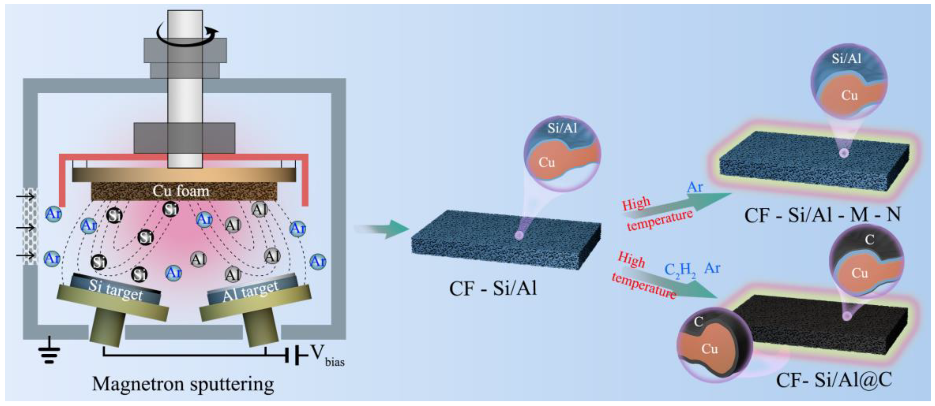
2.2. Preparation of CF-Si/Al Materials

Porous copper foam was punched into wafers with a diameter of 14 mm to serve as deposition substrates. The mass of the substrates was measured, and the active material load was calculated as the weight difference of the copper foam (CF) before and after deposition, divided by the deposition area. Glass and silicon wafers were also placed during deposition for measuring XRD patterns and film thickness. The Si/Al thin-film anode was synthesized on the copper foam substrate using medium-frequency magnetron sputtering with Si and Al targets. The deposition power of the Si target was set to 400 W, and the Al target to 25 W. The preparation process is illustrated in Figure 1. During sputtering, the target-to-substrate distance was maintained at 90 mm, and the substrate temperature was kept at 350 °C in an argon atmosphere. The chamber pressure during deposition was held at 0.5 Pa. Before deposition, the Si target was pre-sputtered using a medium-frequency power supply, and the Al target was pre-sputtered using a Direct Current (DC) power supply for 90 min. The resulting sample was labeled as CF-Si/Al. Under identical process parameters, pure Si films were also prepared for comparison and labeled as CF-Si. The thickness of all films was controlled between 1.5 and 2.5 μm.

2.3. Preparation of CF-Si/Al-M-N and CF-Si/Al@C-M-N Materials

The CF-Si/Al samples were annealed in an argon atmosphere using a tube furnace and labeled as CF-Si/Al-M-N (where M and N denote temperature and duration, respectively). To further enhance cycling stability, the CF-Si/Al samples were subjected to chemical vapor deposition (CVD) in an argon and acetylene atmosphere to deposit a carbon layer. These samples were labeled as CF-Si/Al@C-M-N (Table S2).

2.4. Material Characterization

The crystalline phase composition of CF-Si, CF-Si/Al, CF-Si/Al-M-N, and CF-Si/Al@C-M-N composites was analyzed using X-ray diffractometry (XRD, D8 ADVANCE, Bruker, Bremen, Germany) with Cu Kα radiation over a 2θ range of 5–80°. Structural characteristics and chemical bonding information were obtained through Raman spectroscopy (Raman spectra, LabRAM HR Evolution, Horiba, Paris, France) employing a 532 nm excitation source. Morphological features and elemental distribution patterns were investigated using field emission scanning electron microscopy (SEM, 8230, Hitachi, Tokyo, Japan) equipped with energy-dispersive X-ray spectroscopy capabilities. X-ray photoelectron spectroscopy (XPS, AXIS SUPRA+, Shimadzu (China) Co., Ltd., Kyoto, Japan) was employed to determine the surface elemental species, chemical states, and concentrations of the thin-film material.

2.5. Electrochemical Measurements

Inside a glovebox brimming with argon atmosphere, the prepared samples were assembled into active electrodes, lithium metal was assembled into counter electrodes, the coin cell model was CR2032, the separator was glass microfiber filters (Whatman GF/D, Guangdong Canrd New Energy Technology Co., Ltd., Donguan, China), and the electrolyte solution(Duoduo Chemical Technology Co., Ltd., Suzhou, China) was 1 M lithium hexafluorophosphate (LiPF6) and 5 wt.% of fluor ethylidene carbonate (FEC, C3H3FO3) dissolved in a mixture of ethylidene carbonate (EC, C3H4O3) and diethyl carbonate (DEC, C5H10O3) electrolyte solution with a volume ratio of 1:1. Electrochemical measurements were performed using a LAND-CT2001C tester (Wuhan Land Electronics Co., Ltd., Wuhan, China) for Galvanostatic charge–discharge tests (GCD, 0.01–3.0 V, vs. Li/Li+) at 30 °C (1 C = 3000 mAh·g−1). Cyclic voltammetry (CV, 0.01–2.0 V, vs. Li/Li+) and Electrochemical impedance spectroscopy (EIS, 0.01–100 kHz) were performed using an electrochemical workstation (Bio-logic VMP 3e, Seyssinet-Pariset, Paris, France).

3. Results and Discussion

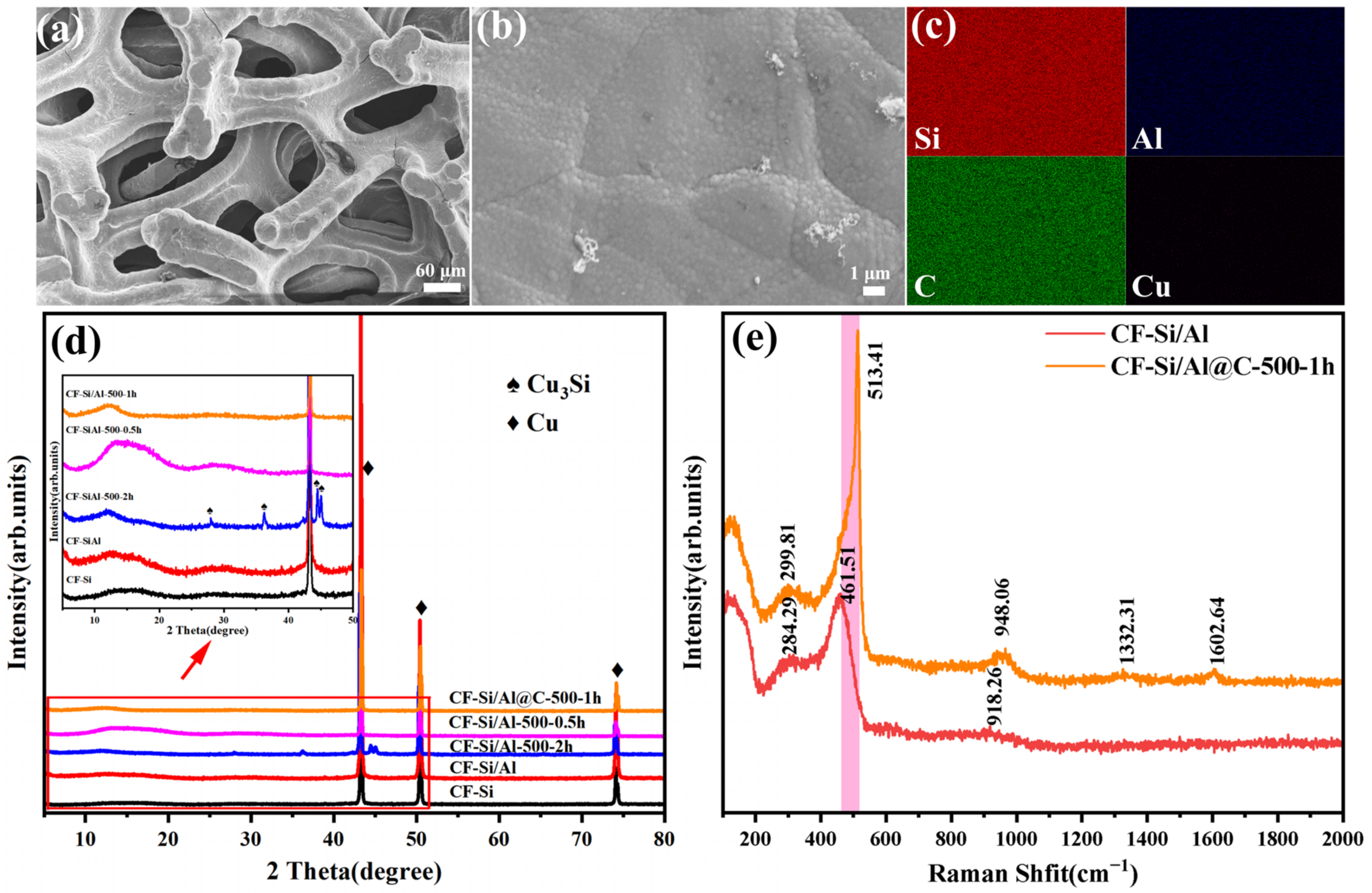
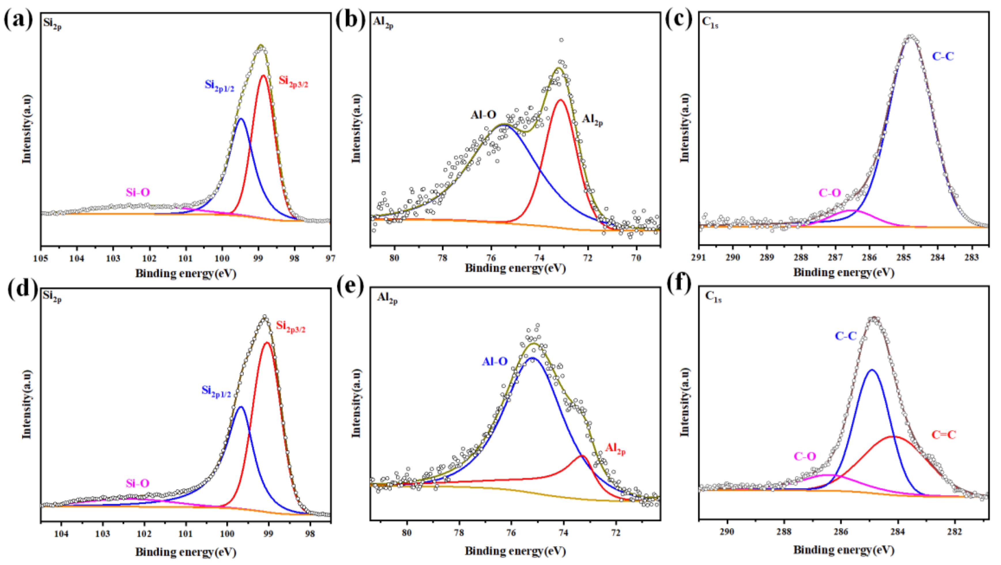
3.1. Material Morphology and Composition Analysis

In this work, we developed a simple, low-cost, and safe method for preparing binder-free composite Si-based anode materials. The preparation process (Figure 1) involved depositing Si and Al thin films onto the surface of Cu foam using magnetron sputtering. The resulting materials were characterized by XPS, revealing an atomic ratio of Si to Al (Table 1 and Table S3). This process involved the cracking of acetylene gas at high temperatures. The scanning image of the CF-Si/Al@C-500-1h sample shows a small amount of a carbon fiber-like structure, and the surface scanning energy spectrum reveals that the film is mainly composed of Si, C, and Al elements (Figure 2a–c). XRD analysis revealed that the diffraction peaks were primarily from the Cu substrate (crystal phase PDF#00-004-0836), with minimal peaks associated with the Al or Si-Al alloy phases. The weak diffraction peak centered at 28°, characteristic of crystalline Si (111), indicated that the films were predominantly amorphous in structure [1]. In contrast, the CF-Si/Al-M-N samples (M = 400, 500, 600; N = 2 h) were analyzed and compared to the characteristic diffraction peaks of Cu3Si (crystal phase PDF#00-051-0916). The results indicate that a high temperature and prolonged annealing time lead to copper diffusion from the copper foam substrate into the Si/Al film, resulting in the formation of lithium-active Cu3Si, according to the reaction (Figure S1a,b): Si + 3Cu → Cu3Si.
This process enhances both the electrical conductivity and the structural stability of the film [28]. Controlling the temperature at 500 °C and shortening the annealing duration can reduce the side reactions (Figure 2d). In the spectral range of 100–3000 cm−1, the main features of the spectrum include a low-intensity broadband centered around 461.51 cm−1 (unannealed films) and a very weak peak at approximately 513.41 cm−1 (annealed films). The former corresponds to the amorphous part of the film, while the latter corresponds to the crystalline part. Additionally, the broad bands at 299.81 cm−1 and 948.06 cm−1 are attributed to the scattering of the transverse-acoustic (TA) and optical-phonon (OP) modes of Si, respectively [29,30]. The two absorption bands located near 1332.31 cm−1 and 1602.64 cm−1 correspond to the sp3-hybridized carbon (D-band) and sp2-hybridized graphite domains (G-band), respectively [31,32]. The ID/IG ratio is 0.93, indicating a high degree of graphite in the carbon, which is beneficial for the film anode by enhancing its electrical conductivity [33,34]. Meanwhile, after the high-temperature treatment, the Raman peak width shifts slightly, indicating the release of residual stresses within the thin-film material [35]. In summary, it can be concluded that the deposited Si/Al thin films are predominantly amorphous, with a small fraction of polycrystalline structures. In the unannealed films, Si exists in an amorphous form, whereas the annealed films primarily exhibit an amorphous structure along with a nanocrystalline phase [36].
In order to further ascertain additional information regarding the surface chemical composition of the material surface, comparative XPS analyses were performed on CF-Si/Al and CF-Si/Al@C-500-1h samples, with a polluting carbon reference calibrated at 284.8 eV. The Si2p spectrum reveals two characteristic Si-Si bonding peaks at 98.86 eV and 99.48 eV, accompanied by a Si-O bonding peak at 102.35 eV. The electronegativity of Al is lower than that of Si. In alloys, Al tends to transfer some of its electrons to Si, resulting in a slight increase in the electron density around the Si. This would weaken the effective nuclear charge on Si’s inner electrons, thereby reducing their binding energy [36]. For the Al2p region, characteristic peaks at 73.13 eV and 75.48 eV correspond to the Si-Al and Al-O bonds, respectively [37]. Notably in the C1s spectrum, CF-Si/Al@C-500-1h exhibits three distinct components: the main peak at 284.79 eV (C-C), 286.52 eV (C-O), and a newly emerged peak at 284.11 eV, which is attributable to the C=C bonds [38]. This emergence of carbon signatures, combined with the attenuation of the substrate signals, conclusively demonstrates the effective encapsulation of the membrane surface by a carbonaceous layer through the CVD treatment (Figure 3a–f, Table S3).

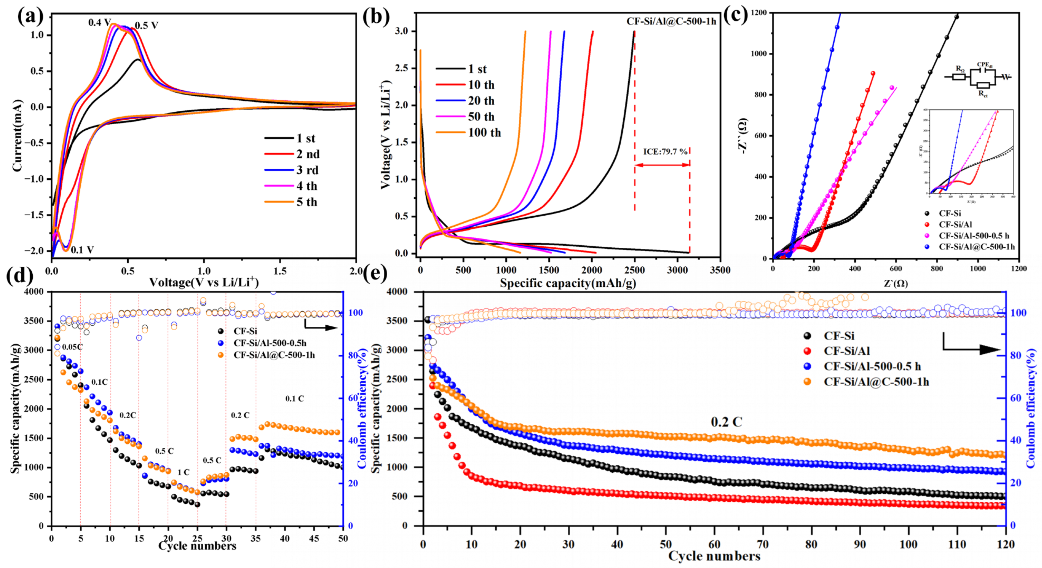
3.2. Electrochemical Performance Analysis

A uniformly distributed carbon layer on the surface not only provides effective protection for the Si/Al films but also serves as a robust conductive network during lithium storage. The lithiation/delithiation performance of the composites is critical and was investigated through CV and GCD measurements of the lithium-ion storage. As shown in Figure 4a, the lithiation and delithiation behaviors of the CF-Si/Al@C-500-1h electrode were tested in a CR2032 coin cell with the voltage range of 0.01–2.0 V and the scan rate of 0.1 mV·s−1. The reduction peaks in the first and second cycles were minimal, which could be attributed to electrode activation, as well as the lithiation of the amorphous silicon and the formation of LixSi. However, in the third cycle, a reduction peak appeared around 0.1 V. The dual oxidation signals observed at approximately 0.32 V and 0.55 V correspond to the amorphous silicon generation and lithium-ion extraction from LixSi alloy, respectively [39]. The progressive intensification and peak broadening during cycling compared to initial cycles suggest electrode activation kinetics involving structural reorganization processes [40]. In contrast, the CF-Si/Al@C-500-1h electrode has a smaller ∆U of 0.94 V, reflecting the beneficial role of aluminum (Al) as well as carbon in mitigating polarization (Figure S7).
As shown in Figure S5, the CV curves of CF-Si and CF-Si/Al-500-0.5 h exhibit similar behavior, with redox peaks that align with previous reports, resembling the typical features of Si. The voltage-to-mass ratio capacity distributions of the CF-Si/Al@C-500-1h electrode for the 1st, 10th, 20th, 50th, and 100th cycles at a current density of 0.2 C (600 mA·g−1) within the voltage window of 0.01–3 V are shown in Figure 4b. Additionally, the initial discharge capacity of CF-Si/Al@C-500-1h was 3128.2 mAh·g−1, with a charge capacity of 2493.0 mAh·g−1, resulting in an initial coulombic efficiency (ICE) of 79.7%. The capacity retention rates at the 10th, 20th, 50th, and 100th cycles were measured at 64.3%, 53.9%, 48.7%, and 43.5%, respectively, highlighting the exceptional capacity reversibility of the CF-Si/Al@C-500-1h anode. The main charging and discharging voltage platforms of CF-Si and CF-Si/Al are like those of CF-Si/Al@C-500-1h, as shown in Figure S5i–l. For comparison, the discharge capacities of CF-Si, CF-Si/Al, and CF-Si/Al-500-0.5 h were 3520.9, 3156.7, and 3213.3 mAh·g−1, corresponding to the ICE of 86.2%, 82.5%, and 83.8%, respectively. The capacity retention at the 50th cycle for CF-Si, CF-Si/Al, and CF-Si/Al-500-0.5 h was 23.9%, 16.2%, and 37.7%, respectively. The capacity retention of CF-Si/Al increased by approximately 200% after the deposition of the carbon layer on CF-Si/Al, clearly demonstrating the enhanced cycling stability (Table S4).
Figure 4c presents the distinct EIS for CF-Si, CF-Si/Al, CF-Si/Al-500-0.5h, and CF-Si/Al@C-500-1h, illustrating common patterns found in lithium-ion batteries. In the high-frequency region, a semicircular arc is observed, with the diameter corresponding to the charge transfer process. Meanwhile, the low-frequency region features a diagonal line indicative of Warburg impedance, which is associated with the Li+ diffusion coefficient within the electrode. Decrease in ICE and specific capacity due to long annealing times, side reactions (e.g., formation of Cu3Si), and factors related to the gas tightness of the tube furnace equipment (adsorption of small amounts of oxygen to form Al2O3, CuO, Cu2O) [41,42]. The CF-Si/Al@C-500-1h sample exhibits a charge transfer resistance (Rct) of 45.57 Ω, significantly lower than that of the CF-Si/Al sample (98.23 Ω). This notable reduction in Rct further confirms the substantial enhancement in electronic conductivity achieved through carbon coating. These results suggest that the introduction of the carbon layer markedly enhances the electronic conductivity of the Si/Al composite [43]. Overall, these findings highlight that the carbon layer effectively accelerates both electron and ion transfer, leading to a significant improvement in the lithiation/delithiation rate (Table 2, Figure 4b).
Figure 4d illustrates that the electrode’s capacity decreases as the current density increases from 0.05 C to 1 C. This trend suggests that higher charge/discharge current densities can lead to significant damage to the electrode structure, resulting in a marked decline in its electrochemical performance. After completing 35 charge–discharge cycles, when the current density was restored to 0.1 C, the CF-Si/Al@C-500-1h electrode exhibited a remarkable capacity recovery, with its specific capacity increasing to 1684.2 mAh·g−1. This capacity rebound phenomenon clearly indicates that the electrode material maintains excellent structural integrity and demonstrates superior tolerance to high-current cycling conditions. Moreover, the electrode’s ability to recover its capacity after rigorous cycling not only confirms its structural stability but also highlights its exceptional rate capability, suggesting that the material can withstand various current densities without undergoing significant electrochemical degradation.
To further compare the cycling stability of the CF-Si, CF-Si/Al, CF-Si/Al-M-N, and CF-Si/Al@C-M-N anode materials to demonstrate the effect of the carbon layer on the electrochemical performance, constant current charge/discharge tests were performed to evaluate their cycle life in the range of 0.01–3 V at a current density of 0.2 C (0.6 A·g−1) (Figure 4e). The CF-Si/Al@C-500-1h electrode demonstrated a reversible capacity of 1224.5 mAh·g−1 after 100 cycles, corresponding to a capacity retention of 43.5%. In contrast, the CF-Si/Al-500 electrode exhibited an initial discharge capacity of 3156.7 mAh·g−1, which rapidly declined to 341.8 mAh·g−1 by the 100th cycle, resulting in a significantly lower capacity retention of only 11.7%. Similarly, the CF-Si/Al electrode showed an initial discharge capacity of 3213.3 mAh·g−1, but its capacity sharply decreased to 924.5 mAh·g−1 after 100 cycles, achieving a capacity retention of 37.7%. The enhanced cycling stability is primarily attributed to the carbon coating, which effectively accommodates substantial volume changes. Analogous to a thicker cushion absorbing greater mechanical stress, the carbon layer mitigates structural degradation by shielding the Si from direct electrolyte exposure, thereby significantly minimizing irreversible capacity loss over repeated cycles.

3.3. Electrochemical Kinetics

To investigate the lithium-ion transport process and electrode kinetics, CV curves were recorded at scan rates of 0.1, 0.2, 0.5, 1.0, and 2.0 mV·s−1, as shown in Figure 5a. The variation in the CV curves with the increasing scan rate is clearly observed. Notably, the redox peaks shift to a higher potential as the scan rate increases; a behavior closely linked to the kinetics of lithium insertion and extraction at the electrode–electrolyte interface, as well as the lithium diffusion rate. Equations (1) and (2) summarize the relationship between the peak current (ip) and the scan rate (v). The capacity of the lithium-ion battery is derived from both the capacitive effect of the electrodes and the diffusion of lithium-ion during the charging process [44,45]. The pseudocapacitance contribution is characterized by analyzing the CV data using the following equations [46]:
ip = avb
Log(ip) = blog(v) + log(a)
The parameter b represents the slope derived from plotting log(ip) against log(v), where ip denotes the maximum current measured at varying voltages and v indicates the scanning rate. For the CF-Si/Al@C-500-1h composite material, the calculated b-values corresponding to cathodic and anodic processes were determined to be 0.37 and 0.39, respectively (Figure 5b), with both values falling below the characteristic 0.5 threshold. This indicates that the charge storage mechanism is predominantly diffusion controlled [3]. The contributions of pseudocapacitive effects and diffusion to the capacity of LIBs can be assessed by calculating the corresponding integrals and performing nonlinear fitting on the CV curves. The ratio of capacitive to diffusion contributions is determined from the area under the fitted curve, with each specific voltage corresponding to a fitted k1 value [46,47].
i = k1v + k2v0.5
In Equation (3), i denotes the peak current at different voltages, v represents the scan rate, k1v describes the capacitive contribution to the charging current, and k2v0.5 characterizes the diffusional contribution. By examining the CV curves at varying scan rates, the coefficients k1 and k2 can be determined as functions of V. These coefficients enable the quantification of the capacitive and diffusional contributions to the total capacity of the lithium-ion battery through the integration of k1v and k2v0.5, respectively, across the voltage range. By dividing the area under the fitted curve by the total area under the CV curve, the capacitive contribution rate at a given scan rate can be calculated, and similar calculations can be performed for other scan rates [48]. However, across all investigated scan rates, the capacitive contribution of the CF-Si/Al@C-500-1h electrode demonstrates superior performance, consistently surpassing those of the CF-Si, CF-Si/Al and CF-SiAl-500-0.5h electrodes. This enhanced capacitive behavior is particularly significant as it facilitates more efficient ion storage kinetics, enabling both rapid and reversible ion insertion/extraction processes, which are crucial for high-performance electrochemical energy storage applications [49]. As the scan rate and cycle number increase, the pseudocapacitive contribution also grows, and the superior rate performance can be attributed to the enhanced capacitive effects in CF-Si/Al@C-500-1h (Figure 5c,d and Figure S6a–d).
As illustrated in Figure S5a–h, the reversibility of electrochemical reactions occurring on the electrode surface can be evaluated through the analysis of the peak heights and symmetry in the oxidation and reduction waves observed in both the cathodic and anodic directions of the cyclic voltammograms. The electrochemical behavior of CF-Si and CF-Si/Al electrodes demonstrates distinct characteristics, manifested by varying peak heights and asymmetric wave patterns. Notably, with increasing scan rates, the oxidation peak of these materials fails to exhibit the expected positive potential shift and instead shows a decreasing trend, suggesting a relatively higher degree of electrochemical irreversibility compared to the CF-Si/Al-500-0.5 h and CF-Si/Al@C-500-1h electrodes. Furthermore, comparative analysis reveals that the oxidation peaks of the CF-Si and CF-Si/Al electrodes consistently maintain higher intensities than those observed in CF-Si/Al@C-500-1h electrodes, indicating different electrochemical kinetics among these materials [50,51].

3.4. Changes in Film Surface Morphology Before and After Cycling

To further illustrate the reasons behind the superior performance of CF-Si/Al@C-500-1h compared to the other films, the SEM images in Figure 6a–f demonstrate the surface morphology and thickness changes of the three electrode materials before and after cycling. The observed filamentous substance is the residual glass microfibers remaining on the surface of the electrode. Due to the significant volume expansion and contraction caused by lithium-ion insertion and extraction, CF-Si developed numerous cracks, resulting in a surface that resembled dry, cracked land. In contrast, CF-Si/Al exhibited less expansion, owing to the involvement of Al, but still showed cracks and significant detachment. The complex-like substances observed in the SEM images may be due to the reaction between the electrolyte and the electrode material. The annealed material displayed poor film integrity, although the shedding was reduced. However, the cracking in the films of CF-Si/Al@C-500-1h was much less pronounced compared to CF-Si and CF-Si/Al, likely due to the addition of the carbon layer. As illustrated in Figure S8, the CF-Si electrode exhibited significant cracks and structural collapse after cycling, consistent with the intrinsic volume effect of silicon. The CF-Si/Al electrode showed mitigated expansion, indicating that the introduction of Al reduces the expansion of the thin-film electrode during cycling. The CF-Si/Al@C-500-1h electrode displayed optimal structural stability, where the carbon layer effectively buffered volume variation while maintaining electrode integrity [52]. While cracking was still observed in CF-Si/Al@C-500-1h, the membrane structure remained relatively intact, with much less detachment than in CF-Si and CF-Si/Al.
Following the principle that greater cracking leads to higher resistance, the integrity of the membrane anode can be further verified by measuring the change in electrode resistance using EIS before and after cycling. The integrity of the films is confirmed by the resistance change measured before and after cycling. Figure 7a,b show the corresponding EIS curves of the original and cycled films. The charge transfer resistance (Rct) of the CF-Si/Al composite exhibited a notable increase after cycling compared to its pre-cycled state, a phenomenon that correlates well with the morphological evolution observed through scanning electron microscopy (SEM) characterization. During the cycling process of CF-Si/Al, due to side reactions (such as passivation, corrosion, etc.) between the electrode material and the electrolyte, a semicircle phenomenon appears in the low-frequency region [20]. Specifically, we have used the relationship between the real part of the impedance (Zre) and the square root of the angular frequency (ω−1/2) in the low-frequency region, as described by the following equation [53]:
ω = 2πf
Zre = Rct + RΩ + σω−1/2
where Rct is the charge transfer resistance, RΩ is the electrolyte resistance, and σ is the Warburg coefficient (Figure 7c,d, Table 2). The Li⁺ diffusion coefficient (DLi+) can then be calculated using the following equation [53]:
D L i + = R 2 T 2 2 A 2 n 4 F 4 C 2 σ 2
where R is the gas constant, T is the absolute temperature, A is the electrode area, n is the number of electrons transferred, F is the Faraday constant, and C is the concentration of Li+ in the electrode. The calculated lithium-ion diffusion coefficient of the carbon-coated sample of CF-Si/Al@C-500-1h (2.01 × 10⁻¹⁰ cm2/s) was significantly higher than that of CF-Si/Al (8.51 × 10⁻¹¹ cm2/s), demonstrating that the carbon layer enhances lithium-ion diffusion (Table 2) [50].
The experimental results demonstrate that the CF-Si/Al@C-500-1h anode exhibits excellent electrochemical properties, including high reversible capacity, good rate capability, and long, stable cycling life. The carbon layer and Al significantly improve the electrical conductivity of the CF-Si/Al@C-500-1h anode. Additionally, the carbon layer provides ample buffer space for the Si/Al film, preventing side reactions between the film material and the electrolyte. Notably, the carbon coating effectively prevents Si aggregation during the lithiation/delithiation process and reduces the fragmentation of Si into small particles during repeated volume expansion and contraction.

4. Conclusions

In summary, the CF-Si/Al@C-500-1h anode has demonstrated a remarkable electrochemical performance, characterized by high reversible capacity, excellent rate capability, and enhanced cycling stability. The strategic integration of a carbon layer and aluminum significantly improves the electrical conductivity of the anode, facilitating efficient lithium-ion transport during charge and discharge processes. The carbon layer serves a dual purpose: it provides structural integrity by buffering the volume changes associated with lithium-ion insertion and extraction, while also preventing side reactions with the electrolyte which can degrade performance over time. Additionally, the carbon coating effectively mitigates the aggregation of silicon particles during the lithiation and delithiation cycles, which is critical for maintaining the material’s integrity and performance across multiple cycles. This comprehensive approach not only highlights the potential of CF-Si/Al@C-500-1h as a superior anode material but also paves the way for further exploration and optimization of silicon-based composites for next-generation lithium-ion batteries. Future research should focus on optimizing the manufacturing process and exploring different carbon materials to enhance the overall performance and scalability of these anodes.

Supplementary Materials

The following supporting information can be downloaded at https://www.mdpi.com/article/10.3390/batteries11030114/s1. Figure S1. (a,b) XRD patterns of CF-Si, CF-Si/Al and CF-Si/Al-M-N (c,d) XRD patterns of CF-Si/Al and CF-Si/Al@C-M-N; Figure S2. (a,b) Raman spectra of CF-Si/Al and CF-Si/Al@C-M-N; Figure S3. (a–f) SEM patterns of CF-Si/Al and CF-Si/Al@C-M-N; Figure S4. (a) Rate capabilities of CF-Si, CF-Si/Al, and CF-Si/Al-M-N at 0.05 C–0.1 C–0.2 C–0.5 C–1 C current density. (b) Cycling performance of CF-Si and CF-Si/Al-M-N at current density of 0.2 C. (c) Rate capabilities of CF-Si, CF-Si/Al, and CF-Si/Al@C-M-N at 0.05 C–0.1 C–0.2 C–0.5 C–1 C current density. (d) Cycling performance of CF-Si, CF-Si/Al, and CF-Si/Al@C-M-N at current density of 0.2 C. Figure S5. (a–d) CV curves of CF-Si, CF-Si/Al, CF-Si/Al-500-0.5h and CF-Si/Al@C-500-2h at a scanning rate of 0.1 mV·s−1. (e–h) CV curves of CF-Si, CF-Si/Al, CF-Si/Al-500-0.5h and CF-Si/Al@C-500-2h at different potential scanning rates. (i–l) Galvanostatic charge–discharge curves of CF-Si, CF-Si/Al, CF-Si/Al-500-0.5 h and CF-Si/Al@C-500-2h at a specific current of 0.2 C current density. Figure S6. (a,b) The pseudocapacitive contribution proportion of at a scan rate of 0.1-0.2-0.5-1.0 mV·s−1. Figure S7. (a,b) The dQ/dV curves and the corresponding potential differences (∆U) between the oxidation and reduction peaks. Figure S8. (a–f) SEM cross-sectional images of CF-Si, CF-Si/Al, and CF-Si/Al@C-500-1h before cycling and after cycling. Table S1. Calculation of the mass of the active substance. Table S2. Preparation parameters and raman peak fitting of CF-Si/Al@C-M-N. Table S3. C1s, Si2p, Al2p curve-fitting parameters. Table S4. ICE and capacity retention for CF-Si, CF-Si/Al, CF-Si/Al-M-N and CF-Si/Al@C-M-N; Table S5. Electrochemical performance of other literature [7,42,54,55,56,57,58,59,60].

Author Contributions

Conceptualization, K.L. and P.L.; methodology, L.Z.; software, L.Z.; validation, K.L., P.L. and S.G; formal analysis, K.L.; investigation, L.Z.; resources, K.L.; data curation, L.Z.; writing—original draft preparation, L.Z.; writing—review and editing, K.L.; visualization, M.O.; supervision, K.L.; project administration, K.L. and S.G.; funding acquisition, K.L. and M.O. All authors have read and agreed to the published version of the manuscript.

Funding

The authors gratefully thank the support from National Natural Science Foundation of China (52073257), the Key Research, and the Development Program of Zhejiang Province (2021C01080).

Data Availability Statement

The authors confirm that the data supporting the findings of this study are available within the article.

Conflicts of Interest

Author Shujuan Gao was employed by the company Ningbo Guangxin Nanomaterials Co., Ltd. The remaining authors declare that the research was conducted in the absence of any commercial or financial relationships that could be construed as a potential conflict of interest.

References

  1. Li, H.; Li, H.; Lai, Y.; Yang, Z.; Yang, Q.; Liu, Y.; Zheng, Z.; Liu, Y.; Sun, Y.; Zhong, B.; et al. Revisiting the Preparation Progress of Nano-structured Si Anodes toward Industrial Application from the Perspective of Cost and Scalability. Adv. Energy Mater. 2022, 12, 2102181. [Google Scholar] [CrossRef]
  2. Yang, X.; Kong, W.; Du, G.; Li, S.; Tang, Y.; Cao, J.; Lu, X.; Tan, R.; Qian, G. Synthesis of a Yolk-Shell Nanostructured Silicon-Based Anode for High-Performance Li-Ion Batteries. Batteries 2023, 9, 446. [Google Scholar] [CrossRef]
  3. Li, Y.; Li, Q.; Chai, J.; Wang, Y.; Du, J.; Chen, Z.; Rui, Y.; Jiang, L.; Tang, B. Si-Based Anode Lithium-Ion Batteries: A Comprehensive Review of Recent Progress. ACS Mater. Lett. 2023, 5, 2948–2970. [Google Scholar] [CrossRef]
  4. Yang, Q.; Wang, Z.; Xia, Y.; Wu, G.; Chen, C.; Wang, J.; Rao, P.; Dong, A. Facile Electrostatic Assembly of Si@MXene Superstructures for Enhanced Lithium-Ion Storage. J. Colloid Interface Sci. 2020, 580, 68–76. [Google Scholar] [CrossRef]
  5. Fang, Q.; Xu, S.; Sha, X.; Liu, D.; Zhang, X.; Li, W.; Weng, S.; Li, X.; Chen, L.; Li, H.; et al. Interfacial Degradation of Silicon Anodes in Pouch Cells. Energy Environ. Sci. 2024, 17, 6368–6376. [Google Scholar] [CrossRef]
  6. Kulova, T.L.; Mironenko, A.A.; Skundin, A.M.; Rudy, A.S.; Naumov, V.V.; Pukhov, D.E. Study of Silicon Composite for Negative Electrode of Lithium-Ion Battery. Int. J. Electrochem. Sci. 2016, 11, 1370–1381. [Google Scholar] [CrossRef]
  7. Cheng, Y.; Wei, K.; Yu, Z.; Fan, D.; Yan, D.L.; Pan, Z.; Tian, B. Ternary Si-SiO-Al Composite Films as High-Performance Anodes for Lithium-Ion Batteries. ACS Appl. Mater. Interfaces 2021, 13, 34447–34456. [Google Scholar] [CrossRef]
  8. Han, M.; Mu, Y.; Wei, L.; Zeng, L.; Zhao, T. Multilevel Carbon Architecture of Subnanoscopic Silicon for Fast-charging High-energy-density Lithiumion Batteries. Carbon Energy 2024, 6, e377. [Google Scholar] [CrossRef]
  9. Huo, H.; Janek, J. Silicon as Emerging Anode in Solid-State Batteries. ACS Energy Lett. 2022, 7, 4005–4016. [Google Scholar] [CrossRef]
  10. Keles, O.; Karahan, B.D.; Eryilmaz, L.; Amine, R.; Abouimrane, A.; Chen, Z.; Zuo, X.; Zhu, Z.; Al-Hallaj, S.; Amine, K. Superlattice-Structured Films by Magnetron Sputtering as New Era Electrodes for Advanced Lithium-Ion Batteries. Nano Energy 2020, 76, 105094. [Google Scholar] [CrossRef]
  11. Salah, M.; Hall, C.; Francis, C.; Rollo-Walker, G.; Fabretto, M. Binary Silicon-Based Thin-Film Anodes for Lithium-Ion Batteries: A Review. J. Power Sources 2022, 520, 230871. [Google Scholar] [CrossRef]
  12. Wang, H.; Man, H.; Yang, J.; Zang, J.; Che, R.; Wang, F.; Sun, D.; Fang, F. Self-adapting Electrochemical Grinding Strategy for Stable Silicon Anode. Adv. Funct. Mater. 2022, 32, 2109887. [Google Scholar] [CrossRef]
  13. Manthiram, A. An Outlook on Lithium-Ion Battery Technology. ACS Cent. Sci. 2017, 3, 1063–1069. [Google Scholar] [CrossRef] [PubMed]
  14. Tang, H.; Xu, Y.; Liu, L.; Zhao, D.; Zhang, Z.; Wu, Y.; Zhang, Y.; Liu, X.; Wang, Z. A Hollow Silicon Nanosphere/Carbon Nanotube Composite as an Anode Material for Lithium-Ion Batteries. Coatings 2022, 12, 1515. [Google Scholar] [CrossRef]
  15. Collins, G.A.; Kilian, S.; Geaney, H.; Ryan, K.M. A Nanowire Nest Structure Comprising Copper Silicide and Silicon Nanowires for Lithium-ion Battery Anodes with High Areal Loading. Small 2021, 17, 2102333. [Google Scholar] [CrossRef]
  16. Tang, W.; Guo, X.; Liu, X.; Chen, G.; Wang, H.; Zhang, N.; Wang, J.; Qiu, G.; Ma, R. Interconnected Silicon Nanoparticles Originated from Halloysite Nanotubes through the Magnesiothermic Reduction: A High-Performance Anode Material for Lithium-Ion Batteries. Appl. Clay Sci. 2018, 162, 499–506. [Google Scholar] [CrossRef]
  17. Wu, H.; Cui, Y. Designing Nanostructured Si Anodes for High Energy Lithium-Ion Batteries. Nano Today 2012, 7, 414–429. [Google Scholar] [CrossRef]
  18. Leung, O.M.; Gordon, L.W.; Messinger, R.J.; Prodromakis, T.; Wharton, J.A.; Ponce De León, C.; Schoetz, T. Solid Polymer Electrolytes with Enhanced Electrochemical Stability for High-capacity Aluminum Batteries. Adv. Energy Mater. 2024, 14, 2303285. [Google Scholar] [CrossRef]
  19. Aslanbas, Ö.; Durmus, Y.E.; Tempel, H.; Hausen, F.; Ein-Eli, Y.; Eichel, R.-A.; Kungl, H. Electrochemical Analysis and Mixed Potentials Theory of Ionic Liquid Based Metal–Air Batteries with Al/Si Alloy Anodes. Electrochim. Acta 2018, 276, 399–411. [Google Scholar] [CrossRef]
  20. Sun, B.; Xu, Y.; Yang, S.; Zhang, D.; Pei, C.; Ni, S. Al-Based Materials for Advanced Lithium Rechargeable Batteries: Recent Progress and Prospects. Mater. Chem. Front. 2023, 7, 2554–2569. [Google Scholar] [CrossRef]
  21. Fleischauer, M.D.; Obrovac, M.N.; Dahn, J.R. Al-Si Thin-Film Negative Electrodes for Li-Ion Batteries. J. Electrochem. Soc. 2008, 155, A851. [Google Scholar] [CrossRef]
  22. Johnson, B.C.; Stuiber, M.; Creedon, D.L.; Bose, M.; Berhane, A.; Willems Van Beveren, L.H.; Rubanov, S.; Cole, J.H.; Mourik, V.; Hamilton, A.R.; et al. Silicon-Aluminum Phase-Transformation-Induced Superconducting Rings. Nano Lett. 2023, 23, 17–24. [Google Scholar] [CrossRef] [PubMed]
  23. Reyes Jiménez, A.; Klöpsch, R.; Wagner, R.; Rodehorst, U.C.; Kolek, M.; Nölle, R.; Winter, M.; Placke, T. A Step toward High-Energy Silicon-Based Thin Film Lithium-Ion Batteries. ACS Nano 2017, 11, 4731–4744. [Google Scholar] [CrossRef] [PubMed]
  24. Wang, J.; Li, S.; Zhao, Y.; Shi, J.; Lv, L.; Wang, H.; Zhang, Z.; Feng, W. The Influence of Different Si: C Ratios on the Electrochemical Performance of Silicon/Carbon Layered Film Anodes for Lithium-Ion Batteries. RSC Adv. 2018, 8, 6660–6666. [Google Scholar] [CrossRef]
  25. Li, W.; Yang, R.; Wang, X.; Wang, T.; Zheng, J.; Li, X. Intercalated Si/C Films as the Anode for Li-Ion Batteries with near Theoretical Stable Capacity Prepared by Dual Plasma Deposition. J. Power Sources 2013, 221, 242–246. [Google Scholar] [CrossRef]
  26. Korzhenko, D.V.; Yurjev, Y.N.; Emlin, D.R.; Plotnikov, S.A.; Vladimirov, A.B.; Romanov, I.Y.; Loginov, B.A.; Loginov, A.B. Comparative Analysis of Properties of the Carbon-Based Coatings Obtained through Various PVD and CVD Deposition Methods. J. Phys. Conf. Ser. 2020, 1443, 12006. [Google Scholar] [CrossRef]
  27. Windischmann, H. Intrinsic Stress in Sputter-Deposited Thin Films. Crit. Rev. Solid State Mater. Sci. 1992, 17, 547–596. [Google Scholar] [CrossRef]
  28. Zhou, J.; Lin, N.; Han, Y.; Zhou, J.; Zhu, Y.; Du, J.; Qian, Y. Cu3Si@Si Core-Shell Nanoparticles Synthesized Using a Solid-State Reaction and Their Performance as Anode Materials for Lithium-Ion Batteries. Nanoscale 2015, 7, 15075–15079. [Google Scholar] [CrossRef]
  29. Ruttert, M.; Siozios, V.; Winter, M.; Placke, T. Mechanochemical Synthesis of Fe-Si-Based Anode Materials for High-Energy Lithium Ion Full-Cells. ACS Appl. Energy Mater. 2020, 3, 743–758. [Google Scholar] [CrossRef]
  30. Chen, Z.; Hou, J.; Liu, Q.; Zhou, Q.; Liu, H.; Xu, C. Graphene Quantum Dots Modified Nanoporous SiAl Composite as an Advanced Anode for Lithium Storage. Electrochim. Acta 2019, 318, 228–235. [Google Scholar] [CrossRef]
  31. Liu, Y.; Xu, M.; Zhu, X.; Xie, M.; Su, Y.; Hu, N.; Yang, Z.; Zhang, Y. Synthesis of Carbon Nanotubes on Graphene Quantum Dot Surface by Catalyst Free Chemical Vapor Deposition. Carbon 2014, 68, 399–405. [Google Scholar] [CrossRef]
  32. Li, K.; Kang, Y.; Deng, C.; Wang, Y.; Ba, H.; An, Q.; Han, X.; Huang, S. S, Se-Codoped Dual Carbon Coating and Se Substitution in Co-Alkoxide-Derived CoS2 through SeS2 Triggered Selenization for High-Performance Sodium-Ion Batteries. Batteries 2025, 11, 28. [Google Scholar] [CrossRef]
  33. Brubaker, Z.E.; Langford, J.J.; Kapsimalis, R.J.; Niedziela, J.L. Quantitative Analysis of Raman Spectral Parameters for Carbon Fibers: Practical Considerations and Connection to Mechanical Properties. J. Mater. Sci. 2021, 56, 15087–15121. [Google Scholar] [CrossRef]
  34. Chen, W.; Li, D.; Tian, L.; Xiang, W.; Wang, T.; Hu, W.; Hu, Y.; Chen, S.; Chen, J.; Dai, Z. Synthesis of Graphene Quantum Dots from Natural Polymer Starch for Cell Imaging. Green Chem. 2018, 20, 4438–4442. [Google Scholar] [CrossRef]
  35. Sharma, M.; Rani, S.; Pathak, D.K.; Bhatia, R.; Kumar, R.; Sameera, I. Temperature Dependent Raman Modes of Reduced Graphene Oxide: Effect of Anharmonicity, Crystallite Size and Defects. Carbon 2021, 184, 437–444. [Google Scholar] [CrossRef]
  36. Yogi, P.; Tanwar, M.; Saxena, S.K.; Mishra, S.; Pathak, D.K.; Chaudhary, A.; Sagdeo, P.R.; Kumar, R. Quantifying the Short-Range Order in Amorphous Silicon by Raman Scattering. Anal. Chem. 2018, 90, 8123–8129. [Google Scholar] [CrossRef]
  37. Cao, W.; Chen, M.; Liu, Y.; Han, K.; Chen, X.; Ye, H.; Sang, S. C2H2O4 Etching of AlSi Alloy Powder: An Efficient and Mild Preparation Approach for High Performance Micro Si Anode. Electrochim. Acta 2019, 320, 134615. [Google Scholar] [CrossRef]
  38. Ye, Z.; Dong, J.; Jin, J.; Chen, Y.; Yang, W. The Effect of Annealing and Multilayer Structure on Promoting the Electrochemical Performance of Al/Si Thin Film Anodes. J. Electroanal. Chem. 2024, 963, 118304. [Google Scholar] [CrossRef]
  39. Shi, H.; Yuan, A.; Xu, J. Tailored Synthesis of Monodispersed Nano/Submicron Porous Silicon Oxycarbide (SiOC) Spheres with Improved Li-Storage Performance as an Anode Material for Li-Ion Batteries. J. Power Sources 2017, 364, 288–298. [Google Scholar] [CrossRef]
  40. He, W.; Tian, H.; Xin, F.; Han, W. Scalable Fabrication of Micro-Sized Bulk Porous Si from Fe-Si Alloy as a High-Performance Anode for Lithium-Ion Batteries. J. Mater. Chem. A 2015, 3, 17956–17962. [Google Scholar] [CrossRef]
  41. Parekh, M.H.; Sediako, A.D.; Naseri, A.; Thomson, M.J.; Pol, V.G. In Situ Mechanistic Elucidation of Superior Si-C-Graphite Li-Ion Battery Anode Formation with Thermal Safety Aspects. Adv. Energy Mater. 2020, 10, 1902799. [Google Scholar] [CrossRef]
  42. Zhang, Q.; Liu, J.; Wu, Z.-Y.; Li, J.-T.; Huang, L.; Sun, S.-G. 3D Nanostructured Multilayer Si/Al Film with Excellent Cycle Performance as Anode Material for Lithium-Ion Battery. J. Alloys Compd. 2016, 657, 559–564. [Google Scholar] [CrossRef]
  43. Nogales, P.M.; Lee, S.; Yang, S.; Yang, I.; Choi, S.H.; Park, S.-M.; Lee, J.H.; Kim, C.J.; An, J.-C.; Jeong, S.-K. Stabilizing the Solid Electrolyte Interphase of SiOx Negative Electrodes: The Role of Fluoroethylene Carbonate in Enhancing Electrochemical Performance. Batteries 2024, 10, 385. [Google Scholar] [CrossRef]
  44. Brousse, T.; Bélanger, D.; Long, J.W. To Be or Not to Be Pseudocapacitive? J. Electrochem. Soc. 2015, 162, A5185–A5189. [Google Scholar] [CrossRef]
  45. Yang, X.; Rogach, A.L. Electrochemical Techniques in Battery Research: A Tutorial for Nonelectrochemists. Adv. Energy Mater. 2019, 9, 1900747. [Google Scholar] [CrossRef]
  46. Yu, P.; Li, C.; Guo, X. Sodium Storage and Pseudocapacitive Charge in Textured Li4Ti5O12 Thin Films. J. Phys. Chem. C 2014, 118, 10616–10624. [Google Scholar] [CrossRef]
  47. Wang, J.; Polleux, J.; Lim, J.; Dunn, B. Pseudocapacitive Contributions to Electrochemical Energy Storage in TiO2 (Anatase) Nanoparticles. J. Phys. Chem. C 2007, 111, 14925–14931. [Google Scholar] [CrossRef]
  48. Klingler, R.J.; Kochi, J.K. Electron-Transfer Kinetics from Cyclic Voltammetry. Quantitative Description of Electrochemical Reversibility. J. Phys. Chem. 1981, 85, 1731–1741. [Google Scholar]
  49. Sun, X.; Luo, Y.; Li, X.; Wang, Y.; Lin, S.; Ding, W.; Guo, K.; Zhang, K.; Qin, A. Pompon Mum-like SiO2/C Nanospheres with High Performance as Anodes for Lithium-Ion Batteries. Batteries 2024, 10, 149. [Google Scholar] [CrossRef]
  50. Pu, X.; Zhao, D.; Fu, C.; Chen, Z.; Cao, S.; Wang, C.; Cao, Y. Understanding and Calibration of Charge Storage Mechanism in Cyclic Voltammetry Curves. Angew. Chem. Int. Ed. 2021, 60, 21310–21318. [Google Scholar] [CrossRef]
  51. Gaberšček, M. Understanding Li-Based Battery Materials via Electrochemical Impedance Spectroscopy. Nat. Commun. 2021, 12, 6513. [Google Scholar] [CrossRef] [PubMed]
  52. Zhuo, Q.; Luo, M.; Guo, Q.; Yu, G.; Deng, S.; Xu, Z.; Yang, B.; Liang, X. Electrochemical Oxidation of Environmentally Persistent Perfluorooctane Sulfonate by a Novel Lead Dioxide Anode. Electrochim. Acta 2016, 213, 358–367. [Google Scholar] [CrossRef]
  53. Liu, H.; Ren, L.; Li, J.; Tuo, H. Iron-Assisted Carbon Coating Strategy for Improved Electrochemical LiMn0.8Fe0.2PO4 Cathodes. Electrochim. Acta 2016, 212, 800–807. [Google Scholar] [CrossRef]
  54. Liu, P.; Zheng, J.; Qiao, Y.; Li, H.; Wang, J.; Wu, M. Fabrication and Characterization of Porous Si-al Films Anode with Different Macroporous Substrates for Lithium-Ion Batteries. J. Solid State Electrochem. 2014, 18, 1799–1806. [Google Scholar] [CrossRef]
  55. Li, W.; Ma, Q.; Liu, X.; Chen, A.; Wang, J.-H.; Min, D.H.; Xiong, P.; Liu, M.; Park, H.S. Enhanced Reaction Kinetics Enabled by a Bi-Element Co-Doping Strategy for High-Performance Ternary Si-Based Anodes of Li-Ion Batteries. Chem. Eng. J. 2023, 453, 139567. [Google Scholar] [CrossRef]
  56. Liu, Y.; Yan, P.; Ma, R.; Gao, M.; Pan, H. Electrochemical Properties of the Ternary Alloy Li5AlSi2 Synthesized by Reacting LiH, al and Si as an Anodic Material for Lithium-Ion Batteries. J. Power Sources 2015, 283, 54–60. [Google Scholar] [CrossRef]
  57. Cen, Y.; Fan, Y.; Qin, Q.; Sisson, R.D.; Apelian, D.; Liang, J. Synthesis of Si Anode with a Microsized-Branched Structure from Recovered al Scrap for Use in Li-Ion Batteries. J. Power Sources 2019, 410–411, 31–37. [Google Scholar] [CrossRef]
  58. Wu, Z.; Jin, J.; Lv, X.; Yang, W. Gyrification Structure of Si-Al Thin Film Anodes with High-Rate Performance. Mater. Sci. Semicond. Process. 2022, 151, 106981. [Google Scholar] [CrossRef]
  59. Hwang, G.; Park, H.; Bok, T.; Choi, S.; Lee, S.; Hwang, I.; Choi, N.-S.; Seo, K.; Park, S. A High-Performance Nanoporous Si/Al2O3 Foam Lithium-Ion Battery Anode Fabricated by Selective Chemical Etching of the Al-Si Alloy and Subsequent Thermal Oxidation. Chem. Commun. 2015, 51, 4429–4432. [Google Scholar] [CrossRef]
  60. Liu, Y.-H.; Chen, Y.-L.; Chen, Y.-S.; Huang, S.-M.; Huang, H.-M.; Lin, S.-J.; Yang, C.-Y. Utilization of Si/SiOx/Al2O3 Materials from Recycled Solar Cells for a High-Performance Lithium-Ion Battery Anode. Green Chem. 2022, 24, 5151–5161. [Google Scholar] [CrossRef]
Figure 1. Schematic diagram of preparation and synthesis of CF-Si/Al, CF-Si/Al-M-N, and CF-Si/Al@C-M-N materials.
Batteries 11 00114 g001
Figure 2. (ac) SEM and EDS of CF-Si/Al@C-500-1h, (d) XRD patterns of CF-Si, CF-Si/Al, CF-Si/Al-500-0.5h and CF-Si/Al@C-500-1h, and (e) Raman spectra of CF-Si/Al and CF-Si/Al@C-500-1h. The arrow symbols in the picture refer to zooming in on the selected area.
Batteries 11 00114 g002
Figure 3. (ad) Si2p, Al2p, and C1s XPS spectra of CF-Si/Al and (e,f) Si2p, Al2p, and C1s XPS spectra of CF-Si/Al@C-500-1h. The dotted lines represent the raw data of the test.
Batteries 11 00114 g003
Figure 4. (a) CV curves of CF-Si/Al@C-500-1h at scanning rate of 0.1 mV·s−1. (b) Galvanostatic charge–discharge curves of CF-Si/Al@C-500-1h at specific current of 0.2 C current density. (c) Nyquist plots and corresponding equivalent circuit. (d) Rate capabilities of CF-Si, CF-Si/Al, and CF-Si/Al@C-500-1h at 0.05 C–0.1 C–0.2 C–0.5 C–1 C current density. The hollow circle curve corresponding to the right blue axis represents the Coulomb efficiency versus the number of cycles. (e) Cycling performance of CF-Si, CF-Si/Al, and CF-Si/Al@C-500-1h at current density of 0.2 C.
Batteries 11 00114 g004
Figure 5. (a) Cyclic voltammetry profiles for CF-Si/Al@C-500-1h under varying scan rates. (b) Logarithmic correlation between peak current intensity (mA) and scan rate magnitude (mV·s−1). (c) Quantitative analysis of pseudocapacitive behavior dominance in CF-Si/Al@C-500-1h at 2 mV·s−1 scan condition. (d) Rate-dependent capacitive/diffusion-controlled mechanism partitioning for CF-Si/Al@C-500-1h electrode.
Batteries 11 00114 g005
Figure 6. (ac) SEM images of CF-Si, CF-Si/Al, and CF-Si/Al@C-500-1h before cycling and (df) CF-Si, CF-Si/Al, and CF-Si/Al@C-500-1h after cycling.
Batteries 11 00114 g006
Figure 7. Nyquist plots of CF-Si, CF-Si/Al, and CF-Si/Al@C-500-1h in pristine films (a) and after electrochemical cycling (b). Relationship between Zre and square root of frequency (ω−1/2) in low-frequency region, pristine films (c), and films after cycling (d).
Batteries 11 00114 g007
Table 1. Elemental contents of CF-Si/Al and CF-Si/Al@C-500-1h obtained by XPS.
SampleC Atomic Ratio/%Si Atomic Ratio/%Al Atomic Ratio/%
CF-Si/Al25.1369.715.16
CF-Si/Al@C-500-1h43.6252.004.38
Table 2. The simulation results of the electrochemical impedance and lithium-ion diffusion coefficients.
SampleRΩ (Ω)Rct (Ω)σDLi+ (cm2/s)
CF-Si12.52155.54296.678.52 × 10−13
CF-Si/Al46.3298.23488.388.51 × 10−11
CF-Si/Al@C-500-1h5.70945.57317.182.01 × 10−10
CF-Si after cycling4.64767.18429.808.08 × 10−11
CF-Si/Al after cycling45.04136.5667.773.35 × 10−12
CF-Si/Al@C-500-1h after cycling5.10928.6234.401.26 × 10−8
Disclaimer/Publisher’s Note: The statements, opinions and data contained in all publications are solely those of the individual author(s) and contributor(s) and not of MDPI and/or the editor(s). MDPI and/or the editor(s) disclaim responsibility for any injury to people or property resulting from any ideas, methods, instructions or products referred to in the content.

