Article

Tailoring Two-Dimensional NiFeCo-Layered Double Hydroxide onto One-Dimensional N-Doped CNTs for High-Performance Bifunctional Air Electrodes in Flexible Zinc–Air Batteries

Department of Bio-Chemical Engineering, Chosun University, 309 Pilmun-daero, Dong-gu, Gwangju 61452, Republic of Korea
*
Author to whom correspondence should be addressed.
Batteries 2025, 11(4), 155; https://doi.org/10.3390/batteries11040155
Submission received: 20 March 2025 / Revised: 12 April 2025 / Accepted: 14 April 2025 / Published: 15 April 2025
(This article belongs to the Special Issue Two-Dimensional Materials for Battery Applications)

Abstract

:
The development of bifunctional air electrodes with high activity and durability is essential for advancing flexible zinc–air batteries. Herein, a hierarchical electrode structure is designed by growing N-doped carbon nanotubes (CNTs) on copper foam, where CNTs serve as highly active oxygen reduction reaction (ORR) sites. The controlled deposition of NiFeCo-layered double hydroxide (LDH) nanosheets, optimized to maintain ORR activity while enhancing oxygen evolution reaction (OER) performance, enables a finely tuned bifunctional catalyst. This architecture achieves outstanding electrochemical properties, requiring only 0.897 V vs. RHE and 1.446 V vs. RHE to reach 10 mA cm−2 in 1 M KOH, thereby minimizing overpotentials. When implemented as an air electrode in a quasi-solid-state zinc–air battery, the system demonstrates remarkable cycling stability, sustaining performance for over 300 h. Furthermore, a 16 cm2 pouch-type zinc–air battery delivers a high discharge capacity of 0.62 Ah, highlighting the scalability of this design. This work presents a robust and scalable strategy for developing high-performance bifunctional air electrodes, offering a promising route for next-generation flexible energy storage systems.

1. Introduction

The increasing global demand for sustainable energy storage solutions has driven extensive research into next-generation battery technologies. Among various candidates, rechargeable zinc–air batteries (ZABs) have gained significant attention due to their high theoretical energy density exceeding 1000 Wh kg−1, low-cost zinc anode, and environmentally benign operation [1,2]. While certain limitations in cycling stability and power delivery may constrain their large-scale deployment, ZABs exhibit superior safety and cost effectiveness compared to lithium-ion batteries, making them particularly attractive for flexible and wearable electronics [3,4]. In such applications, devices must maintain reliable electrochemical performance under repeated bending and deformation [5,6,7]. However, the sluggish kinetics of the oxygen reduction reaction (ORR) and oxygen evolution reaction (OER) at the air electrode significantly limit both efficiency and durability. The performance and long-term stability of ZABs are critically dependent on the bifunctional catalytic activity of air electrodes, which must simultaneously enable fast ORR and OER. Commercial catalysts, such as Pt/C and RuO2, show excellent activity, but their high cost, limited bifunctionality, and poor durability make them unsuitable for practical deployment. Therefore, there is an urgent need for earth-abundant, low-cost, and durable bifunctional catalysts integrated into mechanically and chemically robust electrode architectures.
Conventional air electrodes in ZABs are typically fabricated by physically mixing separate ORR and OER catalysts, such as Pt/C and RuO2, onto conductive substrates, like carbon cloth or nickel foam. However, this approach often suffers from non-uniform catalyst dispersion, poor interfacial contact, and limited mechanical integrity, resulting in increased overpotentials and rapid performance degradation. To address these limitations, carbon-based nanomaterials, such as carbon nanotubes (CNTs) [8,9] and graphene [10,11,12], have been explored as alternative platforms for ORR catalysis due to their high electrical conductivity, large surface area, and tunable electronic structure. In particular, nitrogen-doped CNTs have demonstrated enhanced ORR activity, benefiting from abundant defect sites and optimized charge distribution induced by nitrogen incorporation [13,14,15]. To further improve catalyst-substrate integration, researchers have attempted direct CNT growth on conductive frameworks [16]. However, conventional nickel foam is catalytically active during thermal processing, often triggering uncontrolled CNT growth and compromising mechanical integrity. While carbon cloth offers chemical inertness [17,18], its low surface area and weak catalyst anchoring limit its applicability for high-performance bifunctional electrodes. Moreover, despite their excellent ORR activity, N-doped CNTs are intrinsically limited in OER performance. To overcome this, recent efforts have focused on incorporating transition metal layered double hydroxides (LDHs), such as NiFeCo-LDH, into nanocarbon frameworks to achieve bifunctionality. Strong interfacial coupling within multiphase heterostructures has been shown to facilitate charge redistribution and optimize reaction kinetics [19,20]. In addition, the direct growth of LDH nanosheets on conductive CNT or graphene backbones provide high-density OER-active sites while maintaining electronic conductivity for ORR [21,22,23]. These design strategies underscore the importance of controlled surface engineering and the synergistic integration of catalytic components. However, simultaneously achieving such electrochemical performance alongside mechanical flexibility and scalable fabrication remains a critical challenge for practical deployment in deformable ZAB systems.
To address these challenges, this study presents an advanced electrode architecture that integrates controlled CNT growth with optimized OER catalyst deposition on a mechanically robust and electrochemically stable substrate. Unlike previous approaches that relied on nickel foam or carbon cloth, which presented either structural instability or limited catalyst loading, this work utilizes copper foam as a substrate, leveraging its chemical inertness during CNT synthesis to ensure structural integrity. By first growing cobalt hydroxide (Co(OH)2) nanowires on the copper foam and subsequently introducing zeolitic imidazolate framework-67 (ZIF-67) as a cobalt precursor, a well-defined seed layer is established to facilitate uniform and controlled CNT growth. This method eliminates the uncontrolled substrate participation observed in nickel foam while enabling high-density CNT networks to serve as efficient ORR catalysts. To achieve an effective bifunctional air electrode, NiFeCo-layered double hydroxide (LDH) nanosheets are conformally coated onto the CNT network, with the coating thickness precisely optimized to enhance OER activity while maintaining ORR performance. This controlled catalyst deposition ensures maximum exposure of active sites without compromising electron and mass transport. The resulting hierarchical electrode structure exhibits outstanding bifunctional catalytic activity, requiring only 0.897 V vs. RHE for ORR and 1.446 V vs. RHE for OER at 10 mA cm−2 in 1 M KOH, significantly reducing the overpotential gap. Moreover, despite its status as an air electrode in a quasi-solid-state ZAB with a KOH-saturated poly(methyl methacrylate) (PMMA) gel electrolyte, the system demonstrates remarkable cycling stability, maintaining performance for over 300 h. Furthermore, flexible testing of the ZAB confirms its structural integrity under mechanical deformation, showing no observable performance degradation upon repeated bending. The scalability of this design is further validated through the fabrication of a 16 cm2 pouch-type ZAB, achieving a high discharge capacity of 0.62 Ah. These findings establish a new benchmark for bifunctional air electrode design, demonstrating how precise structural and compositional control can optimize electrochemical performance and enable practical applications in next-generation flexible energy storage systems.

2. Materials and Methods

2.1. Synthesis of Cu(OH)2-Coated Copper Foam

Copper foam (Cu foam, (Cu foam, 99.9%, MTI Corporation, Richmond, CA, USA) was first cleaned by immersion in 37% hydrochloric acid (Daejung Chemicals & Metals Co., Ltd., Siheung, Republic of Korea) to remove surface oxides, followed by sequential ultrasonic cleaning in ethanol and deionized water for 15 min. Hereafter, the term “CuF” refers to copper foam, which serves as the conductive backbone and structural scaffold throughout this study. The cleaned Cu foam was then immersed in a 400 mL aqueous solution containing 2.5 M NaOH (Daejung Chemicals & Metals Co., Ltd., Siheung, Republic of Korea) and 0.125 M ammonium persulfate ((NH4)2S2O8, Sigma-Aldrich, St. Louis, MO, USA) at room temperature for 20 min [24,25]. After the reaction, the light blue Cu(OH)2-coated Cu foam was collected, thoroughly rinsed with deionized water, and dried at room temperature.

2.2. Growth of N-Doped CNTs on Copper Foam

To facilitate CNT growth, ZIF-67 nanocrystals were first deposited onto Co(OH)2 nanowires grown on the Cu foam. A precursor solution was prepared by dissolving 6.4 g of cobalt nitrate hexahydrate (Daejung Chemicals & Metals Co., Ltd., Siheung, Republic of Korea) and 2.0 g of polyvinylpyrrolidone (PVP, Sigma-Aldrich, St. Louis, MO, USA) in 200 mL of methanol (Daejung Chemicals & Metals Co., Ltd., Siheung, Republic of Korea), while a separate solution was prepared by dissolving 3.2 g of 2-methylimidazole (TCI Chemicals, Tokyo, Japan) in 200 mL of methanol. The Cu foam samples were placed vertically along the wall of the reaction vessel, and both precursor solutions were simultaneously poured into the vessel under magnetic stirring. The reaction was maintained at room temperature for 12 h, after which the blue-colored ZIF-67-coated Cu foam was collected, washed with methanol, and dried at room temperature. For CNT growth, melamine powder (Daejung Chemicals & Metals Co., Ltd., Siheung, Republic of Korea) was used as a nitrogen and carbon source [26,27,28]. The ZIF-67-coated Cu foam was placed in a tubular furnace, with 5 g of melamine positioned at a distance of 5–10 cm from the samples. The system was heated to 800 °C at a ramping rate of 5 °C min−1 under an argon atmosphere and maintained at this temperature for 3 h. After natural cooling, the nitrogen-doped CNT-coated Cu foam (CuF@NCNT) was obtained. A control sample was also prepared under identical annealing conditions without melamine powder to produce CuF@CoNC.

2.3. Electrodeposition of NiFeCo LDH Nanosheets

NiFeCo LDH nanosheets were deposited onto the CuF@NCNT structure via an electrodeposition process. The electrolyte solution was prepared by dissolving 0.1 M nickel nitrate hexahydrate (Ni(NO3)2·6H2O, Daejung Chemicals & Metals Co., Ltd., Siheung, Republic of Korea), 0.1 M iron nitrate nonahydrate (Fe(NO3)3·9H2O, Sigma-Aldrich, St. Louis, MO, USA), and 0.1 M cobalt nitrate (Co(NO₃)₂·6H₂O, TCI Chemicals, Tokyo, Japan) in 100 mL of deionized water. The electrodeposition was conducted at a current density of 30 mA cm−2 for 5 min, using a nickel plate (99.9%, Alfa Aesar, Haverhill, MA, USA) as the anode and CuF@NCNT as the cathode. After deposition, the CuF@NCNT@NiFeCo samples were thoroughly rinsed with deionized water and dried at 50 °C.

2.4. Electrochemical Analysis

Electrochemical measurements were carried out using a dual-channel electrochemical workstation (ZIVE BP2A, WONATECH, Seoul, Republic of Korea). The ORR and OER catalytic activities were assessed in a 1 M KOH electrolyte using a three-electrode setup, where CuF-based electrodes served as the working electrodes, a mercury–mercury oxide electrode (Hg/HgO, 1 M NaOH) was used as the reference electrode, and a graphite rod functioned as the counter electrode. For ORR measurements, linear sweep voltammetry (LSV) was performed at a scan rate of 2 mV s−1 in an O2-saturated 1 M KOH electrolyte to evaluate the oxygen reduction activity. In contrast, OER measurements were conducted using cyclic voltammetry (CV) at the same scan rate of 2 mV s−1 in 1 M KOH, where the overpotential values were extracted from the reverse scan to avoid overestimation caused by faradaic contributions from the redox peaks observed in the OER region. Electrochemical impedance spectroscopy (EIS) was performed to obtain Nyquist plots across a frequency range of 1 MHz to 0.1 Hz, applying a 5 mV AC perturbation.

2.5. Assembly of Quasi-Solid-State Zinc–Air Batteries

The polyacrylamide (PAM) hydrogel electrolyte was prepared by dissolving 4 g of acrylamide (AM), 4 mg of N,N′-methylenebisacrylamide (MBAA, crosslinking agent), and 10 mg of potassium persulfate (K2S2O8, initiator) in 10 mL of deionized water under magnetic stirring at room temperature. The resulting solution was poured into a sealed glass container and placed in an oven at 60 °C for 12 h. The prepared PAM hydrogel was then immersed in a 6 M KOH and 0.2 M zinc acetate (Zn(Ac)2·6H2O) solution for 72 h to ensure complete electrolyte absorption before use. The hydrogel thickness was fixed at 0.3 cm by geometric confinement within the container during thermal polymerization. Reliable interfacial adhesion to the electrode surfaces was achieved through the intrinsic elasticity and hydrophilic swelling behavior of the gel, which enabled conformal contact without the need for additional adhesives or binders. For the assembly of ZABs, CuF-based samples were used as the air cathodes, while zinc foil (99.9 wt%, ~0.3 mm thickness) was mechanically polished with commercial sandpaper for 2 min to remove surface oxides and then employed as the anode. The charge–discharge cycling test was performed with a cycle time of 10 min per cycle to evaluate the air cathode’s cyclic durability. The mechanical flexibility of the ZABs was evaluated by subjecting the assembled devices to repeated bending tests at different angles.
To construct large-area pouch cells, all components were cut into identical 4 × 4 cm2 dimensions and stacked in the order of air cathode/electrolyte/zinc anode/electrolyte/air cathode, with the outermost layers serving as air cathodes. The assembled cells were packaged in a semi-open configuration using a laminating layer, forming large-area (16 cm2) pouch-type ZABs. For pouch cells, the charge–discharge cycle duration was set to 2 h per cycle.

2.6. Characterization Techniques

The morphological and structural characteristics of the samples were analyzed using field-emission scanning electron microscopy (FE-SEM, SU-8600, Hitachi, Tokyo, Japan). Transmission electron microscopy (TEM) and scanning transmission electron microscopy (STEM) images were obtained using a Cs-corrected TEM (JEM-ARM 200F and JEM-ARM300F2, JEOL, Tokyo, Japan) operated at 200 kV. The crystalline structures were identified through thin-film X-ray diffraction (XRD) using an X’Pert PRO diffractometer (Malvern Panalytical, Almelo, The Netherlands) equipped with Cu Kα radiation (λ = 1.5406 Å) and a scanning range of 10–90° at a scan rate of 2° min−1. The electronic structure and chemical states of the samples were investigated via X-ray photoelectron spectroscopy (XPS) using a K-ALPHA instrument (Thermo Fisher Scientific, Waltham, MA, USA) equipped with a monochromatic Al Kα source (hν = 1486.6 eV). All binding energies were calibrated using the C 1s peak at 284.8 eV as a reference.

3. Results

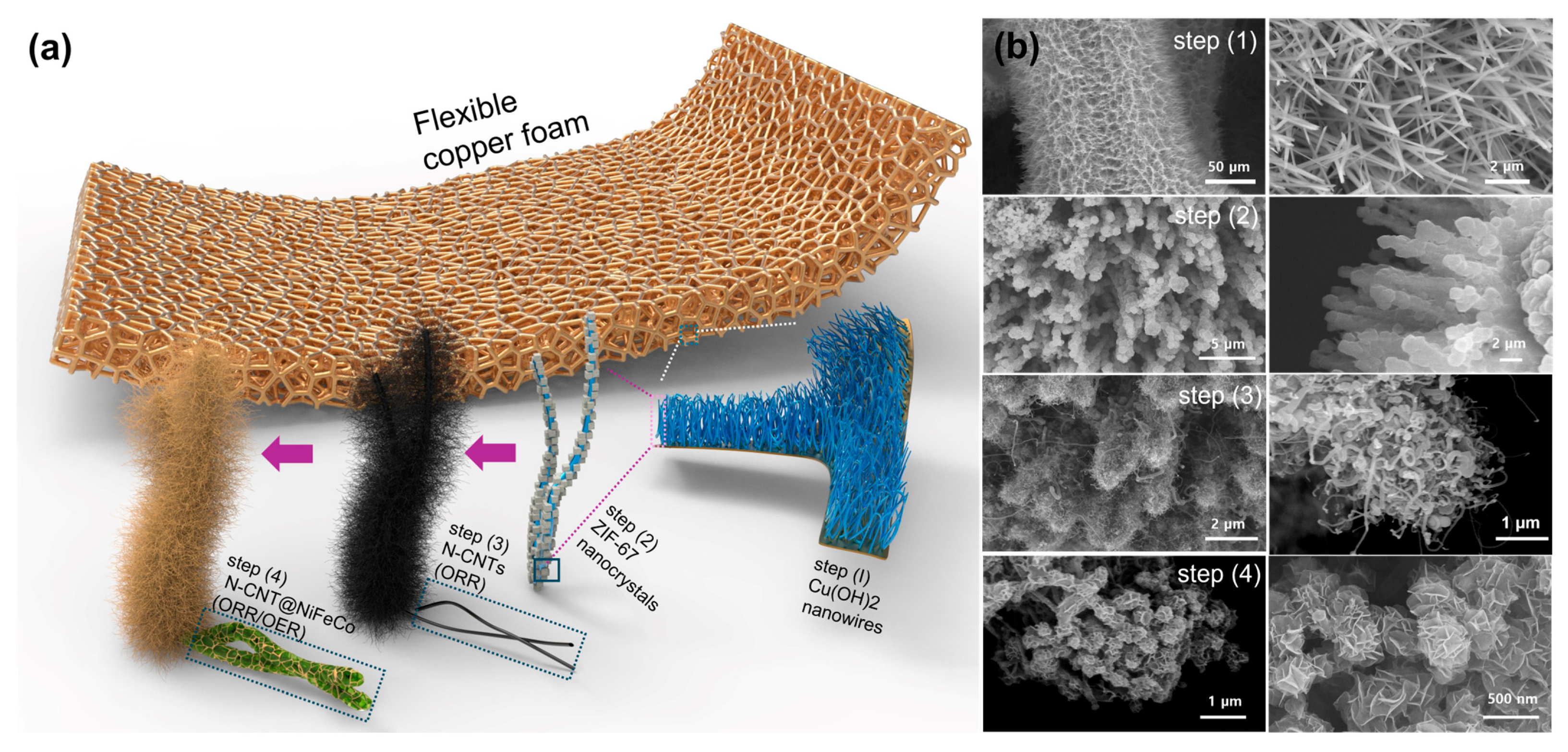
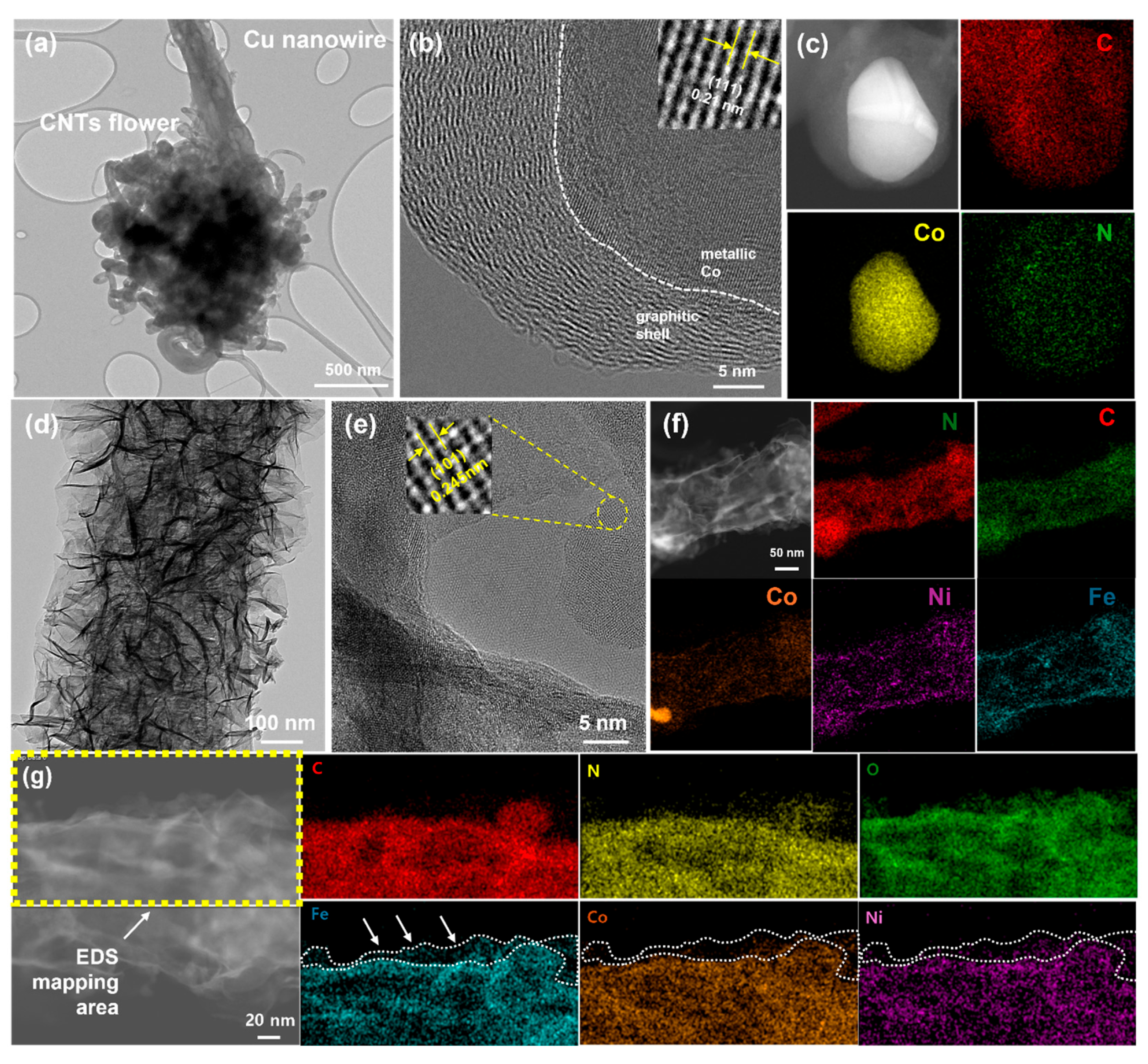
3.1. Structural and Morphological Characterization of Copper Foam-Based Electrodes

The hierarchical structure of the bifunctional air electrode was synthesized through a multi-step fabrication process, as illustrated in Figure 1a. Unlike previous approaches that focused primarily on optimizing a single catalytic activity (typically ORR) with moderate OER performance, this work targets the simultaneous enhancement of both ORR and OER while maintaining structural flexibility. To achieve this challenging goal, the multi-step fabrication process was designed to ensure precise control over CNT growth, catalyst dispersion, and interfacial integration. Flexible copper foam (CuF) was selected as the substrate due to its high electrical conductivity, mechanical durability, and chemical stability during carbon nanotube (CNT) growth in the presence of melamine powder. The fabrication process commenced with the growth of vertically aligned Cu(OH)2 nanowires on CuF (step 1), followed by the deposition of zeolitic imidazolate framework-67 (ZIF-67) nanocrystals onto the nanowires (step 2). The ZIF-67 was then converted into Co-doped nitrogen–carbon nanotubes (N-CNTs) through a single-step pyrolysis process under an argon atmosphere with melamine powder (step 3). Finally, NiFeCo hydroxide nanosheets were uniformly coated onto the CNT network (step 4), introducing additional OER activity while preserving the ORR activity of the N-CNTs. The structural evolution throughout the fabrication process was characterized using FE-SEM, as shown in Figure 1b. In step 1, high-density Cu(OH)2 nanowires were uniformly grown on CuF, forming a vertically aligned structure (Figure S1). In step 2, after ZIF-67 deposition, ZIF-67 particles were successfully anchored onto the nanowire arrays, exhibiting a well-defined polyhedral morphology (Figure S2). This transformation was further confirmed by the observed color changes in Figure S3, where pristine CuF appeared metallic, while ZIF-67 deposition resulted in a distinct blue hue. The cobalt, nitrogen, and carbon components within the ZIF-67 framework were subsequently converted into Co NPs encapsulated by a nitrogen-doped carbon structure (CoNC) during pyrolysis under an argon atmosphere (Figure S4). The vertically aligned nanowire morphology was retained after conversion into the carbon-rich matrix, as evidenced by Figure S5. Following pyrolysis in the presence of melamine powder, nitrogen-doped CNTs encapsulating metallic Co nanoparticles were successfully grown, forming an interconnected conductive framework (Figure S6). Although the 2-methylimidazole ligands in ZIF-67 may provide limited carbon sources upon pyrolysis, the introduction of melamine significantly accelerates CNT nucleation by supplying abundant gaseous nitrogen and carbon species [29,30,31]. In combination with site-localized cobalt catalysts derived from ZIF-67, this approach enables spatially controlled and uniform growth of nitrogen-doped CNTs. FE-SEM images in Figure S7 further confirm that the initial Cu(OH)2 nanowires acted as effective templates for CNT growth, maintaining their vertical alignment after thermal conversion. The resulting N-CNT network provided a high surface area for ORR catalysis while ensuring efficient electron transport. The color transition from blue to black, as depicted in Figure S2, indicates the successful carbonization of ZIF-67 and the subsequent CNT formation. Additionally, multiple CuF samples (2 × 4 cm2), typically 10–12 per batch, were prepared through a single-batch process following the growth of Co(OH)2 nanowires, as shown in Figure S8a. These samples then underwent a single-step annealing process (Figure S8b), resulting in the formation of CNT-coated black electrodes. Similarly, Figure S8c,d present six CuF samples (4 × 4 cm2) before and after pyrolysis, where the ZIF-67-coated samples appear blue, while the CNT-grown samples turned black, confirming the structural transformation during the thermal process. In the final step, NiFeCo hydroxide nanosheets were conformally deposited onto the CNT structure, as observed in Figure 1b (step 4) and Figure S9. FE-SEM images reveal that ultrathin nanosheets were uniformly coated onto the CNT surface, ensuring intimate contact between the catalyst layer and the conductive framework. The color change to reddish-brown, as shown in Figure S10, further confirms the successful deposition of NiFeCo hydroxide.
To gain deeper insight into the structural characteristics and elemental distribution of the synthesized electrodes, HR-TEM and STEM combined with energy-dispersive X-ray spectroscopy (EDS) mapping were conducted, as shown in Figure 2. The TEM image in Figure 2a reveals a CNT flower-like structure attached to the tip of a Cu nanowire, indicating that CNTs nucleate and grow outward from ZIF-67-derived cobalt nanoparticles. This morphology suggests that ZIF-67 serves as a catalyst and template for CNT growth, with carbon diffusing outward to form an extended conductive network. The presence of cobalt at the core is further confirmed by the HR-TEM image in Figure 2b, where a well-defined metallic Co core encapsulated within a graphitic shell is observed. The inset of Figure 2b shows a lattice fringe spacing of 0.21 nm, corresponding to the (111) facet of metallic Co and confirming its crystalline nature. The corresponding STEM/EDS elemental mapping in Figure 2c further verifies this structural configuration, showing a clear spatial separation where cobalt is concentrated in the core, while nitrogen and carbon are uniformly distributed throughout the CNT matrix. The encapsulation of Co within a graphitic shell is further supported by additional HR-TEM images in Figure S11. Upon the electrodeposition of NiFeCo hydroxide, a distinct change in morphology and elemental distribution is observed, as depicted in Figure 2d–f. The TEM image in Figure 2d illustrates the presence of NiFeCo hydroxide conformally coated on the N-CNT network, forming an additional catalytic layer. The HR-TEM image in Figure 2e further confirms the crystalline nature of the deposited hydroxide layer, with the inset highlighting a lattice fringe spacing of 0.245 nm, corresponding to the (101) facet of NiFeCo LDH. The STEM image and corresponding EDS mapping in Figure 2f distinctly show that, while nitrogen and carbon remain homogeneously distributed within the CNT framework, Ni, Fe, and Co are predominantly located in the outer shell, highlighting the successful formation of a well-defined core–shell heterostructure. This elemental distribution is further validated by the EDS elemental mapping profile of another region in Figure 2g, which demonstrates a clear distinction between the inner N/C-rich core and the outer Ni/Fe/Co hydroxide shell. Additionally, EDS line scan analysis (Figure S12) further confirms the spatial segregation of elements, where carbon and nitrogen dominate the inner region and transition metals (Ni, Fe, Co) are predominantly located near the surface. This observation supports the formation of a core–shell heterostructure with an ultrathin catalytic shell. The well-defined interface between the two catalytic components ensures that the ORR-active N-CNT core remains electronically conductive while the OER-active NiFeCo hydroxide shell enhances OER activity without obstructing ORR sites. This structural arrangement minimizes unwanted interference between ORR and OER, thereby optimizing the electrode for bifunctional electrocatalysis.

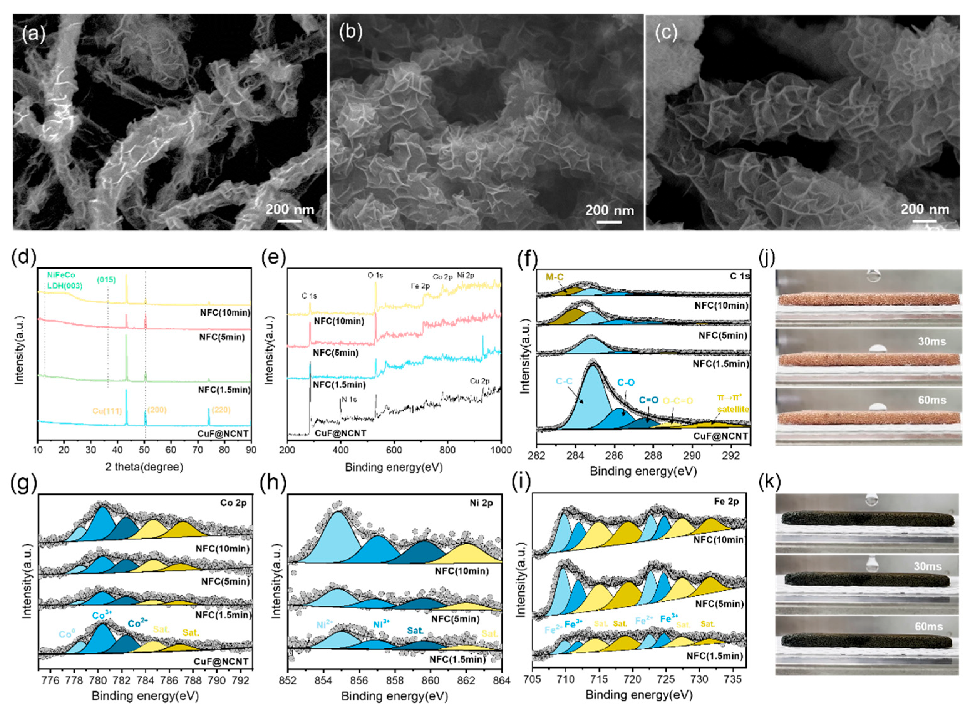
3.2. Chemical Composition and Surface Characteristics of CuF-Based Electrodes

To investigate the structural evolution and chemical composition of the synthesized electrodes, FE-SEM, XRD, and XPS analyses were conducted, as shown in Figure 3. These analyses confirm the successful synthesis of each component and highlight the effect of NiFeCo hydroxide (NFC) electrodeposition time (1.5, 5, and 10 min) on the electrode structure, particularly in terms of coating thickness and surface composition. The FE-SEM images in Figure 3a–c illustrate the progressive increase in NFC coating layer thickness with extended deposition time. The nanostructured NiFeCo hydroxide layers gradually envelop the N-CNT surface, demonstrating the controlled growth of the catalyst layer. The XRD patterns in Figure 3d further corroborate this structural evolution. Due to significant peak overlap between metallic Cu and transition metals, such as Ni, Fe, and Co, distinguishing individual metal phases remains challenging. However, with increasing NFC deposition time, the relative intensity of peaks corresponding to NiFeCo LDH becomes more pronounced, indicating the successful formation and thickening of the hydroxide layer. A similar trend is observed in the XPS survey spectra shown in Figure 3e. As the NFC deposition time increases, the intensity of the N 1s and C 1s peaks, which are dominant in CuF@NCNT, gradually decreases due to the growing hydroxide layer covering the N-CNT framework. Conversely, the relative intensity of Fe 2p, Co 2p, and Ni 2p peaks increases, further confirming the progressive accumulation of NFC. High-resolution XPS spectra provide additional insights into the chemical changes occurring with NFC deposition. The high-resolution C 1s spectrum in Figure 3f and the N 1s spectrums in Figure S13a,b exhibit decreasing peak intensities with increasing NFC thickness, reinforcing the observation that the hydroxide layer partially covers the N-CNT active sites. In contrast, the high-resolution spectra of Co 2p, Ni 2p, and Fe 2p in Figure 3g–i display a noticeable enhancement in peak intensity as the deposition time increases, confirming the gradual accumulation of NiFeCo hydroxide on the electrode surface. A similar trend is observed in the O 1s spectra in Figure S14, where signals corresponding to metal–oxygen bonding and hydroxyl groups intensify with increasing NFC thickness. Comprehensive XPS fitting results including binding energies, FWHM values, and relative peak areas are summarized in Tables S1 and S2, enabling a consistent comparison of C 1s, Co 2p, Ni 2p, and Fe 2p spectra across representative samples. In addition to structural and chemical characterization, the wettability of the electrodes was evaluated through water contact angle measurements, as depicted in Figure 3j,k. While pristine copper foam exhibits a moderate contact angle with water, CuF@NCNT@NFC electrodes demonstrate ultrahydrophilic behavior, with water droplets being immediately absorbed upon contact. This enhanced wettability suggests that the NFC layer significantly improves electrolyte accessibility, which is beneficial for electrochemical performance. Overall, these results confirm the successful fabrication of CuF@NCNT@NFC electrodes and demonstrate that NFC deposition time directly influences the balance between N-CNT exposure and NFC coverage. The ability to fine-tune NFC layer thickness offers a practical approach to optimizing bifunctional electrocatalysis by regulating the proportion of ORR-active N-CNT sites and OER-active NiFeCo hydroxide coverage.

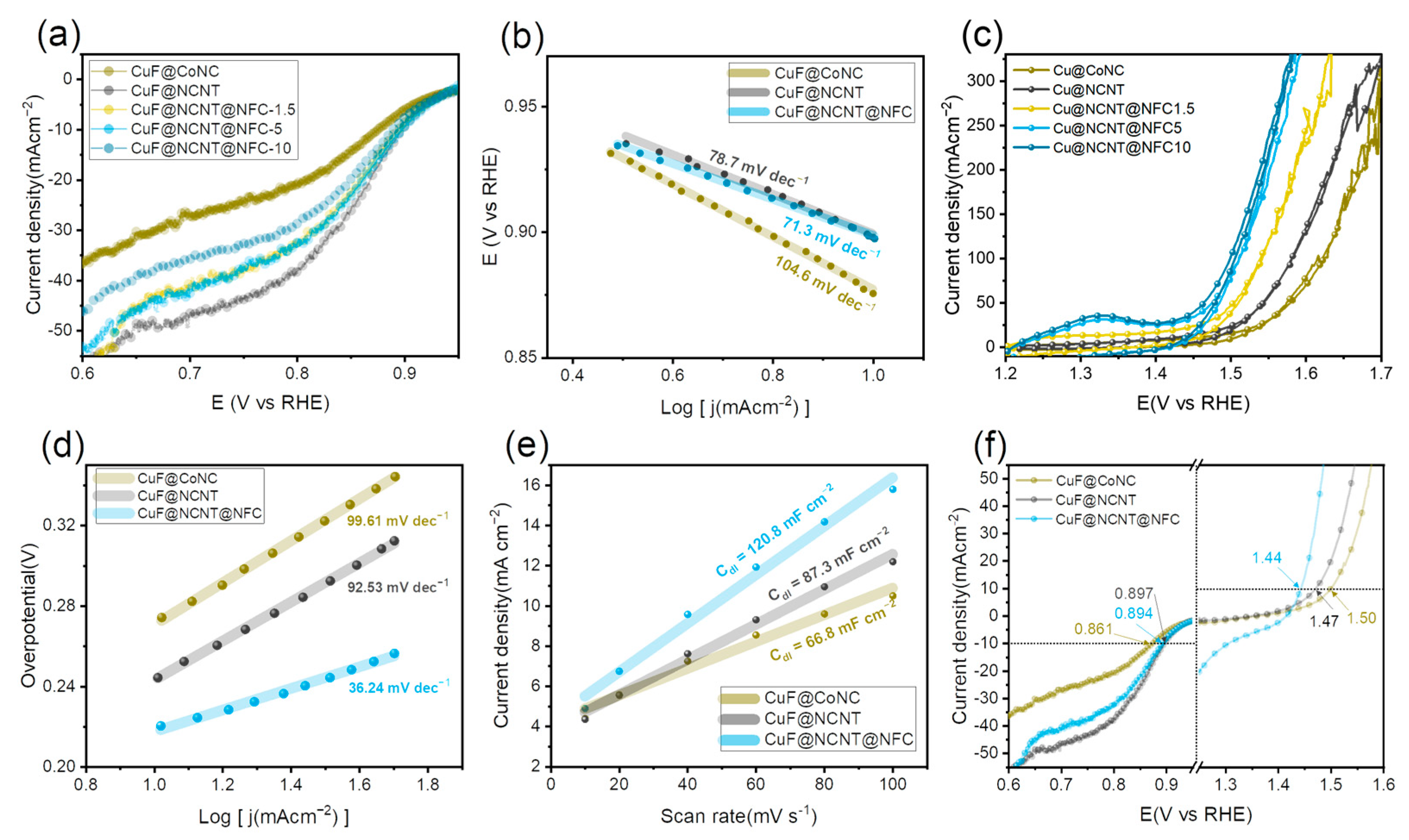
3.3. Electrochemical Performance Evaluation

The electrocatalytic activity of the synthesized electrodes was evaluated in a three-electrode configuration using 1 M KOH, as shown in Figure 4. The results demonstrate how NFC deposition time influences both ORR and OER performance, highlighting the interplay between the N-CNT active sites and the NiFeCo hydroxide coating layer. The ORR activity, presented in Figure 4a, shows a significant improvement for CuF@NCNT compared to CuF@CoNC, confirming the superior catalytic properties of Co-encapsulating N-doped CNTs. Upon NFC deposition, the ORR activity gradually decreases as the coating thickness increases. However, when the deposition time is 1.5 or 5 min, the activity remains nearly unchanged, suggesting that a thin NFC layer does not obstruct the ORR-active sites. In contrast, with a 10 min deposition, the ORR activity declines more noticeably, likely due to excessive catalyst coverage limiting oxygen diffusion and electron transport. The potential required to reach 10 mA cm−2 shifts from 0.861 V vs. RHE for CuF@CoNC to 0.897 V vs. RHE for CuF@NCNT. With NFC deposition, the potential remains at 0.897 V vs. RHE for CuF@NCNT@NFC (1.5 min), slightly decreases to 0.894 V vs. RHE for CuF@NCNT@NFC (5 min), and further declines to 0.889 V vs. RHE for CuF@NCNT@NFC (10 min), indicating a gradual loss in ORR activity with increasing NFC thickness. LSV measurements under N2-saturated conditions (Figure S15) confirm that the cathodic current in O2-saturated electrolyte originates from the ORR, as a negligible current was observed in N2 across the ORR potential window (0.6–1.0 VRHE), except for a minor background current below ~0.75 VRHE, likely arising from residual Cu-based surface oxides. The corresponding Tafel slopes in Figure 4b support these trends. CuF@NCNT and CuF@NCNT@NFC exhibit nearly identical slopes of 71.3 mV dec−1 and 78.7 mV dec−1, respectively, indicating that a moderate NFC coating does not significantly alter ORR kinetics. In contrast, CuF@CoNC displays a considerably higher Tafel slope of 104.6 mV dec−1, highlighting its relatively sluggish ORR kinetics. The OER activity, shown in Figure 4c, follows the opposite trend. Overpotential values were carefully extracted from the reverse direction of CVs to avoid overestimation caused by faradaic contributions from the redox peaks observed in the OER region. As the NFC deposition time increases, the OER performance improves, confirming the role of NiFeCo hydroxide in facilitating OER catalysis. The overpotential required to achieve 100 mA cm−2 decreases as the NFC layer thickens. CuF@CoNC requires 1.626 V, corresponding to an overpotential of 396 mV, while CuF@NCNT requires 1.582 V (352 mV). With NFC deposition, the potential further decreases to 1.542 V (312 mV) for CuF@NCNT@NFC (1.5 min), 1.512 V (282 mV) for CuF@NCNT@NFC (5 min), and 1.505 V (275 mV) for CuF@NCNT@NFC (10 min), showing that NFC deposition significantly enhances OER activity, with further improvements becoming marginal beyond 5 min. The Tafel slopes in Figure 4d follow a similar trend. The NFC-coated electrode exhibits the lowest Tafel slope of 36.24 mV dec−1, indicating the most favorable OER kinetics, whereas CuF@NCNT and CuF@CoNC show higher slopes of 92.53 mV dec−1 and 99.61 mV dec−1, respectively. A comparative summary of OER kinetics is provided in Table S3, where our CuF@NCNT@NFC electrode exhibits a low overpotential (η100 = 282 mV) and an excellent Tafel slope (36.24 mV dec−1), highlighting its competitive performance among recent bifunctional air electrocatalysts [19,21,32,33,34,35,36,37,38]. Since the present system adopts a monolithic electrode design, only OER kinetics were benchmarked, while ORR evaluation was conducted under device-relevant conditions. Considering its application as an air cathode for ZABs, it is important to note that although ORR and OER occur during different stages (discharge and charge, respectively), their active sites are distributed across the same electrode surface. Consequently, excessive deposition of the OER-active NFC layer may partially obstruct the ORR-active N-CNT regions or impede oxygen transport pathways, thereby introducing functional interference between the two catalytic processes. To visualize the trade-off between oxygen reduction and evolution performance, the ORR and OER potentials at 10 and 20 mA cm−2 are plotted as a function of NFC deposition time in Figure S16. As NFC thickness increases, the ORR potential decreases slightly due to the partial coverage of active CNT sites, while the OER potential improves significantly, especially up to 5 min. The curves suggest that a deposition time of 5 min achieves the most favorable bifunctional balance, minimizing the voltage gap between ORR and OER. To estimate the electrochemical surface area (ECSA), CV measurements were performed at different scan rates, as shown in Figure S17a–c. As presented in Figure 4e, the electrochemical double-layer capacitance (Cdl) values were calculated from the slope of the capacitive current versus scan rate. The calculated Cdl value of 66.8 mF cm−2 for CuF@CoNC is significantly improved by the growth of N-CNTs, leading to a Cdl value of 87.3 mF cm−2 for CuF@NCNT. The additional NFC layer further increases this value to 120.8 mF cm−2 for CuF@NCNT@NFC, demonstrating the enhanced electrochemically active surface area provided by NFC deposition. The bifunctional catalytic performance was assessed by evaluating the potential difference (ΔE) between the ORR (E@-10 mA cm−2) and OER (E@10 mA cm−2) potentials, as shown in Figure 4f. A smaller ΔE represents superior bifunctionality. The CuF@CoNC electrode exhibits the largest ΔE of 0.639 V at 10 mA cm−2, calculated from the difference between the OER potential (1.50 V vs. RHE) and ORR potential (0.861 V vs. RHE). CuF@NCNT demonstrates a reduced ΔE of 0.573 V (1.47 V–0.897 V), while CuF@NCNT@NFC achieves the smallest ΔE of 0.546 V (1.44 V–0.894 V), confirming that NFC deposition enhances OER activity while maintaining ORR performance, thereby optimizing bifunctional electrocatalysis. Despite the partial coverage of ORR-active N-CNT sites by the NFC layer, ORR performance remains relatively stable. This can be attributed to several factors. First, the NFC layer is sufficiently thin at optimized deposition times (1.5 and 5 min), allowing for efficient oxygen diffusion to the underlying N-CNT active sites. Second, the intimate contact between the NFC layer and N-CNT network ensures effective charge transfer, minimizing electrical resistance. Third, the highly porous nature of the deposited NiFeCo hydroxide layer facilitates electrolyte penetration, maintaining access to ORR-active regions. Additionally, NiFeCo hydroxide itself may provide some intrinsic ORR activity, further compensating for the potential loss of N-CNT active sites. These synergistic effects allow NFC-coated electrodes to retain ORR activity while significantly enhancing OER performance, demonstrating a well-balanced bifunctional catalytic system suitable for rechargeable zinc–air battery applications.

3.4. Fabrication and Electrochemical Performance of Pouch-Type Solid-State Zinc–Air Batteries

The practical applicability of the synthesized bifunctional air electrodes was demonstrated by assembling sandwich-type ZABs using a well-known PMMA-based gel electrolyte [39]. The electrochemical performance of the ZABs, including polarization curves, power density, cycling stability, mechanical flexibility, and large-scale applications, was systematically investigated, as shown in Figure 5. The charge–discharge polarization curves in Figure 5a reveal the voltage response of ZABs under different current densities. CuF@CoNC exhibits the largest voltage gap between charge and discharge, indicating the lowest efficiency among the tested electrodes. The introduction of N-doped CNTs in CuF@NCNT significantly improves performance, enhancing both ORR and OER activities due to the presence of Co species within the nitrogen-doped carbon matrix. Further NFC coating leads to a notable enhancement, particularly in the OER region, while maintaining comparable ORR activity. At high current densities, NFC-coated electrodes even outperform CuF@NCNT in ORR, suggesting that NFC contributes to improved mass transport and charge transfer at elevated reaction rates. The peak power density, shown in Figure 5b, was measured under ambient air conditions without additional oxygen supply. The NFC-coated electrode achieves the highest peak power density of 55.09 mW cm−2, surpassing CuF@NCNT (43.54 mW cm−2) and CuF@CoNC (40.93 mW cm−2). These results highlight the critical role of NFC in enhancing the electrocatalytic efficiency of ZABs, particularly in achieving superior OER activity without compromising ORR performance. To optimize NFC deposition time, ZABs were evaluated for different NFC coating durations, as presented in Figure 5c. The results indicate that 5 min of deposition yields the best performance, whereas further increasing the deposition time deteriorates both ORR and OER activities. This degradation is likely due to the thickening of the NFC layer, which, while initially enhancing OER activity, eventually introduces excessive electrical resistance that hinders overall charge transport. The mechanical flexibility of the ZABs was assessed by bending the device from 0° to 150°, as shown in Figure 5d. The performance remains stable across different bending angles, confirming the structural robustness and flexibility of the assembled ZABs. Although metallic substrates, such as Cu foam, are intrinsically less flexible than polymer- or textile-based alternatives, the observed tolerance to bending demonstrates sufficient mechanical compliance for semi-flexible device applications. The stretchability of the PMMA-based gel electrolyte was also evaluated, as shown in Figure S18, further supporting its suitability for flexible energy storage devices. The long-term cycling stability of the ZABs was investigated under different current densities. Figure 5e presents the cycling performance at 5 mA cm−2 with a 10 min cycle time, where the device operates continuously for 350 h. The voltage gap remains stable at 0.47 V for the first 250 h, after which a gradual increase is observed, reaching 0.77 V at 350 h, indicating slight degradation over prolonged operation. When the current density is doubled to 10 mA cm−2, as shown in Figure 5f, the voltage gap starts at 0.75 V and remains stable for 100 h, after which a slight increase to 0.84 V is observed. Additionally, Figure S19 provides a magnified view of the initial charge–discharge cycles, displaying well-defined plateau regions, further confirming the stability of the electrochemical reactions during operation. These results demonstrate the excellent cycling durability of the NFC-coated electrodes under practical operating conditions. A performance comparison with recent solid-state ZABs is summarized in Table S4, where our system demonstrates favorable voltage efficiency and cycling stability under practical operating conditions [17,18,33,36,40,41,42,43,44,45,46]. To further explore scalability, bipolar pouch-type ZABs with a 4 × 4 cm2 (16 cm2) active area were fabricated. The assembly process involved placing two air electrodes and a gel electrolyte on both sides of a zinc foil anode to form a bipolar configuration, as shown in Figure S20a,b. The open-circuit voltage (OCV) of the assembled 16 cm2 pouch-type ZAB was directly measured to be 1.426 V, as shown in Figure S21. As presented in Figure 5g, the discharge capacities at different current densities of 5, 10, and 20 mA are recorded as 0.62, 0.50, and 0.49 Ah, respectively. These values confirm the feasibility of NFC-coated electrodes for large-area ZAB configurations. The practical application potential of the fabricated ZABs was demonstrated through various functional tests. Figure 5h shows 2 × 4 cm2 and 4 × 4 cm2 pouch-type ZABs successfully powering an LED light. Furthermore, Figure 5i presents a larger-scale demonstration where four pouch cells are connected in series to charge a smartphone, showcasing the viability of the developed air electrodes. Lastly, the cycling stability of the 16 cm2 pouch-type ZAB was evaluated under a 40 mAh charge–discharge test, as shown in Figure 5j. The device exhibits stable performance for over 130 h, further validating the long-term reliability of NFC-coated electrodes in large-scale ZAB applications. These results collectively confirm that NFC-coated CuF@NCNT electrodes exhibit superior electrocatalytic performance, enhanced mechanical stability, and excellent scalability, making them highly suitable for practical zinc–air battery applications. While our work primarily focuses on the design of high-performance air cathodes, it is worth noting that zinc metal anodes in gel electrolyte systems are generally less susceptible to dendritic growth and interfacial instability compared to those in liquid electrolytes [47]. Nevertheless, potential crosstalk between the air cathode and zinc anode may still emerge during prolonged cycling, thus warranting further investigation in future studies.

4. Discussion

This study demonstrates the successful design of a scalable bifunctional air electrode by integrating N-doped CNTs with NiFeCo hydroxide on CuF, achieving an optimized balance between ORR and OER activity. Compared to conventional Pt/C- and RuO2-based catalysts, the CuF@NCNT@NFC electrode offers superior electrocatalytic performance, enhanced durability, and cost effectiveness while maintaining excellent mechanical flexibility. The minimized potential gap (ΔE) of 0.546 V at 10 mA cm−2 confirms the synergistic effect of the hierarchical structure in facilitating oxygen electrocatalysis, while the ultrahydrophilic nature improves electrolyte accessibility for stable operation. The successful fabrication of a 16 cm2 bipolar pouch-type ZAB, with a discharge capacity of 0.62 Ah at 5 mA cm−2, validates the scalability and practical viability of this electrode for large-area applications, including flexible and wearable energy storage devices. Future studies should focus on further extending cycling stability, exploring in situ characterization techniques, optimizing solid-state electrolytes, and integrating ZABs with hybrid energy storage systems for real-world applications.

Supplementary Materials

The following supporting information can be downloaded at: https://www.mdpi.com/article/10.3390/batteries11040155/s1, Figure S1. FE-SEM images of Cu(OH)₂ nanowire arrays grown on CuF, Figure S2. FE-SEM images of ZIF-67-coated Cu(OH)₂ nanowires on CuF, Figure S3. Photograph images of CuF-based electrodes at different fabrication stages, Figure S4. FE-SEM images of CuF@CoNC obtained after pyrolysis of ZIF-67-coated Cu(OH)₂ nanowires, Figure S5. FE-SEM images showing retention of nanowire morphology in CuF@CoNC after pyrolysis, Figure S6. FE-SEM images of CuF@NCNT after pyrolysis with g-C₃N₄, Figure S7. FE-SEM images of vertically aligned Cu(OH)₂ nanowires converted into CoNC, Figure S8. Photograph images of CuF samples before and after ZIF-67 deposition and CNT pyrolysis, Figure S9. FE-SEM images of CuF@NCNT@NFC with NiFeCo hydroxide coating, Figure S10. Photograph image of CuF@NCNT@NFC after hydroxide deposition, Figure S11. HR-TEM image of Co nanoparticle in graphitic carbon shell, Figure S12. STEM image and EDS line scan profile showing core–shell structure, Figure S13. High-resolution N 1s spectra of CuF@NCNT and CuF@NCNT@NFC, Figure S14. High-resolution O 1s spectra of CuF@NCNT and CuF@NCNT@NFC, Figure S15. LSV curves of CuF@CoNC, CuF@NCNT, and CuF@NCNT@NFC electrodes, Figure S16. Comparison of ORR and OER potentials versus NFC deposition time, Figure S17. CV curves at different scan rates for all samples, Figure S18. Photographs and stretchability of PMMA gel electrolyte, Figure S19. Charge–discharge cycling profiles of the pouch-type ZAB, Figure S20. Components of the single-cell and bipolar pouch-type ZAB, Figure S21. OCV measurement of the solid-state zinc–air battery, Table S1. Summary of high-resolution XPS fitting parameters of C 1s and Co 2p spectra, Table S2. Summary of XPS fitting parameters for Ni 2p and Fe 2p spectra, Table S3. Comparison of OER kinetic parameters of CuF@NCNT@NFC with various catalysts, Table S4. Comparison of zinc–air battery performance using different bifunctional air electrodes with solid-state electrolytes.

Author Contributions

Conceptualization, A.L. and S.H.A.; Methodology, A.L. and Y.-W.K.; Investigation, A.L. and Y.-W.K.; Data Curation, Y.-W.K.; Writing—Original Draft Preparation, S.H.A.; Writing—Review and Editing, S.H.A.; Visualization, Y.-W.K.; Supervision, S.H.A. All authors have read and agreed to the published version of the manuscript.

Funding

This research was supported by a research fund from Chosun University, 2020.

Data Availability Statement

The data presented in this study are available on request from the corresponding author.

Acknowledgments

The authors acknowledge the assistance of the Advanced Institute of Instrumental Analysis (GAIA) at GIST for the cs-corrected STEM analysis and the Center for Research Facilities at Chonnam National University for XRD and XPS analyses.

Conflicts of Interest

The authors declare no conflicts of interest.

Abbreviations

The following abbreviations are used in this manuscript:
ZABZinc–air battery
CuFCopper foam
CNTCarbon nanotube
N-CNTNitrogen-doped carbon nanotube
NFCNiFeCo hydroxide
LDHLayered double hydroxide
ORROxygen reduction reaction
OEROxygen evolution reaction
PMMAPoly(methyl methacrylate)
ECSAElectrochemical surface area
LSVLinear sweep voltammetry
CVCyclic voltammetry
EISElectrochemical impedance spectroscopy
XRDX-ray diffraction
XPSX-ray photoelectron spectroscopy
FE-SEMField-emission scanning electron microscopy
HR-TEMHigh-resolution transmission electron microscopy
STEMScanning transmission electron microscopy
EDSEnergy-dispersive X-ray spectroscopy

References

  1. Zhao, C.X.; Liu, J.N.; Wang, J.; Ren, D.; Li, B.Q.; Zhang, Q. Recent advances of noble-metal-free bifunctional oxygen reduction and evolution electrocatalysts. Chem. Soc. Rev. 2021, 50, 7745–7778. [Google Scholar] [CrossRef] [PubMed]
  2. Gu, P.; Zheng, M.B.; Zhao, Q.X.; Xiao, X.; Xue, H.G.; Pang, H. Rechargeable zinc-air batteries: A promising way to green energy. J. Mater. Chem. A 2017, 5, 7651–7666. [Google Scholar] [CrossRef]
  3. Zhu, Z.X.; Jiang, T.L.; Ali, M.; Meng, Y.H.; Jin, Y.; Cui, Y.; Chen, W. Rechargeable Batteries for Grid Scale Energy Storage. Chem. Rev. 2022, 122, 16610–16751. [Google Scholar] [CrossRef] [PubMed]
  4. Mainar, A.R.; Iruin, E.; Colmenares, L.C.; Kvasha, A.; de Meatza, I.; Bengoechea, M.; Leonet, O.; Boyano, I.; Zhang, Z.C.; Blazquez, J.A. An overview of progress in electrolytes for secondary zinc-air batteries and other storage systems based on zinc. J. Energy Storage 2018, 15, 304–328. [Google Scholar] [CrossRef]
  5. Zhu, Y.H.; Yang, X.Y.; Liu, T.; Zhang, X.B. Flexible 1D Batteries: Recent Progress and Prospects. Adv. Mater. 2020, 32, 1901961. [Google Scholar] [CrossRef]
  6. Tan, P.; Chen, B.; Xu, H.R.; Zhang, H.C.; Cai, W.Z.; Ni, M.; Liu, M.L.; Shao, Z.P. Flexible Zn- and Li-air batteries: Recent advances, challenges, and future perspectives. Energy Environ. Sci. 2017, 10, 2056–2080. [Google Scholar] [CrossRef]
  7. Liu, Q.C.; Chang, Z.W.; Li, Z.J.; Zhang, X.B. Flexible Metal-Air Batteries: Progress, Challenges, and Perspectives. Small Methods 2018, 2, 1700231. [Google Scholar] [CrossRef]
  8. Wang, S.G.; Qin, J.W.; Meng, T.; Cao, M.H. Metal-organic framework-induced construction of actiniae-like carbon nanotube assembly as advanced multifunctional electrocatalysts for overall water splitting and Zn-air batteries. Nano Energy 2017, 39, 626–638. [Google Scholar] [CrossRef]
  9. Chang, H.; Guo, Y.F.; Liu, X.; Wang, P.F.; Xie, Y.; Yi, T.F. Dual MOF-derived Fe/N/P-tridoped carbon nanotube as high-performance oxygen reduction catalysts for zinc-air batteries. Appl. Catal. B-Environ. Energy 2023, 327, 122469. [Google Scholar] [CrossRef]
  10. Liu, X.; Liu, W.; Ko, M.; Park, M.; Kim, M.G.; Oh, P.; Chae, S.; Park, S.; Casimir, A.; Wu, G.; et al. Metal (Ni, Co)-Metal Oxides/Graphene Nanocomposites as Multifunctional Electrocatalysts. Adv. Funct. Mater. 2015, 25, 5799–5808. [Google Scholar] [CrossRef]
  11. Tang, C.; Wang, B.; Wang, H.F.; Zhang, Q. Defect Engineering toward Atomic Co-Nx-C in Hierarchical Graphene for Rechargeable Flexible Solid Zn-Air Batteries. Adv. Mater. 2017, 29, 1703185. [Google Scholar] [CrossRef] [PubMed]
  12. Yang, H.B.; Miao, J.W.; Hung, S.F.; Chen, J.Z.; Tao, H.B.; Wang, X.Z.; Zhang, L.P.; Chen, R.; Gao, J.J.; Chen, H.M.; et al. Identification of catalytic sites for oxygen reduction and oxygen evolution in N-doped graphene materials: Development of highly efficient metal-free bifunctional electrocatalyst. Sci. Adv. 2016, 2, 1501122. [Google Scholar] [CrossRef] [PubMed]
  13. Zeng, M.; Liu, Y.L.; Zhao, F.P.; Nie, K.Q.; Han, N.; Wang, X.X.; Huang, W.J.; Song, X.N.; Zhong, J.; Li, Y.G. Metallic Cobalt Nanoparticles Encapsulated in Nitrogen-Enriched Graphene Shells: Its Bifunctional Electrocatalysis and Application in Zinc-Air Batteries. Adv. Funct. Mater. 2016, 26, 4397–4404. [Google Scholar] [CrossRef]
  14. Wang, Z.; Ang, J.M.; Liu, J.; Ma, X.Y.D.; Kong, J.H.; Zhang, Y.F.; Yan, T.; Lu, X.H. FeNi alloys encapsulated in N-doped CNTs-tangled porous carbon fibers as highly efficient and durable bifunctional oxygen electrocatalyst for rechargeable zinc-air battery. Appl. Catal. B-Environ. 2020, 263, 118344. [Google Scholar] [CrossRef]
  15. Hao, X.Q.; Jiang, Z.Q.; Zhang, B.A.; Tian, X.N.; Song, C.S.; Wang, L.K.; Maiyalagan, T.; Hao, X.G.; Jiang, Z.J. N-Doped Carbon Nanotubes Derived from Graphene Oxide with Embedment of FeCo Nanoparticles as Bifunctional Air Electrode for Rechargeable Liquid and Flexible All-Solid-State Zinc-Air Batteries. Adv. Sci. 2021, 8, 2004572. [Google Scholar] [CrossRef]
  16. Jiang, Y.; Deng, Y.-P.; Liang, R.; Fu, J.; Luo, D.; Liu, G.; Li, J.; Zhang, Z.; Hu, Y.; Chen, Z. Multidimensional Ordered Bifunctional Air Electrode Enables Flash Reactants Shuttling for High-Energy Flexible Zn-Air Batteries. Adv. Energy Mater. 2019, 9, 1900911. [Google Scholar] [CrossRef]
  17. Jin, Q.; Ren, B.; Cui, H.; Wang, C. Nitrogen and cobalt co-doped carbon nanotube films as binder-free trifunctional electrode for flexible zinc-air battery and self-powered overall water splitting. Appl. Catal. B-Environ. 2021, 283, 119643. [Google Scholar] [CrossRef]
  18. Tian, W.-W.; Ren, J.-T.; Yuan, Z.-Y. In-situ cobalt-nickel alloy catalyzed nitrogen-doped carbon nanotube arrays as superior freestanding air electrodes for flexible zinc-air and aluminum-air batteries. Appl. Catal. B-Environ. 2022, 317, 121764. [Google Scholar] [CrossRef]
  19. Wang, Y.; Gao, Y.; Ma, L.; Xue, Y.; Liu, Z.-H.; Cui, H.; Zhang, N.; Jiang, R. Atomically Dispersed Fe–N4 Sites and NiFe-LDH Sub-Nanoclusters as an Excellent Air Cathode for Rechargeable Zinc–Air Batteries. ACS Appl. Mater. Interfaces 2023, 15, 16732–16743. [Google Scholar] [CrossRef]
  20. Chen, D.; Chen, X.; Cui, Z.; Li, G.; Han, B.; Zhang, Q.; Sui, J.; Dong, H.; Yu, J.; Yu, L.; et al. Dual-active-site hierarchical architecture containing NiFe-LDH and ZIF-derived carbon-based framework composite as efficient bifunctional oxygen electrocatalysts for durable rechargeable Zn-air batteries. Chem. Eng. J. 2020, 399, 125718. [Google Scholar] [CrossRef]
  21. Chang, F.; Du, H.; Su, P.; Sun, Y.; Ye, R.; Tian, Q.; Zhang, G.; Li, H.; Liu, J. Facile Synthesis of Vertical Layered Double Hydroxides Nanosheets on Co@Carbon Nanoframes as Robust Bifunctional Oxygen Electrocatalysts for Rechargeable Zn–Air Batteries. Small Struct. 2024, 5, 2300111. [Google Scholar] [CrossRef]
  22. Wang, W.-H.; Han, C.-H.; Hong, W.-X.; Chiu, Y.-C.; Tseng, I.H.; Chang, Y.-H.; Pourzolfaghar, H.; Li, Y.-Y. NiFe layered double hydroxide (LDH) anchored, Fe single atom and nanoparticle embedded on nitrogen-doped carbon-CNT (carbon nanotube) framework as a bifunctional catalyst for rechargeable zinc-air batteries. J. Energy Storage 2024, 85, 111058. [Google Scholar] [CrossRef]
  23. Allwyn, N.; Gokulnath, S.; Sathish, M. In-Situ Nanoarchitectonics of Fe/Co LDH over Cobalt-Enriched N-Doped Carbon Cookies as Facile Oxygen Redox Electrocatalysts for High-Rate Rechargeable Zinc–Air Batteries. ACS Appl. Mater. Interfaces 2024, 16, 20360–20374. [Google Scholar] [CrossRef] [PubMed]
  24. Yu, L.; Zhou, H.; Sun, J.; Qin, F.; Luo, D.; Xie, L.; Yu, F.; Bao, J.; Li, Y.; Yu, Y.; et al. Hierarchical Cu@CoFe layered double hydroxide core-shell nanoarchitectures as bifunctional electrocatalysts for efficient overall water splitting. Nano Energy 2017, 41, 327–336. [Google Scholar] [CrossRef]
  25. Yu, L.; Zhou, H.; Sun, J.; Qin, F.; Yu, F.; Bao, J.; Yu, Y.; Chen, S.; Ren, Z. Cu nanowires shelled with NiFe layered double hydroxide nanosheets as bifunctional electrocatalysts for overall water splitting. Energy Environ. Sci. 2017, 10, 1820–1827. [Google Scholar] [CrossRef]
  26. Li, M.; Xiong, Y.; Liu, X.; Han, C.; Zhang, Y.; Bo, X.; Guo, L. Iron and nitrogen co-doped carbon nanotube@hollow carbon fibers derived from plant biomass as efficient catalysts for the oxygen reduction reaction. J. Mater. Chem. A 2015, 3, 9658–9667. [Google Scholar] [CrossRef]
  27. Park, Y.-E.; Park, S.-H.; Ahn, S.H. Tissue-derived highly compressible anisotropic carbon aerogels with aligned fibrous matrices for solid-state rechargeable zinc-cobalt-air hybrid batteries. EcoMat 2024, 6, e12431. [Google Scholar] [CrossRef]
  28. Son, H.J.; Cho, Y.R.; Park, Y.-E.; Ahn, S.H. Flexible, compressible, versatile biomass-derived freestanding carbon monoliths as binder- and substrate-free tri-functional electrodes for solid-state zinc-air batteries and overall water splitting. Appl. Catal. B-Environ. 2022, 304, 120977. [Google Scholar] [CrossRef]
  29. Zhao, C.; Wang, Y.; Li, Z.; Chen, W.; Xu, Q.; He, D.; Xi, D.; Zhang, Q.; Yuan, T.; Qu, Y.; et al. Solid-Diffusion Synthesis of Single-Atom Catalysts Directly from Bulk Metal for Efficient CO2 Reduction. Joule 2019, 3, 584–594. [Google Scholar] [CrossRef]
  30. Yang, Z.; Zhao, C.; Qu, Y.; Zhou, H.; Zhou, F.; Wang, J.; Wu, Y.; Li, Y. Trifunctional Self-Supporting Cobalt-Embedded Carbon Nanotube Films for ORR, OER, and HER Triggered by Solid Diffusion from Bulk Metal. Adv. Mater. 2019, 31, 1808043. [Google Scholar] [CrossRef]
  31. Zhou, Z.; Lu, J.; Zhang, R.; Cao, Y.; Li, H. Construction and differential growth mechanism of uniform and controllable CNTs and CNWs by ZIF-67 precursor. Appl. Surf. Sci. 2023, 640, 158342. [Google Scholar] [CrossRef]
  32. Milikić, J.; Nastasić, A.; Knežević, S.; Rakočević, L.; Stojadinović, S.; Stanković, D.; Šljukić, B. Efficient nano-size ZnM/rGO (M = Ni, Cu, and Fe) electrocatalysts for oxygen electrode reactions in alkaline media. Int. J. Hydrogen Energy 2025, 97, 247–258. [Google Scholar] [CrossRef]
  33. Yang, X.; Zhou, Z.; Zou, Y.; Kuang, J.; Ye, D.; Zhang, S.; Gao, Q.; Yang, S.; Cai, X.; Fang, Y. Interface reinforced 2D/2D heterostructure of Cu-Co oxides/FeCo hydroxides as monolithic multifunctional catalysts for rechargeable/flexible zinc-air batteries and self-powered water splitting. Appl. Catal. B-Environ. 2023, 325, 122332. [Google Scholar] [CrossRef]
  34. Moloudi, M.; Noori, A.; Rahmanifar, M.S.; Shabangoli, Y.; El-Kady, M.F.; Mohamed, N.B.; Kaner, R.B.; Mousavi, M.F. Layered Double Hydroxide Templated Synthesis of Amorphous NiCoFeB as a Multifunctional Electrocatalyst for Overall Water Splitting and Rechargeable Zinc–Air Batteries. Adv. Energy Mater. 2023, 13, 2203002. [Google Scholar] [CrossRef]
  35. Li, Q.; Sun, Z.; Yin, C.; Chen, Y.; Pan, D.; Yu, B.; Zhang, Y.; He, T.; Chen, S. Template-assisted synthesis of ultrathin graphene aerogels as bifunctional oxygen electrocatalysts for water splitting and alkaline/neutral zinc-air batteries. Chem. Eng. J. 2023, 458, 141492. [Google Scholar] [CrossRef]
  36. Sun, J.; Leng, P.; Xie, Y.; Yu, X.; Qu, K.; Feng, L.; Bao, H.; Luo, F.; Yang, Z. Co single atoms and Co nanoparticle relay electrocatalyst for rechargeable zinc air batteries. Appl. Catal. B-Environ. 2022, 319, 121905. [Google Scholar] [CrossRef]
  37. Cai, X.; Jiang, T.; Wu, M. Confined growth of NiFe LDH with hierarchical structures on copper nanowires for long-term stable rechargeable Zn-air batteries. Appl. Surf. Sci. 2022, 577, 151911. [Google Scholar] [CrossRef]
  38. Zhang, G.W.; Zeng, J.R.; Yin, J.; Zuo, C.Y.; Wen, P.; Chen, H.T.; Qiu, Y.J. Iron-facilitated surface reconstruction to in-situ generate nickel-iron oxyhydroxide on self-supported FeNi alloy fiber paper for efficient oxygen evolution reaction. Appl. Catal. B-Environ. 2021, 286, 119902. [Google Scholar] [CrossRef]
  39. Wang, Q.; Feng, Q.; Lei, Y.; Tang, S.; Xu, L.; Xiong, Y.; Fang, G.; Wang, Y.; Yang, P.; Liu, J.; et al. Quasi-solid-state Zn-air batteries with an atomically dispersed cobalt electrocatalyst and organohydrogel electrolyte. Nat. Commnun. 2022, 13, 3689. [Google Scholar] [CrossRef]
  40. Yang, H.; Gao, S.; Rao, D.; Yan, X. Designing superior bifunctional electrocatalyst with high-purity pyrrole-type CoN4 and adjacent metallic cobalt sites for rechargeable Zn-air batteries. Energy Storage Mater. 2022, 46, 553–562. [Google Scholar] [CrossRef]
  41. Xu, N.N.; Wilson, J.A.; Wang, Y.D.; Su, T.S.; Wei, Y.N.; Qiao, J.L.; Zhou, X.D.; Zhang, Y.X.; Sun, S.H. Flexible self-supported bi-metal electrode as a highly stable carbon- and binder-free cathode for large-scale solid-state zinc-air batteries. Appl. Catal. B-Environ. 2020, 272, 118953. [Google Scholar] [CrossRef]
  42. Liu, T.; Mou, J.R.; Wu, Z.P.; Lv, C.; Huang, J.L.; Liu, M.L. A Facile and Scalable Strategy for Fabrication of Superior Bifunctional Freestanding Air Electrodes for Flexible Zinc-Air Batteries. Adv. Funct. Mater. 2020, 30, 2003407. [Google Scholar] [CrossRef]
  43. Yang, L.; Shi, L.; Wang, D.; Lv, Y.; Cao, D. Single-atom cobalt electrocatalysts for foldable solid-state Zn-air battery. Nano Energy 2018, 50, 691–698. [Google Scholar] [CrossRef]
  44. Ma, L.T.; Chen, S.M.; Pei, Z.X.; Huang, Y.; Liang, G.J.; Mo, F.N.; Yang, Q.; Su, J.; Gao, Y.H.; Zapien, J.A.; et al. Single-Site Active Iron-Based Bifunctional Oxygen Catalyst for a Compressible and Rechargeable Zinc-Air Battery. ACS Nano 2018, 12, 1949–1958. [Google Scholar] [CrossRef] [PubMed]
  45. Wu, K.; Zhang, L.; Yuan, Y.; Zhong, L.; Chen, Z.; Chi, X.; Lu, H.; Chen, Z.; Zou, R.; Li, T.; et al. An Iron-Decorated Carbon Aerogel for Rechargeable Flow and Flexible Zn-Air Batteries. Adv. Mater. 2020, 32, 2002292. [Google Scholar] [CrossRef]
  46. Zhong, X.; Zheng, Z.; Xu, J.; Xiao, X.; Sun, C.; Zhang, M.; Ma, J.; Xu, B.; Yu, K.; Zhang, X.; et al. Flexible Zinc–Air Batteries with Ampere-Hour Capacities and Wide-Temperature Adaptabilities. Adv. Mater. 2023, 35, 2209980. [Google Scholar] [CrossRef]
  47. Ge, B.; Hu, L.; Yu, X.; Wang, L.; Fernandez, C.; Yang, N.; Liang, Q.; Yang, Q.-H. Engineering Triple-Phase Interfaces around the Anode toward Practical Alkali Metal–Air Batteries. Adv. Mater. 2024, 36, 2400937. [Google Scholar] [CrossRef]
Figure 1. Schematic illustration and morphological evolution of the CuF-based bifunctional air electrode. (a) Stepwise fabrication process involving the growth of Cu(OH)2 nanowires on CuF (step 1), deposition of ZIF-67 nanocrystals (step 2), conversion to N-CNTs via pyrolysis (step 3), and final deposition of NiFeCo hydroxide nanosheets (step 4). (b) FE-SEM images corresponding to each fabrication step, showing the structural transformation from Cu(OH)2 nanowires to NiFeCo hydroxide-coated N-CNTs.
Batteries 11 00155 g001
Figure 2. (a) TEM image showing CNT flower structures growing from a Cu nanowire. (b) HR-TEM image of a Co nanoparticle encapsulated within a graphitic shell, with the inset showing a lattice fringe spacing of 0.21 nm corresponding to the (111) facet of metallic Co. (c) STEM image and corresponding EDS elemental mapping images for C, Co, and N. (d) TEM image of N-CNT@NFC. (e) HR-TEM image of the NiFeCo LDH layer, with the inset showing a lattice fringe spacing of 0.245 nm corresponding to the (101) facet of NiFeCo LDH. (f,g) STEM images and the corresponding EDS elemental mapping images, confirming the core–shell heterostructure, where Ni, Fe, and Co are primarily distributed in the outer hydroxide shell.
Batteries 11 00155 g002
Figure 3. (ac) FE-SEM images of CuF@NCNT@NFC electrodes with increasing NFC deposition time, showing the progressive thickening of the NiFeCo hydroxide layer. (d) XRD patterns indicating the structural evolution with increasing NFC deposition, where NiFeCo LDH peaks become more pronounced. (e) XPS survey spectra. (f) High-resolution C 1s spectra comparing CuF@NCNT and NFC-coated CuF@NCNT with different electrodeposition times of 1.5, 5, and 10 min. (gi) Fine XPS spectra of Co 2p, Ni 2p, and Fe 2p for CuF@NCNT@NFC at different electrodeposition times. (j,k) Photographs of water droplets on pristine CuF and CuF@NCNT@NFC, demonstrating the transition to ultrahydrophilic behavior upon NFC deposition.
Batteries 11 00155 g003
Figure 4. (a) ORR polarization curves of CuF@CoNC, CuF@NCNT, and CuF@NCNT@NFC electrodes with varying NFC deposition times in O2-saturated 1 M KOH electrolyte, and (b) the corresponding Tafel slopes derived from panel (a). (c) CV curves of CuF@CoNC, CuF@NCNT, and CuF@NCNT@NFC samples with varying NFC deposition times in 1 M KOH electrolyte toward OER, and (d) corresponding Tafel slopes for OER. (e) Electrochemical double-layer capacitance (Cdl) values estimated from CV measurements at different scan rates. (f) Bifunctional electrocatalytic performance assessed by the potential gap (ΔE) between ORR (E@-10 mA cm−2) and OER (E@10 mA cm−2).
Batteries 11 00155 g004
Figure 5. (a) Charging–discharging polarization curves of solid-state ZABs assembled with CuF@CoNC, CuF@NCNT, and CuF@NCNT@NFC air electrodes. (b) Power density curves of ZABs under ambient air conditions. (c) Cycling stability of ZABs with different NFC deposition times. (d) Mechanical flexibility test of the ZAB under repeated bending. (e,f) Long-term cycling performance of ZABs at an applied current density of 5 and 10 mA cm−2, respectively. (g) Discharge capacities of a 4 × 4 cm2 pouch-type ZAB at different current densities. (h) LED lighting test with pouch-type ZABs of 2 × 4 cm2 and 4 × 4 cm2. (i) Smartphone charging demonstration using four pouch-type ZABs connected in series. (j) Cycling stability test of the 16 cm2 pouch-type ZAB under a 40 mAh charge–discharge protocol.
Batteries 11 00155 g005
Disclaimer/Publisher’s Note: The statements, opinions and data contained in all publications are solely those of the individual author(s) and contributor(s) and not of MDPI and/or the editor(s). MDPI and/or the editor(s) disclaim responsibility for any injury to people or property resulting from any ideas, methods, instructions or products referred to in the content.

