
Study on Mechanical Properties and Microstructural Evolution of Composite Copper Foils Following Long-Term Storage


 and
and 
Abstract
:1. Introduction
2. Experimental
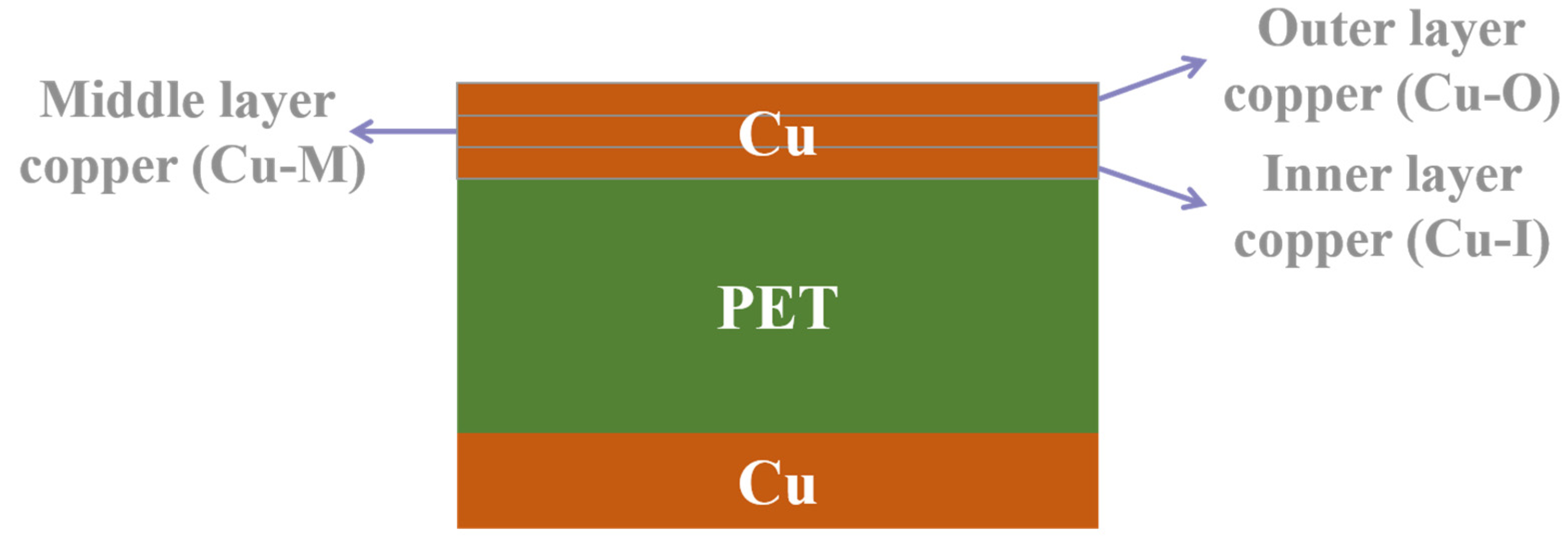
2.1. Materials
2.2. Material Characterization
3. Results and Discussion
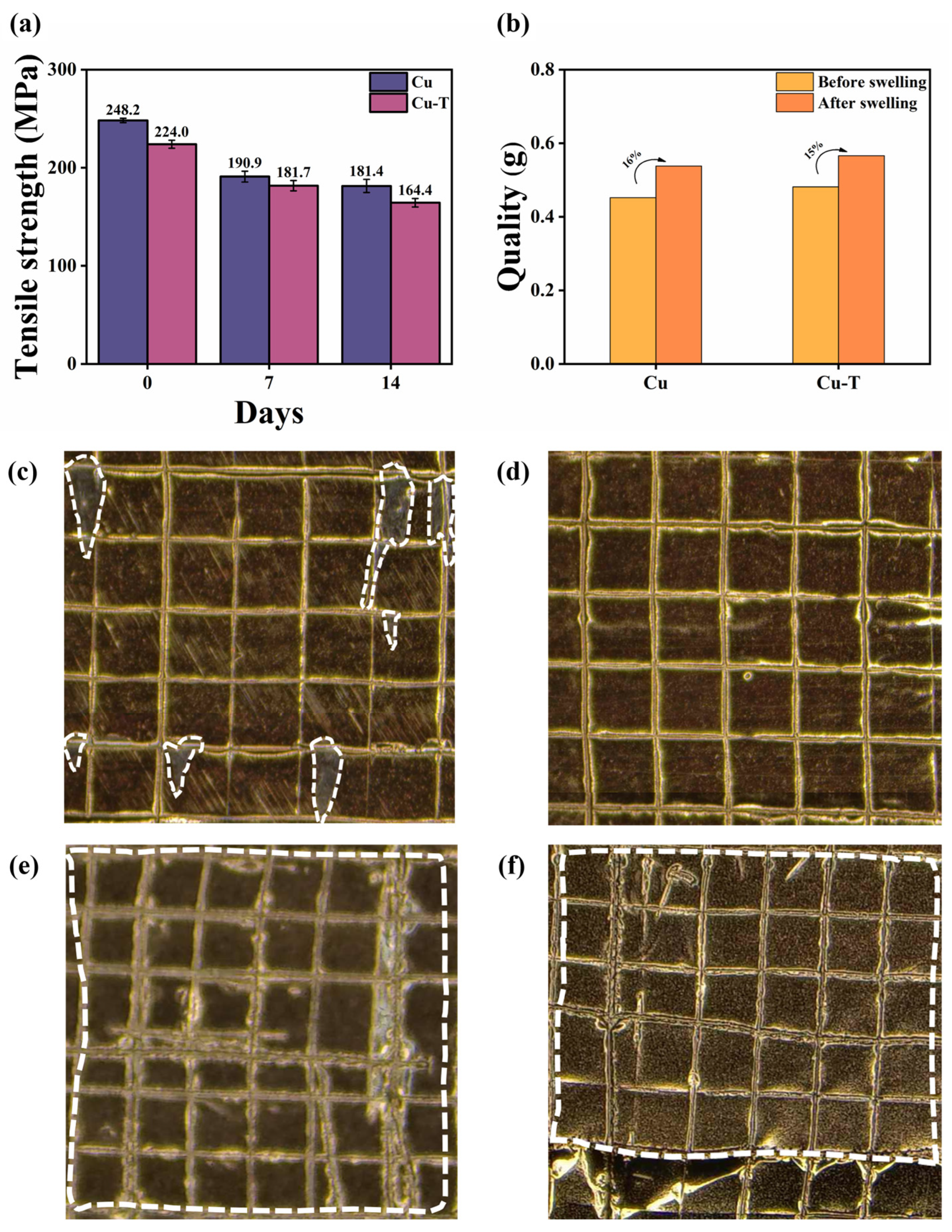
3.1. Morphology and Tensile Properties
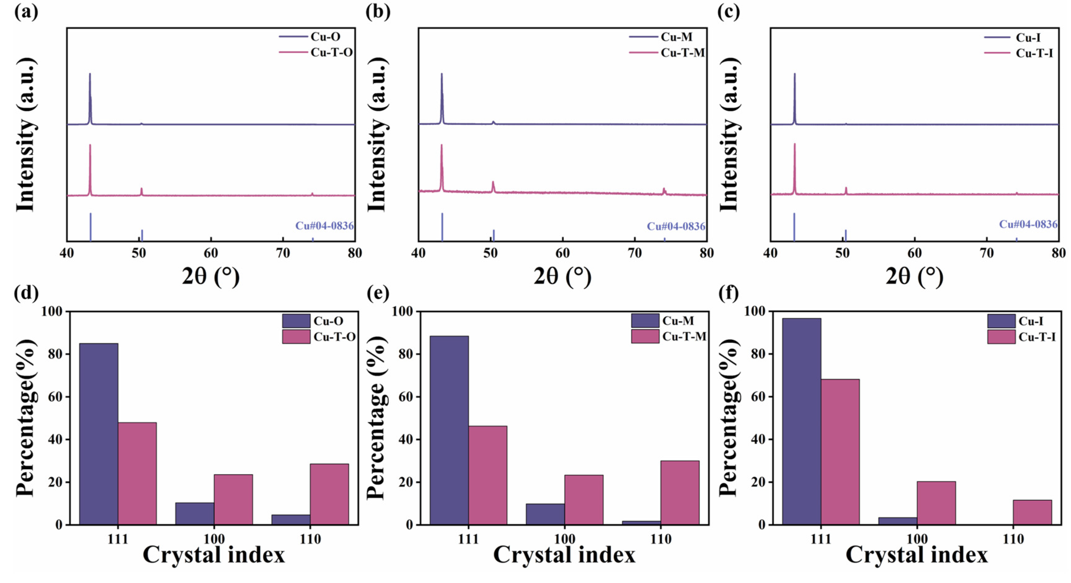
3.2. XRD Analysis
3.3. EBSD Analysis
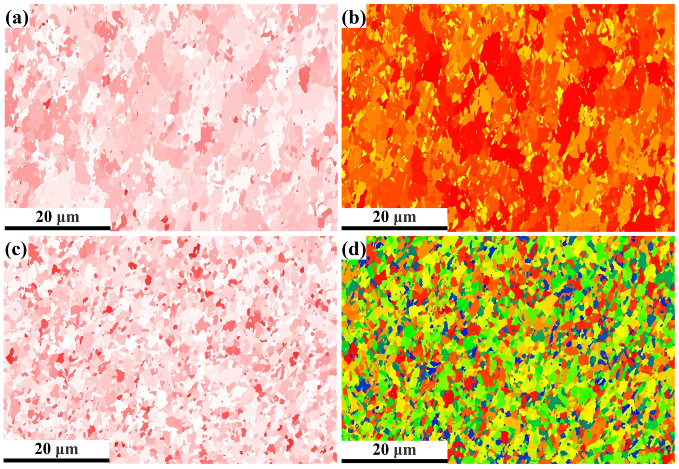
3.3.1. IPF Diagrams and Grain Size Analysis
3.3.2. Recrystallization Diagrams and Size Grain Boundary Diagrams
3.3.3. Schmidt Factor and Taylor Factor
3.4. Mechanical Properties After Immersion in Electrolyte
3.5. Mechanism of Microstructure Evolution
4. Conclusions
Supplementary Materials
Author Contributions
Funding
Data Availability Statement
Conflicts of Interest
References
- Zhang, T.; Yu, J.; Guo, H.; Qi, J.; Che, M.; Hou, M.; Jiao, P.; Zhang, Z.; Yan, Z.; Zhou, L.; et al. Sapiential Battery Systems: Beyond Traditional Electrochemical Energy. Chem. Soc. Rev. 2024, 53, 12043–12097. [Google Scholar] [CrossRef] [PubMed]
- Duan, J.; Tang, X.; Dai, H.; Yang, Y.; Wu, W.; Wei, X.; Huang, Y. Building Safe Lithium-Ion Batteries for Electric Vehicles: A Review. Electrochem. Energy Rev. 2020, 3, 1–42. [Google Scholar] [CrossRef]
- Wang, S.; Shi, J.; Liu, Z.; Xia, Y. Advanced Ether-Based Electrolytes for Lithium-ion Batteries. Adv. Energy Mater. 2024, 14, 2401526. [Google Scholar] [CrossRef]
- Shang, J.; Yu, W.; Wang, L.; Xie, C.; Xu, H.; Wang, W.; Huang, Q.; Zheng, Z. Metallic Glass-Fiber Fabrics: A New Type of Flexible, Super-Lightweight, and 3D Current Collector for Lithium Batteries. Adv. Mater. 2023, 35, e2211748. [Google Scholar] [CrossRef]
- Hao, H.; Tan, R.; Ye, C.; Low, C.T.J. Carbon-coated Current Collectors in Lithium-ion Batteries and Supercapacitors: Materials, Manufacture and Applications. Carbon Energy 2024, 6, e604. [Google Scholar] [CrossRef]
- Du, Y.; Zhang, Y.; Xue, H.; Zuo, P.; Luo, Y.; Xie, J. A Lightweight Carbon-Incorporated Polymer Current Collector for Improving the Performance and Safety of Lithium-Ion Batteries. Carbon 2024, 230, 119622. [Google Scholar] [CrossRef]
- Li, X.; Zhao, M.; Guo, Q.; Zhao, C.; Ding, M.; Zou, D.; Ding, Z.; Zhang, Z.; He, M.; Liu, K.; et al. Single-Crystallization of Electrolytic Copper Foils. J. Mater. Sci. Technol. 2024, 176, 112–118. [Google Scholar] [CrossRef]
- Zhang, J.; Zuo, D.; Pei, X.; Mu, C.; Chen, K.; Chen, Q.; Hou, G.; Tang, Y. Effects of Electrolytic Copper Foil Roughness on Lithium-Ion Battery Performance. Metals 2022, 12, 2110. [Google Scholar] [CrossRef]
- Xu, P.; Lu, W.; Song, K.; Cheng, H.; Hu, H.; Zhu, Q.; Liu, H.; Yang, X. Preparation of Electrodeposited Copper Foils with Ultrahigh Tensile Strength and Elongation: A Functionalized Ionic Liquid as the Unique Additive. Chem. Eng. J. 2024, 484, 149557. [Google Scholar] [CrossRef]
- Ouyang, Z.; Wang, S.; Wang, Y.; Muqaddas, S.; Geng, S.; Yao, Z.; Zhang, X.; Yuan, B.; Zhao, X.; Xu, Q.; et al. An Ultralight Composite Current Collector Enabling High-Energy-Density and High-Rate Anode-Free Lithium Metal Battery. Adv. Mater. 2024, 36, 2407648. [Google Scholar] [CrossRef]
- Dun, X.; Wang, M.; Shi, H.; Xie, J.; Wei, M.; Dai, L.; Jiao, S. Composite Copper Foil Current Collectors with Sandwich Structure for High-Energy Density and Safe Lithium-Ion Batteries. Energy Storage Mater. 2025, 74, 103936. [Google Scholar] [CrossRef]
- Liao, X.; Wang, X.; Yan, C.; Zhang, B.; Ni, Y.; Yuan, H.; Pan, Y.; Pan, J.; Huang, J. Bipolar Current Collectors of Cu/Polymer/Al Composite for Anode-Free Batteries. Adv. Funct. Mater. 2024, 34, 2310925. [Google Scholar] [CrossRef]
- Wu, X.; Chen, S.; Liu, D.; Ye, C.; Si, F.; Zhang, Y.; Yang, Y.; Luo, J.-L.; Fu, X.-Z. Polymer@Cu Composite Foils with Through-Hole Arrays as Lightweight and Flexible Current Collectors for Lithium-Ion Batteries. J. Energy Storage 2023, 74, 109208. [Google Scholar] [CrossRef]
- Liu, Z.; Dong, Y.; Qi, X.; Wang, R.; Zhu, Z.; Yan, C.; Jiao, X.; Li, S.; Qie, L.; Li, J.; et al. Stretchable Separator/Current Collector Composite for Superior Battery Safety. Energy Environ. Sci. 2022, 15, 5313–5323. [Google Scholar] [CrossRef]
- Ye, Y.; Chou, L.-Y.; Liu, Y.; Wang, H.; Lee, H.K.; Huang, W.; Wan, J.; Liu, K.; Zhou, G.; Yang, Y.; et al. Ultralight and Fire-Extinguishing Current Collectors for High-Energy and High-Safety Lithium-Ion Batteries. Nat. Energy 2020, 5, 786–793. [Google Scholar] [CrossRef]
- Yang, C.H.; Yang, S.P.; Huang, B.C.; Lee, C.Y.; Liu, H.C.; Ho, C.E. In-Situ Characterization of the Microstructure Transition of Electroplating Cu during Self-Annealing and Its Effect on the Substrate Warpage. Surf. Coat. Technol. 2019, 364, 383–391. [Google Scholar] [CrossRef]
- Yang, C.-H.; Lee, Y.-W.; Lee, C.-Y.; Lee, P.-T.; Ho, C.-E. Self-Annealing Behavior of Electroplated Cu with Different Brightener Concentrations. J. Electrochem. Soc. 2020, 167, 082514. [Google Scholar] [CrossRef]
- Choi, J.; Hennebert, E.; Flammang, P.; Hwang, D.S. A Sugar–Lectin Rich Interface between Soft Tissue and the Stiff Byssus of Atrina pectinata. Biomater. Sci. 2020, 8, 3751–3759. [Google Scholar] [CrossRef]
- Badrudin, S.I.; Noor, M.M.; Abd Samad, M.I.; Zakaria, N.S.N.; Yunas, J.; Latif, R. Eliminating Surface Cracks in Metal Film-Polymer Substrate for Reliable Flexible Piezoelectric Devices. Eng. Sci. Technol. Int. J. 2024, 50, 101617. [Google Scholar] [CrossRef]
- Peng, Y.; Feng, X.; Xia, J.; You, Z.; Zhang, F.; Chen, Y.; Fan, C.; Hua, J.; Lian, Y.; Shan, Z.; et al. Polymer Based Multi-Layer Al Composite Current Collector Improves Battery Safety. Chem. Eng. J. 2024, 491, 151474. [Google Scholar] [CrossRef]
- Shimizu, M.; Ohnuki, T.; Ogasawara, T.; Banno, T.; Arai, S. Electrodeposited Cu/MWCNT Composite-Film: A Potential Current Collector of Silicon-Based Negative-Electrodes for Li-Ion Batteries. RSC Adv. 2019, 9, 21939–21945. [Google Scholar] [CrossRef] [PubMed]
- Ogata, K.; Kasuya, Y.; Gao, X.; Shibayama, Y.; Takagi, A.; Yonezu, A.; Xu, J. Adhesion Strength of an Active Material Layer/Cu Foil Interface in Silicon-Based Anodes. ACS Appl. Mater. Interfaces 2024, 16, 17692–17700. [Google Scholar] [CrossRef]
- Li, D.; Hu, H.; Chen, B.; Lai, W. Advanced Current Collector Materials for High-Performance Lithium Metal Anodes. Small 2022, 18, 2200010. [Google Scholar] [CrossRef]
- Feng, Y.; Fan, Y.; Zhao, L.; Yu, J.; Liao, Y.; Zhang, T.; Zhang, R.; Zhu, H.; Sun, X.; Hu, Z.; et al. Enhancing Microdomain Consistency in Polymer Electrolytes towards Sustainable Lithium Batteries. Angew. Chem. Int. Ed. 2025, 64, e202417105. [Google Scholar] [CrossRef] [PubMed]
- Schneider, M.; Weiser, M.; Matthey, B.; Herrmann, M. In-Situ Xrd-Investigation of Electrolytic Copper Layer. Appl. Surf. Sci. 2018, 457, 815–820. [Google Scholar] [CrossRef]
- Mao, Z.N.; Gu, R.C.; Liu, F.; Liu, Y.; Liao, X.Z.; Wang, J.T. Effect of Equal Channel Angular Pressing on the Thermal-Annealing-Induced Microstructure and Texture Evolution of Cold-Rolled Copper. Mater. Sci. Eng. A 2016, 674, 186–192. [Google Scholar] [CrossRef]
- Fu, A.; Liu, B.; Liu, B.; Cao, Y.; Wang, J.; Liao, T.; Li, J.; Fang, Q.; Liaw, P.K.; Liu, Y. A Novel Cobalt-Free Oxide Dispersion Strengthened Medium-Entropy Alloy with Outstanding Mechanical Properties and Irradiation Resistance. J. Mater. Sci. Technol. 2023, 152, 190–200. [Google Scholar] [CrossRef]
- Zhang, J.; Chen, H.; Fan, B.; Shan, H.; Chen, Q.; Jiang, C.; Hou, G.; Tang, Y. Study on the Relationship between Crystal Plane Orientation and Strength of Electrolytic Copper Foil. J. Alloys Compd. 2021, 884, 161044. [Google Scholar] [CrossRef]
- Sun, J.; Jiang, T.; Wang, Y.; Guo, S.; Liu, Y. Ultrafine Grained Dual-Phase Martensite/Ferrite Steel Strengthened and Toughened by Lamella Structure. Mater. Sci. Eng. A 2018, 734, 311–317. [Google Scholar] [CrossRef]
- Wang, H.; Guo, J.; Liu, Z. Tensile properties and failure of hybrid fiber reinforced polymer composite laminate with different fiber types, hybrid ratios, and stacking sequences. Polym. Compos. 2025, pc.29561. [Google Scholar] [CrossRef]
- Fan, B.; Hu, J.; Wu, Z.; Zhang, J.; Chen, Q.; Hou, G.; Tang, Y.; Hu, W. Relationship between the Orientation of the (100) Crystal Plane and Elongation in Ultrathin Electrolytic Copper Foils. J. Phys. Chem. C 2024, 128, 5759–5767. [Google Scholar] [CrossRef]
- Li, R.; Xiao, Z.; Li, Z.; Meng, X.; Wang, X. Work Hardening Behavior and Microstructure Evolution of a Cu-Ti-Cr-Mg Alloy during Room Temperature and Cryogenic Rolling. Materials 2023, 16, 424. [Google Scholar] [CrossRef]
- Lee, C.; Kim, Y.; Kim, R.; Yoo, B.; Kim, J.-K. Evolution of Microstructures and Mechanical Properties of Ultrahigh Strength, Pure Electrodeposited Cu during Self-Annealing. J. Alloys Compd. 2020, 846, 156488. [Google Scholar] [CrossRef]
- Cao, X.; Zhu, Q.; Liu, Y.; Song, K.; Jia, S.; Liu, H.; Lu, W.; He, M.; Feng, Q. Grain Refinement and Texture Regulation Mechanism of Spin-Formed Commercially Pure Titanium Cathode for Electrolytic Copper Foil. J. Mater. Res. Technol. 2024, 29, 2350–2362. [Google Scholar] [CrossRef]
- Liang, C.; Wang, N.; Chen, Y.; Jiang, C.; Wu, G.; Zhao, Q.; Zhu, L.; Luo, J. Transition of Low and High-Angle Grain Boundaries during Strain Rate-Induced Dislocation Storage and Annihilation. Mater. Charact. 2023, 205, 113284. [Google Scholar] [CrossRef]
- Guo, B.; Gao, H.; Kong, C.; Wang, Z.; Cui, H.; Yu, H. Transverse Texture Weakening and Anisotropy Improvement of Ti-6Al-4V Alloy Sheet via Asymmetric Rolling and Static Recrystallization Annealing. J. Alloys Compd. 2025, 1010, 177507. [Google Scholar] [CrossRef]
- Zhu, Z.; Ma, X.; Wang, C.; Mi, G. Altering Morphological, Crystalline and Compositional Features in 316 L Laser-MIG Weldments with an External Magnetic Field. Mater. Des. 2020, 196, 109156. [Google Scholar] [CrossRef]
- Huang, L.; Dong, X.; Wei, K.; Zhang, T.; Zhang, S.; Xu, Y.; Wei, K. In-Situ Investigation of Coordinated Deformation Behavior of Ti-6242S Alloy with Duplex Microstructure. Mater. Today Commun. 2024, 40, 109813. [Google Scholar] [CrossRef]
- Xia, Y.; Zhang, Y.; Wu, T.; Wang, N.; Ran, R.; Wang, Y.; Fang, F.; Wang, G. Deformation Twinning Caused by Warm Rolling and Secondary Recrystallization in Twin-Roll Strip Casting Fe81Ga19 Alloy. J. Alloys Compd. 2022, 922, 166039. [Google Scholar] [CrossRef]
- Cho, C.-H.; Kim, D.-O.; Son, K.; Park, H.-S. Relationship between Hot Workability and Texture Evolution in an Al–Zn–Mg–Cu Alloy under Hot Compressive Stress Mode. J. Mater. Sci. 2023, 58, 16537–16549. [Google Scholar] [CrossRef]
- Sarkar, A.; Sanyal, S.; Bandyopadhyay, T.K.; Mandal, S. Implications of Microstructure, Taylor Factor Distribution and Texture on Tensile Properties in a Ti-Added Fe-Mn-Al-Si-C Steel. Mater. Sci. Eng. A 2019, 767, 138402. [Google Scholar] [CrossRef]
- Qin, G.; Zhang, J.; Chen, H.; Li, H.; Hu, J.; Chen, Q.; Hou, G.; Tang, Y. Lithium Difluoro(Oxalate)Borate as Electrolyte Additive to Form Uniform, Stable and LiF-Rich Solid Electrolyte Interphase for High Performance Lithium Ion Batteries. Surf. Interfaces 2024, 48, 104297. [Google Scholar] [CrossRef]
- Zhang, X.; Wang, A.; Lv, R.; Luo, J. A Corrosion-Resistant Current Collector for Lithium Metal Anodes. Energy Storage Mater. 2019, 18, 199–204. [Google Scholar] [CrossRef]
- Lin, H.-E.; Tran, D.-P.; Lin, G.-H.; Chuang, H.-J.; Chen, C. Effects of Residual Stress and Microstructure on Extremely Anisotropic Grain Growth in Nanotwinned Cu Films. Mater. Charact. 2024, 211, 113891. [Google Scholar] [CrossRef]
- Murray, C.E.; Treger, M.; Noyan, I.C.; Rosenberg, R. Evolution of Strain Energy During Recrystallization of Plated Cu Films. IEEE Trans. Device Mater. Reliab. 2016, 16, 440–445. [Google Scholar] [CrossRef]
- Carel, R.; Thompson, C.V.; Frost, H.J. Computer Simulation of Strain Energy Effects vs Surface and Interface Energy Effects on Grain Growth in Thin Films. Acta Mater. 1996, 44, 2479–2494. [Google Scholar] [CrossRef]
- Du, K.; Zhang, Y.; Zhao, G.; Huang, T.; Liu, L.; Li, J.; Wang, X.; Zhang, Z. Effect of Grain Orientation and Precipitates on the Superelasticity of Fe–Ni–Co–Al Polycrystalline Alloys. Mater. Sci. Eng. A 2024, 890, 145858. [Google Scholar] [CrossRef]
- Jung, G.; Kim, S.; Eom, J.; Song, I.Y.; Lee, J.; Cho, S.-K.; Lee, W.-E.; Heo, K.; Cho, T.-Y.; Yun, H. Substrate-dependent structural evolution during the oxidation of SiNx thin films. J. Mater Sci. 2024, 59, 10432–10443. [Google Scholar] [CrossRef]
- Zhou, X.; Liu, S.; Amna, S.; Min, C.; Pei, X.; Liu, S.; Yin, Y.; Song, K.; Xu, Z. Construction of nanocomposite interphase with controllable thickness to relieve stress concentration and boost stress transfer from carbon fiber/epoxy resin interface. Chem. Eng. J. 2025, 505, 159542. [Google Scholar] [CrossRef]
- Wang, L.; Bai, Z.; Sun, W.; Du, L.; Peng, X.; Xiao, Y.; Zhang, J.; Jia, Y.; Du, S.; Cai, H.; et al. Effect of Low Temperature Annealing on Microstructure and Properties of Copper Foil. Mater. Today Commun. 2023, 36, 106617. [Google Scholar] [CrossRef]


Disclaimer/Publisher’s Note: The statements, opinions and data contained in all publications are solely those of the individual author(s) and contributor(s) and not of MDPI and/or the editor(s). MDPI and/or the editor(s) disclaim responsibility for any injury to people or property resulting from any ideas, methods, instructions or products referred to in the content. |
© 2025 by the authors. Licensee MDPI, Basel, Switzerland. This article is an open access article distributed under the terms and conditions of the Creative Commons Attribution (CC BY) license (https://creativecommons.org/licenses/by/4.0/).
Share and Cite
Yan, Y.; Chen, H.; Li, H.; Hu, J.; Xue, Z.; Zhang, J.; Chen, Q.; Hou, G.; Tang, Y. Study on Mechanical Properties and Microstructural Evolution of Composite Copper Foils Following Long-Term Storage. Batteries 2025, 11, 173. https://doi.org/10.3390/batteries11050173
Yan Y, Chen H, Li H, Hu J, Xue Z, Zhang J, Chen Q, Hou G, Tang Y. Study on Mechanical Properties and Microstructural Evolution of Composite Copper Foils Following Long-Term Storage. Batteries. 2025; 11(5):173. https://doi.org/10.3390/batteries11050173
Chicago/Turabian StyleYan, Yujie, Haibo Chen, Hang Li, Jing Hu, Ziye Xue, Jianli Zhang, Qiang Chen, Guangya Hou, and Yiping Tang. 2025. "Study on Mechanical Properties and Microstructural Evolution of Composite Copper Foils Following Long-Term Storage" Batteries 11, no. 5: 173. https://doi.org/10.3390/batteries11050173
APA StyleYan, Y., Chen, H., Li, H., Hu, J., Xue, Z., Zhang, J., Chen, Q., Hou, G., & Tang, Y. (2025). Study on Mechanical Properties and Microstructural Evolution of Composite Copper Foils Following Long-Term Storage. Batteries, 11(5), 173. https://doi.org/10.3390/batteries11050173