Abstract
For lithium iron phosphate batteries (LFP) in aerospace applications, impedance spectroscopy is applicable in the flat region of the voltage-charge curve. The frequency-dependent pseudocapacitance at 0.15 Hz is presented as useful state-of-charge (SOC) and state-of-health (SOH) indicator. For the same battery type, the prediction error of pseudocapacitance is better than 1% for a quadratic calibration curve, and less than 36% for a linear model. An approximately linear correlation between pseudocapacitance and Ah battery capacity is observed as long as overcharge and deep discharge are avoided. We verify the impedance method in comparison to the classical constant-current discharge measurements. In the case of five examined lithium-ion chemistries, the linear trend of impedance and SOC is lost if the slope of the discharge voltage curve versus SOC changes. With nickel manganese cobalt (NMC), high impedance modulus correlates with high SOC above 70%.
1. Introduction
Because of the high demands on the reliability of emergency power supplies in aircrafts, planned take-offs can be delayed. After parking for a long time without a power supply, the state-of-charge (SOC) of aircraft batteries drops because of self-discharge. Indeed, capacity determination and recharging of a 2-Ah battery using the constant current discharge method and other diagnosis measures take roughly 1.5 to 2 h according to the state-of-the-art in air traffic. In the aviation sector, fast charging is only permitted in an emergency. As an expensive precaution, freshly charged batteries must be kept ready. Short maintenance intervals require a reliable method for fast battery diagnosis that reflects at least the upper SOC range.
Based on our earlier work [,] on SOC determination using electrochemical impedance spectroscopy [,,,], we have investigated various chemistries of lithium ion batteries under normal ambient conditions and overcharging. We tried to find early indicators for thermal overload and critical overcharge in the impedance spectrum of “healthy” batteries. This work focuses on lithium iron phosphate (LFP) [,], which is less sensitive to thermal runaway and fire than cobalt-based systems (LCO, NMC, NCA) and manganese spinel (LMO). For emergency power supplies in aircrafts, LFP combines a couple of positive properties such as inherent safety on thermal runaway in the event of overcharging and overheating. Lithium ions migrate through the linear channels of the olivine lattice Li1-xFePO4. The material is readily available, strategically uncritical and almost not harmful. Unfortunately, the cell voltage of 3.6 V is lower than the 4.2 V of most other lithium technologies. The capacity is prone to degradation if long periods of time are operated either in the upper or lower potential range and at low temperatures [,,].
1.1. Battery State Indicators
Rated capacity [] is the electric charge QN that is stored by a new battery under defined conditions. The state-of-charge (SOC) [] describes the relationship between the currently available capacity, Q(t) = α·β·QN, and the total capacity Q0 at the previous full charge. α = 1 (100% SOC) represents the full charge, and α = 0 (0% SOC) is the empty battery. However, lithium-ion batteries are not allowed to be discharged below the cut-off voltage.
The state-of-health (SOH) [] considers the capacity loss using the remaining capacity in aged batteries Q0 in relation to the nominal capacity QN of the new battery.
The state-of-function (SOF) reflects the deterioration in performance (power fading).
For SOC determination [,], voltage measurements have been common practice since the 1930s. Accuracy is poor for relatively flat voltage curves, as shown in Figure 1. Hung et al. [] determined the SOC by the help of a line, which is defined by the dynamic resistance ΔU/ΔI during incremental charging and discharging.
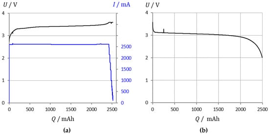
Figure 1.
Lithium iron phosphate battery (LithiumWerks 2.6 Ah): (a) Charge at constant current and constant voltage. (b) Flat discharge profile. EIS measurements were performed from 100% to 30% state-of-charge (SOC) in 2% steps.
Impedance spectroscopy [], coulomb counting [], bookkeeping methods [,], and look-up tables [] have been established since the mid-1970s, and have been supplemented in the past decade by fuzzy logic, Kalman filters, learning algorithms, predictive methods [], and the analysis of relaxation times []. At present, there is still no universal method of precisely determining the usable capacity of a battery without completely discharging the battery.
1.2. State-of-Health Indicators
Impedance spectroscopy displays changes in the resistance and capacitance of a battery without destroying the cell. Reliable methods of health assessment and fault diagnosis such as lithium plating, short circuit, overcharge, and deep discharge require a deep understanding of broadband impedance and modeling, as the impedance spectrum is strongly influenced by battery states and operating conditions [], See Section 3.7.
The impedance at a certain frequency is useful in diagnosing the thermal runaway. The electrolyte resistance, RS = Re Z(ω → ∞), the intersection on the real axis, does not decrease strictly linearly with rising temperature. Eddahech et al. [] suggest the real part at 0.1 Hz for the estimation of remaining life. As well, Galeotti et al. [] correlate the available capacity and the SOH with the ohmic resistance. Howey et al. [] evaluate the range between 1 Hz and 2 kHz with both multisine and noise excitation signals. M. Spielbauer et al. [] studied the mechanical deformations using computer tomography; internal short circuits cause a drop in ohmic resistance at frequencies above 100 Hz.
Srinivasan et al. [] use the abrupt rise of the phase shift part of cell impedance as a quick indicator, seconds before the upcoming cell venting and the thermal runaway some minutes later; the phase shift φ depends only slightly on the battery size and Ah-capacity. The cell voltage remains constant until after the cell has been vented.
The current state-of-the-art does not provide a universal and rapid method of determining the state-of-health of a battery without carefully examining the degradation of hundreds of full charge/discharge cycles. This work tries a novel approach in order to link the actual battery charge with a quickly measurable impedance quantity.
1.3. Pseudocapacitance and Pseudocharge
Each impedance value consists of a real part (ohmic resistance) and an imaginary part (reactance). The real part of impedance (resistance R = Re Z) and the modulus |Z(ω)| reflect the electrolyte and the kinetic inhibitions of the electrode processes. We add the pseudocapacitance C(ω) [,] according to Equation (4), as a unique measure for the activity of the electrode/electrolyte interface. As a qualitative indicator of the battery’s state-of-charge, this quantity depends mainly on the imaginary part of impedance (reactance, X = Im Z).
At high frequencies (ω → ∞), pseudocapacitance tends to the geometric double-layer capacitance CS of the interface. The ohmic resistance of the electrolyte solution, RS = Re Z(ω → ∞), is found as the intersection of the complex plane plot with the real axis. The approximation in Equation (5) holds for high frequencies, when the polarization resistance of the battery is negligible []. This is true when the DC resistance of the battery is not much greater than the electrolyte resistance RS.
The pseudocapacitance C(ω) can be calculated for individual data points in all areas of the impedance spectrum. The differently fast processes at the electrode-electrolyte interface appear in certain frequency ranges. The electrolytic double layer, absorbed ions on the electrode surface, and ions intercalating into the porous electrodes cause the capacitive properties of cell impedance. Depending on the frequency range, pseudocapacitance according to Equation (4) can be interpreted as double-layer capacitance (at high and medium frequencies) or as capacitance that is involved in ion adsorption and mass transport phenomena (at low frequencies). Common equivalent circuits for batteries describe this mass transport capacitance by transmission line networks that contain resistances and capacitances or the so-called Warburg impedance. This work dispenses with the curve fitting to equivalent circuit diagrams. The diagram of frequency-dependent capacitance C(ω) versus resistance R is useful for the direct comparison of storage batteries (see Section 3).
Since the impedance method does not provide Ah-capacities, we introduce the pseudocharge Q(ω) as a measure for the available electric charge of the battery. U(t) is the cell voltage at time t of the impedance measurement.
Note that there is a scaling factor between the true electrical charge (battery capacity) and the frequency-dependent pseudocharge Q(ω). See Section 3.3.
2. Experimental Setup
This lithium-ion batteries of the LFP type of different manufacturers were investigated in the course of long-time tests under real conditions as in the airplane.
- A.
- VoltSolar: 18,650 type, 3.2 V, 1.4–1.5 Ah, charge max. 3.65 V, cut-off voltage 2.0 V.
- B.
- Sony: US18650FT cylindrical, 3.2 V, 1.05–1.1 Ah,
- C.
- LithiumWerks (formerly A123) 26,650 cell, ANR26650M1B: 3.3 V, 2.6 Ah.
Different cell chemistries and manufacturers were compared (see Table 1).

Table 1.
Lithium-ion batteries in this study. Nominal data according to manufacturers’ data sheets. Approximate slope of the voltage-SOC curve (see Section 3.6). Cubic and linear approximation of the capacitance-capacity curve (see Section 3.2).
2.1. Test Procedure
In order to find the desired correlation between pseudocapacitance and real remaining battery capacity (SOC), the fully charged battery was discharged in 2% steps using constant current. After a rest period to set a stationary cell voltage, the impedance spectrum was measured.
- Capacity determination by coulomb-counting: Each cell was first charged at 1 C rate (CC) to the upper cutoff voltage, then at constant voltage (CV) until the current dropped below 0.1 A. The discharge took place at 25 °C and 1 C rate under a constant current load until the cut-off voltage was reached. Q is the withdrawn electrical charge. Then the battery was recharged as above.
- Impedance measurements were taken 20 min after each constant-current discharge step, from SOC 100%, 98%, 96%, down to 30%. The VoltSolar cell was tested down to 50% SOC. The EIS measurement took 80 s for six values per frequency decade in the frequency range from 1 kHz to 0.1 Hz. The measuring arrangement is schematically shown in Figure 2.
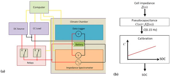 Figure 2. (a) Schematic measurement setup: Impedance spectrometer BIM2 (BRS GmbH, Stuttgart, Germany), data logger (Agilent 34972A), electronic load (ET Systems ELP/DCM 9712C), DC power source (Elektro-Automatik EA-PS 2342-10B), and relay box reside in a climatic chamber (Vötsch VT7021). Data acquisition: Labview. (b) Basic model assumption and data evaluation.
2.2. Measurement Parameters
The battery is periodically charged and discharged by a small AC excitation signal that is superimposed on the almost constant cell voltage, so that no net charge or discharge of the cell occurs. The AC amplitude must be small in order to meet the criterion of small-signal excitation, but large enough to find a compromise with the duration of the measurement periods. An adequate integration time of 8 to 10 cycles was chosen in order to obtain smooth impedance spectra. The current flowing through the cell was negligible (20 mA AC, <10 mA DC). It would take hundreds of impedance measurements or several hours to significantly discharge the battery. The cell voltage did not change by more than 0.05 V during the impedance measurement according to the data logger.
The equilibration time after setting the SOC (2% step) is important to avoid outliers. In the event of a non-equilibrium, the battery discharges against the measurement device, and the individual cells in a battery pack interfere with each other. Measurement time must be invested if the data points scatter. The frequency point at 0.15 Hz takes roughly a minute (6.7 s times ten cycles) for the measurement, which is still fast compared to a 1 C constant current discharge profile (1 h) and the subsequent recharging of a 2 Ah battery (fast CC and slow CV charging takes 1.5 h according to the above Figure 1a). This procedure seems appropriate because the aviation batteries are measured after a period of storage. That is, the impedance measurement can be started without delay.
3. Results and Discussion
3.1. Frequency Response of Pseudocapacitance
The Nyquist diagram in Figure 3 can be regarded as composed of two views [], which show the frequency response of resistance R = Re Z and reactance X = Im Z.
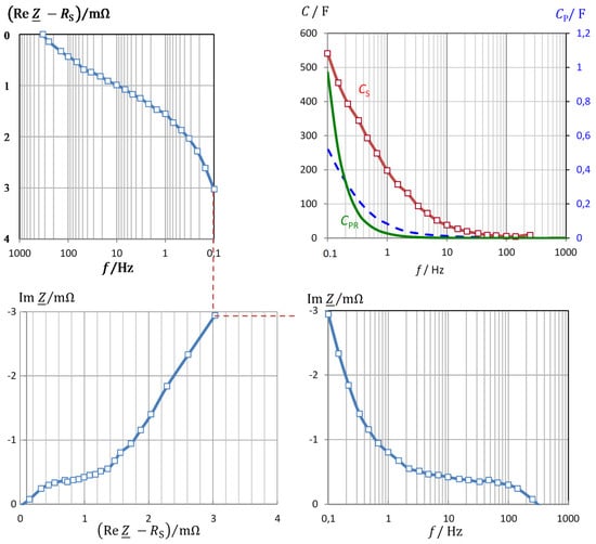
Figure 3.
Frequency response of impedance of the cell C LithiumWerks (2.6 Ah). The electrolyte resistance RS = R(333 Hz) was subtracted. Capacitance versus frequency: including leakage: , and corrected by the electrolyte resistance: according to Equation (4). Imaginary part of impedance: X = Im Z(ω).
Some parts of the spectra show more or less linear regions. The data of the other tested cells are comparable and do not provide any additional information at this stage of evaluation. The different courses of the Nyquist plot for the same battery chemistry raise the urgent question of which physical variable can be meaningfully evaluated for SOC monitoring. The Nyquist diagrams in Figure 4 show that the state-of-charge affects both the real part and the imaginary part of impedance. Resistance drops and capacitance increases with SOC. Unlike the 18,650 cells, the 26,650 design exhibits significant inductance, i.e., positive imaginary parts occur at high frequencies above 333 Hz. The stored residual electric charge Q (capacity) of a battery is expected to correlate with the pseudocapacitance according to the definition C = dQ/dU. The pseudocapacitance according to Equation (4) is coined by the reactance, therefore the imaginary part of impedance is expected to show the state-of-charge as well. What is needed, however, is a quantity that maps the state-of-charge as linearly as possible over a large measuring range. Pseudocapacitance C(ω) combines all information about resistance, reactance, and frequency. The electrolyte resistance, which is of little use for SOC determination, is subtracted from the measured real parts. The pseudocapacitance corrected in this way is then directly related to the electric charge.
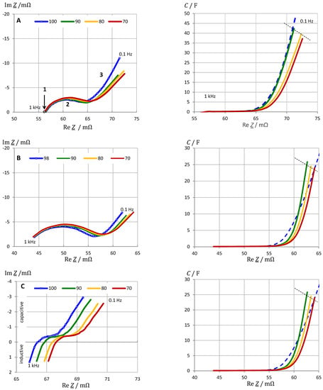
Figure 4.
SOC monitoring by impedance spectroscopy of lithium iron phosphate (LFP) batteries at rest: (A) VoltSolar (1.5 Ah), (B) Sony (1.1 Ah), (C) LithiumWerks (2.6 Ah). Pseudocapacitance C(ω) according to Equation (4), where the electrolyte resistance RS = R(333 Hz) was subtracted from the real parts of impedance. Frequency range 0.1 Hz to 1 kHz. Regions: 1 Electrolyte resistance, 2 Charge transfer, 3 mass transport.
3.2. Correlation of Pseudocapacitance and Battery Capacity
In the following the significance of the pseudocapacitance C(ω) for the actual electric charge Q and energy content of the battery is shown. The linear relationship between the pseudocapacitance and the SOC in Figure 5 is best at a frequency around 0.15 Hz. This means that the capacitance does not necessarily have to be measured down to extremely low frequencies. The chosen frequency of 0.15 Hz covers a part of the mass transport limited charge transfer reaction that is proportional to the genuine charge storage process by lithium ion intercalation at very low frequencies.
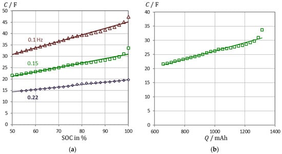
Figure 5.
(a) State-of-charge monitoring of a VoltSolar LFP cell (1.5 Ah) using capacitance at selected frequencies. Example: C/F = 0.1925·SOC + 11.64 at 0.15 Hz. SOC = Q/Q0 is based on Ah counting. EIS measurements were performed from 100% to 50% SOC in 2% steps. (b) Linear relationship between capacitance and battery capacity: C = 14.65⋅Q + 11.64 (fit quality: 95.3%).
We conclude that pseudocapacitance reflects the state-of-charge better than any other quantity obtained from impedance spectroscopy. The linearity between pseudocapacitance and electric charge is improved, when the electrolyte resistance RS is corrected in Equation (6). Overcharging disrupts the linear trend between capacity and SOC. The abrupt increase in capacity at SOC = 1, however, could be used to indicate that the battery is fully charged before there is a risk of overcharging.
3.3. Verification and Validation of the Pseudocapacitance Model
The correlation of pseudocapacitance C at 0.15 Hz and state-of-charge (SOC) was verified by impedance measurements on three different LithiumWerks 2.6 Ah batteries. The “true” SOC values were determined by Ah counting. Each battery was tested three times in a row in the SOC range from 100% to 30% in 2% steps. Analogous to Figure 5a, congruent C(SOC) curves were obtained with a repeatability of about 2%.
Three batteries of the same type were tested on different days (see Table 2). The pseudocapacitance values had a precision of better than 12% for each SOC value. According to the David test, the data obey a normal distribution. A linear model is a good approximation, having a regression coefficient of 98.6%. According to the Mandel test, however, a square model is better (R2 = 99.3%). The linear trend gets better if the SOC range is considered up to 98% (instead of 100%), because overcharge phenomena occur at full charge. The prediction error is less than 1% for the quadratic model (average ± 0.4%), and less than 36% for the linear model.

Table 2.
Validation of the linear correlation between state-of-charge and pseudocapacitance for three lithium-iron phosphate batteries of the same manufacturer.
If the SOC determined by Ah counting is assumed to be the “true” value, the model predicts SOC values that are good enough to estimate whether a battery of the same type and manufacturer is full, three quarter full, half-full, quarter full, or empty.
3.4. Properties of Pseudocharge
We introduce the pseudocharge Q(ω) = C(ω)⋅U(t), so that the capacitance C(ω) obtained by impedance spectroscopy can be better compared with the actual electrical charge Q (battery capacity). This quantity includes the instantaneous cell voltage U(t), which for itself is not a precise SOC indicator (see Figure 6a). The voltage exhibits several plateaus while the pseudocharge is fairly linear with respect to the SOC. Furthermore, the pseudocharge can be normalized to the fully charged battery, so that a SOC scale between 0% and 100% is obtained.
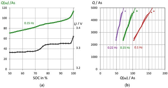
Figure 6.
VoltSolar LFP battery. (a) Pseudocharge Q(0.15 Hz) = C(0.15 Hz)⋅U and cell voltage U versus the “true” state-of-charge Q measured by Ah counting. (b) Linear correlation between pseudocharge Q(ω) and “true” battery capacity at different discharge states. Example: Q/As = 66.92⋅Q(0.15 Hz) − 2226. LPF batteries from different manufacturers show qualitatively the same results.
There is a scaling factor between the real electric charge and the pseudocharge which in practice must be determined by calibration (see Section 3.3). Nevertheless, the pseudocharge (in As) at a selected frequency is a linear function of “true” battery capacity (see Figure 6b). At high state-of-charge, overcharge effects cause a slight deviation from the generally linear relationship. The linearity is coined by the steps in the voltage-capacity curve.
Example: The fully charged LithiumWerks battery (2.6 Ah, 3.35 V) exhibits a pseudocharge of: Q(0.15 Hz) = C U = 201.6 F·3.35 F = 675.4 As = 0.188 Ah. Therefore, there is a correction factor of Q = 13.9⋅Q(0.15 Hz), which is required to compare Ah counting with the impedance method. The “true” energy of W = 3.35 V⋅2.6 Ah = 8.7 Wh or 9360 Ws requires the correction: W = 4.1⋅Q(0.15 Hz).
3.5. Conversion of Impedance Data to Energy and Power
Pseudocharge Q(0.15 Hz) allows to calculate an equivalent for the stored energy W and the specific energy of the battery (energy divided by mass), as shown in Figure 7a.
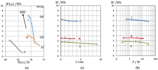
Figure 7.
(a) Energy W of three types of LFP cells determined by the pseudocharge Q = C U at 0.15 Hz against the real part of impedance (ohmic resistance) at 0.15 Hz. A VoltSolar 3.2 V/1.4 Ah, B Sony 3.2 V/1.1 Ah, C LithiumWerks 3.3 V/2.6 Ah. (b) For comparison: Peukert diagram of true energy versus C rate, (c) Ragone plot: true energy versus power (measured by current and voltage).
To prove the quality of the impedance method, we compared the pseudoenergy with data from conventional electrical stress tests, in which LFP cells were discharged at different currents. The available energy is compiled in the Peukert plot against the applied C rate (Figure 7b), and in the Ragone plot (Figure 7c) against the withdrawn electric power.
With a high current (C rate) and high discharge power, the battery will be exhausted in less time. As can be seen, the energy agrees very well with the results using impedance data, at least on the order of magnitude.
3.6. Impact of Cell Chemistry
The determination of a generalized absolute state-of-charge is complicated by the various cell chemistries of lithium-ion batteries. Therefore, we compared different lithium-ion batteries as compiled in Table 1 to demonstrate the quality of capacitance C(ω) for SOC monitoring. The impedance spectra (Figure 8) show three regions:
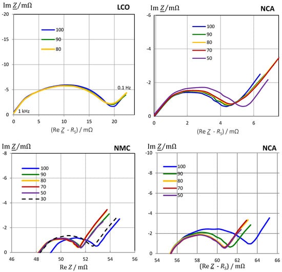
Figure 8.
Impedance spectra of different lithium-ion chemistries at rest in defined charge states. NMC as measured to show the influence of SOC on electrolyte resistance. LCO and NCA are shifted on the real axis to the electrolyte resistance of SOC = 1. Frequency range 0.1 Hz to 1 kHz.
- Electrolyte and solid-electrolyte interface (SEI) at high frequencies;
- Charge-transfer at medium frequencies;
- Pore diffusion and intercalation at frequencies below 0.01 Hz.
It is useful to subtract the electrolyte resistance (intersection with the real axis) to create a set of congruent curves, which are independent of contact and cable errors.
The frequency is chosen below 10 Hz. With the corrected real part, the modulus |Z(ω)| and the pseudocapacitance, C(ω) = –Im Z/(ω |Z|2), are calculated. The shape of diffusion impedance at low frequencies depends on whether the lithium-ion are mobile in linear channels (Li1-xFePO4), in areas of the layer lattice (Li1-xCoO2, NMC) or in the void spaces of a spinel (Li1-xMn2O4, LMO).
The qualitative impact of the state-of-charge on the impedance spectrum is compiled in Table 3. The Nyquist diagram of the LCO chemistry makes SOC monitoring difficult because the curves are more or less congruent; the real part of impedance (resistance) at any frequency does not allow a reliable SOC determination. Better than the ohmic resistance, the imaginary part Im Z(ω) and pseudocapacitance C(ω) at low frequencies reflect the state-of-charge, although there is no clear trend between SOC and reactance. At most in the SOC range from 80% to 100%, a high capacitance shows a high state-of-charge.

Table 3.
Qualitative changes in the impedance spectrum in different state-of-charge areas: R resistance of the high-frequency arc, X reactance at 0.1 Hz, C capacitance at 0.1 Hz.
In the case of medium and low state-of-charge, an illogical order occurs that pretends a higher SOC. It makes the evaluation easier if the frequency response of the imaginary part is related to the fully charged battery. However, this relative quantity, Im Z(SOC)/Im Z(SOC = 1), misrepresents overcharging and aging phenomena.
LMO chemistry shows a slight increase of impedance |Z(ω)|with SOC in the linear range of the flat voltage-charge curve. Below SOC = 0.5, impedance increases strongly.
With NMC and NCA chemistry, high impedance |Z| (in F) and high residual battery capacity (in Ah) correlate for high state-of-charge above 70%. At low SOC, the resistance and capacitance increase. Pseudocapacitance is not clearly a linear function of SOC.
Figure 9 demonstrates that pseudocapacitance reflects the state-of-charge in the correct order of magnitude. Unfortunately, the connex is not linear. Rather two linear regions can be distinguished from SOC = 60% to 100% for all battery chemistries, which can be fitted by a 3rd order polynomial (coefficients see Table 1). The linearity between impedance and SOC holds as long as the slope of the discharge curve ΔU/ΔSOC does not change. This is not surprising, because the impedance represents the slope of the current–voltage curve, |Z| = dU/dI. The steeper the voltage-charge curve, the more resistance and reactance increase when the battery is depleted.
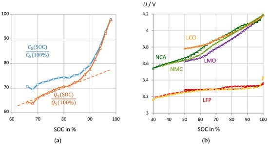
Figure 9.
(a) NMC battery #8: Normalized pseudocapacitance and pseudocharge at 0.1 Hz (reference: 589 F and 2470 As at SOC = 100%) versus “true” SOC from Ah counting. (b) Cell voltage of different cell chemistries versus state-of-charge from Ah counting. Batteries under test see Table 1.
The linear relationship between the state-of-charge (SOC) and the pseudocapacitance C from impedance spectroscopy can be qualitatively understood by the following dependencies. Q0 is the capacity of the fully charged battery, which is determined by Ah counting.
Equation (10) describes that the pseudocapacitance for all battery chemistries depends directly on the SOC, although the linearity may be disturbed by individual steps in the voltage-charge curve. Equation (11) states that the slope of the voltage-SOC curve depends on the kinetic inhibitions (impedance |Z|) of the cell reaction.
3.7. Impact of Aging
This section is intended to show briefly that the proposed pseudocapacitance can correctly reflect the state-of-health of a battery even if the shape of the impedance spectra changes significantly during cycle aging. With aging and progressive SEI formation, the electrolyte resistance at high frequencies becomes larger and larger until two arcs become visible in the impedance spectrum (Figure 10). The internal resistance increases until the end of service life is reached. The electrolyte resistance is not a good SOH indicator, because the passive layer formation in some new batteries leads to an apparent improvement of conductivity during the first charge-discharge cycles until the gradual deterioration follows. For combined SOC and SOH measurements, the pseudocapacitance is still appropriate. As shown above, it is useful to normalize C(ω) to the fully charged battery (SOC = 1) or the new battery (SOH = 1).
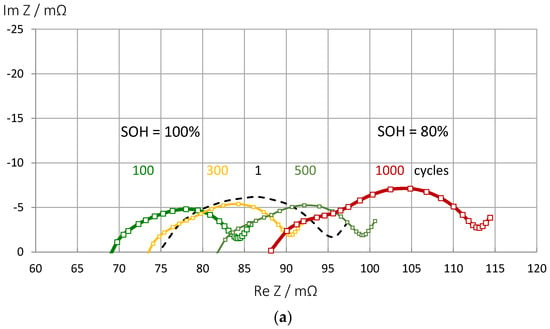
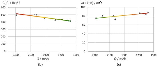
Figure 10.
Aging of an LCO battery at the same state-of-charge (Panasonic UR18650 FK). (a) Impedance spectra of fully charged batteries during aging by a thousand charge-discharge cycles. (b) Pseudocapacitance correlates linearly with the actual battery capacity determined by Ah counting: C = 141⋅Q + 191. Fit quality 0.92. (c) Increase of electrolyte resistance in time.
4. Conclusions
Prior art methods for SOC monitoring suffer from some specific drawbacks: In order to reliably determine the actual remaining battery capacity at a certain point in time, an Ampere hour counting must be carried out during a complete discharge. The cell voltage is an uncertain measure of the “true” electric charge. So far, there is no general and comprehensive model or equivalent circuit that is able to display and predict the state-of-charge and state-of-health of a battery in all system states over the entire service life of a battery.
The empirical concept of pseudocapacitance might overcome some of the shortcomings, albeit new challenges arise. There is a significant linear correlation between pseudocapacitance and remaining capacity for the main types of lithium-ion batteries. Our approach does not require specific model assumptions in advance, such as predefined equivalent circuits or numerical simulations, which are often unclear and complicate the system analysis during the operation.
The pseudocapacitance reacts to electrodes that change over time and signs of aging. However, the proposed method is not as sensitive as the Ah counting. For batteries of the same type and manufacturer the SOC forecast quality is about 1 percentage point based on a quadratic calibration curve (C versus SOC). The method is suitable for high and medium charge states. The SOC detection using pseudocapacitance works best when the current–voltage curve is flat, which is true for LFP batteries. With some lithium-ion chemistries below 50% SOC, the pseudocapacitance can correlate unclearly with the “true” state-of-charge.
Further research is necessary to improve the method so that steps in the voltage-capacity curve, and overcharging effects can be properly managed. Long-term SOH monitoring, aging scenarios, and simulations have to be postponed to future work.
Author Contributions
Writing—original draft preparation, review and editing, both authors. All authors have read and agreed to the published version of the manuscript.
Funding
This work was supported by Diehl Aerospace GmbH.
Institutional Review Board Statement
Not applicable. The study did not involve humans or animals.
Conflicts of Interest
The authors declare no conflict of interest.
List of Symbols and Abbreviations
| C | pseudocapacitance (F) |
| f | frequency (Hz) |
| Q | electric charge, battery capacity (Ah) |
| Q0 | capacity of a fully charged battery (Ah) |
| R | ohmic resistance, real part of impedance (Ω) |
| RS | electrolyte resistance (Ω) |
| U | cell voltage (V) |
| Y | complex admittance: Y = Z–1 (Ω–1) |
| Z | complex impedance (Ω) |
| ω | angular frequency: ω = 2πf (s–1) |
| Ah | Ampere hour: 1 Ah = 3600 C |
| j | imaginary operator: |
| LCO | lithium cobalt oxide |
| LMO | lithium manganese spinel |
| LFP | lithium iron phosphate |
| N | subscript: nominal value |
| NCA | nickel cobalt aluminum |
| NMC | nickel manganese cobalt |
| SOC, α | state-of-charge |
| SOH, β | state-of-health |
References
- Kurzweil, P.; Shamonin, M. State-of-Charge Monitoring by Impedance Spectroscopy during Long-Term Self-Discharge of Supercapacitors and Lithium-Ion Batteries. Batteries 2018, 4, 35. [Google Scholar] [CrossRef]
- Kurzweil, P.; Scheuerpflug, W. State-of-Charge Monitoring and Battery Diagnosis of NiCd Cells Using Impedance Spectroscopy. Batteries 2020, 6, 4. [Google Scholar] [CrossRef]
- Barsoukov, E.; Macdonald, J.R. Impedance Spectroscopy: Theory, Experiment, and Applications; Wiley: Hoboken, NJ, USA, 2018. [Google Scholar]
- Rodrigues, S.; Munichandraiah, N.; Shukla, A.K. A review of state-of-charge indication of batteries by means of a.c. impedance measurements. J. Power Sources 2000, 87, 12–20. [Google Scholar] [CrossRef]
- Osaka, T.; Mukoyama, D.; Nara, H. Review—Development of Diagnostic Process for Commercially Available Batteries, Especially Lithium Ion Battery, by Electrochemical Impedance Spectroscopy. J. Electrochem. Soc. 2015, 162, A2529. [Google Scholar] [CrossRef]
- Huang, J.; Gao, Y.; Luo, J.; Wang, S.; Li, C.; Chen, S.; Zhang, J. Editors’ Choice—Review—Impedance Response of Porous Electrodes: Theoretical Framework, Physical Models and Applications. J. Electrochem. Soc. 2020, 167, 166503. [Google Scholar] [CrossRef]
- La Rue, A.; Weddle, P.J.; Ma, M.; Hendricks, C.; Kee, R.J.; Vincent, T.L. State-of-Charge Estimation of LiFePO4–Li4Ti5O12 Batteries using History-Dependent Complex-Impedance. J. Electrochem. Soc. 2019, 166, A404. [Google Scholar]
- Cai, Y.; Huang, D.; Ma, Z.; Wang, H.; Huang, Y.; Wu, X.; Li, Q. Construction of highly conductive network for improving electrochemical performance of lithium iron phosphate. Electrochim. Acta 2019, 305, 563–570. [Google Scholar] [CrossRef]
- Spingler, F.B.; Naumann, M.; Jossen, A. Capacity Recovery Effect in Commercial LiFePO4/Graphite Cells. J. Electrochem. Soc. 2020, 167, 040526. [Google Scholar] [CrossRef]
- Klein, M.P.; Park, J.W. Current Distribution Measurements in Parallel-Connected Lithium-Ion Cylindrical Cells under Non-Uniform Temperature Conditions. J. Electrochem. Soc. 2017, 164, A1893–A1906. [Google Scholar] [CrossRef]
- Wang, J.; Liu, P.; Hicks-Garner, J.; Sherman, E.; Soukiazian, S.; Verbrugge, M.; Tataria, H.; Musser, J.; Finamore, P. Cycle-life model for graphite-LiFePO4 cells. J. Power Sources 2011, 196, 3942–3948. [Google Scholar] [CrossRef]
- Wenzl, H. Capacity. In Encyclopedia of Electrochemical Power Sources; Dyer, J.G.C., Moseley, P., Ogumi, Z., Rand, D., Scrosati, B., Eds.; Elsevier: Amsterdam, The Netherlands, 2009; Volume 1, pp. 395–400. [Google Scholar]
- Waag, W.; Sauer, D.U. State-of-Charge/Health. In Encyclopedia of Electrochemical Power Sources; Garche, J., Dyer, C., Moseley, P., Ogumi, Z., Rand, D., Scrosati, B., Eds.; Elsevier: Amsterdam, The Netherlands, 2009; Volume 4, pp. 793–804. [Google Scholar]
- Piller, S.; Perrin, M.; Jossen, A. A Methods for state-of-charge determination and their applications. J. Power Sources 2001, 96, 113–120. [Google Scholar] [CrossRef]
- Bergveld, J.J.; Danilov, D.; Notten, P.H.L.; Pop, V.; Regtien, P.P.L. Adaptive State-of-charge determination. In Encyclopedia of Electrochemical Power Sources; Garche, J., Dyer, C., Moseley, P., Ogumi, Z., Rand, D., Scrosati, B., Eds.; Elsevier: Amsterdam, The Netherlands, 2009; Volume 1, pp. 450–477. [Google Scholar]
- Hung, M.H.; Lin, C.H.; Lee, L.C.; Wang, C.M. State-of-charge and state-of-health estimation for lithium-ion batteries based on dynamic impedance technique. J. Power Sources 2014, 268, 861–873. [Google Scholar] [CrossRef]
- Dowgiallo, E.J. Method for Determining Battery State of Charge by Measuring A.C. Electrical Phase Angle Change. U.S. Patent 3984762A, 1975. [Google Scholar]
- Finger, E.P.; Sands, E.A. Method and Apparatus for Measuring the State of Charge of a Battery by Monitoring Reductions in Voltage. U.S. Patent 4193026A, 1978. [Google Scholar]
- Kikuoka, T.; Yamamoto, H.; Sasaki, N.; Wakui, K.; Murakami, K.; Ohnishi, K.; Kawamura, G.; Noguchi, H.; Ukigaya, F. System for Measuring State of Charge of Storage Battery. U.S. Patent 4377787A, 1979. [Google Scholar]
- Seyfang, G.R. Battery State of Charge indicator. U.S. Patent 4,949,046, 1985. [Google Scholar]
- Peled, E.; Yamin, H.; Reshef, I.; Kelrich, D.; Rozen, S. Method and Apparatus for Determining the State-of-Charge of Batteries Particularly Lithium Batteries. U.S. Patent 4,725,784 A, 1988. [Google Scholar]
- Hahn, M.; Schindler, S.; Triebs, L.C.; Danzer, M.A. Optimized Process Parameters for a Reproducible Distribution of Relaxation Times Analysis of Electrochemical Systems. Batteries 2019, 5, 43. [Google Scholar] [CrossRef]
- Wang, X.; Wei, X.; Zhu, J.; Dai, H.; Zheng, Y.; Xu, X.; Chen, Q. A review of modeling, acquisition, and application of lithium-ion battery impedance for onboard battery management. eTransportation 2021, 7, 100093. [Google Scholar] [CrossRef]
- Eddahech, A.; Briat, O.; Woirgard, E.; Vinassa, J.M. Remaining useful life prediction of lithium batteries in calendar ageing for automotive applications. Microelectron. Reliab. 2012, 52, 2438–2442. [Google Scholar] [CrossRef]
- Galeotti, M.; Cinà, L.; Giammanco, C.; Cordiner, S.; Di Carlo, A. Performance analysis and SOH (state of health) evaluation of lithium polymer batteries through electrochemical impedance spectroscopy. Energy 2015, 89, 678–686. [Google Scholar] [CrossRef]
- Howey, D.A.; Mitcheson, P.D.; Yufit, V.; Offer, G.J.; Brandon, N.P. Online Measurement of Battery Impedance Using Motor Controller Excitation. IEEE Trans. Veh. Technol. 2014, 63, 2557–2566. [Google Scholar] [CrossRef]
- Spielbauer, M.; Berg, P.; Ringat, M.; Bohlen, O.; Jossen, A. Experimental study of the impedance behavior of 18650 lithium-ion battery cells under deforming mechanical abuse. J. Energy Storage 2019, 26, 101039. [Google Scholar] [CrossRef]
- Srinivasan, R.; Demirev, P.A.; Carkhuff, B.G. Rapid monitoring of impedance phase shifts in lithium-ion batteries for hazard prevention. J. Power Sources 2018, 405, 30–36. [Google Scholar] [CrossRef]
- Kurzweil, P.; Fischle, H.J. A new monitoring method for electrochemical aggregates by impedance spectroscopy. J. Power Sources 2004, 127, 331–340. [Google Scholar] [CrossRef]
- Kurzweil, P.; Ober, J.; Wabner, D.W. Method for Correction and Analysis of Impedance Spectra. Electrochim. Acta 1989, 34, 1179–1185. [Google Scholar] [CrossRef]
- Huang, J.; Li, Z.; Liaw, B.Y.; Zhang, J. Graphical analysis of electrochemical impedance spectroscopy data in Bode and Nyquist representations. J. Power Sources 2016, 309, 82–98. [Google Scholar] [CrossRef]
Publisher’s Note: MDPI stays neutral with regard to jurisdictional claims in published maps and institutional affiliations. |
© 2021 by the authors. Licensee MDPI, Basel, Switzerland. This article is an open access article distributed under the terms and conditions of the Creative Commons Attribution (CC BY) license (http://creativecommons.org/licenses/by/4.0/).