Article

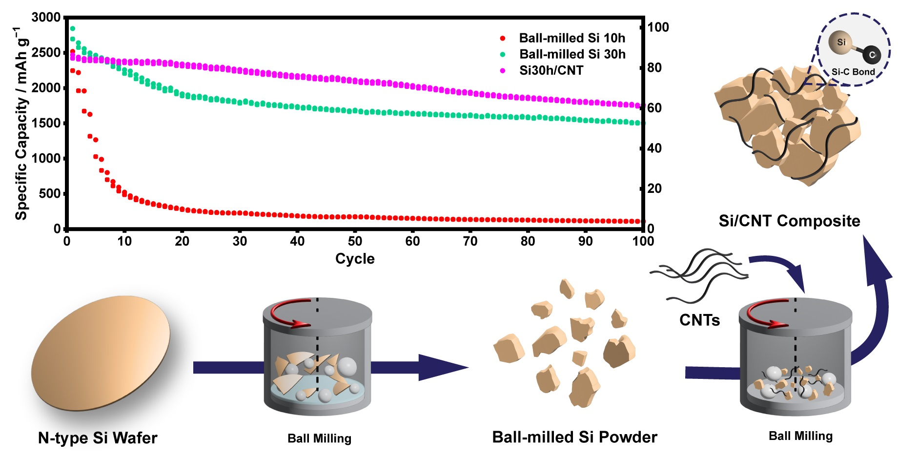
Covalently Bonded Ball-Milled Silicon/CNT Nanocomposite as Lithium-Ion Battery Anode Material

by
Pierre Yosia Edward Koraag
1,2,
Arief Muhammad Firdaus
1,
Naufal Hanif Hawari
1,
Andam Deatama Refino
3,4,
Wibke Dempwolf
5,
Ferry Iskandar
6,7,
Erwin Peiner
3,
Hutomo Suryo Wasisto
3,8 and
Afriyanti Sumboja
1,7,*
1
Material Science and Engineering Research Group, Faculty of Mechanical and Aerospace, Institut Teknologi Bandung, Jl. Ganesha 10, Bandung 40132, Indonesia
2
Department of Materials Science and Engineering, Korea Advanced Institute of Science and Technology (KAIST), Daejeon 34141, Korea
3
Institute of Semiconductor Technology (IHT) and Laboratory for Emerging Nanometrology (LENA), Technische Universität Braunschweig, Hans-Sommer-Straße 66, Braunschweig 38106, Germany
4
Engineering Physics Program, Institut Teknologi Sumatera (ITERA), Jl. Terusan Ryacudu, Way Huwi, Lampung Selatan 35365, Indonesia
5
Institut für Technische Chemie (ITC) and Laboratory for Emerging Nanometrology (LENA), Technische Universität Braunschweig, Hagenring 30, 38106 Braunschweig, Germany
6
Department of Physics, Faculty of Mathematics and Natural Sciences, Institut Teknologi Bandung, Jl. Ganesha 10, Bandung 40132, Indonesia
7
Collaboration Research Center for Advanced Energy Materials, National Research and Innovation Agency—Institut Teknologi Bandung, Jl. Ganesha 10, Bandung 40132, Indonesia
8
PT Nanosense Instrument Indonesia, Umbulharjo, Yogyakarta 55167, Indonesia
*
Author to whom correspondence should be addressed.
Batteries 2022, 8(10), 165; https://doi.org/10.3390/batteries8100165
Submission received: 7 September 2022 / Revised: 27 September 2022 / Accepted: 4 October 2022 / Published: 7 October 2022

Abstract

:
The demand for high-capacity lithium-ion batteries (LIBs) is ever-increasing. Thus, research has been focused on developing silicon-based anodes due to their high theoretical capacity and natural abundance. However, silicon-based anodes still suffer from several drawbacks (e.g., a huge volume expansion during lithiation/delithiation and the low conductivity nature of silicon). In this study, we develop a facile and low-cost synthesis route to create a composite of silicon particles and carbon nanotubes (CNTs) via simple two-step mechanical ball milling with a silicon wafer as the silicon precursor. This method produces a strong interaction between silicon particles and the CNTs, forming Si–C bonds with minimum oxidation of silicon and pulverization of the CNTs. The resulting Si/CNT anode exhibits a first cycle Coulombic efficiency of 98.06%. It retains 71.28% of its first cycle capacity of 2470 mAh g−1 after 100 cycles of charge–discharge at a current density of 400 mA g−1. Furthermore, the Si/CNT anode also shows a good rate capability by retaining 80.15%, and 94.56% of its first cycle capacity at a current density of 1000 mA g−1 and when the current density is reduced back to 200 mA g−1, respectively.

Graphical Abstract

1. Introduction

The global need for sustainable energy storage systems has risen considerably due to the rapid development of portable gadgets and electric cars. Among energy storage devices, lithium-ion batteries (LIBs) are considered to play a key role in supporting various emerging applications as power sources due to their high energy density and long lifetime. With such expanding applications, high-capacity anode materials are urgently needed to improve lithium-ion batteries with a higher gravimetric capacity, a longer cycle life, and a lower fabrication cost [1]. Compared to the current state-of-the-art anode for lithium-ion batteries (i.e., graphite, 372 mAh g−1), silicon (Si) has a larger theoretical gravimetric capacity of up to 3592 mAh g−1 [2,3]. It also has a vast potential in large-scale applications owing to its abundance on the earth’s crust [4].
However, the Si anode sustains several problems during lithiation and delithiation that lead to the degradation of capacity, shelf life, and overall battery performance. These degradations are caused by two major problems. First, the intrinsic conductivity and lithium diffusion rate of the Si anode are low, resulting in a low-rate capability and rapid capacity fading [5,6]. Second, up to a 400% volume expansion of silicon during charging induces cracking, which leads to an unstable solid electrolyte interphase (SEI) layer, thus lowering the Coulombic efficiency, increasing electrode internal resistance, and shortening the cycle life of the batteries [7,8].
Many approaches have been made to increase the performance of the Si anode, such as: (1) Reducing the particle size of silicon to the nanoscale, thus reducing crack formation during its volume expansion. We have previously reported Si nanowire array anodes that exhibit a stable cycling performance at a high current density [9,10]. (2) Forming a composite by combining silicon particles with other materials, such as carbonaceous material, to improve the conductivity and stability of the Si anode [11,12]. (3) Using appropriate binders and additives to create a flexible network that can accommodate the strain during volume expansion and stabilize the formation of the SEI layer [13,14].
Silicon nanostructures with various synthesis methods have been reported. Bottom-up methods (e.g., chemical vapor deposition (CVD), physical vapor deposition (PVD), and sol-gel methods) may not be economically viable in the future due to the complex and high-cost synthesis route [15,16,17]. In addition, silicon precursors (e.g., silane (SiH4) and tetraethyl orthosilicate (TEOS)), are expensive and can be dangerous when directly used in the battery fabrication process [18,19]. Alternatively, top-down approaches, such as mechanical ball milling, are more economically friendly, scalable, and can be carried out at room temperature [20]. It involves mechano-chemical action to reduce the particle size and/or to mix the metastable precursors [21]. With mechanical ball milling, silicon wafers, which are commonly employed in semiconductor device manufacturing, can be utilized as the source of the silicon anode. It can also make use of silicon wafer scraps from the solar cell and semiconductor industries as the low-cost precursor for Si anodes [22].
Furthermore, research focusing on silicon/carbon composite anodes shows that the intrinsic Si–C bond is crucial to keep the integrity and stability of the anode during cycling [23]. However, the strong Si–C bond is not easily formed with mechanical ball milling [24,25]. Commercial ball-milled Si powder/carbon nanotube (CNT) and photovoltaic-derived Si/CNT composites have been employed as the anodes for lithium-ion batteries [25]. However, the resulting Si/CNT composites were not showing the formation of an intrinsic Si–C covalent bond, which can be due to the low rotational milling speed (i.e., 500 rpm) that translates to low energy during milling. Thus, the Si–C bond cannot be formed. Recently, the Si–C bond within the composite was obtained via the magnesiothermic reduction of glass-waste-derived Si/CNT composite [23]. The heat produced during the reaction may drive the formation of the Si–C bond within the composite.
In this work, we prepare the Si/CNT composite using high-energy ball milling (HEBM) using silicon wafers and carbon nanotubes as the precursors. We successfully introduced a strong Si–C covalent bond, thanks to the repeated high collision between the milling balls and the silicon particles during the mechanochemical process. Moreover, after the milling process, minimum changes in the physical properties of CNT are obtained, which can provide better electrochemical performances of the Si/CNT anode. This composite anode has promising electrochemical performance with a simple preparation process and sustainable raw materials.

2. Results and Discussion

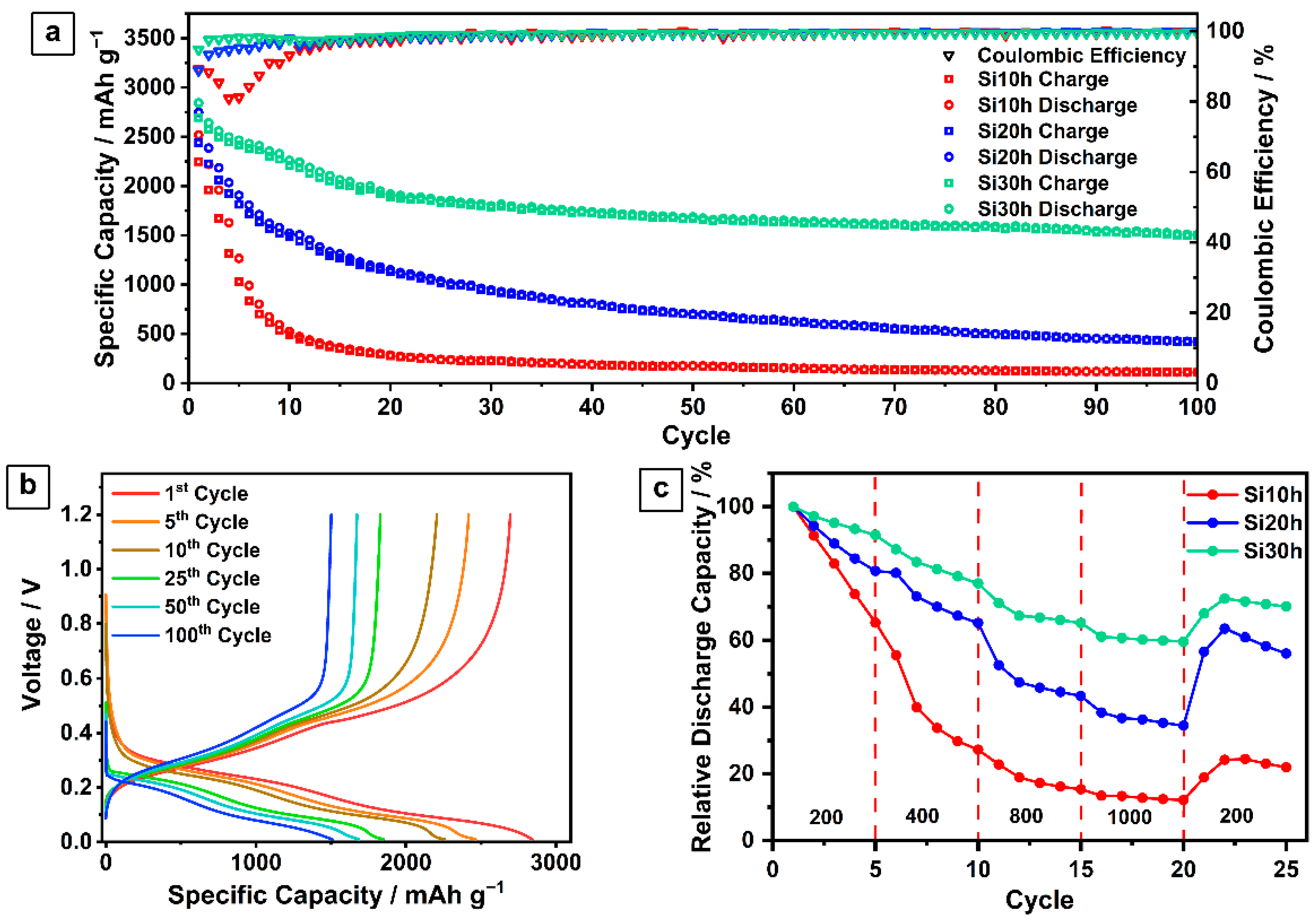
2.1. Ball-Milled Silicon Anode

To obtain ball-milled silicon anodes, silicon wafers were first manually ground using agate mortar to form coarse silicon chunks of submillimeter size (Figure S1). The coarse silicon particles were then ball-milled for 10, 20, and 30 h using ethanol as the solvent to minimize the oxidation and agglomeration of the silicon particles. The samples are labeled as Si10h, Si20h, and Si30h, respectively. Fracturing and cold-welding of the silicon particles occur during the ball-milling due to the high-energy collision. The repeated fracturing of silicon particles is responsible for particle size reduction. Meanwhile, cold welding due to rapid deformation during ball milling forms mechanical interlocking among the particles’ surfaces and may lead to agglomeration of the particles.
The morphologies of the resulting silicon particles are depicted in Figure 1a–c. Morphological evolution is observed with the increase in milling time. Most of the silicon particles are reduced to micrometer size after 10 h of ball milling (Figure 1a), forming irregular plate-like shapes with sharp edges. The particle size is reduced further after 20 h of ball milling, but most are still on the micrometer scale. After 30 h of ball milling, all particles have an average size of several hundred nanometers. Increasing the ball-milling time from 10 h to 20 and 30 h shows that the particle becomes less sharp and more rounded due to repeated fracturing and wearing of sharper particles (Figure 1b,c). When subjected to expansion during lithiation, the more rounded silicon particles tend to undergo isotropic mechanical stress instead of anisotropic stress. Furthermore, the SEI growth on regular shapes also tends to be more stable than on irregular shapes. Therefore, rounded silicon particles are expected to improve the cycling stability of the silicon anode [26].
The particle size distribution of each sample was measured using a particle size analyzer (Figure 1d). The Si10h particles have two size population peaks: 16.0% of the population at 513.7 nm and 84.0% at 6666.7 nm, with an average size of ~5520.3 nm. Meanwhile, Si20h shows a smaller particle size with two population peaks: 11.5% of the population at 402.4 nm and 88.5% at 3205.4 nm, with an average size of ~2859.3 nm. This trend is also followed by Si30h, showing two population peaks: 12.0% of population at 50.5 nm and 88.0% at 740.9 nm, with an average size of ~632.8 nm.
Although a longer milling time produces smaller particle sizes, minimum homogenization in the particle size is observed with the increase in milling time. Since the reduction of particles is caused by fragmentation during the ball milling, a smaller peak size with a lower intensity appears as a fragmented part of the main particle size. The bimodal particle distribution resulting from the ball milling process has also been reported by Nachev et al. [27]. The maximum milling time is stopped at 30 h due to the similar capacity obtained at a higher milling time (Figure S4). Despite that, particle size reduction to the nanometer range has been achieved in Si30h, which will benefit the Si anode performance [28]. It can prevent cracking during the expansion and pulverization of the particles, which can increase the cycling stability of the Si anode. Furthermore, the particle size reduction also enhances the Si anode rate capability due to the shorter distance of lithium diffusion [26,29]. The peaks from the XRD patterns of the pre-ground and ball-milled silicon Si10h, Si20h, and Si30h are consistent with the reference (Figure S2). The peaks at 28.5°, 47.3°, 56.2°, 69.2°, 76.5°, and 88.0° can be assigned to the (111), (220), (311), (400), (331), and (422) planes of the cubic phase of Si (JCPDS No. 27–1402) [30].
To investigate the size effect of the ball-milled silicon on the performance of Li-ion batteries, Si10h, Si20h, and Si30h were employed as the electrode in a Li-ion half-cell configuration. The cycling stability curves of the cells with the Si10h, Si20h, and Si30h electrodes at a current density of 400 mA g−1 during 100 charge–discharge cycles are given in Figure 2a. The charge–discharge profile of the cell with the Si30h electrode is shown in Figure 2b. The first cycle discharge capacities of the cell with the Si10h, Si20h, and Si30h electrodes are 2518, 2747, 2844 mAh g−1, with the first Coulombic efficiency of 89.26%, 88.85%, and 94.78%, respectively. Their Coulombic efficiencies in the next cycles increase and stabilize at ~99% at the 43rd, 37th, and 27th cycle, respectively. At the 100th cycle, the long-term stability of the cells with the Si10h, Si20h, and Si30h electrodes shows capacity retention of 4.35%, 15.33%, and 52.96%, respectively.
Based on the mentioned results, the performance of the cell with the Si30h electrode has significant improvements compared to those with the Si10h and Si20h electrodes. By reducing the size of silicon particles, lithium ions are more able to diffuse into and out of the particles, shortening the diffusion path and improving the capacity and Coulombic efficiency [26]. Small particle sizes are also more immune to crack formation and pulverization, causing significant improvement in capacity retention during cycling [26]. Less pulverization also minimizes the new SEI formation and reduces rupturization of the formed SEI. Hence, it produces a stable SEI, reducing lithium consumption and stabilizing the Coulombic efficiency during cycling. It also prevents SEI build-up that can increase the cell impedance and degrade the capacity during cycling.
The rate capability test of each sample was carried out at various current densities, from 200 mA g−1 to 1000 mA g−1, and back to 200 mA g−1. The cell with the Si30h electrode exhibits superior performance compared to those with the Si20h and Si10h electrode (Figure 2c). It maintains 59.63% of its capacity at 1000 mA g−1 and retains 67.96% of its capacity when the current density is reduced back to 200 mA g−1. This result was significantly improved compared to Si10h with capacity retention of 12.14%, and 18.93% measured at the same current densities (i.e., 1000 and 200 mA g−1). The small particle size of Si30h has a shorter lithium diffusion pathway, resulting in the improved capacity retention at high current rates.

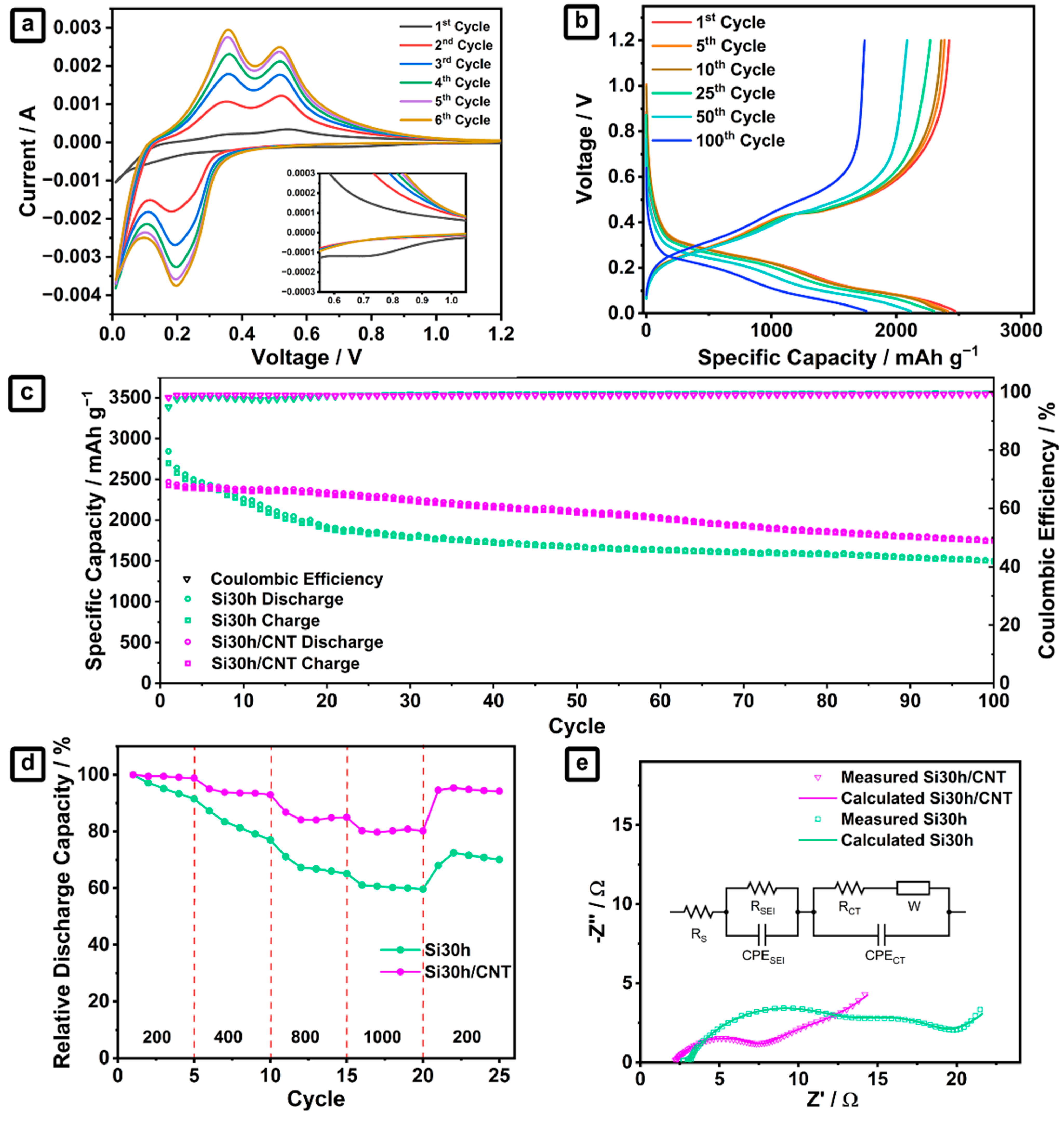
2.2. Ball-Milled Silicon/CNTs Nanocomposites Anode

To further improve the performance of the Si anode, CNT is then introduced to the ball-milled silicon with the optimum electrochemical performance (i.e., Si30h). The as-produced Si30h powder was simply mixed with commercial CNT powder using dry ball-milling for 2 h to obtain Si30h/CNT composite powder. The morphological features of bare Si30h and Si/CNT composite are given in Figure 3a–d. By compositing Si30h with CNT, it can be seen that silicon particles are now interconnected with a web-like CNT matrix (Figure 3c,d). These interconnected structures within the CNT matrix can improve the electrochemical performance of the silicon anode in several ways [31,32]. The CNT matrix with high mechanical properties will hold and prevent silicon particles from pulverizing and detaching during the cycling process. The carbon in CNT may also form a more stable SEI layer due to the higher stability of lithium carbonate (Li2CO3)-rich SEI compared to lithium fluoride (LiF)-rich and lithium oxide (Li2O)-rich SEIs that are obtained in silicon-only electrodes [33].
The XRD patterns of Si30h/CNT and Si30h are given in Figure 3e. The silicon peaks in the Si30h/CNT pattern are consistent with the XRD pattern of Si30h. However, the single-walled CNT (SWCNT) peaks are hardly detected, which can be associated with the absence of the intratube structure of SWCNT, resulting in a broad peak with a low intensity [34]. Hence, the presence of CNT in the composite was investigated via Raman spectroscopy. The Raman spectra of Si30h and Si30h/CNT are shown in Figure 3f. The two peaks at ~516 and ~950 cm−1 are attributed to elemental Si, indicating that Si–Si bonds are formed in both [35]. The Si/CNT owns the vibrational C–C bonds that can be observed at ~1323 and ~1587 cm−1, which belong to the D and G bands of CNT, respectively [36]. The former is known as the disordered degree of CNT, and the latter stands for the graphitization degree of CNT [37]. The G band is split into G+ and G- peaks, which is unique due to the CNT geometry. Regardless of the diameter of CNT, the G+ peak appears around 1590 cm−1. On the other hand, the position of the G- peak, which corresponds to the transverse wave mode, is in inverse proportion to the square diameter of CNT [38].
The Raman spectrum of CNT used in this study was also measured for comparison. A higher ID/IG ratio of Si/CNT at 0.227 compared to the ID/IG of pristine CNT at 0.05 indicates that the CNT in the Si/CNT composite is more disordered than the pristine one. Compared to the recently published articles on Si/CNT composites [23,25,39], our sample has a much lower ID/IG ratio, which translates to a higher graphitization degree of Si/CNT even after 2 h of ball milling. In this case, the higher graphitization degree of CNT provides better electronic conductivity, resulting in improved electrochemical performance [40].
XPS was then employed to investigate the surface chemical composition of the samples and the chemical bond that may be created between Si and CNT during ball-milling. The high-resolution Si 2p spectrum of Si30h is shown in Figure 4a. In addition to the Si–Si bond, the presence of a Si–O bond indicates the oxide formation on the surface due to the atmospheric condition during ball milling [41]. The Si 2p signal of Si30h/CNT (Figure 4b) can be deconvoluted into six peaks, where two peaks at 97.9 and 98.9 eV arise from Si 2p3/2 and Si 2p1/2, respectively [42]. The peaks at 101.9 and 102.8 eV represent two phases of silicon oxide that are formed due to the atmospheric contamination during ball-milling [23]. Compared to Si30h, the increase in oxide formation can be seen in Si30h/CNT due to the additional dry milling time to form the composite. A small peak at 97.9 eV can be attributed to Fe contamination [43], which may come from a stainless-steel jar during the dry milling process.
More importantly, there is a unique peak at 100.8 eV in the Si 2p spectra of Si30h/CNT that does not exist in the Si 2p spectra of Si30h, which indicates the formation of Si–C [23]. Consistent with the Si 2p peak, the C 1s spectra of Si30h/CNT (Figure 4c) also exhibit a peak of the Si–C bond at 283 eV. The strong Si–C bond between Si and CNT helps to maintain the structural integrity of Si30h/CNT during the cycling test. Thus, the cell can deliver a large capacity, good cycling stability, and a high rate capability [23]. The remaining peaks at 284.9, 286.5, and 288.2 eV are attributed to SiCO, C=O, and COOH, respectively, which can be associated with the presence of oxygen during ball milling [42].
Figure 5a shows the cyclic voltammograms (CVs) of the cell with the Si30h/CNT electrode for the first six cycles at a scanning rate of 0.1 mV s−1 within a voltage range of 0.01–1.2 V. The broad cathodic peak at ~0.19 V is ascribed to the formation of LixSi, while the anodic peaks at ~0.35 and ~0.52 V are the characteristics of the Li delithiation from LixSi to amorphous Si [23]. A small peak around 0.6–1.0 V is observed during the first CV cycle of Si30h/CNT with Si30h, which cannot be seen in the following cycles (Figure 5a and Figure S5). This peak is attributed to the irreversible capacity loss, originating from the SEI formation at the first lithiation of the silicon anode [44]. There is no significant difference between the CV peaks and CV profiles of Si30h/CNT (Figure 5a) with Si30h (Figure S5). Furthermore, the silicon oxides formed during ball milling of either Si30h or Si30h/CNT may not take part during the lithiation process, as the reduction peak of silicon oxide (~1.65 V) is not visible in the first cycle [45,46]. Therefore, it can be concluded that the addition of CNT and the presence of silicon oxides at the surface do not produce any significant changes in the lithiation/delithiation reaction of the Si anode in this study.
The voltage profile of Si30h/CNT during the charge–discharge test for 100 cycles is displayed in Figure 5b. Using the same test parameter during cell characterization, the cell with the Si30h/CNT electrode exhibits an even higher cycling performance than that with the Si30h electrode (Figure 5c). The first cycle discharge capacity of the cell with the Si30h/CNT electrode is at 2470 mAh g−1, with a first Coulombic efficiency of 98.06%. The discharge capacity of Si30h/CNT is in the higher range of the reported ball-milled Si/CNT anode in the literature (Table S1). At the 100th cycle, it can still retain 71.28% of its first cycle capacity, showing a significant improvement over the cell with the Si30h electrode (i.e., 52.96%). A strong Si–C bond between CNT and Si forms an interconnected matrix that can compensate for the expansion of Si particles. Furthermore, the good mechanical property of CNT holds the particles together, preventing pulverization and SEI layer rupture, resulting in the improved cycling stability of the composite electrode [24,47]. CNT also serves as a conductive agent that enhances electrical conductivity and the Li-ion transfer path, decreasing impedance and improving the rate capability. A significant improvement can be observed in the rate capability of the cell with the Si30h/CNT electrode (Figure 5d). It maintains 80.15% of its first cycle capacity at 1000 mA g−1, and retains 94.56% of its initial capacity when the current density is reduced back to 200 mA g−1 (the cell with the Si30h electrode only retains 59.60% and 67.96% of its capacity at the same current density). Furthermore, Figure 5e compares the Nyquist plot between the cell with the Si30h and Si30h/CNT electrodes extracted from the electrochemical impedance spectroscopy (EIS) measurement. The Nyquist plot consists of two depressed semicircles at high and middle frequencies, as well as a tail in the low-frequency region. The equivalent circuit consists of RS representing internal series resistance, RSEI describing the resistance of SEI formed during prelithiation, RCT denoting the charge transfer resistance, W representing the Li diffusion in solid Si, and the constant phase element (CPE) showing the capacitive nature of the double-layer.
A solid line represents the measured Nyquist plot based on fitting. Based on the resulting fitting parameter (Table S2), the cell with the Si30/CNT electrode shows a lower RCT than those with the Si30h electrode, indicating fast kinetics of charge displacement at the electrode–electrolyte interface due to the fast transport channel provided by CNT. The cell with the Si30/CNT electrode also shows a significantly lower RSEI, indicating a smaller amount of SEI build-up during prelithiation, which can be attributed to the stable SEI formation and the ability of the CNT matrix to hold the particles together that prevents the repeated rupturization and excessive formation of SEI. Furthermore, the cell with the Si30h/CNT electrode also offers lower RS, resulting from the higher electrical conductivity of Si30h/CNT. The EIS measurement supports the results of cycling performance and rate capability. It further confirms the ability of the CNT matrix to increase lithium-ion diffusion and electric conductivity, as well as to stabilize SEI formation [48].

3. Materials and Methods

3.1. Synthesis of Si/CNT Composite

Silicon wafer (n-type, Siegert Wafer GmbH, Aachen, Germany) was ground using agate mortar into smaller pieces, resulting in pre-ground silicon. 0.85 g of pre-ground silicon, zirconia balls, and ethanol was added into a 50 mL stainless steel milling jar, which was then inserted into a planetary ball milling machine (MTI MSK-SFM-1, Richmond, CA, USA). The wet milling process was carried out to prevent the oxidation and agglomeration of silicon powders during the ball milling. The ball milling was performed with a milling speed of 1200 rpm for 10, 20, and 30 h to reduce the particle size of silicon. The mass of the milling ball to powder ratio (BPR) was set to be 20:1 with eight zirconia balls (one of 15.25 mm, two of 8.48 mm, and five of 4.99 mm in diameter). The resulting silicon powders were collected and dried in a vacuum oven at 100 °C for 12 h to remove the ethanol from the silicon powders.
To synthesize Si/CNT nanocomposite, the second step of the ball milling process was carried out. The resulting silicon powders with 30 h of milling time were mixed with CNT (single-walled, 99%, Sigma Aldrich, Singapore) to form Si/CNT composite. Amounts of 0.057 g silicon powder and 0.01 g CNT were put into a 50 mL stainless steel milling jar and ball-milled with a milling speed of 1200 rpm for 2 h. The process was carried out in dry milling condition to promote the interaction between silicon powder and CNT. The BPR was 117:1 with four zirconia balls having a diameter of 8.48 mm.

3.2. Material Characterizations

The particle size distribution of silicon powder was analyzed using a dynamic light scattering particle size analyzer (Horiba SZ-100, Kyoto, Japan). The silicon powders were dispersed in 10 mM KCl solution and sonicated for 15 min prior to the measurement. The crystal structures of silicon powder and Si/CNT composite were characterized using an X-ray diffractometer (XRD, Bruker D8 Advance, Billerica, MA, USA) with Cu-Kα radiation (λ = 1.518 Å). Raman spectroscopy was conducted using Renishaw inVia™ Qontor Raman microscope with a laser wavelength of 532 nm and a 50× objective lens with a numerical aperture of 0.5. The morphology and microstructure of silicon powder and composite were observed using a scanning electron microscope (Hitachi SEM SU3500, Kyoto, Japan) and a transmission electron microscope (Hitachi TEM HT7700, Kyoto, Japan). X-ray photoelectron spectroscopy (XPS) has been performed on a Kratos Axis Supra spectrometer (Kratos Analytical Ltd., Manchester, UK) using monochromatic Al-Ka radiation at 1486.6 eV. The C 1s, O 1s, and Si 2p high-resolution spectra were obtained using a step size of 0.1 eV and a pass energy of 20 eV. Binding energy values were calibrated to the C–C bound (285 eV). The pressure in the chamber during analysis was in the range of 2 × 10⁻⁹ Torr. The analysis of data has been performed by using the CasaXPS software version 2.3.25.

3.3. Electrochemical Measurements

The silicon electrodes were prepared by mixing 20 wt% of carboxymethyl cellulose (CMC, Mw = 90.000, Sigma Aldrich, Singapore), 29 wt% super P (Timcal, Bodio, Switzerland), and 51 wt% ball-milled silicon powder. A total of 20 wt% super P was used in Si/CNT composite electrode. A high binder and additive ratio were employed to enhance the cycling performance of the Si-based anode. First, the CMC was dissolved in DI water to form a binder solution. Then, the Si or Si/CNT powder and super P were mixed with CMC solution using agate mortar to create a slurry. The slurry was then tape-casted onto copper foil as a current collector and vacuum-dried at room temperature for 12 h. Afterward, the casted electrode was rested in a humid atmosphere (83% RH) for three days to enhance the interaction between the silicon particles, binder, and current collector. The casted electrode was vacuum dried at 100 °C for 12 h to completely remove the water content and cut into circle-shaped electrodes with a diameter of 1.5 cm. The resulting electrodes with mass loading of 1.70 ± 0.20 mg cm−2 were assembled into CR2302 coin cells. A half-cell configuration was fabricated using as-obtained electrodes, lithium metal counter electrodes, and Celgard (CG 3401) separator. Used as an electrolyte was 1 M LiPF6 solution in ethylene carbonate (EC)-dimethyl carbonate (DMC)-diethyl carbonate (DEC) (1:1:1 vol), with the addition of 10 vol% fluoroethylene carbonate (FEC) as an additive to promote the formation of stable SEI [49]. The assembly was done inside the glove box (Kiyon, Seoul, South Korea) with an argon atmosphere.
Galvanostatic charge–discharge measurement was carried out between 0.01 to 1.2 V on a battery tester (Neware, Hong Kong, China). The prelithiation step was performed before cycling and the rate capability test at a current density of 100 mA g−1 for three cycles. The cycling test was conducted at a current density of 400 mA g−1. The rate capability tests were conducted at 200, 400, 800, 1000, and 200 mA g−1 for five cycles at each current density. The cyclic voltammetry was performed at a scanning rate of 0.1 mV s−1 within a voltage range of 0.01–1.2 V on a potentiostat/galvanostat electrochemical workstation (CS150 Corrtest, Wuhan, China) without any prelithiation step. Electrochemical impedance spectroscopy (EIS) was conducted after the prelithiation step using frequency response analysis ranging from 0.1 Hz to 1 MHz with 10 mV potential amplitude on a potentiostat (PARSTAT 3000A, Berwyn, PA, USA).

4. Conclusions

To summarize, a simple and low-cost ball milling method has been developed to synthesize Si/CNT nanocomposites. Two-step ball milling has been utilized, where the first step is to reduce the Si particle size, while the second step is to create a composite between the Si particle and the CNT with a strong Si–C bond. This high-energy ball milling has been shown to create nanosized silicon particles. It allows the formation of strong interaction between the CNT matrix and silicon particles with minimum oxidation, leading to the improved electrochemical performances of the battery. The cell with Si30h/CNT electrode exhibits an excellent first cycle Coulombic efficiency of 98.06% and is able to retain 71.28% of its first cycle capacity of 2470 mAh g−1 after 100 cycles. It also shows a good rate capability by retaining 80.15% and 94.56% of its first cycle capacity at 1000 mA g−1 and when the current density is reduced back to 200 mA g−1, respectively. The interconnected structure between the CNT web-like matrix and silicon particles with the formation of the Si–C bond improves the conductivity and stability of the silicon anodes. This facile method paves the way for the large-scale production of silicon/carbon composite anodes for lithium-ion batteries.

Supplementary Materials

The following supporting information can be downloaded at: www.mdpi.com/2313-0105/8/10/165/s1, Figure S1: SEM image of pre-ground silicon; Figure S2: XRD spectra of Si10h, Si20h, and Si30h; Figure S3: SEM results of (a) Si30h and (b) Si40h; Figure S4: Cycling performance of the cell with Si30h and Si40h at a current density of 400 mA g−1; Figure S5: Cyclic voltammograms of Si30h; Figure S6: Cycling performance of the cell with Si20h/CNT and Si30h/CNT electrode at a current density of 200 mA g–1; Table S1: Performance of ball-milled silicon and silicon/CNT anodes in literature; Table S2: Resistance values of the sample based on fitting on the equivalent circuit model.(“References [23,24,25,29,39,50,51,52,53,54,55] are cited in the Supplementary Materials”).

Author Contributions

Conceptualization, P.Y.E.K., A.M.F. and A.S.; Methodology, P.Y.E.K., A.M.F., N.H.H., A.D.R., W.D. and A.S.; Validation, F.I., E.P., H.S.W. and A.S.; Formal analysis and investigation, P.Y.E.K., A.M.F., N.H.H., W.D. and A.S.; Resources, F.I., E.P., H.S.W. and A.S.; Data curation, P.Y.E.K., A.M.F., N.H.H. and A.D.R.; Writing—Original Draft Preparation, P.Y.E.K., A.M.F., N.H.H. and A.S.; Writing—Review and Editing, A.D.R., F.I., E.P., H.S.W. and A.S.; Supervision, E.P., H.S.W. and A.S.; Funding Acquisition, H.S.W., and A.S. All authors have read and agreed to the published version of the manuscript.

Funding

This research was funded by Indonesian Endowment Fund for Education (LPDP) under the Southeast Asia-Europe Joint Funding Scheme for Research and Innovation and the German Federal Ministry of Education and Research (BMBF) for the project “3D nano-engineered silicon anodes for high-energy-density lithium-ion rechargeable batteries (SiNanoBatt)” under no. 01DP21003.

Institutional Review Board Statement

Not applicable.

Informed Consent Statement

Not applicable.

Data Availability Statement

The data that support the findings of this study are available from the corresponding author upon reasonable request.

Acknowledgments

The authors thank Alina Syring and Tobias Voss for their support in Raman spectroscopy characterization. XPS measurements have been performed on an instrument supported by the German Research Foundation (DFG) (INST 188/444-1 FUGB).

Conflicts of Interest

Authors declare no conflict of interest.

References

  1. Houache, M.S.E.; Yim, C.-H.; Karkar, Z.; Abu-Lebdeh, Y. On the Current and Future Outlook of Battery Chemistries for Electric Vehicles—Mini Review. Batteries 2022, 8, 70. [Google Scholar] [CrossRef]
  2. Zhang, J.; Zhang, C.; Liu, Z.; Zheng, J.; Zuo, Y.; Xue, C.; Li, C.; Cheng, B. High-performance ball-milled SiOx anodes for lithium ion batteries. J. Power Sources 2017, 339, 86–92. [Google Scholar] [CrossRef]
  3. Ping, W.; Yang, C.; Bao, Y.; Wang, C.; Xie, H.; Hitz, E.; Cheng, J.; Li, T.; Hu, L. A silicon anode for garnet-based all-solid-state batteries: Interfaces and nanomechanics. Energy Storage Mater. 2019, 21, 246–252. [Google Scholar] [CrossRef]
  4. Du, F.-H.; Wang, K.-X.; Chen, J.-S. Strategies to succeed in improving the lithium-ion storage properties of silicon nanomaterials. J. Mater. Chem. A 2016, 4, 32–50. [Google Scholar] [CrossRef]
  5. Kwon, H.-T.; Lee, C.K.; Jeon, K.-J.; Park, C.-M. Silicon diphosphide: A Si-based three-dimensional crystalline framework as a high-performance Li-ion battery anode. ACS Nano 2016, 10, 5701–5709. [Google Scholar] [CrossRef] [PubMed]
  6. Jiang, Z.; Li, C.; Hao, S.; Zhu, K.; Zhang, P. An easy way for preparing high performance porous silicon powder by acid etching Al–Si alloy powder for lithium ion battery. Electrochim. Acta 2014, 115, 393–398. [Google Scholar] [CrossRef]
  7. Jo, H.; Kim, J.; Nguyen, D.-T.; Kang, K.K.; Jeon, D.-M.; Yang, A.-R.; Song, S.-W. Stabilizing the solid electrolyte interphase layer and cycling performance of silicon–graphite battery anode by using a binary additive of fluorinated carbonates. J. Phys. Chem. C 2016, 120, 22466–22475. [Google Scholar] [CrossRef]
  8. Zhang, J.; Zhang, C.; Wu, S.; Zhang, X.; Li, C.; Xue, C.; Cheng, B. High-columbic-efficiency lithium battery based on silicon particle materials. Nanoscale Res. Lett. 2015, 10, 395. [Google Scholar] [CrossRef] [PubMed] [Green Version]
  9. Nugroho, A.P.; Hawari, N.H.; Prakoso, B.; Refino, A.D.; Yulianto, N.; Iskandar, F.; Kartini, E.; Peiner, E.; Wasisto, H.S.; Sumboja, A. Vertically Aligned n-Type Silicon Nanowire Array as a Free-Standing Anode for Lithium-Ion Batteries. Nanomaterials 2021, 11, 3137. [Google Scholar] [CrossRef] [PubMed]
  10. Refino, A.D.; Yulianto, N.; Syamsu, I.; Nugroho, A.P.; Hawari, N.H.; Syring, A.; Kartini, E.; Iskandar, F.; Voss, T.; Sumboja, A.; et al. Versatilely tuned vertical silicon nanowire arrays by cryogenic reactive ion etching as a lithium-ion battery anode. Sci. Rep. 2021, 11, 19779. [Google Scholar] [CrossRef] [PubMed]
  11. Nzabahimana, J.; Liu, Z.; Guo, S.; Wang, L.; Hu, X. Top-Down Synthesis of Silicon/Carbon Composite Anode Materials for Lithium-Ion Batteries: Mechanical Milling and Etching. Chem. Sus. Chem. 2020, 13, 1923–1946. [Google Scholar] [CrossRef] [PubMed]
  12. Zhao, S.; Xu, Y.; Xian, X.; Liu, N.; Li, W. Fabrication of Porous Si@C Composites with Core-Shell Structure and Their Electrochemical Performance for Li-ion Batteries. Batteries 2019, 5, 27. [Google Scholar] [CrossRef] [Green Version]
  13. Wei, L.; Chen, C.; Hou, Z.; Wei, H. Poly (acrylic acid sodium) grafted carboxymethyl cellulose as a high performance polymer binder for silicon anode in lithium ion batteries. Sci. Rep. 2016, 6, 19583. [Google Scholar] [CrossRef] [Green Version]
  14. Porcher, W.; Chazelle, S.; Boulineau, A.; Mariage, N.; Alper, J.; Van Rompaey, T.; Bridel, J.-S.; Haon, C. Understanding polyacrylic acid and lithium polyacrylate binder behavior in silicon based electrodes for Li-ion batteries. J. Electrochem. Soc. 2017, 164, A3633. [Google Scholar] [CrossRef]
  15. Wang, Q.; Ban, Y.; Zhou, H.; Zhang, L.; Huang, Y.; Shao, W.; Chen, S. Preparation of Si/TiO2 Composite by the Sol-Gel Method Using As the Lithium-Ion Battery Anode. IOP Conf. Ser.: Mater. Sci. Eng. 2017, 250, 012054. [Google Scholar] [CrossRef]
  16. Liu, B.; Huang, P.; Xie, Z.; Huang, Q. Large-Scale Production of a Silicon Nanowire/Graphite Composites Anode via the CVD Method for High-Performance Lithium-Ion Batteries. Energy Fuels 2021, 35, 2758–2765. [Google Scholar] [CrossRef]
  17. Wang, Z.; Li, Y.; Huang, S.; Liu, L.; Wang, Y.; Jin, J.; Kong, D.; Zhang, L.; Schmidt, O.G. PVD customized 2D porous amorphous silicon nanoflakes percolated with carbon nanotubes for high areal capacity lithium ion batteries. J. Mater. Chem. A 2020, 8, 4836–4843. [Google Scholar] [CrossRef]
  18. Fasoli, A.; Milne, W. Overview and status of bottom-up silicon nanowire electronics. Mater. Sci. Semicond. Process. 2012, 15, 601–614. [Google Scholar] [CrossRef]
  19. Magasinski, A.; Dixon, P.; Hertzberg, B.; Kvit, A.; Ayala, J.; Yushin, G. High-performance lithium-ion anodes using a hierarchical bottom-up approach. Nat. Mater. 2010, 9, 353–358. [Google Scholar] [CrossRef] [PubMed]
  20. Yuda, A.P.; Koraag, P.Y.E.; Iskandar, F.; Wasisto, H.S.; Sumboja, A. Advances of the top-down synthesis approach for high-performance silicon anodes in Li-ion batteries. J. Mater. Chem. A 2021, 9, 18906–18926. [Google Scholar] [CrossRef]
  21. Tarascon, J.-M.; Morcrette, M.; Saint, J.; Aymard, L.; Janot, R. On the benefits of ball milling within the field of rechargeable Li-based batteries. C. R. Chim. 2005, 8, 17–26. [Google Scholar] [CrossRef]
  22. Yang, T.; Gao, Y.; Tang, Y.; Zhang, Y.; Li, X.; Liu, L. Porous silicon from industrial waste engineered for superior stability lithium-ion battery anodes. J. Nanopart. Res. 2021, 23, 209. [Google Scholar] [CrossRef]
  23. Mei, S.; Liu, Y.; Fu, J.; Guo, S.; Deng, J.; Peng, X.; Zhang, X.; Gao, B.; Huo, K.; Chu, P.K. Waste-glass-derived silicon/CNTs composite with strong Si-C covalent bonding for advanced anode materials in lithium-ion batteries. Appl. Surf. Sci. 2021, 563, 150280. [Google Scholar] [CrossRef]
  24. Eom, J.Y.; Kwon, H.S. Preparation of single-walled carbon nanotube/silicon composites and their lithium storage properties. ACS Appl. Mater. Interfaces 2011, 3, 1015–1021. [Google Scholar] [CrossRef] [PubMed]
  25. Wang, C.; Niu, X.; Wang, D.; Zhang, W.; Shi, H.; Yu, L.; Wang, C.; Xiong, Z.; Ji, Z.; Yan, X.; et al. Simple preparation of Si/CNTs/C composite derived from photovoltaic waste silicon powder as high-performance anode material for Li-ion batteries. Powder Technol. 2022, 408, 117744. [Google Scholar] [CrossRef]
  26. Zhu, G.; Wang, Y.; Yang, S.; Qu, Q.; Zheng, H. Correlation between the physical parameters and the electrochemical performance of a silicon anode in lithium-ion batteries. J. Mater. 2019, 5, 164–175. [Google Scholar] [CrossRef]
  27. Nachev, S.; Rango, P.; Skryabina, N.; Skachkov, A.; Aptukov, V.; Fruchart, D.; Marty, P. international journal of hydrogen energy. Int. J. Hydrog. Energy 2015, 40, 17065–17074. [Google Scholar] [CrossRef]
  28. Mu, G.; Wu, B.; Ma, C.; Wu, F. Dynamics analysis of Si electrode particle size effect employing accurate Si model. Electrochim. Acta 2021, 377, 138110. [Google Scholar] [CrossRef]
  29. Gauthier, M.; Mazouzi, D.; Reyter, D.; Lestriez, B.; Moreau, P.; Guyomard, D.; Roué, L. A low-cost and high performance ball-milled Si-based negative electrode for high-energy Li-ion batteries. Energy Environ. Sci. 2013, 6, 2145–2155. [Google Scholar] [CrossRef]
  30. Hubbard, C.; Swanson, H.; Mauer, F. A Silicon Powder Diffraction Standard Reference Material. J. Appl. Crystallogr. 1975, 8, 45–48. [Google Scholar] [CrossRef]
  31. Fu, J.; Liu, H.; Liao, L.; Fan, P.; Wang, Z.; Wu, Y.; Zhang, Z.; Hai, Y.; Lv, G.; Mei, L.; et al. Ultrathin Si/CNTs Paper-Like Composite for Flexible Li-Ion Battery Anode With High Volumetric Capacity. Front. Chem. 2018, 6, 624. [Google Scholar] [CrossRef]
  32. Chou, S.-L.; Zhao, Y.; Wang, J.-Z.; Chen, Z.-X.; Liu, H.-K.; Dou, S.-X. Silicon/Single-Walled Carbon Nanotube Composite Paper as a Flexible Anode Material for Lithium Ion Batteries. J. Phys. Chem. C 2010, 114, 15862–15867. [Google Scholar] [CrossRef] [Green Version]
  33. Roland, A.; Fullenwarth, J.; Ledeuil, J.-B.; Martinez, H.; Louvain, N.; Monconduit, L. How carbon coating or continuous carbon pitch matrix influence the silicon electrode/electrolyte interfaces and the performance in Li-ion batteries. Battery Energy 2022, 1, 20210009. [Google Scholar] [CrossRef]
  34. Futaba, D.N.; Yamada, T.; Kobashi, K.; Yumura, M.; Hata, K. Macroscopic Wall Number Analysis of Single-Walled, Double-Walled, and Few-Walled Carbon Nanotubes by X-ray Diffraction. J. Am. Chem. Soc. 2011, 133, 5716–5719. [Google Scholar] [CrossRef] [PubMed]
  35. Rotshteyn, V.M.; Turdaliev, T.K.; Ashurov, K.B. Analysis of Porous Nanosilicon by Raman Spectroscopy. J. Appl. Spectrosc. 2022, 89, 43–48. [Google Scholar] [CrossRef]
  36. Yan, X.; Suzuki, T.; Kitahama, Y.; Sato, H.; Itoh, T.; Ozaki, Y. A study on the interaction of single-walled carbon nanotubes (SWCNTs) and polystyrene (PS) at the interface in SWCNT–PS nanocomposites using tip-enhanced Raman spectroscopy. Phys. Chem. Chem. Phys. 2013, 15, 20618–20624. [Google Scholar] [CrossRef]
  37. Huang, T.; Xu, Z.; Zeng, G.; Zhang, P.; Song, T.; Wang, Y.; Wang, T.; Huang, S.; Wang, T.; Zeng, H. Selective deposition of plasmonic copper on few layers graphene with specific defects for efficiently synchronous photocatalytic hydrogen production. Carbon 2019, 143, 257–267. [Google Scholar] [CrossRef]
  38. Telg, H.; Duque, J.G.; Staiger, M.; Tu, X.; Hennrich, F.; Kappes, M.M.; Zheng, M.; Maultzsch, J.; Thomsen, C.; Doorn, S.K. Chiral Index Dependence of the G+ and G– Raman Modes in Semiconducting Carbon Nanotubes. ACS Nano 2012, 6, 904–911. [Google Scholar] [CrossRef] [PubMed]
  39. Shi, J.; Jiang, X.; Ban, B.; Li, J.; Chen, J. Carbon nanotubes-enhanced lithium storage capacity of recovered silicon/carbon anodes produced from solar-grade silicon kerf scrap. Electrochim. Acta 2021, 381, 138269. [Google Scholar] [CrossRef]
  40. Xiao, Z.; Yu, C.; Lin, X.; Chen, X.; Zhang, C.; Wei, F. Uniform coating of nano-carbon layer on SiOx in aggregated fluidized bed as high-performance anode material. Carbon 2019, 149, 462–470. [Google Scholar] [CrossRef]
  41. Cao, Y.; Dunlap, R.A.; Obrovac, M.N. Electrochemistry and Thermal Behavior of SiOx Made by Reactive Gas Milling. J. Electrochem. Soc. 2020, 167, 110501. [Google Scholar] [CrossRef]
  42. Palomino, J.; Varshney, D.; Weiner, B.R.; Morell, G. Study of the Structural Changes Undergone by Hybrid Nanostructured Si-CNTs Employed as an Anode Material in a Rechargeable Lithium-Ion Battery. J. Phys. Chem. C 2015, 119, 21125–21134. [Google Scholar] [CrossRef]
  43. Ohtsu, N.; Oku, M.; Satoh, K.; Wagatsuma, K. Dependence of core-level XPS spectra on iron silicide phase. Appl. Surf. Sci. 2013, 264, 219–224. [Google Scholar] [CrossRef]
  44. Cong, R.; Choi, J.-Y.; Song, J.-B.; Jo, M.; Lee, H.; Lee, C.-S. Characteristics and electrochemical performances of silicon/carbon nanofiber/graphene composite films as anode materials for binder-free lithium-ion batteries. Sci. Rep. 2021, 11, 1283. [Google Scholar] [CrossRef] [PubMed]
  45. Gao, X.; Gao, Y.; Li, Q.; Wang, Y.; Zhao, D.; Xu, G.; Zhong, Z.; Su, F. Scalable synthesis of high-performance anode material SiOx/C for lithium-ion batteries by employing the Rochow reaction process. J. Alloys Compd. 2022, 902, 163668. [Google Scholar] [CrossRef]
  46. Liu, Z.; Zhao, Y.; He, R.; Luo, W.; Meng, J.; Yu, Q.; Zhao, D.; Zhou, L.; Mai, L. Yolk@Shell SiOx/C microspheres with semi-graphitic carbon coating on the exterior and interior surfaces for durable lithium storage. Energy Storage Mater. 2019, 19, 299–305. [Google Scholar] [CrossRef]
  47. Zeferino González, I.; Chiu, H.-C.; Gauvin, R.; Demopoulos, G.P.; Verde-Gómez, Y. Silicon doped carbon nanotubes as high energy anode for lithium-ion batteries. Mater. Today Commun. 2022, 30, 103158. [Google Scholar] [CrossRef]
  48. Ikonen, T.; Kalidas, N.; Lahtinen, K.; Isoniemi, T.; Toppari, J.J.; Vázquez, E.; Herrero-Chamorro, M.A.; Fierro, J.L.G.; Kallio, T.; Lehto, V.-P. Conjugation with carbon nanotubes improves the performance of mesoporous silicon as Li-ion battery anode. Sci. Rep. 2020, 10, 5589. [Google Scholar] [CrossRef] [Green Version]
  49. Parfeneva, A.V.; Rumyantsev, A.M.; Lozhkina, D.A.; Maximov, M.Y.; Astrova, E.V. Influence of Fluoroethylene Carbonate in the Composition of an Aprotic Electrolyte on the Electrochemical Characteristics of LIB’s Anodes Based on Carbonized Nanosilicon. Batteries 2022, 8, 91. [Google Scholar] [CrossRef]
  50. Sohn, M.; Park, H.I.; Kim, H. Foamed silicon particles as a high capacity anode material for lithium-ion batteries. Chem. Commun. 2017, 53, 11897–11900. [Google Scholar] [CrossRef]
  51. Zhou, W.; Chen, J.; Xu, X.; Han, X.; Chen, M.; Yang, L.; Hirano, S.I. Large areal capacity all-in-one lithium-ion battery based on boron-doped silicon/carbon hybrid anode material and cellulose framework. J. Colloid Interface Sci. 2022, 612, 679–688. [Google Scholar] [CrossRef] [PubMed]
  52. Shin, M.S.; Choi, C.K.; Park, M.S.; Lee, S.M. Spherical Silicon/CNT/Carbon Composite Wrapped with Graphene as an Anode Material for Lithium-Ion Batteries. J. Electrochem. Sci. Technol. 2022, 13, 159–166. [Google Scholar] [CrossRef]
  53. Wang, C.; Yang, Y.; Lu, D.; Guan, R.; Wang, J.; Bian, X. Si-based composite deriving from wok ash waste as high-performance anode for Li-ion battery. J. Alloys Compd. 2021, 858, 157680. [Google Scholar] [CrossRef]
  54. Lee, J.H.; Yoon, C.S.; Hwang, J.Y.; Kim, S.J.; Maglia, F.; Lamp, P.; Myung, S.T.; Sun, Y.K. High-energy-density lithium-ion battery using a carbon-nanotube–Si composite anode and a compositionally graded Li[Ni0.85Co0.05Mn0.10]O2 cathode. Energy Environ. Sci. 2016, 9, 2152–2158. [Google Scholar] [CrossRef]
  55. Tugrul, C.; Mehmet, O.G.; Hatem, A. Enhancing electrochemical performance of silicon anodes by dispersing MWCNTs using planetary ball milling. Microelectron. Eng. 2013, 108, 169–176. [Google Scholar]
Figure 1. SEM images of silicon particles resulting from the ball-milling process for (a) 10 h (Si10h), (b) 20 h (Si20h), and (c) 30 h (Si30h). (d) Particle size distribution of Si10h, Si20h, and Si30h.
Batteries 08 00165 g001
Figure 2. (a) Cycling stability curves of the cells with Si10h, Si20h, and Si30h electrodes at 400 mA g−1; (b) Charge/discharge profiles of the cell with Si30h electrode; (c) Rate capability curves of the cells with Si10h, Si20h, and Si30h electrodes.
Batteries 08 00165 g002
Figure 3. (a) SEM and (b) TEM images of Si30h; (c) SEM and (d) TEM images of Si30h/CNT; (e) XRD spectra of Si30h and Si30h/CNT; (f) Raman spectra of Si30h and Si30h/CNT.
Batteries 08 00165 g003
Figure 4. XPS high-resolution spectra: (a) Si 2p spectra of Si30h, (b) Si 2p spectra of Si30h/CNT, and (c) C 1s spectra of Si30h/CNT.
Batteries 08 00165 g004
Figure 5. (a) Cyclic voltammograms (CVs) and (b) charge/discharge profiles of the cell with the Si30h/CNT electrode. (c) Cycling performance, (d) rate performance, and (e) Nyquist plot with the fitted equivalent circuit of the cells with Si30h and Si30h/CNT electrodes.
Batteries 08 00165 g005
Publisher’s Note: MDPI stays neutral with regard to jurisdictional claims in published maps and institutional affiliations.

