Article

A Comprehensive Study of Degradation Characteristics and Mechanisms of Commercial Li(NiMnCo)O2 EV Batteries under Vehicle-To-Grid (V2G) Services

1
State Key Laboratory of Automotive Safety and Energy, Tsinghua University, Beijing 100084, China
2
School of Mechanical Engineering, University of Shanghai for Science and Technology, Shanghai 200093, China
3
Beijing LianYu Technology Co., Ltd., Beijing 100083, China
*
Authors to whom correspondence should be addressed.
Batteries 2022, 8(10), 188; https://doi.org/10.3390/batteries8100188
Submission received: 13 September 2022 / Revised: 4 October 2022 / Accepted: 11 October 2022 / Published: 17 October 2022
(This article belongs to the Special Issue Battery Energy Storage in Advanced Power Systems)

Abstract

:
Lithium-ion batteries on electric vehicles have been increasingly deployed for the enhancement of grid reliability and integration of renewable energy, while users are concerned about extra battery degradation caused by vehicle-to-grid (V2G) operations. This paper details a multi-year cycling study of commercial 24 Ah pouch batteries with Li(NiMnCo)O2 (NCM) cathode, varying the average state of charge (SOC), depth of discharge (DOD), and charging rate by 33 groups of experiment matrix. Based on the reduced freedom voltage parameter reconstruction (RF-VPR), a more efficient non-intrusive diagnosis is combined with incremental capacity (IC) analysis to evaluate the aging mechanisms including loss of lithium-ion inventory and loss of active material on the cathode and anode. By analyzing the evolution of indicator parameters and the cumulative degradation function (CDF) of the battery capacity, a non-linear degradation model with calendar and cyclic aging is established to evaluate the battery aging cost under different unmanaged charging (V0G) and V2G scenarios. The result shows that, although the extra energy throughput would cause cyclic degradation, discharging from SOC 90 to 65% by V2G will surprisingly alleviate the battery decaying by 0.95% compared to the EV charged within 90–100% SOC, due to the improvement of calendar life. By optimal charging strategies, the connection to the smart grid can potentially extend the EV battery life beyond the scenarios without V2G.

1. Introduction

Future power systems would face the problem of an enlarged energy imbalance gap and declined inertia stability due to ‘dual-high’ characteristics, namely, the high penetration of intermittent renewable energy (RE) and a high proportion of power electronics with low inertia [1,2,3]. With the rapid development of electric vehicles (EVs), more and more attention has been given to the potential of the massive amount of EV batteries functioning as distributed energy storage through vehicle-to-grid (V2G) integration [4,5,6,7].
However, the battery degradation would significantly influence the users’ willingness to participate in V2G [8,9], as well as the social benefits and business models of V2G [10,11]. The V2G integration in the distribution network may even become uneconomical if degradation costs are considered [12]. Therefore, it is imperative to accurately investigate the aging characteristics under different V2G operating profiles, not only to develop intelligent strategies for charging/discharging scheduling of individual vehicles [13], but also to achieve the overall cost-effectiveness of the aggregated EV groups [14] in the communities.
Battery models in the vehicle and grid integration systems often ignore degradation [15], and, as a result, the batteries are often considered ideal components without detailed consideration of efficiency and life cost [16], or regarding a fixed lifetime of 10–20 years [17]. As to degradation-aware studies of battery performance in the power system, the lack of data on degradation processes combined with the requirement of fast computation has led to over-simplified models of battery degradation [18]. Empirical battery models are usually used to calculate the degradation under V2G operations, where the battery aging cost is simplified as a primary or secondary function of energy or power throughput [19]. The semiempirical battery cost model regarding the state of charge (SOC), depth of discharge (DOD), and currents are adopted in [20] to design the optimal scheduling with global benefits. However, the simplified models may not be adequate to access the battery life in reality, as found in our previous work that the degradation performs non-linear characteristics with prolonged cycling [21] and the varied models may lead to different economic results [22]. Therefore, to quantify the degradation under different working conditions, it is a prerequisite to conduct experiments instead of using simplified models.
During the practical use of lithium-ion batteries, the state of charge (SOC), depth of discharge (DOD), and C-rate (charging and discharging rate), as well as the temperature, are the main factors that determine the aging paths [23,24]. In this paper, we mainly focus on the factors under the moderate ambient temperature, for the purpose of suggesting more economic charging and discharging strategies. As for the SOC, DOD, and C-rate factors, researchers have carried out numerous studies to figure out their impact on aging behaviors and mechanisms.
The SOC range affects the life of lithium-ion batteries with Li(NiMnCo)O2 (NCM) cathode a lot, especially the calendar aging, and some studies have distinguished the effect of the more refined part of the full SOC range (100%). Five SOC cycling ranges of every 20% from 0–20% to 80–100% are studied in [25,26] and it is found that cycling under 0–20% causes more impedance increase and less capacity loss. The degradation was more significant under higher SOC induced by loss of active material (LAM) and loss of lithium inventory (LLI). SOC ranges of 0–25%, 0–50%, 75–100%, and 50–100% are tested in [27] and the results show that LLI increases as the SOC range increases. While the test results in [28] show that batteries cycled in the high and low SOC range exhibited the fastest degradation, inconsistent with the conclusion in [25] that the lower the SOC, the better the battery life. Moreover, the SOC ranges are controlled by the same cutoff voltage, and the real cycled SOC range may have changed with the battery degradation. In [29], cyclic aging experiments are conducted on 2.5 Ah 18,650 type batteries with the blend of LiNi0.5Co0.2Mn0.3O2 (NCM) and LiNi0.9Co0.05Al0.05O2 (NCA) as the cathode material. The SOC ranges are reached by the Ampere-hour integral method and the tests show that cycling in the medium SOC range resulted in lower capacity loss and was better than those in high average SOC and low average SOC cycle. It is also found that in the low SOC range, such as 5–25% SOC, the cycling tends to exhibit nonlinear capacity fading (‘sharp drop’ of the capacity). Five 4Ah NCM batteries are performed cyclic aging tests at different SOC and DOD in [30]. It is found that with the same DOD, a lower average SOC has led to less battery aging (applied to the average SOC > 40%). Similar behavior was observed in [31], where cells cycled at an average SOC of 35 and 65% aged faster than cells cycled at an average SOC of 50%.
The battery capacity decaying usually increases with larger DOD on the same time scale [28,32]. On the other hand, the C-rate has led to varied results in the previous literature. Most studies indicate that the higher C-rate would reduce the battery life [18], while some experiments have shown that the battery capacity decline speed at discharge current rates 1.5 C and 2 C is smaller than that at 0.5 C and 1 C [33]. The battery performance under 2 C tests was also superior to those under 1 C current rates in [32]. Researchers have also found that if the temperature is controlled to a strict constant, the C-rate has a very limited effect on the battery aging results [34]. In effect, it is still essential to obtain a more explicit and detailed verdict concerning the influence of SOC range, DOD, and C-rate on the battery aging behavior and mechanism.
As for the battery studies focusing on grid applications, researchers have carried out experiments and simulations to investigate the battery aging behaviors under V2G conditions, but it is still not clear how the V2G would affect the life of the batteries. In [35], results show that even performing V2G once a day leads to over 33% more degradation than the EVs with routine travel conditions. While some researchers find that battery life can, counter-intuitively, be extended under specific V2G working profiles [36], due to the improvement of the average SOC range related to calendar aging. The frequency regulation or light peak shaving V2G operations with smaller SOC changes is usually believed to cause less deterioration to the batteries [37], while it is argued in [38] that, after the equal Ah throughput, capacity fade is higher for frequency service due to higher SOCs than peak shaving. A similar conclusion is derived from [39] that Ah throughput almost doubled from 120,000 Ah to 230,000 Ah with only 20% lifetime reduction. Cycling aging is usually regarded as the main concern involving degradation cost in grid applications [40], while in [41] calendar aging is modeled as the main degradation function for common EV charging profiles. It is concluded in [42] that different ancillary services such as frequency regulation and peak shaving will lead to a varied combination of calendar and cycling aging. To sum up, these studies above did not conduct comprehensive detailed modeling for different SOC, DOD, C-rate, and V2G operating conditions to evaluate the path of V2G affecting battery aging. In addition, these works are often applicable to small-sized batteries (<5 Ah) which may ignore the inconsistency in the electrode.
In general, the gaps in the application of the battery aging model on V2G operation evaluation lie in that the experiment and mechanism analysis have not investigated the cycling under a more detailed DOD range, like 10 and 5% at different average SOC points. Additionally, the accelerated aging tests with higher temperature or C-rate to reduce the test time in many studies may change the aging mechanisms and the degradation paths [43]. Finally, the battery aging evaluation under V2G working profiles should be conducted with more realistic experimental results instead of the simplified simulation model, so that the V2G participants can cost-effectively earn profit in the grid service market. Over the above considerations, we have taken more than one year to conduct the cycling and calendar aging experiments on the commercial NCM batteries of different SOC ranges, DOD ranges, and C-rates, under the ambient temperature and moderate C-rates to simulate the actual use scenario of the battery to the maximum extent.
The main contributions are summarized below:
  • 27 sets of cyclical and 6 sets of calendar aging experiments are carried out on the commercial Li(NiMnCo)O2 batteries with nominal capacities of 24 Ah, studying different combinations of SOC, DOD, and C-rate.
  • Cycling conditions are adjusted according to the decaying of the whole battery every 30 equivalent full cycles to maintain the same SOC range.
  • Quantification of the aging mechanisms is investigated through a reduced freedom voltage reconstruction method, converging faster while maintaining accuracy.
  • The driving, parking, charging, and discharging patterns designed based on real-world data are used to generate V2G operating profiles.
  • Battery degradation maps are applied to calculate the degradation of the V2G operation and the EVs without V2G.
The remainder of this paper is organized as follows: Section 2 describes the experimental setup and cycling conditions, along with the methodology of aging mechanism identification and quantitative modeling. Section 3 depicts the battery aging test results and the mechanism analysis by the proposed method. Section 4 presents the nonlinear aging modeling through the experimental results, and the effects of different V2G operating conditions on battery degradation. Finally, Section 5 concludes the paper with the key findings and future prospects.

2. Experiment and Methodology

2.1. Experimental Setup and Test Conditions

As shown by Figure 1, the experiments include 27 sets of cycled cells and 6 shelf test cells: 3 × 5 sets of five average SOC (10, 30, 50, 70, 90%) and three varied DOD ranges (5, 10, 20%); 3 × 4 sets of four different DOD cycled under average 50% SOC and three C-rates. The shelf life experiments are conducted under six fixed SOC points, namely, 10, 30, 50, 70, 90, and 100%.
It is worth noting that after each 30 equivalent full cycles (EFC), we performed a standard capacity test, and updated the energy boundary corresponding to each SOC range with the latest measured capacity. This design is different from many experimental design schemes which are usually cycled with the same energy boundary or cutoff voltage, which may lead to a change in the real SOC range. In effect, such design in this paper is more consistent with the energy management system strategies on the EVs, since the SOC range would be updated according to the voltage curve through embedded algorithms.
To reflect the average working conditions of the batteries in the real world, instead of using accelerated techniques such as high temperature, the tests are performed at a constant average temperature of around 25 °C, controlled by the environmental chamber. Additionally, the majority of the test sets are performed under 0.5 C instead of higher C-rates.
In this study, we took a batch of commercial 24Ah pouch lithium-ion batteries manufactured by Wanxiang A123 System Asia Co., Ltd. as the test object. The main featured parameters of the tested battery are listed in Table 1. It used graphite as the anode and Li(NiMnCo)O2 (NCM) as the cathode. The electrolyte is 1 M LiPF6 dissolved in a mixture of EC (ethylene carbonate) and EMC (ethyl methyl carbonate) (3:7 by volume).
Figure 2 presents the experimental setup of the test bench and data acquisition in this paper. The aging test was carried out under various cycle conditions by using a Neware Tester with a specific power flow of test programs. During the process of the cycling test, the batteries were placed in the thermostatic room, which can maintain a constant ambient temperature of 25 °C with air conditioning and fans. A personal computer (PC) commanded the Neware Tester via control software and saved cycling data of cells in the database. In order to guarantee the same initial external conditions, we used two epoxy resin plates with a size of 6 mm × 220 mm × 160 mm to clamp the two sides of each battery. The plates are electrostatic insulating and the material falls into the FR-4 category, which is composed of woven fiberglass cloth with an epoxy resin binder that is flame resistant. Then the plastic ties are fixed at the same distance from both ends of the battery. All ties retain the same length of engagement to ensure the same tightening force. Small holes are drilled on the resin plates to accommodate thermocouples to monitor the temperature changes on the battery surface, and the T-type thermocouple with an accuracy of ± 1 °C is instrumented.
The battery capacity is updated every 30 equivalent full cycles with a standard capacity test (after the battery is charged to 4.2 V with a constant current of 1/3 C, it is then charged with a constant voltage of 4.2 V until the charging current is less than 1/20 C). Then a 1/20 C constant current charging is conducted to obtain the quasi-static voltage curve for subsequent analysis of aging mechanisms. Finally, the HPPC test is implemented to acquire the change of internal resistance. The capacity test current and voltage during one cycle are depicted in Figure 2b. The evolution of the discharging voltage curves of one typical tested cell is shown in Figure 2c. The trend has clearly shown that the maximum available capacity has declined since the cutoff voltage is reached earlier with the increase of the cycle numbers. Figure 2d presents the temperature plot after the batteries are employed with different cycling currents from the shelved state. The figure shows a temperature rise under 2 C currents while it remains close to the ambient temperature at 0.5 C and 1 C conditions. Figure 2e depicts the electrode surfaces of the battery that experienced a ‘sharp drop’ of capacity, appearing in many grey attachments that cannot be cleaned off.

2.2. Methodology

2.2.1. Experiment Data Processing

(1)
Correction of the temperature fluctuation
During the actual capacity test, we found that the ambient temperature in the thermostatic room fluctuates within 5 °C, so it is imperative to perform temperature correction on the test results to obtain the capacity under 25 °C. According to the temperature characteristic test of the battery, the discharge capacity of the battery decreases significantly in the low-temperature environment, and the discharge capacity of the battery increases in the high-temperature environment [44]. When the temperature is 25 °C and the DOD is 100%, the temperature is an important factor affecting the DOD and capacity of the battery. According to the research in [45], we use the interpolation method to uniformly correct the results of the state of health (SOH) to the temperature of 25 °C, as shown in Equation (1).
S O H i , c o r = S O H i × ( 1 0.02 × ( T i 25 ) / 10 )
where S O H i , c o r is the temperature-corrected result, and T i represents the average value of the temperature sensor during the charging period of the ith cell.
(2)
Equivalent cycle numbers and cumulative degradation function (CDF)
In order to compare the aging behaviors under different cycling conditions, the equivalent full cycle (EFC) is used as the cycle number. As a matter of fact, the throughput capacity and cycle time of the batteries cycled in the 0–100% SOC interval are about five times that of the partitioned 0–20% SOC interval during one single cycle. Therefore, for the cycling range of 20% DOD, the number of cycles is set to five times the 0–100% cycle during the same time period. In this way, when the standard capacity test was performed after every 30 EFCs, the accumulated throughput capacities experienced by the different batteries were basically the same. Additionally, this definition makes sure that the cells under the same equivalent cycle numbers have undergone roughly the same calendar time at the same C-rate.

2.2.2. Battery Mechanism Investigation

The voltage parameter reconstruction (VPR) is a commonly adopted non-intrusive technique to quantitatively analyze the degradation mechanisms and aging paths of lithium-ion batteries [46]. This method only requires disassembling one fresh battery to perform the coin cell tests on the anode and cathode material. The open circuit voltage (OCV) of the positive and negative electrodes is obtained by charging and discharging the coin cells with a small current.
When the constant charging current I is relatively small, the battery terminal voltage V ˜ ( t ) can be reconstructed with its balance potential of positive and negative electrodes and internal resistance by Equation (2).
V ˜ ( t ) = U p ref ( y ( t ) ) U n ref ( x ( t ) ) + I R
where R represents the internal resistance of the battery, U p r e f ( y ) and U n r e f ( x ) stand for the cathode and anode equilibrium potential of the corresponding lithium-ion concentration. The cathode lithium-ion fraction y ( t ) and anode lithium-ion fraction x ( t ) can be calculated by Equations (3) and (4).
y ( t ) = y 0 I t C p
x ( t ) = x 0 + I t C n
where C p and C n are the capacities of the cathode and anode, respectively, y 0 and x 0 are lithium-ion fractions of the battery at the beginning of charging of the cathode and anode, respectively. The voltage V ˜ ( t ) during constant small current charging is measured through experiments of 1/20 C charging. It is assumed that the whole charging process is from t 1 to t n , and n points are sampled. The battery terminal voltage can also be calculated by model simulation in Equations (2)–(4). The root mean square error (RMSE) between the simulation estimation result and the test result can be calculated in Equation (5).
R M S E = 1 n t = t 1 t n ( V ( t ) V ˜ ( t ) ) 2
Usually, researchers have to calibrate five parameters to reconstruct the open circuit voltage [33]. Parameters [ C p , C n , y 0 , x 0 , R ] can determine the estimated battery terminal voltage V ˜ ( t ) under constant current charging. The heuristic algorithms like a genetic algorithm (GA) can be employed to minimize the optimization target RMSE to identify the five featured parameters.
With parameters [ C p , C n , y 0 , x 0 ] identified, the total lithium of the battery ( Q Li ) can be calculated by Equation (6). Q Li is the sum of the amount of lithium in the positive electrode and that in the negative electrode, whose degradation represents the loss of lithium ions:
Q Li = y 0 C p + x 0 C n
However, only two degrees of freedom are needed to determine the voltage curve, which is the relative distance and relative length of the cathode and anode voltage curves. By calibrating the five parameters [ C p , C n , y 0 , x 0 , R ], we are actually shifting the position and length of the two curves so that their subtraction is the closest to the measured terminal voltage. So here we propose a reduced-freedom voltage parameter reconstruction (RF-VPR) method, aiming to increase the efficiency of the identification by reducing the number of parameters.
Considering that the terminal voltage curve is obtained by subtracting the cathode and anode potential curves, the RF-VPR method can be used, in which the identified parameters are Δ p and C r e . Δ p represents the relative position of the positive and negative curves. C r e represents the relative capacity of the positive and negative electrodes. Δ p and C r e can be calculated by Equations (7) and (8).
Δ p = y 0 x e n d
C r e = C p C n
After the reconstruction C p can be calculated by Equation (9) and y 0 can be calculated by Equations (9) and (10).
C p = C n × C r e
x e n d = x 0 C 0 C n
y 0 = x e n d + Δ p = x 0 C 0 C n + Δ p
To find the absolute position of the battery voltage curve x0, we compared the IC (incremental capacity) curves to match the simulation and experimental data to the maximum extent. It is also assumed that the identified resistance is approximately constant. With only two parameters to be identified, the method can reduce the computational scale of subsequent processing, where the heuristic algorithm converges faster and the information is more concentrated.

2.2.3. V2G Operation with Cumulative Battery Aging

(1)
Generation of V2G operating profiles
The daily travel plan of an electric vehicle (EV) is shown in Figure 3. The EVs are supposed to be private cars that travel twice a day, heading for work from home in the morning and back home in the evening. Based on the statics of the traveling and charging behaviors in Beijing [47], we have designed four typical EV profiles without V2G and fourprofiles with V2G operations. The profiles are depicted in Section 4.2.
The charging time T C , change of SOC after traveling S O C c o n s u m p t i o n , and the time period during the trip t t r a v e l are described by the following equations.
T C = { 0 ( S S O C t r a v e l E S O C t r a v e l )   ×   C   ×   60 P c h a × η
S O C c o n s u m p t i o n = t r a v e l r a n g e × h C × 100 %
t t r a v e l = t r a v e l r a n g e t r a v e l   i n d e x
(2)
where S S O C t r a v e l represents the SOC at the beginning of travel, E S O C t r a v e l represents the SOC at the end of travel, C represents the battery capacity of the electric vehicle, P c h a represents the charging power of the electric vehicle, η represents charging efficiency, t r a v e l r a n g e is the travel mileage, and h is the power consumption on one-hundred-kilometer.Battery calendar and cyclical aging
  • Calendar aging
In the literature, calendar aging tests are performed under constant temperature and SOC constraints [48,49]. Typically, battery degradation due to temperature is expressed as the square root of time [50,51], and temperature and SOC are constant. The incremental calendar aging function from time t−1 to t can be expressed as:
q l o s s c a l e n d a r ( T , S O C , t ) = K ( T , S O C ) ( t t 1 )
where q l o s s c a l e n d a r means calendar aging, T is temperature, K is the rate coefficient which is a function of T and SOC, and t is time. The SOC of the battery is updated by Equation (16) depending on whether the battery charges or discharges at a specific time t.
S O C t = S O C t 1 + ( P t c h a P t d c h ) Δ t V n o m I t , t = 1 , 2 , N
where P t c h a is the EV charging power, P t d c h is the EV discharge power, V n o m is the nominal voltage of the battery, I t and is the current of the battery. We assume that the calendar aging caused by staying at different SOC points for each time period can be superimposed. Therefore, as for the batteries cycled through the SOC path S O C 0 , …, S O C t , …, S O C N , the cumulated calendar aging can be calculated as:
Q l o s s c a l e n d a r ( N ) = t = 1 N q l o s s c a l e n d a r ( T , S O C t , t )
It is worth noting that the calculation time interval is set as 1 s, and the SOC can be considered to remain basically unchanged during this small period of time.
  • Cumulative degradation function (CDF)
The cumulative degradation function [18] is used to calculate the battery aging under cycling conditions. First, the absolute capacity loss cycled in the different SOC range from the experimental results, as depicted in the following Figure 4 and Figure 5, can be divided into three different intervals, namely, 5, 10, and 20%.
L o s s ( S O C t ) = { δ 20 % , k C y c , S O C t [ 20 % k , 5 % + 20 % k ) [ 15 % + 20 % k , 20 % ( k + 1 ) ) δ 10 % , k C y c , S O C t [ 5 % + 20 % k , 7.5 % + 20 % k ) [ 12.5 % + 20 % k , 15 % + 20 % k ) δ 5 % , k C y c , S O C t [ 7.5 % + 20 % k , 12.5 % + 20 % k )
where C y c is the equivalent cycle that is adopted to calculate the degradation, k { 0 , 1 , 2 , 3 , 4 , 5 } denotes the SOC range from 0–20% to 80–100%, S O C t is the query SOC point where the degradation is computed. Then the capacity loss cycled in each refined interval is assumed to be linear, and the piecewise linear degradation density function (DF) f D F ( S O C t ) is obtained as:
f D F ( S O C t ) = { δ 20 % , k C y c δ 10 % , k C y c 10 % , S O C t [ 20 % k , 5 % + 20 % k ) [ 15 % + 20 % k , 20 % ( k + 1 ) ) δ 10 % , k C y c δ 5 % , k C y c 5 % , S O C t [ 5 % + 20 % k , 7.5 % + 20 % k ) [ 12.5 % + 20 % k , 15 % + 20 % k ) δ 5 % , k C y c 5 % , S O C t [ 7.5 % + 20 % k , 12.5 % + 20 % k )
The piecewise linear cumulative degradation function (CDF) can thus be obtained by integrating the degradation density function at each SOC point. The CDF function curves are shown in the following Section 4.1. The different portioned SOC ranges and diverse C-rates would lead to varied CDF results.
F C D F ( S O C t ) = 0 S O C t f D F ( S O C ) d S O C
As for the batteries cycled through SOC path S O C 0 , …, S O C t , …, S O C N , the cyclical aging can be calculated as:
Q l o s s C y c l i n g ( N ) = t = 0 N f D F ( S O C t ) | S O C t S O C t 1 |
Then the overall battery degradation is expressed as:
Q l o s s b a t ( N ) = Q l o s s c a l e n d a r ( N ) + Q l o s s C y c l i n g ( N )
where Q l o s s b a t is the total capacity loss; Q l o s s c a l e n d a r is total calendar aging; Q l o s s C y c l i n g is the total cycle loss.

3. Battery Aging Results

3.1. Full-Cell Degradation under Equivalent Full Cycles

3.1.1. Different SOC Ranges

Generally, for the common operating range of 30–100% SOC for BEV, cycling under the lower SOC range could extend the battery life. Especially the cells cycled around 50% SOC have shown the lowest degradation. Similar conclusions were obtained in studies [29,30], that cycling in the mid-SOC range resulted in lower capacity losses. However, when the average cycling SOC is lower than 30%, there comes a contrary trend of increased degradation with lower SOC. From Figure 4c, it can be seen that the cells cycled under 0–20% and 80–100% have both experienced sharp and nonlinear capacity decay in the later period of the cycle life. A similar phenomenon is observed in [28,29], where the cells cycled in the extremely high and low SOC range have shown the fastest degradation. There are works of literature explaining this phenomenon that the corrosion of the anode copper current collector and the cathode active material structure disordering would dramatically affect the battery life [23].
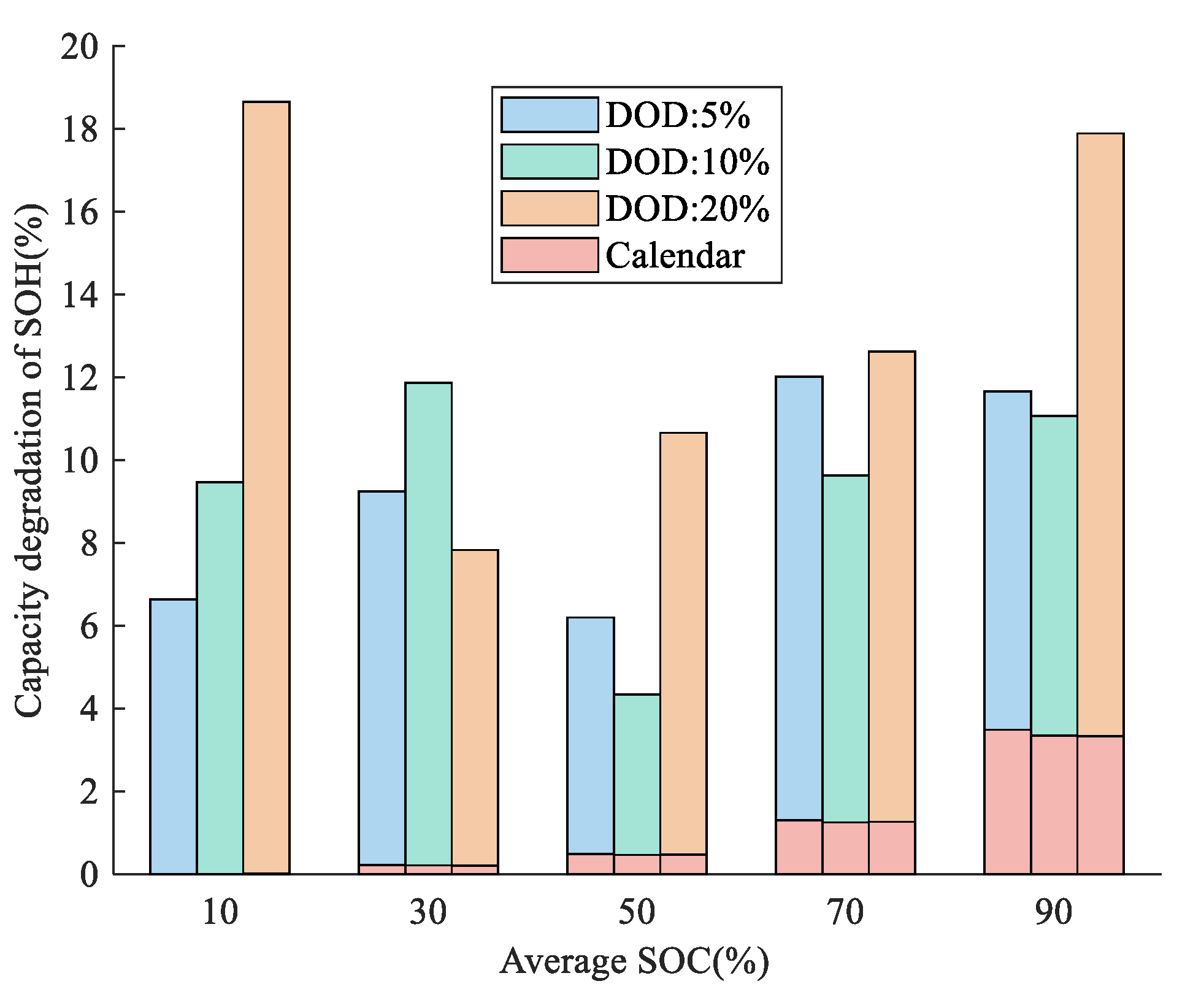
Figure 5 shows the cells’ average capacity degradation of each cycle after 660 equivalent cycles at different average SOC with three DOD ranges (5, 10, 20%). The results of different SOC ranges demonstrate that the batteries cycled in high and low SOC intervals will sustain the most capacity loss. The maximum capacity loss occurs in the 0–20% SOC cycle, which is 18.65%, followed by the 80–100% SOC cycle, which is about 17.88%. A minimum in aging is detected for the cells cycled around 30% and 50% average SOC. The cells cycled at 50% average SOC with 10% DOD have only experienced a capacity loss of 4.34% after prolonged cycling. Therefore, operating within 30–70% SOC is more beneficial to the NCM batteries with other conditions being equal. Additionally, this result demonstrates that if the grid application is performed around 45–55% SOC for the battery, the negative effect of the extra charging and discharging may be alleviated to the least. With the increase in average SOC, the ratio of calendar life to total aging increased from 1.77% in the 20–40% SOC cycle to 18.6% in the 80–100% SOC cycle. The proportion of calendar and cyclical aging indicated that the battery cycled under high SOC ranges will suffer more from the deterioration of thermodynamic property, while the bottom SOC interval cycling will lead to more kinetic performance degradation, which is also consistent with the phenomenon that occurred in [25].
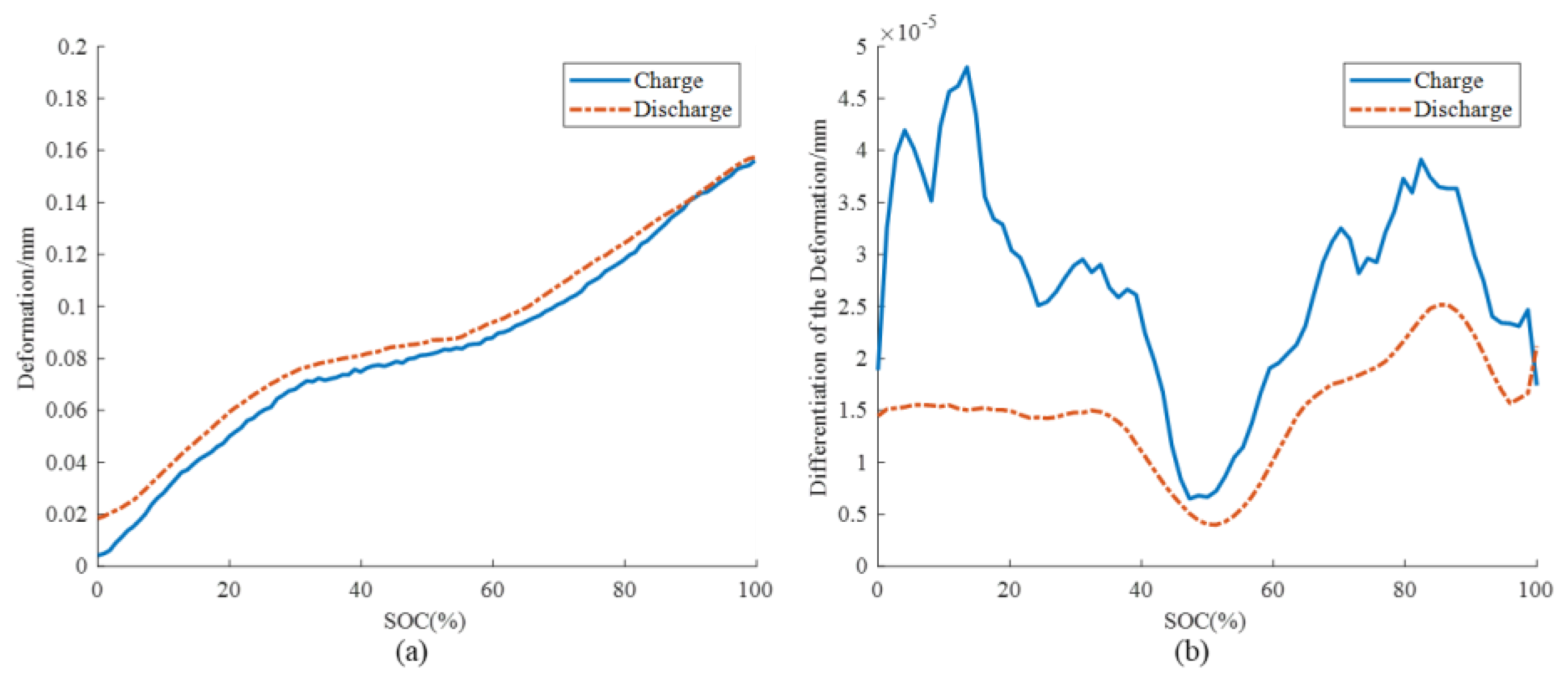
To better understand the mechano-electrochemical coupling characteristics, we have also conducted the battery deformation test, and the non-destructive test devices are described in [52]. The results are shown in Figure 6, which can be used to explain to some extent why the SOC range has a significant impact on the battery aging results. There is the highest rise of deformation rate around 10% SOC during the charging process. The intercalation and deintercalation of the lithium-ions will cause more severe repetitive stress and strain to the electrode, and the accumulation of the microscopic structural damage will lead to more fracture and loss of active material (LAM). This phenomenon is consistent with the fact that the cyclical loss of capacity within 0–20% SOC is higher than that of 80%-100% SOC. Additionally, the battery deformation cycled within 40–60% SOC experienced little change, accordant with the lowest capacity loss in this interval.

3.1.2. Different DOD and C-Rate

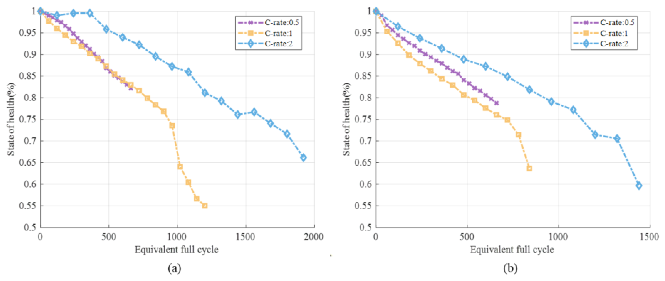
As presented in Figure 7, the battery cycling at 80% DOD reaches 80% SOH faster than the battery cycling at 40% after being transferred to the same equivalent cycles (the slope of the battery capacity decay path becomes larger), which means that the cycle average degradation in the range of 10–90% is greater than that in the range of 30–70%. This is in line with the prior, since the particle cracking, SEI film growth, and other side reactions, induced by kinetic and thermodynamic processes, are more moderate within the middle interval of the SOC range.
Under 40 and 80% DOD, contrary to expectations, the higher charging rates have led to a less severe battery capacity drop. In effect, such results are also acquired in some previous studies. The research in [34] found that C-rate will have little effect on aging results if the temperature is maintained strictly constant. It is observed in [39] that at 20 °C, cells cycled under 1 C and 2 C decay slower than those under 0.5 C. Additionally, the rise of temperature from 20 to 34 °C has improved the battery life under several high C-rates. This phenomenon may be explained by the improvement of calendar aging under high C-rates [28]. According to the experimental programs, under the same equivalent cycle (the same Ah-throughput), the test time at the 2 C rate is half and a quarter of the time at the 1 C and 0.5 C rates, respectively. Therefore, for this type of NCM power battery, the reduction in battery shelf time will improve the calendar life, surpassing the cyclic damage caused by higher discharging currents. In this way, the battery life may be extended under higher C-rates after the same equivalent full cycles (EFCs). More investigation could be done on this uncommon trend of degradation induced by C-rate for such cells with large capacities. In addition, it can be seen that under the 1 C rate experiment in Figure 7a, the battery experienced a ‘sharp drop’ in capacity after 1000 equivalent cycles. There were gray attachments on the negative electrode surface that cannot be cleaned off in Figure 2e. From our previous characterization, such morphology is usually caused by lithium plating [21].
The results of cycling the cells at different DOD ranges at the same current are plotted in Figure 8. Overall, the capacity loss increases as the DOD increases. Surprisingly, the results show that the capacity loss is non-linear as a function of DOD, and under a higher C-rate, the transition DOD becomes larger. The DOD of 40 and 60% with 1 C charging current are close to each other and this similarity occurs for DOD of 60 and 80% under 2 C charging rate. Such similar non-linear relation of DOD is explained by diffusion to/from the overhang/overlap or other unknown phenomena in [27]. After 400 equivalent cycles, the battery capacity has dived, and it is suspected that the battery has Lithium precipitation occurred. For the ~80% DOD cells under 1 C and 2 C, the battery SOH has experienced a ‘sharp drop’ after prolonged cycling, indicating that the batteries are supposed to be charged at a milder working condition in reality.

3.2. Aging Mechanism Identification

We have selected six typical sets of the above experiments to distinguish the different internal degradation mechanisms. First, incremental capacity (IC) analysis is employed to qualitatively analyze the internal degradation processes of the cathode and anode inside the batteries [53]. The LEAN method in [54] is used to calculate the differentiation of the voltage curve dQ/dV, which counts the numbers at the sampling levels to avoid the new errors introduced by curve fitting. The three peaks, denoted as ①*II, ②*II, and ⑤*II, are corresponding to the phase transformation of the electrode and the main aging factors. Peak ①*II indicates the loss of lithium-ion inventory (LLI), and the loss of active material (LAM) is regarded to change the shape and height of Peak ②*II and ⑤*II [55]. Figure 9a–c compares different SOC ranges with the same charging current. The cell cycled at 0–20% SOC in the early stage mainly decays with the loss of active materials, followed by a small amount of LLI, while 80–100% SOC intervals have experienced a significant increase in internal resistance. It can be seen from Figure 9d,e that, when DOD exceeds 40%, the loss of active material (LAM) and LLI are more significant at 1 C and 2 C charging currents. In the range of 40–60% SOC, the battery capacity remains virtually constant under different C-rates. Even a large charging current at 40–60% SOC only led to limited LAM, in accordance with the deformation curve mentioned above. When the C-rate is increased from 0.5 C to 2 C, the SOH after 500 cycles decreases only from 95 to 93%, and the growth of LAM shown by the IC curve is not obviously depicted in Figure 9b,e. This suggests that for some grid-connected applications with severe operating conditions fluctuations, the battery working range should be controlled within the 40–60% SOC, so as to minimize the damage to the electrode microstructure caused by repeated charge and discharge stress changes.
The voltage parameter reconstruction (VPR) described in Section 2.2.2 is carried out to quantitatively analyze the aging mechanisms. In order to obtain the positive and negative electrode potential curves, a fresh pouch battery was disassembled. Figure 10a shows the comparison of the evolution of the negative terminal capacity Cn between the proposed RF-VPR method and the original VPR method. With the increase of the EFC, Cn gradually decreases, and the identification results of the two methods are similar under different cycling conditions, indicating the high simulation accuracy of the proposed method. Meanwhile, since the number of parameters to be calibrated has declined from five to two, the RF-VPR has performed priority in faster convergence speed with the same heuristic algorithm. As shown in Figure 10c, compared with the original VPR results, RF-VPR has reached a smaller RMSE more rapidly. For instance, the purple solid line of RF-VPR drops to RMSE < 3mV after 40 iterations while the dotted line of VPR remains around 4mV. Concerning the randomness in the initialization of the algorithm, the results fluctuate to some extent. However, in general, the proposed RF-VPR has better accuracy and convergence rate due to having fewer parameters to be identified. Additionally, the reconstruction voltage curve can be used to explain why the repeated 0–20% cycling has caused serious battery degradation. As shown by the OCV curve of the typical battery in Figure 10b, under the low SOC range below 20%, the structural change of the graphite surface is mainly in the range of 0 ≤ x < 0.19 (LixC), and when operating in this range, the SEI film of the battery is prone to fatigue damage, resulting in aggravated LLI.
The evolution of indicators for LAM and LLI is presented in Figure 11. The loss of active material dominates the side reactions for the 0–20% cycling, and negative capacity decreases faster after 500 cycles. As shown in Figure 11c, with the increase of cycle numbers, the total amount of lithium ions available inside also decreases steadily. It can be seen that at the early stage of aging, LLI does not occupy a dominant position. With the increase in cycle times, LLI gradually increases. After 600 cycles, the negative and positive capacity at 2C and 30–70% SOC decreases rapidly, revealing that LAM is the major reason that caused the NCM battery degradation cycle in this region. The decay of the capacity of positive and negative electrodes and the amount of available lithium ions at the 2C magnification of 40–60% SOC is the smallest, which corresponds to the previous results that the battery decay is smaller at the average SOC of 50% under a narrow DOD.

4. Map Figure and V2G Conditions

4.1. Nature of Aging and Quantification of Degradation

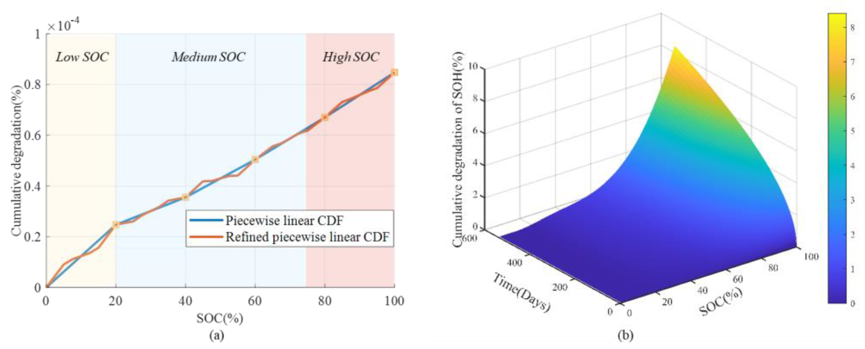
The cumulative degradation function (CDF) of the experimental results is depicted in Figure 12a. The detailed methodology is illustrated in Section 2.2.3. In this paper, since we have carried out experiments on more refined SOC intervals including 5 and 10% DOD, the CDF is acquired by more subdivided intervals. As shown by Figure 12a, the piecewise linear CDF represents the battery cyclical loss (8.47 × 10⁻⁵ % SOH) after charging from 0 to 100% SOC for one time. The charging and discharging processes are assumed to impact equally on the tested batteries. A refined piecewise linear cumulative degradation function is established based on the experiment of cells cycled under different average SOC and DOD ranges. Under the same average SOC, the varied DOD will lead to differences. The slope of the refined CDF curve has a turning point to become smaller at the 5% horizontal coordinate point, corresponding to the experimental results that the decay within the 0–20% cycle is much greater than that of the 5–15% SOC range shown in Figure 5. Therefore, the more refined piecewise linear CDF can reveal more detailed aging characteristics and paths influenced by the SOC range. In Figure 12b, the CDF functions under different charging currents are compared.
It is found that the charging currents have limited influence on the average capacity fade after the same equivalent cycles when the C-rate is below 1 C. The higher C-rate caused more degradation mainly because it led to more Ah throughput in the same time period. Considering that V2G is usually implemented under slow charging and discharging operations (<0.5 C) for safety, the SOC and DOD factors are priorities when designing the charging strategies. Figure 12b exhibits the calendar aging function based on the experimental data that after 1.5 years, the battery stored at 100% SOC at 25 °C has lost 7% SOH. The calendar aging shows a 1/2 power function of the shelf-time and rapidly decreases with the decrease of SOC. The tests show that the batteries at 10, 30, and 50% SOC have shown very limited degradation after 1.5 years. As a matter of fact, if the batteries are stored at high SOC ranges, the calendar aging may exceed the cyclic aging to become the main degradation factor. Such results regarding charging rate and calendar aging are similar to some previous literature. As for C-rates under 1 C, the impact of SOC on degradation is much larger than that of the C-rate [56]. The charging power rising from 1.5 kW to 7.6 kW has not led to a significant difference in battery aging change, as discussed in [38]. The 50 Ah NCM pouch cells are studied in [57] and the results show that calendar aging is the dominant indicator compared to cyclic aging.

4.2. V2G Conditions and Battery Aging Results

Based on the statistics and travel rules in Section 2.2.3, four V2G and four unmanaged charging (V0G) profiles are designed, as shown in Figure 13. According to the charging behavior survey, some car owners are accustomed to charging after leaving work every day, which keeps the SOC in a high range. For realistic usage, in more than 60% of the cases, EV batteries are kept higher than 70% SOC, and 25% of the users prefer to maintain the SOC within 90–100% [58,59]. Some drivers charge every few days, while some don’t charge until the SOC drops below 20% [60]. Therefore, to reflect these habits, profiles of EVs that do not participate in V2G are mainly designed by four lower limits of SOC, namely, 20, 40, 80, and 90%. EVs participating in V2G, on the other hand, discharge to sell electricity at peak times to earn revenue, while meeting the demand for two trips per day. The four working conditions of V2G are designed by the lowest SOC (20, 40, 65, and 80%) after discharging by V2G and traveling each day.
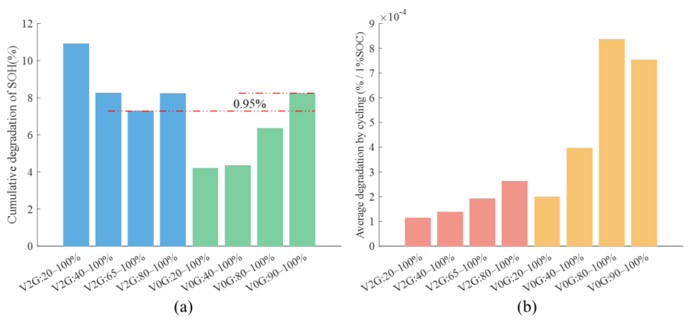
Substituting the charging conditions into the cyclic CDF equation in Figure 12 and the map of calendar aging, the loss of EV battery capacities with time can be obtained, as shown in Figure 14. Among them, the batteries used in the 90–100% SOC interval have the highest calendar aging, which has decayed by 8% in 1.5 years, most of which is thermodynamic degradation caused by staying at high SOC. Therefore, after applying V2G, although the cyclic aging is increased, the usage range of SOC is greatly improved. As a result, except for the excessive discharge of 20–100% V2G, the rest of the V2G scenarios are all better than the V0G scenario at 90–100% SOC.
Figure 15a shows the final decay rates of the battery SOH for various scenarios. With the increase of V2G depth of discharge, there is a ‘trade-off’ relationship between reducing the average SOC to improve the calendar life and increasing the cyclic degradation. The model of this work shows that discharging the SOC by 25% from 90% to 65% through V2G is an optimal choice, which can even extend the battery life. However, if the EV is discharged to 20% SOC by V2G every day, the capacity loss will increase to 11%, much larger than a normal EV with SOC within 20–100% which is charged every four days. Therefore, the V2G operation is not supposed to be conducted under a large DOD. Figure 15b shows the average degradation by cycling for 1% SOC, which divides the total battery decay by the total discharged power. With the increase of V2G discharge DOD, although the total amount of capacity loss increases, the average degradation caused by unit discharging keeps declining. And the unit degradation of V2G is generally lower than that of V0G mode. From this point of view, more work should be done to study the relationship between the degradation cost and the profit earned from the grid company to optimize the charging and discharging strategies.

5. Conclusions

In this paper, the comprehensive degradation study is performed on the experimental matrix of 33 commercial 24 Ah Li(NiMnCo)O2 pouch batteries. The average SOC, DOD, and C-rate are the main factors considered and used to establish the non-linear degradation model with calendar and cyclical aging. An improved non-destructive diagnostic method, the RF-VPR method is proposed to quantify the different aging mechanisms. Finally, the battery degradation costs under different V2G charging and discharging profiles are evaluated based on the experimental results and the CDF.
The main findings and conclusions are summarized as: (1) the average cycling SOC ranges have a great impact on the battery life. Operating within 30–70% SOC is more beneficial to the NCM batteries, either too high or low SOC intervals will result in extremely increased capacity loss. The proportion of calendar aging is more than 20% of the total battery decay within the 80–100% SOC.; (2) The DOD range and C-rate have shown non-linear function with battery degradation due to the combination of thermodynamic and kinetic processes. Under 40–60% SOC, the battery capacity remains virtually constant under different C-rates, indicating that the more intense grid application can be applied in this SOC interval; (3) the RF-VPR converges faster than the original VPR while maintaining high reconstruction accuracy. The incremental capacity (IC) analysis is combined together to show the evolution of aging mechanisms. The cell cycled at 0–20% SOC first mainly decays with the loss of active materials, followed by LLI, while 80–100% SOC intervals have experienced an increase in internal resistance. When DOD exceeds 40%, LAM and LLI are more significant at 1 C and 2 C charging currents. (4) A Refined piecewise linear CDF is established based on the experimental results and applied to analyze the battery aging under V2G profiles. The results show that V2G may extend the battery life under certain scenarios. As for the EV cycled at 90–100% SOC, by introducing V2G to decline the minimum SOC to 65%, the battery degradation has decreased 0.95% compared with the case without V2G after 1.5 years. However, if the EV is discharged to 20% SOC by V2G every day, the capacity loss will increase to 11%, much larger than a normal EV with SOC within 20–100% which is charged every four days. This indicates that V2G operation should be controlled within a moderate DOD.
Future work includes: (1) multi-objective optimization of the degradation cost and the profit earned from the grid to design the optimal charging and discharging strategies; (2) more detailed battery modeling to reflect the more dynamic conditions like vehicle start and stop; (3) introduction of other realistic application factors, i.e., the temperature of different seasons and the effect of temperature on the varied battery aging paths, and the inconsistency of cells in the battery pack.

Author Contributions

Conceptualization, Y.W. and Y.Q.; methodology, Y.W. and K.P.; software, Y.W., K.P. and Y.Y.; validation, X.H., L.L., Y.L. and H.W.; writing—original draft preparation, Y.W., K.P., C.X. and Y.Y.; writing—review and editing, Y.W., K.P., Y.Y. and X.H.; visualization, Y.W., K.P. and Y.Y.; supervision, Y.Z., H.W. and M.O.; project administration, M.O.; funding acquisition, M.O. All authors have read and agreed to the published version of the manuscript.

Funding

This research was funded by the Ministry of Science and Technology of China under Grant No. 2019YFE0100200, the National Natural Science Foundation of China (NSFC) under Grant No. 52177217, and Grant No. 52037006, Beijing Natural Science Foundation under the Grant No. 3212031 and Tsinghua-Toyota Joint Research Institute Cross-discipline Program.

Institutional Review Board Statement

Not applicable.

Informed Consent Statement

Not applicable.

Data Availability Statement

The data is available through appropriate requests.

Acknowledgments

We want to thank the State Grid EV Service company for their support.

Conflicts of Interest

The authors declare no conflict of interest.

Abbreviations

BESSbattery energy storage system
BEVbattery electric vehicle
C-ratecharging rate
CDFcumulative degradation function
DODdepth of discharge
EFCequivalent full cycle
ECethylene carbonate
EMCethyl methyl carbonate
EVelectric vehicle
HPPChybrid pulse power characteristic
ICincremental capacity
LAMloss of active material
LLIloss of lithium-ion inventory
LFPgraphite-LiFePO4 battery
OCVopen circuit voltage
PCpersonal computer
NCMgraphite-Li(NiMnCo)O2 battery
RErenewable energy
RMSEroot-mean-square error
RF-VPRreduced freedom voltage parameter reconstruction
SEIsolid electrolyte interface
SEMscanning electron microscope
SOCstate of charge
SOHstate of health
SPMsingle particle model
VPRvoltage parameter reconstruction
V0Gunmanaged charging
V2Gvehicle-to-grid

Variables

C p capacities of the cathode, Ah
C n capacities of the anode, Ah
C r e relative capacity of the positive and negative electrode, Ah
C battery capacity of electric vehicle, Ah
E S O C t r a v e l SOC at the ending of travel, %
f D F piecewise linear degradation density function
F C D F piecewise linear degradation density accumulation function
h power consumption per hundred kilometers
I t current of the battery, A
K rate coefficient
P c h a charging power of electric vehicle, kW
P t c h a EV charging power, kW
P t d c h EV discharge power, kW
q l o s s c a l e n d a r unit calendar aging, %
Q l o s s c a l e n d a r total calendar aging, %
Q l o s s C y c l i n g total cyclic aging, %
Q l o s s b a t total capacity loss, %
Q Li the sum of the amount of lithium in the positive electrode and that in the negative electrode, Ah
R internal resistance, Ω
S O H i , c o r temperature corrected SOH, %
S S O C t r a v e l SOC at the beginning of travel, %
t time, year
T i average temperature, °C
T temperature, °C
t r a v e l r a n g e travel mileage, km
U p r e f positive equilibrium potential, V
U n r e f negative equilibrium potential, V
V ˜ ( t )   battery terminal voltage, V
V n o m nominal voltage of the battery, V
x 0 lithium-ion fraction of the battery at the beginning of charging of the anode
y 0 lithium-ion fraction of the battery at the beginning of charging of the cathode
Δ p relative position of the positive and negative curves, Ah
η charging efficiency, %
δ 20 % , k C y c 20% DOD capacity loss, %
δ 10 % , k C y c 10% DOD capacity loss, %
δ 5 % , k C y c 5% DOD capacity loss, %

References

  1. Wei, Y.; Han, X.; Lu, L.; Wang, H.; Ouyang, M. The potential and technical prospects of energy storage by vehicle to grid and hydrogen utilization under carbon neutrality target. Automot. Eng. 2022, 44, 449–464. [Google Scholar] [CrossRef]
  2. Wei, Y.; Huang, H.; Han, X.; Lu, L.; Ouyang, M.; Pang, K.; Qin, Y. Whole-system Potential and Benefit of Energy Storage by Vehicle-to-grid (V2G) under Carbon Neutrality Target in China. In Proceedings of the 2022 IEEE 5th International Electrical Energy Conference, Nangjing, China, 27–29 May 2022; pp. 4006–4012. [Google Scholar] [CrossRef]
  3. Qin, Y.; Chen, X.; Tomaszewska, A.; Chen, H.; Wei, Y.; Zhu, H.; Li, Y.; Cui, Z.; Huang, J.; Du, J.; et al. Lithium-ion batteries under pulsed current operation to stabilize future grids. Cell Rep. Phys. Sci. 2022, 3, 100708. [Google Scholar] [CrossRef]
  4. Fachrizal, R.; Shepero, M.; van der Meer, D.; Munkhammar, J.; Widén, J. Smart charging of electric vehicles considering photovoltaic power production and electricity consumption: A review. eTransportation 2020, 4, 100056. [Google Scholar] [CrossRef]
  5. Morsalin, S.; Haque, A.; Mahmud, A. Machine to machine performance evaluation of grid-integrated electric vehicles by using various scheduling algorithms. eTransportation 2020, 3, 100044. [Google Scholar] [CrossRef]
  6. Li, D.; Zouma, A.; Liao, J.T.; Yang, H.T. An energy management strategy with renewable energy and energy storage system for a large electric vehicle charging station. eTransportation 2020, 6, 100076. [Google Scholar] [CrossRef]
  7. Yang, Q.; Li, D.; An, D.; Yu, W.; Fu, X.; Yang, X.; Zhao, W. Towards Incentive for Electrical Vehicles Demand Response with Location Privacy Guaranteeing in Microgrids. IEEE Trans. Dependable Secur. Comput. 2022, 19, 131–148. [Google Scholar] [CrossRef]
  8. Darcovich, K.; Laurent, T.; Ribberink, H. Improved prospects for V2X with longer range 2nd generation electric vehicles. eTransportation 2020, 6, 100085. [Google Scholar] [CrossRef]
  9. Schwenk, K.; Meisenbacher, S.; Briegel, B.; Harr, T.; Hagenmeyer, V.; Mikut, R. Integrating Battery Aging in the Optimization for Bidirectional Charging of Electric Vehicles. IEEE Trans. Smart Grid. 2021, 12, 5135–5145. [Google Scholar] [CrossRef]
  10. Gonzalez Venegas, F.; Petit, M.; Perez, Y. Plug-in behavior of electric vehicles users: Insights from a large-scale trial and impacts for grid integration studies. eTransportation 2021, 10, 100131. [Google Scholar] [CrossRef]
  11. Darcovich, K.; Recoskie, S.; Ribberink, H.; Michelet, C. The impact of V2X service under local climatic conditions within Canada on EV durability. eTransportation 2021, 9, 100124. [Google Scholar] [CrossRef]
  12. Ahmadian, A.; Sedghi, M.; Mohammadi-Ivatloo, B.; Elkamel, A.; Aliakbar Golkar, M.; Fowler, M. Cost-Benefit Analysis of V2G Implementation in Distribution Networks Considering PEVs Battery Degradation. IEEE Trans. Sustain. Energy 2018, 9, 961–970. [Google Scholar] [CrossRef]
  13. Gao, S.; Li, H.; Jurasz, J.; Dai, R. Optimal Charging of Electric Vehicle Aggregations Participating in Energy and Ancillary Service Markets. IEEE J. Emerg. Sel. Top Ind. Electron. 2021, 3, 270–278. [Google Scholar] [CrossRef]
  14. Zhang, Y.; Sun, J.; Wu, C. Vehicle-to-Grid Coordination via Mean Field Game. IEEE Control Syst. Lett. 2022, 6, 2084–2089. [Google Scholar] [CrossRef]
  15. Moghaddam, V.; Ahmad, I.; Habibi, D.; Masoum, M.A.S. Dispatch management of portable charging stations in electric vehicle networks. eTransportation 2021, 8, 100112. [Google Scholar] [CrossRef]
  16. Unterluggauer, T.; Rich, J.; Andersen, P.B.; Hashemi, S. Electric vehicle charging infrastructure planning for integrated transportation and power distribution networks: A review. eTransportation 2022, 12, 100163. [Google Scholar] [CrossRef]
  17. Hussain, A.; Bui, V.H.; Kim, H.M. Optimal Sizing of Battery Energy Storage System in a Fast EV Charging Station Considering Power Outages. IEEE Trans. Transp. Electrif. 2020, 6, 453–463. [Google Scholar] [CrossRef]
  18. Maheshwari, A.; Paterakis, N.G.; Santarelli, M.; Gibescu, M. Optimizing the operation of energy storage using a non-linear lithium-ion battery degradation model. Appl. Energy 2020, 261, 114360. [Google Scholar] [CrossRef]
  19. Cao, Y.; Li, D.; Zhang, Y.; Chen, X. Joint Optimization of Delay-Tolerant Autonomous Electric Vehicles Charge Scheduling and Station Battery Degradation. IEEE Internet Things J. 2020, 7, 8590–8599. [Google Scholar] [CrossRef]
  20. Ebrahimi, M.; Rastegar, M.; Mohammadi, M.; Palomino, A.; Parvania, M. Stochastic Charging Optimization of V2G-Capable PEVs: A Comprehensive Model for Battery Aging and Customer Service Quality. IEEE Trans. Transp. Electrif. 2020, 6, 1026–1034. [Google Scholar] [CrossRef]
  21. Wei, Y.; Wang, S.; Han, X.; Lu, L.; Li, W.; Zhang, F.; Ouyang, M. Toward more realistic microgrid optimization: Experiment and high-efficient model of Li-ion battery degradation under dynamic conditions. eTransportation 2022, 14, 100200. [Google Scholar] [CrossRef]
  22. Wei, Y.; Han, T.; Wang, S.; Qin, Y.; Lu, L.; Han, X.; Ouyang, M. An efficient data-driven optimal sizing framework for photovoltaics-battery-based electric vehicle charging microgrid. J Energy Storage 2022, 55, 105670. [Google Scholar] [CrossRef]
  23. Han, X.; Lu, L.; Zheng, Y.; Feng, X.; Li, Z.; Li, J.; Ouyang, M. A review on the key issues of the lithium ion battery degradation among the whole life cycle. eTransportation 2019, 1, 100005. [Google Scholar] [CrossRef]
  24. Kebede, A.A.; Hosen, M.S.; Messagie, M.; Behabtu, H.A.; Jemal, T.; Van Mierlo, J.; Coosemans, T.; Berecibar, M. Development of a lifetime model for large format nickel-manganese-cobalt oxide-based lithium-ion cell validated using a real-life profile. J. Energy Storage 2022, 50, 104289. [Google Scholar] [CrossRef]
  25. Gao, Y.; Jiang, J.; Zhang, C.; Zhang, W.; Jiang, Y. Aging mechanisms under different state-of-charge ranges and the multi-indicators system of state-of-health for lithium-ion battery with Li(NiMnCo)O2 cathode. J. Power Sources 2018, 400, 641–651. [Google Scholar] [CrossRef]
  26. Jiang, J.; Gao, Y.; Zhang, C.; Zhang, W.; Jiang, Y. Lifetime Rapid Evaluation Method for Lithium-Ion Battery with Li(NiMnCo)O2 Cathode. J. Electrochem. Soc. 2019, 166, A1070–A1081. [Google Scholar] [CrossRef]
  27. Gauthier, R.; Luscombe, A.; Bond, T.; Bauer, M.; Johnson, M.; Harlow, J.; Louli, A.J.; Dahn, J.R. How do Depth of Discharge, C-rate and Calendar Age Affect Capacity Retention, Impedance Growth, the Electrodes, and the Electrolyte in Li-Ion Cells? J. Electrochem. Soc. 2022, 169, 020518. [Google Scholar] [CrossRef]
  28. Ecker, M.; Nieto, N.; Käbitz, S.; Schmalstieg, J.; Blanke, H.; Warnecke, A.; Sauer, D.U. Calendar and cycle life study of Li(NiMnCo)O2-based 18650 lithium-ion batteries. J. Power Sources 2014, 248, 839–851. [Google Scholar] [CrossRef]
  29. Zhu, J.; Knapp, M.; Sørensen, D.R.; Heere, M.; Darma, M.S.D.; Müller, M.; Mereacre, L.; Dai, H.; Senyshyn, A.; Wei, X.; et al. Investigation of capacity fade for 18650-type lithium-ion batteries cycled in different state of charge (SoC) ranges. J. Power Sources 2021, 489, 229422. [Google Scholar] [CrossRef]
  30. Liu, S.; Wang, J.; Liu, H.; Liu, Q.; Tang, J.; Li, Z. Battery degradation model and multiple-indicators based lifetime estimator for energy storage system design and operation: Experimental analyses of cycling-induced aging. Electrochim. Acta 2021, 384, 138294. [Google Scholar] [CrossRef]
  31. Lucu, M.; Azkue, M.; Camblong, H.; Martinez-Laserna, E. Data-Driven Nonparametric Li-Ion Battery Ageing Model Aiming at Learning from Real Operation Data: Holistic Validation with Ev Driving Profiles. In Proceedings of the ECCE 2020—IEEE Energy Conversion Congress Exposition, Detroit, MI, USA, 11–15 October 2020; Volume 30, pp. 5600–5607. [Google Scholar] [CrossRef]
  32. Preger, Y.; Barkholtz, H.M.; Fresquez, A.; Campbell, D.L.; Juba, B.W.; Romàn-Kustas, J.; Ferreira, S.R.; Chalamala, B. Degradation of Commercial Lithium-Ion Cells as a Function of Chemistry and Cycling Conditions. J. Electrochem. Soc. 2020, 167, 120532. [Google Scholar] [CrossRef]
  33. Jia, X.; Zhang, C.; Wang, L.Y.; Zhang, L.; Zhang, W. The Degradation Characteristics and Mechanism of Li[Ni0.5Co0.2Mn0.3]O2 Batteries at Different Temperatures and Discharge Current Rates. J. Electrochem. Soc. 2020, 167, 020503. [Google Scholar] [CrossRef]
  34. Barcellona, S.; Piegari, L. Effect of current on cycle aging of lithium ion batteries. J. Energy Storage 2020, 29, 101310. [Google Scholar] [CrossRef]
  35. Dubarry, M.; Devie, A.; McKenzie, K. Durability and reliability of electric vehicle batteries under electric utility grid operations: Bidirectional charging impact analysis. J. Power Sources 2017, 358, 39–49. [Google Scholar] [CrossRef]
  36. Uddin, K.; Jackson, T.; Widanage, W.D.; Chouchelamane, G.; Jennings, P.A.; Marco, J. On the possibility of extending the lifetime of lithium-ion batteries through optimal V2G facilitated by an integrated vehicle and smart-grid system. Energy 2017, 133, 710–722. [Google Scholar] [CrossRef]
  37. Petit, M.; Prada, E.; Sauvant-Moynot, V. Development of an empirical aging model for Li-ion batteries and application to assess the impact of Vehicle-to-Grid strategies on battery lifetime. Appl. Energy 2016, 172, 398–407. [Google Scholar] [CrossRef]
  38. Jafari, M.; Gauchia, A.; Zhao, S.; Zhang, K.; Gauchia, L. Electric Vehicle Battery Cycle Aging Evaluation in Real-World Daily Driving and Vehicle-to-Grid Services. IEEE Trans. Transp. Electrif. 2017, 4, 122–134. [Google Scholar] [CrossRef]
  39. Carmeli, M.S.; Toscani, N.; Mauri, M. Electrothermal Aging Model of Li-Ion Batteries for Vehicle-to-Grid Services Evaluation. Electronics 2022, 11, 1042. [Google Scholar] [CrossRef]
  40. Farzin, H.; Fotuhi-Firuzabad, M.; Moeini-Aghtaie, M. A Practical Scheme to Involve Degradation Cost of Lithium-Ion Batteries in Vehicle-to-Grid Applications. IEEE Trans. Sustain. Energy 2016, 7, 1730–1738. [Google Scholar] [CrossRef]
  41. Bhoir, S.; Caliandro, P.; Brivio, C. Impact of V2G service provision on battery life. J. Energy Storage 2021, 44, 103178. [Google Scholar] [CrossRef]
  42. Bakeer, A.; Chub, A.; Shen, Y.; Sangwongwanich, A. Reliability analysis of battery energy storage system for various stationary applications. J. Energy Storage 2022, 50, 104217. [Google Scholar] [CrossRef]
  43. Gao, Y.; Yang, S.; Jiang, J.; Zhang, C.; Zhang, W.; Zhou, X. The Mechanism and Characterization of Accelerated Capacity Deterioration for Lithium-Ion Battery with Li(NiMnCo)O2 Cathode. J. Electrochem. Soc. 2019, 166, A1623–A1635. [Google Scholar] [CrossRef]
  44. Jin, L.; Sun, Z.; Liu, Z.; Li, J.; Yang, M. Simulation Study on State of Charge Estimation of Lithium-ion Battery at Different Temperatures. Qiche Gongcheng Automot. Eng. 2019, 41, 590–598. [Google Scholar] [CrossRef]
  45. Li, K.; Zhou, P.; Lu, Y.; Han, X.; Li, X.; Zheng, Y. Battery life estimation based on cloud data for electric vehicles. J. Power Sources 2020, 468, 228192. [Google Scholar] [CrossRef]
  46. Han, X.; Ouyang, M.; Lu, L.; Li, J.; Zheng, Y.; Li, Z. A comparative study of commercial lithium ion battery cycle life in electrical vehicle: Aging mechanism identification. J. Power Sources 2014, 251, 38–54. [Google Scholar] [CrossRef]
  47. Hao, X.; Wang, H.; Lin, Z.; Ouyang, M. Seasonal effects on electric vehicle energy consumption and driving range: A case study on personal, taxi, and ridesharing vehicles. J. Clean. Prod. 2020, 249, 119403. [Google Scholar] [CrossRef]
  48. Redondo-Iglesias, E.; Venet, P.; Pelissier, S. Calendar and cycling ageing combination of batteries in electric vehicles. Microelectron. Reliab. 2018, 88–90, 1212–1215. [Google Scholar] [CrossRef] [Green Version]
  49. Harlow, J.E.; Ma, X.; Li, J.; Logan, E.; Liu, Y.; Zhang, N.; Ma, L.; Glazier, S.L.; Cormier, M.M.E.; Genovese, M.; et al. A Wide Range of Testing Results on an Excellent Lithium-Ion Cell Chemistry to be used as Benchmarks for New Battery Technologies. J. Electrochem. Soc. 2019, 166, A3031–A3044. [Google Scholar] [CrossRef]
  50. Bloom, I.; Jones, S.A.; Polzin, E.G.; Battaglia, V.S.; Henriksen, G.L.; Motloch, C.G.; Wright, R.B.; Jungst, R.G.; Case, H.L.; Doughty, D.H. Mechanisms of impedance rise in high-power, lithium-ion cells. J. Power Sources 2002, 111, 152–159, Erratum in J. Power Sources 2003, 114, 180. [Google Scholar] [CrossRef]
  51. Ploehn, H.J.; Ramadass, P.; White, R.E. Solvent Diffusion Model for Aging of Lithium-Ion Battery Cells. J. Electrochem. Soc. 2004, 151, A456. [Google Scholar] [CrossRef] [Green Version]
  52. Xie, Y.; Wang, S.; Li, R.; Ren, D.; Yi, M.; Xu, C.; Han, X.; Lu, L.; Friess, G.; Offer, G.; et al. Inhomogeneous degradation induced by lithium plating in a large-format lithium-ion battery. J. Power Sources 2022, 542, 231753. [Google Scholar] [CrossRef]
  53. Zhang, Y.; Xiong, R.; He, H.; Qu, X.; Pecht, M. Aging characteristics-based health diagnosis and remaining useful life prognostics for lithium-ion batteries. eTransportation 2019, 1, 100004. [Google Scholar] [CrossRef]
  54. Feng, X.; Merla, Y.; Weng, C.; Ouyang, M.; He, X.; Liaw, B.Y.; Santhanagopalan, S.; Li, X.; Liu, P.; Lu, L.; et al. A reliable approach of differentiating discrete sampled-data for battery diagnosis. eTransportation 2020, 3, 100051. [Google Scholar] [CrossRef]
  55. Dubarry, M.; Truchot, C.; Liaw, B.Y. Synthesize battery degradation modes via a diagnostic and prognostic model. J. Power Sources 2012, 219, 204–216. [Google Scholar] [CrossRef]
  56. Han, S.; Aki, H.; Han, S. A practical battery wear model for electric vehicle charging applications. IEEE Power Energy Soc. Gen. Meet. 2013, 113, 1100–1108. [Google Scholar] [CrossRef]
  57. Rücker, F.; Schoeneberger, I.; Wilmschen, T.; Chahbaz, A.; Dechent, P.; Hildenbrand, F.; Barbers, E.; Kuipers, M.; Figgener, J.; Sauer, D.U. A Comprehensive Electric Vehicle Model for Vehicle-to-Grid Strategy Development. Energies 2022, 15, 4186. [Google Scholar] [CrossRef]
  58. Ben-Marzouk, M.; Pelissier, S.; Clerc, G.; Sari, A.; Venet, P. Generation of a Real-Life Battery Usage Pattern for Electrical Vehicle Application and Aging Comparison with the WLTC Profile. IEEE Trans. Veh. Technol. 2021, 70, 5618–5627. [Google Scholar] [CrossRef]
  59. Wei, Y.; Wang, S.; Qin, Y.; Han, T.; Tao, L.; Wang, J.; Lu, L.; Ouyang, M.; Han, X. A Novel Data Augmentation and Swift Optimal Sizing Framework for PV-based EV Charging Microgrid. In Proceedings of the 2021 IEEE 4th International Electrical Energy Conference, Wuhan, China, 28–30 May 2021; pp. 1–6. [Google Scholar] [CrossRef]
  60. Qin, Y.; Han, X.; Wei, Y.; Lu, L.; Li, J.; Du, J.; Ouyang, M.; Sheng, Y. A Vehicle-to-Grid Frequency Regulation Framework for Fast Charging Infrastructures Considering Power Performances of Lithium-ion Batteries and Chargers. In Proceedings of the 2021 IEEE 4th International Electrical Energy Conference, Wuhan, China, 28–30 May 2021; pp. 1–6. [Google Scholar] [CrossRef]
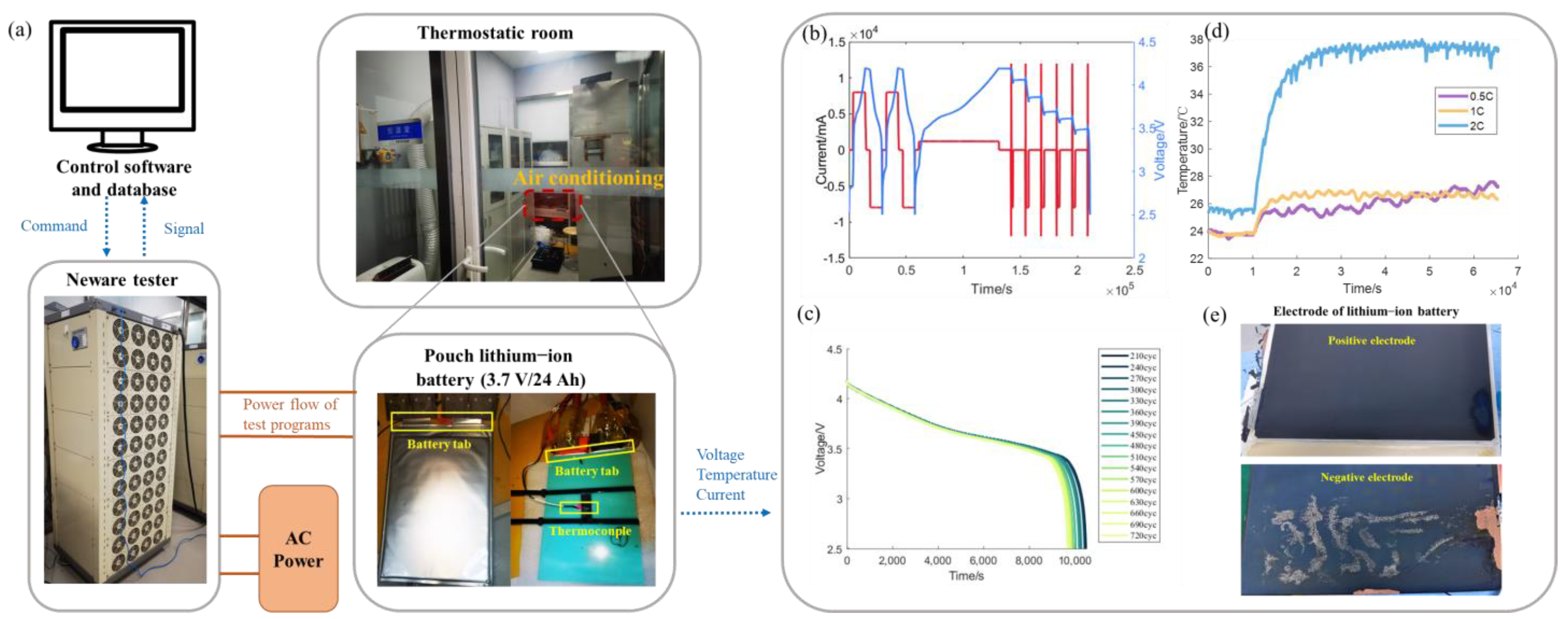
Figure 1. Experiment matrix design of three factors: different battery cycle SOC ranges, DOD ranges, and C-rates. The position of the rectangles represents the SOC range and deeper color indicates larger DOD.
Batteries 08 00188 g001
Figure 2. Experimental setup: (a) test bench for degradation programs and data acquisition; (b) battery capacity test and HPPC test during one cycle; (c) the typical discharging voltage curve evolution with cycle numbers; (d) the temperature change during cycling programs of different C-rates; (e) positive and negative electrode surfaces of one aged battery.
Batteries 08 00188 g002
Figure 3. Daily travel plan of electric vehicle.
Batteries 08 00188 g003
Figure 4. Nominal capacity degradation with equivalent cycle numbers of varied SOC and DOD ranges: (a) 5% DOD, (b) 10% DOD, (c) 20% DOD.
Batteries 08 00188 g004
Figure 5. The loss of the rated capacity of the 15 partitioned SOC intervals at 660 equivalent full cycles, where the average SOC ranges are 10, 30, 50, 70, and 90%, and the DOD ranges are 5%, 10%, and 20%, respectively. The bars in red color represent the calendar aging corresponding to the average SOC point measured by the shelf life experiment.
Batteries 08 00188 g005
Figure 6. Deformation curve during the charging and discharging process: (a) deformation value during battery charging and discharging; (b) differentiation of the deformation curve during battery charging and discharging.
Batteries 08 00188 g006
Figure 7. Nominal capacity degradation with equivalent cycle numbers under different DOD and C-rate with the same average SOC of 50%; (a) 40%DOD, (b) 80%DOD.
Batteries 08 00188 g007
Figure 8. Nominal capacity degradation with equivalent cycle numbers under different DOD and C-rate with the same average SOC of 50% with varied charging currents: (a) 0.5 C, (b) 1 C, (c) 2 C.
Batteries 08 00188 g008
Figure 9. Incremental capacity (dQ/dV) curves of the six selected working conditions: (ac) 0.5 C, 0−20% SOC, 40−60% SOC, 80−100% SOC; (d) 1 C, 20−80% SOC; (e) 2 C, 40−60% SOC; (f) 2 C, 30−70% SOC.
Batteries 08 00188 g009
Figure 10. Voltage parameter reconstruction (VPR) method and comparison:(a) comparison of results between RF-VPR method and VPR method; (b) voltage curves of the full battery, anode, and cathode half cells; (c) iteration process comparison of the VPR with five parameters and the reduced-freedom VPR (RF-VPR). The vertical coordinate represents the root-mean-square error (RMSE) of the simulation curves against the experimental results.
Batteries 08 00188 g010
Figure 11. Battery aging mechanism indicator evolution of different SOC, DOD, and C-rate: (a) capacity of the positive electrode Cp; (b) capacity of the negative electrode Cn; (c) amount of the total available lithium QLi.
Batteries 08 00188 g011
Figure 12. Cumulative degradation function: (a) refined piecewise linear CDF under 0.5 C; (b) calendar aging induced by difference shelf SOC and time of days.
Batteries 08 00188 g012
Figure 13. V2G and normal charging profiles.
Batteries 08 00188 g013
Figure 14. Capacity degradation versus time with different load profiles after 1.5 years: (a) calendar aging; (b) cyclical aging; (c) total aging.
Batteries 08 00188 g014
Figure 15. Battery degradation comparison after 1.5 years under different EV profiles: (a) absolute value of the SOH decrease; (b) average degradation by cycling (%/1%SOC).
Batteries 08 00188 g015
Table 1. Nominal specifications of the test battery.
Item Specification
Cathode materialLi(NiMnCo)O2
Anode materialGraphite
Electrolyte1 M LiPF6/EC:EMC (3:7)
Nominal capacity24 Ah
Nominal voltage3.7 V
Max. continuous charge current1 C
Charge cut-off voltage4.2 V
Max. continuous discharge current3 C
Discharge cut-off voltage2.5 V
Publisher’s Note: MDPI stays neutral with regard to jurisdictional claims in published maps and institutional affiliations.