Article

Elucidating Spatial Distribution of Electrochemical Reaction in a Porous Electrode by Electrochemical Impedance Spectra for Flow Batteries

Guangdong Provincial Key Laboratory of Fuel Cell Technology, School of Chemistry and Chemical Engineering, South China University of Technology, Guangzhou 510641, China
*
Authors to whom correspondence should be addressed.
Batteries 2023, 9(1), 17; https://doi.org/10.3390/batteries9010017
Submission received: 20 October 2022 / Revised: 22 December 2022 / Accepted: 24 December 2022 / Published: 26 December 2022
(This article belongs to the Special Issue Redox Flow Batteries: Recent Advances and Perspectives)

Abstract

:
A porous electrode is an essential component in a flow battery, and its structure determines the battery’s performance. The coupling of the multi-temporal-spatial-scale processes (e.g., electrochemical reaction, mass transfer, charge transfer) makes the recognition of each process complicated. Herein, a symmetric flow cell device is developed, and the electrochemical impedance measurement (two- or three-electrode configuration) is realized to elucidate the electrochemical processes. First, the effect of flow rate and concentration on the impedance spectra is investigated to identify the electrochemical processes. Second, the distributed resistance is quantified to describe the spatial distribution of the electrochemical reaction. It is found that the electrochemical reaction occurs near the membrane side at a low polarization current, and the reaction zones spatially extend from the membrane side to the current collector with the increase of imposed polarization. Such an evolution of the spatial distribution stems from the trade-off between the mass transfer and the ion conduction in the porous electrode. This work provides an experimental method to nondestructively probe the electrochemical processes, and the result provides guidance for developing innovative electrode structures for flow batteries.

1. Introduction

The utilization of renewable energies, including solar and wind power, is important for achieving sustainable development. However, their unstable and intermittent nature hinders their efficient applications. Therefore, it is urgent to develop safe and affordable large-scale energy storage technologies [1,2,3,4,5,6]. Aqueous redox flow batteries (ARFBs) are acknowledged as one of the most promising candidates for large-scale energy storage due to their attractive characteristics of intrinsic safety, flexible design, and environmental friendliness [7,8,9,10,11]. Despite remarkable progress recently, the demand for high energy density must be satisfied for further widespread application [12,13]. As the core components of flow batteries, porous electrodes provide active sites for electrochemical reactions, pathways for mass transfer, and contiguous electron conduction paths between the membrane and the current collector [12,14]. Electrode optimization is essential to improve the power density of flow batteries. Previous work has been focused on surface modification [15,16,17,18,19] and microstructural arrangements [20,21,22,23], which substantially improved the battery’s performance. However, the coupling complexity of the electrochemical reaction with the mass transfer process poses challenges to the rational design of porous electrodes. Developing in situ diagnostics to elucidate these complicated processes is the prerequisite to addressing this issue.
Electrochemical impedance spectroscopy (EIS) enables the valid identification of various physicochemical processes with different relaxation frequencies. Previously, the EIS has been employed to measure the ohmic resistance [24,25,26] and the charge transfer resistance [15,16,17,18,19] in a flow battery. Neergat applied EIS to investigate the transport of redox species across the electrode-electrolyte interface, and the effect of the electrode composition was clarified [27]. In a pioneer work, Mench applied the macrohomogeneous porous electrode theory and established a model to resolve the EIS spectra, from which the ohmic, charge transfer, and diffusion resistance could be quantified [28]. Unfortunately, it was further found that it is not easy to collect high-quality impedance spectra at an operational flow rate in flow batteries [29]. Therefore, an experimental setup is needed for collecting the EIS to elucidate the electrochemical processes in the porous electrode.
In this work, we develop a symmetric flow cell device with an Ag/AgCl reference electrode, which enables two- or three-electrode impedance measurements. Potassium ferricyanide/potassium ferrocyanide (K3[Fe(CN)6] / K4[Fe(CN)6]) is used as the model redox couple. We first investigate the effect of electrolyte flow rates and concentration on the impedance spectra using the two-electrode configuration to identify the electrochemical processes. Then, the impedance spectra in the range from the open-circuit voltage (OCV) to the limiting current potential, for the first time, are collected using the three-electrode configuration. A model is introduced to describe the relationship between the applied potential and the spatial distribution of electrochemical reactions through the thickness of the porous electrode. The distributed resistance (Rdistributed) is quantitatively derived and used as an effective indicator to describe this distribution. As such, the three-electrode impedance measurement setup developed in this work enables the nondestructive recognition of the electrochemical processes in the porous electrode, which may help guide the electrode design in the flow battery.

2. Materials and Methods

2.1. Materials

All of the reagents were used as received without any further purification. Potassium ferricyanide (K3[Fe(CN)6]) and potassium ferrocyanide (K4[Fe(CN)6]) were of analytical grade purchased from Shanghai Lingfeng Chemical Reagent Co., Ltd., Shanghai, China. Potassium chloride (KCl, 99.5% purity) and ethanol (EtOH, analytical grade) were provided by Sinopharm Chemical Reagent Co., Ltd., Shanghai, China. Deionized (DI) water was obtained from RO DI manufactured by Hitech Instruments CO., Ltd., Shanghai, China.
The carbon felts (CFs) with uncompressed thicknesses of 3, 5, and 8 mm were purchased from Tianjin Carbon Co., Ltd., Tianjin, China, and were cut into 5 cm × 5 cm squares and used as electrodes. To remove residuals and impurities, CFs were treated with DI water and ethanol and eventually dried under vacuum at 80 °C. The Nafion 115 membrane from Dupont was used as the separator. As pretreatment, the membrane was treated in 3–5 wt% H2O2 solution at 80 °C for an hour and then in 0.5 M H2SO4 at 80 °C for another two hours. Finally, it was rinsed in DI water several times before use.
The electrolyte solution was prepared by dissolving equimolar K3[Fe(CN)6] and K4[Fe(CN)6] in 1.0 M KCl solution. The amount of electrolyte was 60 mL in all experiments. For simplicity, the electrolyte solution is designated as x M K3[Fe(CN)6] at 50% state of charge (SOC), where x represents the total concentration of K3[Fe(CN)6] and K4[Fe(CN)6].

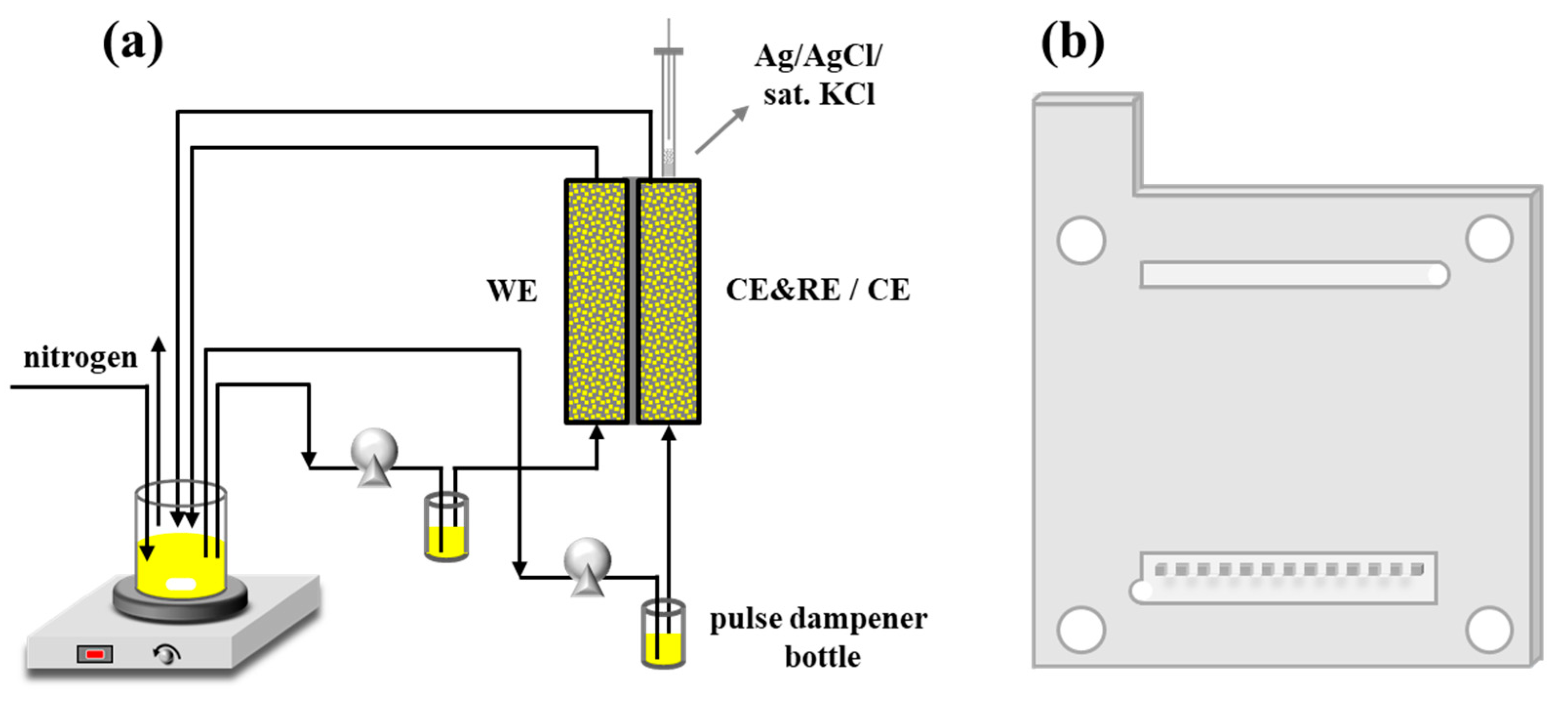
2.2. Experimental Setup

A symmetric flow cell configuration was designed for steady-state diagnostics [28,30], in which the anode and the cathode were fed with the electrolyte (see Figure 1a). The symmetric cell consisted of two CF electrodes, a Nafion 115 membrane, two Teflon gaskets, and two titanium current collectors. The compression ratio of the electrode was fixed at 20% by the Teflon gasket. Therefore, the final thicknesses of the 3, 5, and 8 mm- electrodes were 2.4, 4.0, and 6.4 mm, respectively. Flow channels were carved on the current collectors to realize a uniform inlet velocity at the electrode entrance (Figure 1b) [30]. The electrolyte was circulated through a continuous fluid circuit. In this circuit, a pulse dampener was introduced to relieve fluctuation [29]. To prevent the oxidation of K4[Fe(CN)6], the electrolyte was protected by a continuous humidified nitrogen purge.
Two electrode configurations were employed to fulfill the measurements. As shown in Figure 1a, a two-electrode configuration consists of a left electrode as the working electrode (WE) and a right electrode as both the reference electrode (RE) and the counter electrode (CE). For a three-electrode configuration, the right electrode acts as the CE only, and an Ag/AgCl electrode is inserted as the RE. The electrolyte velocity through the WE is adjusted based on experimental demands, and the velocity at the other side is kept constant (60 mL min−1).

2.3. Electrochemical Measurements

Polarization curves and EIS were recorded by a Zahner Zennium potentiostat with a current range of ±2.5 A at room temperature. In the two-electrode configuration, impedance spectra were collected with an AC amplitude of 5 mV superimposed on open circuit voltage (0 V) by sweeping the frequency from 30 kHz to a lower limit frequency, 20 mHz for 40–80 mL min−1 and 10 mHz for the 30 mL min−1. In the three-electrode configuration, polarization measurements were performed by increasing the potential of every 25 mV in a stepwise manner versus open circuit voltage (0.283 V vs. Ag/AgCl). At the end of each step, the impedance spectrum was collected using an AC amplitude of 5 mV superimposed on the DC polarization potential in a frequency range of 30 kHz–2 Hz for 3 mm- and 5 mm-thick electrodes (the lower limit is 4 Hz for the 8 mm-thick electrode).
The EIS spectra were checked using the linear Kramers–Kronig transforms based on the Lin-KK tool [31]. The transforms’ results (Figures S1 and S2 in the Supplementary Materials) fully verified that the spectra were valid. Finally, the data were fitted using complex non-linear regression least-squares (CNRLS) fitting algorithm with Zahner Analysis software. A typical fitting result is given in Table S1.

3. Results and Discussion

3.1. Full Cell Impedance at Open Circuit Voltage

The impedance spectra of a full cell using the two-electrode configuration were analyzed systematically. Figure 2 presents full cell impedance spectra recorded at various electrolyte velocities. As shown in Figure 2a, the connection of L, Rseries, and four (RQ) in series is utilized as the equivalent circuit model to fit the EIS patterns. Therein, L is the lead inductance, and Rseries represents series resistance mainly related to the ionic conductivity of the electrolyte and the membrane. The (RdistributedQdistributed) is used to depict the distributed impedance of the porous electrodes [32,33], where Rdistributed and Qdistributed represent the distributed resistance and the distributed capacitance, respectively. The distributed impedance originates from two types of current conduction in parallel, i.e., electron-conducting in carbon fibers and ion-conducting in pores [29,34,35]. It is acknowledged that the conductivity of carbon fibers is much higher than that of the electrolyte; therefore, the electronic resistance is negligible, and the ion-conducting resistance predominates in the distributed resistance. The (RctQdl) is attributed to the electron transfer process through the electrode–electrolyte interface. Due to the decent charge transfer kinetics of K3[Fe(CN)6] / K4[Fe(CN)6], the (RdistributedQdistributed) and the (RctQdl) present one arc in the Nyquist plot (Figure 2b) at high-frequency range (30 kHz–100 Hz) [29], which corresponds to only one phase peak in the bode plot (Figure 2c). The middle frequency arc (100–2 Hz) shown in Figure 2b is generally attributed to the mass transport [36], which is represented as the (RconvectiveQconvective). Figure 2d indicates that (RconvectiveQconvective) is velocity-dependent, and its characteristic frequency increases with the velocity, which is attributed to the convective mass transfer in pores. In the low-frequency range (<2 Hz), the characteristic semi-infinite transport is substituted by a finite transport under the hydrodynamic conditions, fitted using the (RdiffusionQdiffusion) [27]. The low-frequency phase peak in Figure 2c shows the characteristic frequency yields a positive shift with increasing flow rates, indicating that the finite diffusion layer thickness near the carbon fiber surface decreases in this process [28,29,37] and, thus, strengthens the diffusion process. The impedance is extracted and plotted versus velocity in Figure 2e. It is seen that at the concentration of 0.050 M, the diffusion resistance is the main contributor to the total impedance, which gradually decreases as the velocity increases.
Figure 3 presents the effect of the concentration on the impedance. First, the increase in the concentration yields a slight decrease in the Rseries, due to the increase in the ionic conductance. Second, the middle frequency arc gets weakened with an increase in concentration (Figure 3a–c), consistent with the change in velocity, as seen in Figure 2d. As shown in Figure 3b–d, the rise of concentration does not shift the characteristic frequency of (RdiffusionQdiffusion), which yields a substantial decrease in Rdiffusion.

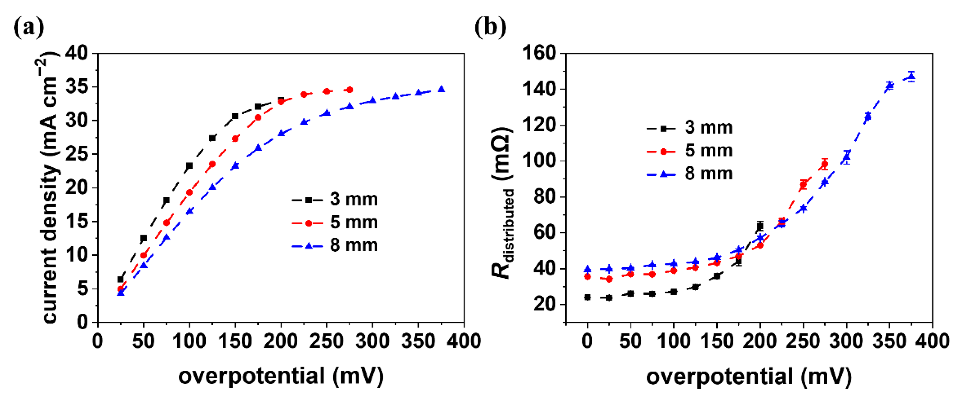
3.2. Impedance under Different Polarization

Polarization potential was then applied by the three-electrode configuration, and the EIS was collected to investigate the coupling effect of the electrochemical reaction on the mass transfer. For simplicity, a model is presented to depict the spatial distribution of electrochemical reactions through the thickness of the porous electrode. The porous electrode is a collection of parallel pores between the current collector and the membrane [38], as seen in Figure 4a. The electron is transferred through the carbon fiber from/off the polar plate and the ion through the pore from/off the membrane side. It is acknowledged that the former process proceeds much faster than the latter one. Therefore, the electrochemical reaction occurs near the membrane side at low polarization currents [13,39], as shown in Figure 4b, under which conditions the consumption of the electroactive species can be sufficiently compensated by the mass transfer. As the polarization current increases, the competing mass transfer of the electroactive species and ions yields a spatial distribution in the pores. As a result, both the current and potential spatially extend from the membrane side to the current collector.
The impedance spectra of the 5 mm electrode were collected in the frequency range of 30 kHz–2 Hz at different potentials. The spectra at a lower frequency (<2 Hz), in which range the element (RdiffusionQdiffusion) resides, were not collected due to the distortion of the curve. Figure 5a,b reveal that the impedance spectra closely depend on the applied overpotential. Figure 5c shows the resistance values derived from the data fitting. First, Rct is the lowest resistance and remains constant in the investigated potential window, indicating that the charge transfer proceeds sufficiently fast at the interface. Second, Rseries also remains constant as it is mainly contributed by the supporting electrolyte. Third, both Rdistributed and Rconvective yield a mild increase at overpotentials < 200 mV and then drastically increase with the applied potential. At low overpotentials, the electrochemical reaction occurs near the membrane side. The short ion conduction distance and sufficient mass transfer in pores correspond to the small values of Rdistributed and Rconvective. Then, the current increases with the potential, which reaches a plateau at ca. 200 mV. The presence of the limiting current indicates that both the mass transfer and ion conduction are spatially extended in deep pores (near the current collector), which correspond to the large values of Rdistributed and Rconvective. It is proposed that the Rdistributed can be used as an indicator to depict the spatial distribution of the electrochemical reaction through the thickness of the porous electrode.
The electrode thickness is a facile parameter to tune the battery’s performance. Its effect on the Rdistributed was, thus, investigated for further optimizing the electrode. Two other thicknesses, viz. 3 and 8 mm, were investigated, and the EIS is displayed in Figures S4 and S5. The polarization curves and the Rdistributed-overpotential plots are shown in Figure 6. First, it is seen that the current increases with the overpotential and finally achieves a limiting one. Notably, the limiting current is similar for the three electrodes, understandable as the battery is fed with an identical flux. Second, the current decreases as the thickness increases at the same overpotential. The reason is that a thinner electrode yields a larger velocity for a given flux, thereby enhancing the mass transfer in the porous electrode. In line with this understanding, the Rdistributed increases with the thickness at lower overpotentials, as shown in Figure 6b. In addition, the Rdistributed yields a drastic increase at higher overpotentials, which can be explained by the extended distribution of the reaction along the pores. The above findings indicate that structural optimization is crucial for the battery’s performance.

4. Conclusions

An electrochemical impedance test device consisting of a symmetric flow cell with an Ag/AgCl reference electrode was designed to elucidate the complicated electrochemical processes within the porous electrode. The full cell impedance spectra collected with the two-electrode configuration exhibited three arcs, well described with an equivalent circuit model, namely LRseries(RdistributedQdistributed) (RctQdl) (RconvectiveQconvective) (RdiffusionQdiffusion). The impedance spectra under various polarizations were, for the first time, collected using the three-electrode configuration. Quantitative analysis suggested that the distribution resistance could effectively describe the spatial distribution of the electrochemical reactions in the direction of electrode thickness, which could help optimize the porous electrode in the flow battery.

Supplementary Materials

The following are available online at https://www.mdpi.com/article/10.3390/batteries9010017/s1, Figure S1: A typical linear Kramers-Kronig transform result in the two-electrode configuration, Figure S2: Typical linear Kramers-Kronig transform results in the three-electrode configuration, Figure S3: Effect of anodic polarization on the electrochemical impedance and the current density with an assembled cell using 5 mm-thick electrodes, Figure S4: Effect of anodic polarization on the electrochemical impedance and the current density with an assembled cell using 3 mm-thick electrodes, Figure S5: Effect of anodic polarization on the electrochemical impedance and the current density with an assembled cell using 8 mm-thick electrodes, Table S1: Fitting results of flow battery impedance using the two-electrode configuration at 80 mL min−1 with 0.050 M K3[Fe(CN)6] at 50% SOC.

Author Contributions

Conceptualization, J.Z. and Z.L; methodology, Q.G. and Z.X; validation, Q.G., X.Y. and Z.X.; investigation, J.Z.; data curation, Q.G., X.Y. and Z.X.; writing—original draft preparation, J.Z. and Q.G.; writing—review and editing, Z.F. and Z.L.; supervision, J.Z., Z.F. and Z.L. All authors have read and agreed to the published version of the manuscript.

Funding

This research was funded by the National Natural Science Foundation of China (Nos. U22A20417, 21975081, 22178126, 22108085), the Science and Technology Program of Guangzhou (2022B03J00668), and the Guangdong Basic and Applied Basic Research Foundation (No. 2020A1515010378).

Institutional Review Board Statement

Not applicable.

Informed Consent Statement

Not applicable.

Data Availability Statement

Not applicable.

Conflicts of Interest

The authors declare no conflict of interest.

References

  1. Xu, Y.; Xie, C.X.; Li, T.Y.; Li, X.F. A High Energy Density Bromine-Based Flow Battery with Two-Electron Transfer. ACS Energy Lett. 2022, 7, 1034–1039. [Google Scholar] [CrossRef]
  2. Zhang, H.; Sun, C.Y.; Ge, M.M. Review of the Research Status of Cost-Effective Zinc–Iron Redox Flow Batteries. Batteries 2022, 8, 202. [Google Scholar] [CrossRef]
  3. Whitehead, A.H.; Robertson, A.; Martin, B.; Martin, E.; Wilson, E. Experimental Benchmarking of Redox Flow Cells. Batteries 2022, 8, 207. [Google Scholar] [CrossRef]
  4. Wu, W.D.; Luo, J.; Wang, F.; Yuan, B.; Liu, T.L. A Self-Trapping, Bipolar Viologen Bromide Electrolyte for Redox Flow Batteries. ACS Energy Lett. 2021, 6, 2891–2897. [Google Scholar] [CrossRef]
  5. Ai, F.; Wang, Z.Y.; Lai, N.C.; Zou, Q.L.; Liang, Z.; Lu, Y.C. Heteropoly Acid Negolytes for High-Power-Density Aqueous Redox Flow Batteries at Low Temperatures. Nat. Energy 2022, 7, 417–426. [Google Scholar] [CrossRef]
  6. Sun, C.; Zhang, H. Review of the Development of First-Generation Redox Flow Batteries: Iron-Chromium System. ChemSusChem 2022, 15, e202101798. [Google Scholar] [CrossRef] [PubMed]
  7. Amini, K.; Gostick, J.; Pritzker, M.D. Metal and Metal Oxide Electrocatalysts for Redox Flow Batteries. Adv. Funct. Mater. 2020, 30, 1910564. [Google Scholar] [CrossRef]
  8. Esan, O.C.; Shi, X.Y.; Pan, Z.F.; Huo, X.Y.; An, L.; Zhao, T.S. Modeling and Simulation of Flow Batteries. Adv. Energy Mater. 2020, 10, 2000758. [Google Scholar] [CrossRef]
  9. Gao, J.X.; Amini, K.; George, T.Y.; Jing, Y.; Tsukamoto, T.; Xi, D.W.; Gordon, R.G.; Aziz, M.J. A High Potential, Low Capacity Fade Rate Iron Complex Posolyte for Aqueous Organic Flow Batteries. Adv. Energy Mater. 2022, 12, 2202444. [Google Scholar] [CrossRef]
  10. Huang, S.Q.; Zhang, H.; Salla, M.; Zhuang, J.H.; Zhi, Y.F.; Wang, X.; Wang, Q. Molecular Engineering of Dihydroxyanthraquinone-Based Electrolytes for High-Capacity Aqueous Organic Redox Flow Batteries. Nat. Commun. 2022, 13, 4746. [Google Scholar] [CrossRef]
  11. Chen, Q.R.; Lv, Y.G.; Yuan, Z.Z.; Li, X.F.; Yu, G.H.; Yang, Z.J.; Xu, T.W. Organic Electrolytes for pH-Neutral Aqueous Organic Redox Flow Batteries. Adv. Funct. Mater. 2021, 32, 2108777. [Google Scholar] [CrossRef]
  12. Wang, R.; Li, Y.S. Carbon Electrodes Improving Electrochemical Activity and Enhancing Mass and Charge Transports in Aqueous Flow Battery: Status and Perspective. Energy Storage Mater. 2020, 31, 230–251. [Google Scholar] [CrossRef]
  13. Zhou, X.L.; Zhao, T.S.; An, L.; Zeng, Y.K.; Yan, X.H. A Vanadium Redox Flow Battery Model Incorporating the Effect of Ion Concentrations on Ion Mobility. Appl. Energy 2015, 158, 157–166. [Google Scholar] [CrossRef]
  14. Forner-Cuenca, A.; Brushett, F.R. Engineering Porous Electrodes for Next-Generation Redox Flow Batteries: Recent Progress and Opportunities. Curr. Opin. Electrochem. 2019, 18, 113–122. [Google Scholar] [CrossRef]
  15. Wang, R.; Li, Y.S.; Liu, H.Y.; He, Y.L.; Hao, M.S. Sandwich-Like Multi-Scale Hierarchical Porous Carbon with a Highly Hydroxylated Surface for Flow Batteries. J. Mater. Chem. A 2021, 9, 2345–2356. [Google Scholar] [CrossRef]
  16. Zhang, X.Y.; Ye, X.L.; Huang, S.P.; Zhou, X.L. Promoting Pore-Level Mass Transport/Reaction in Flow Batteries: Bi Nanodot/Vertically Standing Carbon Nanosheet Composites on Carbon Fibers. ACS Appl. Mater. Interfaces 2021, 13, 37111–37122. [Google Scholar] [CrossRef]
  17. Wang, R.; Li, Y.S.; Wang, Y.N.; Fang, Z. Phosphorus-Doped Graphite Felt Allowing Stabilized Electrochemical Interface and Hierarchical Pore Structure for Redox Flow Battery. Appl. Energy 2020, 261, 114369. [Google Scholar] [CrossRef]
  18. Xu, Z.Y.; Zhu, M.D.; Zhang, K.Y.; Zhang, X.H.; Xu, L.X.; Liu, J.G.; Liu, T.; Yan, C.A.W. Inspired by “Quenching-Cracking” Strategy: Structure-Based Design of Sulfur-Doped Graphite Felts for Ultrahigh-Rate Vanadium Redox Flow Batteries. Energy Stor. Mater. 2021, 39, 166–175. [Google Scholar] [CrossRef]
  19. Jin, C.X.; Lei, H.Y.; Liu, M.Y.; Tan, A.D.; Piao, J.H.; Fu, Z.Y.; Liang, Z.X.; Wang, H.H. Low-Dimensional Nitrogen-Doped Carbon for Br2/Br Redox Reaction in Zinc-Bromine Flow Battery. Chem. Eng. J. 2020, 380, 122606. [Google Scholar] [CrossRef]
  20. Wan, S.B.; Liang, X.W.; Jiang, H.R.; Sun, J.; Djilali, N.; Zhao, T.S. A Coupled Machine Learning and Genetic Algorithm Approach to the Design of Porous Electrodes for Redox Flow Batteries. Appl. Energy 2021, 298, 117177. [Google Scholar] [CrossRef]
  21. Sun, J.; Wu, M.C.; Fan, X.Z.; Wan, Y.H.; Chao, C.Y.H.; Zhao, T.S. Aligned Microfibers Interweaved with Highly Porous Carbon Nanofibers: A Novel Electrode for High-Power Vanadium Redox Flow Batteries. Energy Storage Mater. 2021, 43, 30–41. [Google Scholar] [CrossRef]
  22. Wan, C.T.; Jacquemond, R.R.; Chiang, Y.M.; Nijmeijer, K.; Brushett, F.R.; Forner-Cuenca, A. Non-Solvent Induced Phase Separation Enables Designer Redox Flow Battery Electrodes. Adv. Mater. 2021, 33, e2006716. [Google Scholar] [CrossRef] [PubMed]
  23. Wang, R.; Li, Y.S.; He, Y.L. Achieving Gradient-Pore-Oriented Graphite Felt for Vanadium Redox Flow Batteries: Meeting Improved Electrochemical Activity and Enhanced Mass Transport from Nano-to Micro-Scale. J. Mater. Chem. A 2019, 7, 10962–10970. [Google Scholar] [CrossRef]
  24. Jin, S.J.; Fell, E.M.; Vina-Lopez, L.; Jing, Y.; Michalak, P.W.; Gordon, R.G.; Aziz, M.J. Near Neutral pH Redox Flow Battery with Low Permeability and Long-Lifetime Phosphonated Viologen Active Species. Adv. Energy Mater. 2020, 10, 2000100. [Google Scholar] [CrossRef]
  25. Liu, L.; Yao, Y.X.; Wang, Z.Y.; Lu, Y.C. Viologen Radical Stabilization by Molecular Spectators for Aqueous Organic Redox Flow Batteries. Nano Energy 2021, 84, 105897. [Google Scholar] [CrossRef]
  26. Luo, J.; Hu, B.; Debruler, C.; Bi, Y.J.; Zhao, Y.; Yuan, B.; Hu, M.W.; Wu, W.D.; Liu, T.L. Unprecedented Capacity and Stability of Ammonium Ferrocyanide Catholyte in pH Neutral Aqueous Redox Flow Batteries. Joule 2019, 3, 149–163. [Google Scholar] [CrossRef] [Green Version]
  27. Leuaa, P.; Priyadarshani, D.; Tripathi, A.K.; Neergat, M. Internal and External Transport of Redox Species across the Porous Thin-Film Electrode/Electrolyte Interface. J. Phys. Chem. C 2019, 123, 21440–21447. [Google Scholar] [CrossRef]
  28. Sun, C.N.; Delnick, F.M.; Aaron, D.S.; Papandrew, A.B.; Mench, M.M.; Zawodzinski, T.A. Resolving Losses at the Negative Electrode in All-Vanadium Redox Flow Batteries Using Electrochemical Impedance Spectroscopy. J. Electrochem. Soc. 2014, 161, A981–A988. [Google Scholar] [CrossRef]
  29. Pezeshki, A.M.; Sacci, R.L.; Delnick, F.M.; Aaron, D.S.; Mench, M.M. Elucidating Effects of Cell Architecture, Electrode Material, and Solution Composition on Overpotentials in Redox Flow Batteries. Electrochim. Acta 2017, 229, 261–270. [Google Scholar] [CrossRef] [Green Version]
  30. You, X.; Ye, Q.; Cheng, P. The Dependence of Mass Transfer Coefficient on the Electrolyte Velocity in Carbon Felt Electrodes: Determination and Validation. J. Electrochem. Soc. 2017, 164, E3386–E3394. [Google Scholar] [CrossRef]
  31. Schönleber, M.; Klotz, D.; Ivers-Tiffée, E. A Method for Improving the Robustness of Linear Kramers-Kronig Validity Tests. Electrochim. Acta 2014, 131, 20–27. [Google Scholar] [CrossRef]
  32. Joy, M.E.; Tripathi, A.K.; Priyadarshani, D.; Choudhury, D.; Neergat, M. What Contributes to the Internal Mass-Transport Resistance of Redox Species through Porous Thin-Film Electrodes? Phys. Chem. Chem. Phys. 2022, 24, 3886–3895. [Google Scholar] [CrossRef] [PubMed]
  33. Hitz, C.; Lasia, A. Experimental Study and Modeling of Impedance of the HER on Porous Ni Electrodes. J. Electroanal. Chem. 2001, 500, 213–222. [Google Scholar] [CrossRef]
  34. Kotz, R.; Carlen, M. Principles and Applications of Electrochemical Capacitors. Electrochim. Acta 2000, 45, 2483–2498. [Google Scholar] [CrossRef]
  35. Lasia, A. Electrochemical Impedance Spectroscopy and Its Applications; Springer: New York, NY, USA, 2014. [Google Scholar]
  36. Schneider, J.; Tichter, T.; Khadke, P.; Zeis, R.; Roth, C. Deconvolution of Electrochemical Impedance Data for the Monitoring of Electrode Degradation in VRFB. Electrochim. Acta 2020, 336, 115510. [Google Scholar] [CrossRef]
  37. Simon, B.A.; Gayon-Lombardo, A.; Pino-Muñoz, C.A.; Wood, C.E.; Tenny, K.M.; Greco, K.V.; Cooper, S.J.; Forner-Cuenca, A.; Brushett, F.R.; Kucernak, A.R.; et al. Combining Electrochemical and Imaging Analyses to Understand the Effect of Electrode Microstructure and Electrolyte Properties on Redox Flow Batteries. Appl. Energy 2022, 306, 117678. [Google Scholar] [CrossRef]
  38. Song, H.K.; Jung, Y.H.; Lee, K.H.; Dao, L.H. Electrochemical Impedance Spectroscopy of Porous Electrodes the Effect of Pore Size Distribution. Electrochim. Acta 1999, 44, 3513–3519. [Google Scholar] [CrossRef]
  39. Huang, S.P.; Lu, Y.J. Numerical Parametric Investigation of Nonaqueous Vanadium Redox Flow Batteries. Batteries 2022, 8, 75. [Google Scholar] [CrossRef]
Figure 1. (a) Schematic of a symmetric cell setup; (b) Schematic of a titanium current collector with flow channels.
Batteries 09 00017 g001
Figure 2. Full cell impedance recorded at OCV at various flow rates. (a) Equivalent circuit model of the impedance spectra; (b) Nyquist plots; (c) Bode plots; (d) Bode phase plots in 100–1 Hz; (e) Resistance value derived from the data fitting. The cell was assembled using 5 mm electrodes. The electrolyte concentration was 0.050 M K3[Fe(CN)6] at 50% SOC. The symbols and the solid lines in Nyquist and Bode plots show the experimental and the fitted data, respectively.
Batteries 09 00017 g002
Figure 3. Effect of electrolyte concentrations on full cell impedance. (a) Nyquist plots; (b) Bode plots; (c) Bode phase plots in 100 Hz–1 Hz; (d) Resistance value derived from the data fitting. The cell was assembled using 5 mm electrodes. The impedance spectra were recorded at OCV at a constant electrolyte velocity of 60 mL min−1. The symbols and the solid lines in Nyquist and Bode plots show the experimental and the fitted data, respectively.
Batteries 09 00017 g003
Figure 4. (a) Structural illustration of the porous electrode and schematic representation of electrochemical reaction that occurred at the interface in one pore; (b) Schematic illustration of the evolution of main electrochemical reaction zone with increasing overpotential in one pore.
Batteries 09 00017 g004
Figure 5. Effect of anodic polarization on the impedance and the current density. (a) Nyquist plots; (b) Bode plots; (c) Resistance value derived from the data fitting; (d) Polarization curve. The cell was assembled using 5 mm-thick electrodes. The electrolyte concentration was 0.050 M K3[Fe(CN)6] at 50% SOC. The measurements were performed at a flow rate of 20 mL min−1.
Batteries 09 00017 g005
Figure 6. Effect of electrode thickness on the current density and the distributed resistance. (a) Polarization curves; (b) Distributed resistance derived from the data fitting. The electrolyte concentration was 0.050 M K3[Fe(CN)6] at 50% SOC. All measurements were performed at a flow rate of 20 mL min−1 at corresponding anodic polarization.
Batteries 09 00017 g006
Disclaimer/Publisher’s Note: The statements, opinions and data contained in all publications are solely those of the individual author(s) and contributor(s) and not of MDPI and/or the editor(s). MDPI and/or the editor(s) disclaim responsibility for any injury to people or property resulting from any ideas, methods, instructions or products referred to in the content.

