Article

Melt-Spinning Mesophase Pitch-Based Graphite Fibers as Anode Materials for High-Rate Lithium-Ion Batteries

1
Beijing Future Technology Innovation Centre for Electrochemical Energy Storage System Integration, North China University of Technology, Beijing 100144, China
2
Beijing HyperStrong Technology Co., Ltd., Beijing 100089, China
*
Author to whom correspondence should be addressed.
Batteries 2023, 9(11), 550; https://doi.org/10.3390/batteries9110550
Submission received: 14 October 2023 / Revised: 3 November 2023 / Accepted: 6 November 2023 / Published: 10 November 2023
(This article belongs to the Special Issue Advanced Cathode and Anode Materials for Lithium/Sodium-Ion Batteries)

Abstract

:
Lithium-ion batteries have rapidly become the most widely used energy storage devices in mobile electronic equipment, electric vehicles, power grid energy storage devices and other applications. Due to their outstanding stability and high conductivity, carbon materials are among the most preferred anode materials for lithium-ion batteries. In this study, mesophase pitch-based graphite fibers (GFs) were successfully prepared through melt-spinning, thermo-oxidative stabilization, carbonization and graphitization and used as anode materials. The radial fiber structure can lower the activation energy and minimize the distance of the Li+ diffusion, while the highly conductive cross-linked network within the fibers benefits the speed up charge transmission. Thus, the as-synthesized graphite fibers demonstrate superior rate capability and cycle stability. GFs exhibit a capacity retention rate of 97.94% and reversible capacity of 327.8 mA h g−1 after 100 cycles at 0.1 C, which is higher than that of natural graphite anode materials (85.66% and 289.7 mA h g−1, respectively). Moreover, the as-synthesized graphite fibers deliver a capacity retention of 64.7% at a high rate of 5 C, which is considerably higher than that of natural graphite (19.7%).

1. Introduction

The issue of energy scarcity and environmental pollution has become serious with the rapid growth of the development of the global economy. Scientists across the world have begun to focus on the development and application of renewable and clean energy [1,2]. Due to the volatility, intermittency and randomness of renewable energies like solar energy and wind energy, large-scale energy storage technologies are required to achieve the effective conversion and storage of this kind of renewable energy [3]. Lithium-ion batteries are a viable energy storage solution to effectively address the issues because of their high energy density, stable electrochemistry, portability, long cycling life and environmentally friendly nature and have found widespread application in startup power, electric vehicles, portable electronics and energy storage power stations [4,5,6,7]. How to improve the energy density as well as the charging/discharging speed of lithium-ion batteries and reduce battery prices rapidly, has driven continuous research interests in recent years [8,9,10,11].
As the primary component of lithium-ion batteries, the anode materials have a direct impact on the energy density, cycle stability, and rate performance of the battery. Existing research indicates that there are numerous possibilities and research opportunities for anode materials [12]. Materials suitable for use as the anode materials in lithium-ion batteries typically have the following properties including reversible intercalation of abundant lithium-ion, a low redox potential and a low potential variation during lithiation and delithiation, high electrical conductivity, a stable structure that does not react with the electrolyte, low prices and extensive source, etc. [13]. Commercial negative electrode materials are currently classified into two types: carbon-based anode materials and non-carbon-based anode materials. Carbon-based materials, such as graphite, graphene and amorphous carbon, are the most commonly utilized anode materials [14,15]. Among them, graphite materials have dominated commercial lithium-ion batteries due to their stable structure, superior lithiation/delithiation properties, being an abundant resource and being highly cost-effective. However, using graphite as the anode material also has a number of issues, including relatively low theoretical capacity, slow lithium intercalation and dendrite formation during fast charging which may cause security issues [16,17,18,19]. Numerous attempts have been made by researchers to modify graphite materials, for instance, surface treatment [20,21], mildly expanded [22], carbon coated [23], doping [24] and nanocrystallization [25]. However, there are still many problems that prevent most novel technologies from being implemented in commercial lithium-ion batteries [16]. It is essential to develop novel anode materials to meet the future demands for lithium-ion batteries with high energy density, high safety and fast charging/discharging properties. There are several factors, such as solid-state diffusion and electrical conductivity, that limit the rate capability of lithium-ion battery electrode materials. In order to enhance the rate capability of electrode materials, it needs a subtle design at the atomic scale to minimize the rate-determining obstacles [26,27].
Carbon fibers are often fitted with excellent thermal/electrical conductivity, high specific performance, good corrosion resistance and an ultra-high modulus, making them particularly appropriate for the fabrication of some unique specialized components [28]. For the purpose of improving the electrical conductivity of electrodes and decreasing the Li+ spread lengths of lithium-ion batteries, researchers have attempted to employ carbon fiber as the anode material [29]. Compared with the widely used polyacrylonitrile (PAN)-based carbon fibers, mesophase pitch-based carbon fibers have improved their ability to achieve lightweight, high stiffness and high directional heat conductivity. The superior qualities of mesophase pitch-based carbon fibers are mostly derived from the large-sized graphite crystallites and the highly favored orientation along the fiber axis, which are governed by the arrangement of mesophase macromolecules in the pitch fibers [28]. These unique structures are generated during the melt-spinning, thermo-oxidative stabilization, carbonization and graphitization stages [30,31], making mesophase pitch-based graphite fibers very suitable as excellent anode material for lithium-ion batteries. Unlike in graphite where lithium-ions can only access the carbon layers from the side, the pore structure and defects inside the graphite fibers can provide more sites for the intercalation of lithium-ions. Based on the irreplaceable properties of mesophase pitch-based graphite fibers, even though current research is mainly focused on developing silicon- and tin-based materials to replace graphite anodes, it is still significant to investigate the impact of using carbon fibers as anode materials to meet the continuous development of electric vehicles and the demand of lithium-ion batteries with excellent rate capability.
In this work, naphthalene mesophase pitch was used as the raw material to produce mesophase pitch-based graphite fibers through the continuous process of melt-spinning under different take-up velocities, thermo-oxidative stabilization, carbonization and graphitization. The microstructure of the as-synthesized mesophase pitch-based graphite fibers was investigated using an X-ray diffractometer, a polarization microscope and a scanning electron microscope. Then the as-synthesized mesophase pitch-based graphite fibers were used as the active materials in the preparation of anode materials, followed by the assembly of CR2016 coin-type cells using Li foils as the counter electrode. The galvanostatic electrochemical measurements and cycle stability measurements were operated under the current density of 0.1 C (37.2 mA g−1), together with rate capacity measurements under 0.5 C, 1 C, 2 C and 5 C to evaluate the electrochemical properties of as-synthesized mesophase pitch-based graphite fibers as anode materials. It is hoped that this work may create new insights for the design and development of anode materials for high-rate lithium-ion batteries and beyond.

2. Materials and Methods

2.1. Material Synthesis

Naphthalene mesophase pitch (Mitsubishi, Tokyo, Japan) was used as raw material, and its detailed parameters are shown in Table 1. The raw material pitch was placed in a single-hole air-pressure melting tank and melted at about 330 °C. The mesophase pitch fibers with different cross-sectional areas and crystal orientations were obtained by using a spinneret with a cross-section size of 3 mm × 0.1 mm (L × W) and by controlling the take-up velocity (15, 30, 45 and 75 m min−1). Then the mesophase pitch fibers were pre-oxidized at 240 °C, carbonized at 1000 °C and graphitized at 3000 °C to obtain the mesophase pitch-based graphite fibers. The mesophase pitch-based graphite fibers were labeled as GFx, and the subscript x was used to represent different take-up velocities.

2.2. Material Characterizations

The structure of the synthesized mesophase pitch-based graphite fibers was investigated using an X-ray diffractometer (XRD, Philips χ′ PERT MPD PRO, PANalytical B.V., Almelo, The Netherlands) with Cu-Kα radiation. The voltage and current of the test tube are 40 kV and 30 mA, respectively. The scanning step is 0.033°, and the scanning range is 10–90°. The diffraction peak of the (002) planes of graphite was corrected by adding a certain proportion of monocrystalline silicon powder to the sample in order to calibrate the Angle error of the instrument by the standard diffraction peak of monocrystalline silicon. The d-spacing of the (002) plane was calculated using the Bragg Formula (1). The degree of graphitization was calculated using the Mering-Maire Formula (2) according to the Franklin model. The crystallite sizes along the c direction or the crystal stacking height were calculated using the Scherrer Formula (3).
d 002 = λ 2 sin θ
g = A d 002 A B
L c = k λ β cos θ
where d002 is the d-spacing of the (002) plane (nm); λ is the wavelength of X-ray with a value of 0.15406 nm; θ is Bragg Angle (rad); g is the degree of graphitization (%); A is d-spacing of completely ungraphitized carbon with a value of 0.3440 nm; B is d-spacing of an ideal graphite crystal with a value of 0.3354 nm; Lc is the crystallite sizes along the c direction or the crystal stacking height (nm); β is full width at half maximum of diffraction peak (rad); and k is the form factor of the crystal with a value of 0.89.
The optical structure was assessed by polarization microscope (PLM, Carl Zeiss Axio Scope.A1, Carl Zeiss AG, Oberkochen, Germany) with a 12 V/100 W halogen lamp as the optical source.
The morphological property was assessed using a scanning electron microscope (SEM, VEGE 3 SBH-EasyProbe, TESCAN, Brno, Czech Republic) with an operating voltage of 30 kV.

2.3. Battery Preparation

Figure 1 shows the preparation procedure of graphite fibers anode materials and the half-cell used for electrochemical performance testing. The as-synthesized mesophase pitch-based graphite fibers were ground into powder using a grinder and then sifted through 400 mesh to be used as the active materials. The homogeneous slurry was prepared by mixing the active materials, Super-P and polyvinylidene fluoride (PVDF) binder (85:5:10 in a mass ratio) in N-methylpyrrolidone (NMP) solution first, and the formed slurry was coated onto copper foil with a thickness of 10 μm to be used as the working electrodes. The CR2016 coin-type cells were manufactured in a glovebox with working electrodes, a counter electrode (Li foils, 12 mm in diameter), a Celgard2325 polypropylene porous membrane and electrolyte of 1 M LiPF6 in ethylene carbonate/dimethyl carbonate/ethyl methyl carbonate (1:1:1 in a volume ratio).
As a contrast sample, spherical natural graphite (NG) with a diameter of 15 μm was employed as the anode material to assemble the CR2016 coin-type cell as described above.

2.4. Electrochemical Tests

The galvanostatic electrochemical measurements and rate capacity measurements were operated on a Neware battery tester with a potential range of 0.005~2.000 V (vs. Li+/Li) and a current density of 0.1 C (37.2 mA g−1), 0.5 C, 1 C, 2 C and 5 C. In this paper, the intercalation of Li+ between carbon layers is represented by the discharge curve and the de-intercalation process of Li+ between carbon layers is represented by the charge curve. The cyclic voltammetry data was obtained at a scanning rate of 0.1 mV s−1 and a potential window from 0.005~2.000 V (vs. Li+/Li) on an electrochemical workstation (CHI660D, Chenhua, Shanghai, China). The EIS measurements were performed on an electrochemical workstation (CHI660D, Chenhua, Shanghai, China) over a frequency range of 100 kHz to 0.01 Hz. The batteries were subjected to five charge/discharge cycles under a constant current prior to EIS testing.

3. Results and Discussion

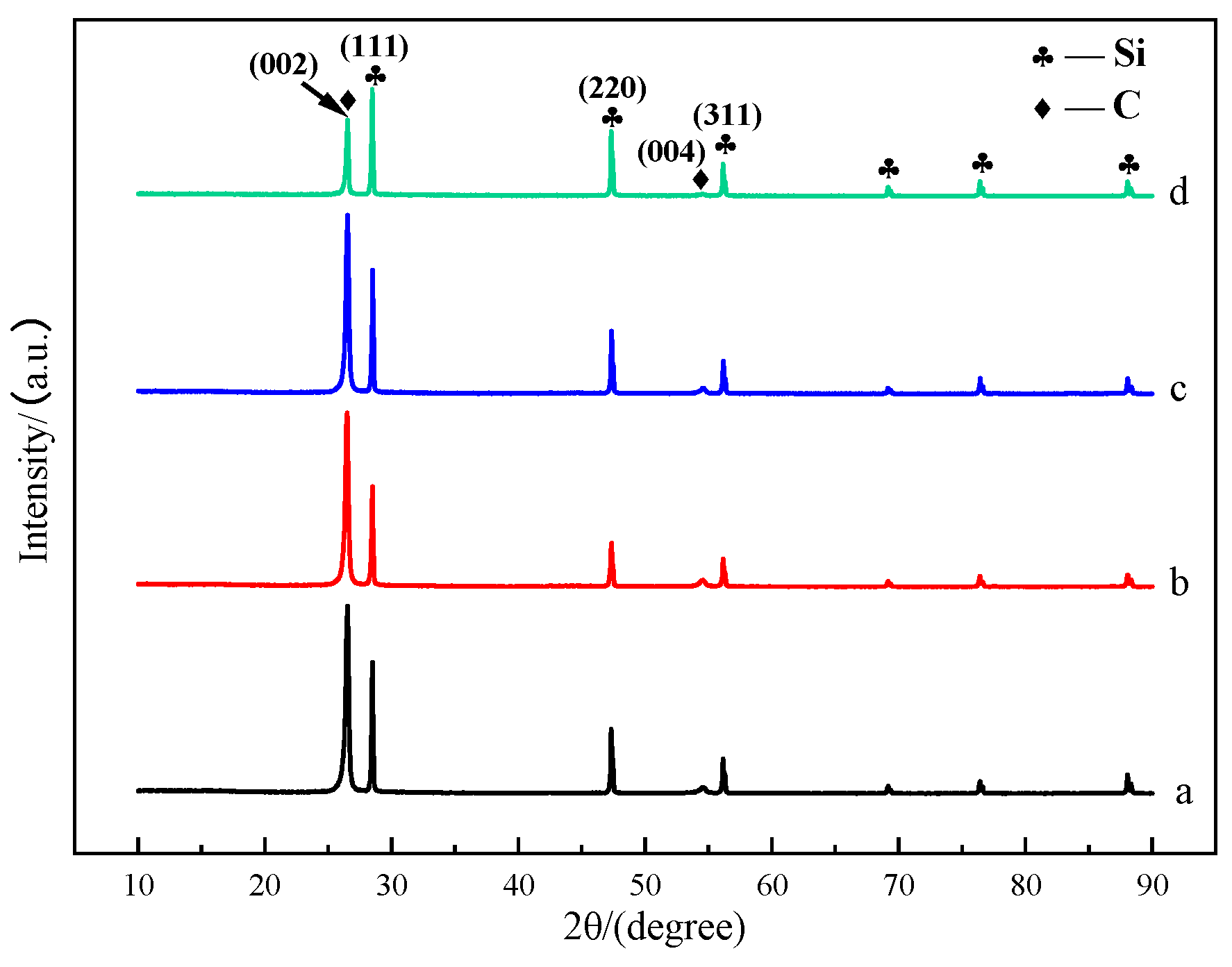
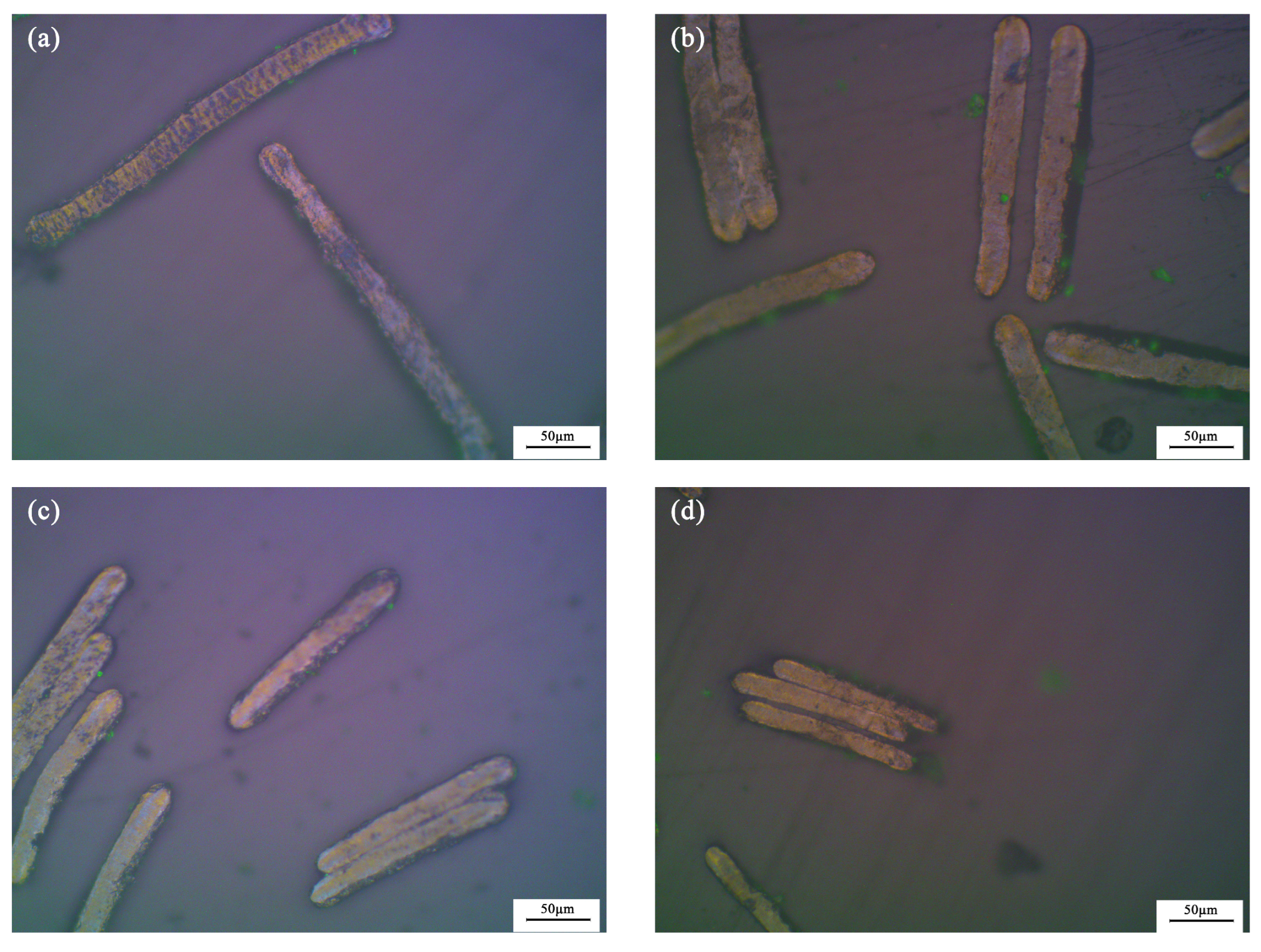
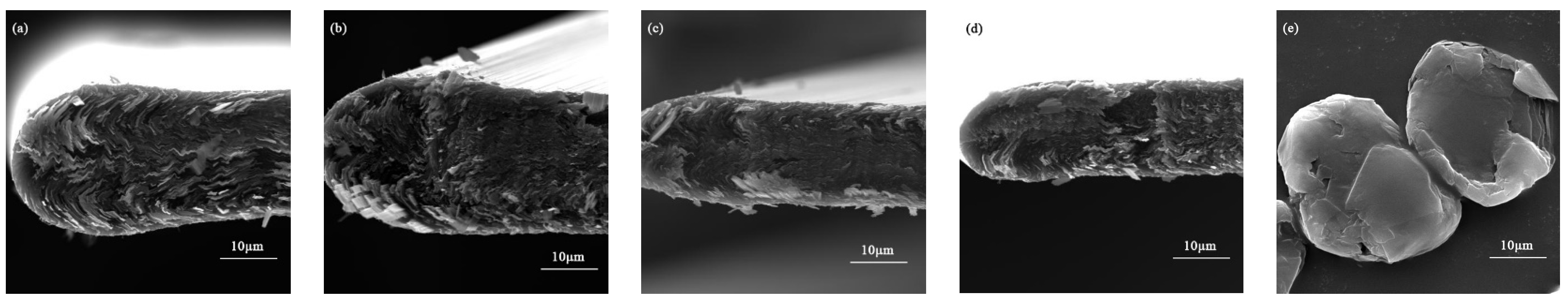
3.1. Morphological and Chemical Characterization

Figure 2 shows the XRD patterns of mesophase pitch-based graphite fibers at different take-up velocities. It can be seen that the locations of the diffraction peaks in the XRD patterns of the mesophase pitch-based graphite fibers at different take-up velocities are basically the same. A strong diffraction peak appears at 2θ = 26.4°, corresponding to the (002) plane of graphite, and a weak diffraction peak appears at 2θ = 54.4°, corresponding to the (004) plane of graphite. The relative intensity of (002) plane diffraction peak decreases gradually with the increase in take-up velocity, which may be attributed to the fact that during the spinning process, the orientation of mesophase liquid crystal changes with the increase in take-up velocity, from being arranged parallel to the main plane of the fiber to being arranged at a certain angle to the main plane of the fiber or partially perpendicular to the main plane. The relative intensity of the diffraction peak decreases most obviously when the take-up velocity is 75 m min−1.
The microcrystalline parameters calculated according to Formulas (1)–(3) of mesophase pitch-based graphite fibers at different take-up velocities are listed in Table 2. The d002 values of the four graphite fibers are close to ideal graphite (d002 = 0.3354 nm). With the increase of take-up velocity, the d-spacing of the (002) plane (d002) gradually increased, and the degree of graphitization (g) and crystallite sizes (Lc) gradually decreased. This may be due to the change in the orientation of the carbon sheet with the increase in the take-up velocity, which restricts the growth of graphite crystals to a certain extent. While the overall orientation of the carbon layers is closely related to the degree of graphitization. As can be seen, the crystallite sizes and orientation of the prepared mesophase pitch-based graphite fibers are significantly influenced by the take-up velocity, and will directly impact the lithium intercalation capacity.
Figure 3 is the PLM images of the as-synthesized mesophase pitch-based graphite fibers at different take-up velocities at 200× magnification. After graphitization at 3000 °C, the surfaces of the graphite fibers have a clear outline and uniform color. The cross-sections of the fibers are generally stratified with a consistent orientation, indicating that the accumulation and orientation of the graphite layers of the as-synthesized mesophase pitch-based graphite fibers are relatively good. The as-synthesized graphite fibers are basically free of curling, creasing and splitting. Naphthalene mesophase pitch used as the raw materials is anisotropic. After the treatment of melt spinning, pre-oxidization, carbonization and graphitization, graphite fibers exhibit a highly consistent orientation. The figure also shows that the thickness and length of the as-synthesized graphite fibers steadily reduce as the take-up velocity increases.
Figure 4 is the SEM images of the as-synthesized mesophase pitch-based graphite fibers at different take-up velocities as well as natural graphite. As shown in Figure 4, it can be seen that the thickness of graphite fibers decreases with the increase in take-up velocity. The cross-section of GF15 is dominated by a wavy layered structure similar to that of graphite sheets. When the take-up velocity increased to 30 m min−1, the cross-sectional texture of the fibers changed significantly. The lamellar structures arranged at a certain angle or approximately perpendicular to the main plane of the fiber appeared near the surface of the fibers. The thickness of layers perpendicular to the main plane of the fibers increases with the increase in the take-up velocity, as shown in Figure 5. However, the carbon layer arrangements of the fibers become somewhat disorderly when the take-up velocity increases to 75 m min−1. The parallel layers parallel to the main side gradually curl into a structure perpendicular to the main side. This change in the orientation of the carbon layer will lead to a decrease in the intensity of the (002) plane in the XRD pattern, which is consistent with the results of XRD analysis. Therefore, it is necessary to choose the appropriate take-up velocity; too low or too high is not conducive to the formation of the required micro morphology. Figure 4e,j shows the morphological structure of natural graphite used for comparison experiments. It can be observed that there are a large number of scaly faults on the surface of spherical particles.

3.2. Electrochemical Characterization

Figure 6a shows the first discharge/charge cycle profiles of as-synthesized mesophase pitch-based graphite fibers at a current density of 37.2 mA h g−1 (0.1 C). Similar to the charge and discharge behavior of the graphite anode material, the voltage drops rapidly to about 0.75 V during the first discharge process as the intercalation of Li+ increases. A voltage platform appears at about 0.7 V, which is a typical feature of the formation process of a solid electrolyte interface (SEI) film. Whereafter, a long and gentle voltage platform appears in the voltage range of 0.25–0.005 V, which corresponds to the intercalation of Li+ in the carbon layers. Figure 6b is part of the voltage-specific capacity profile during the first lithium intercalation process, from which one may find five stages for the lithiation of natural graphite electrodes in the voltage range of 0.3–0 V. According to previous work [32,33,34], these stages correspond to five continuous transitions of Li-graphite interlayer compounds (Li-GICs): L i C 72 L i C 36 L i C 27 L i C 18 L i C 12 L i C 6 . However, unlike natural graphite, there is no distinct voltage platform generated by the phase transition between Li-GICs with a different order during the first lithiation process of as-synthesized mesophase pitch-based graphite fibers anode materials. This may be due to the formation of co-existing high-order and low-order Li-GICs in the intercalation of Li+. Combined with the initial charge/discharge-specific capacity and coulomb efficiency of as-synthesized mesophase pitch-based graphite fibers at the different take-up velocities listed in Table 3, it can be seen that GF45 has the highest initial reversible specific capacity and coulomb efficiency, which are 326.5 mA h g−1 and 84% respectively and are close to that of natural graphite. Part of the irreversible capacity during the first charge/discharge cycle contributes to the formation of a SEI film on the surface of the electrode. It can be seen that the discharge-specific capacity during the first cycle of the as-synthesized fibers is lower than that of natural graphite. The prepared graphite fibers cannot achieve a structure of the ideal graphite and the pore-structure and defects may exist inside the graphite fibers. More lithium ions may need to be consumed to form SEI films. On the other hand, the existence of defective structures increases the compatibility of graphite fibers and electrolytes to a certain extent, which may be one of the reasons for the good capacity retention rate of graphite fibers after 100 cycles.
Figure 7 shows the discharge-specific capacity and efficiency of each cycle from the 1st to the 100th cycle. The fluctuation of the specific capacity in the first few cycles is mainly due to the reduction and decomposition of the electrolyte solvent on the electrode surface to form a SEI film. The formation of a uniform and complete SEI film can effectively prevent continued contact between the electrolyte solvent and the electrode. In order to reduce the calculation deviation, the discharge-specific capacity of the 10th cycle and the 100th cycle are selected to calculate the capacity retention rate of as-synthesized anode materials, and the results are shown in Table 3. It can be seen that compared to natural graphite, the as-synthesized mesophase pitch-based graphite fibers anode materials have good cyclic performance, and the capacity attenuation is quite low after 100 galvanostatic charge/discharge cycles. This is primarily due to the degree of organization of carbon fibers increasing after the graphitization at 3000 °C, which favors lowering the activation energy and accelerating the diffusion of Li+. The microcrystals continue to grow and erase the inter-crystal flaws during the high-temperature treatment process to reduce the co-intercalation of solvated molecules and assist in the formation of SEI film on the electrode surface to improve the compatibility of the electrode and the electrolyte. Therefore, the as-synthesized mesophase pitch-based graphite fiber anode materials have good cycle stability. It can be shown that GF45 has the highest capacity retention rate and reversible cycle capacity among the group, 97.94% and 327.8 mA h g−1, respectively, which is consistent with the outcomes of the first charge/discharge cycle under the galvanostatic mode. In addition to the morphological characterization of the as-synthesized mesophase pitch-based graphite fibers, GF45 demonstrates numerous perpendicular carbon layer structures in relation to the main plane. This kind of arrangement can provide additional intercalation channels for Li+ and reduce the intercalation/deintercalation distance between carbon layers to allow for faster Li+ diffusion. It is also observed from the figure that in the early stage of the cycle test, the discharge-specific capacity underdoes a rising process. This may be partly attributed to the gradual infiltration of the active material by the electrolyte. For the graphite fibers, the folded carbon layer structure results in some of the active substances not being fully utilized in the early stages. As the cycle progresses, the graphite fibers expand with the intercalation of lithium-ions and the intercalation channels are gradually opened, allowing these active substances to participate in the intercalation/deintercalation process, and thus the discharge-specific capacity increases slightly with the increase in the number of cycles.
Furthermore, the as-synthesized mesophase pitch-based graphite fibers show excellent rate capabilities when compared with untreated natural graphite as shown in Figure 8. Spherical natural graphite with a diameter of 15 μm is used as the contrast sample. In order to reduce the calculation deviation, 20 charge/discharge cycles were carried out respectively under different current densities (0.1 C, 0.5 C, 1 C, 2 C, 5 C), and the discharge-specific capacity of the 10–20th cycles were selected as the evaluation basis. The as-synthesized graphite fibers GF45 deliver a reversible discharge-specific capacity of approximately 211 mA h g−1 with a capacity retention of 64.7% at 5 C (current density: 1860 mA g−1), which is considerably higher than that of untreated natural graphite. Furthermore, the disparity in their respective discharge-specific capacities rises as the current density rises. Obviously, in contrast to natural graphite, the as-synthesized graphite fibers have substantially superior cycle stability at higher rates. The degree of graphitization of the as-synthesized graphite fiber increases after high-temperature graphitization treatment, which aids in lowering the activation energy of the Li+ diffusion reaction and promoting the diffusion of Li+. In comparison to natural graphite, the lamellar structure perpendicular to the main layer in the fiber provides more intercalated sites for Li+ while significantly minimizing the distance for diffusion of Li+. The cross-linked network within the graphite fiber also contributes to enhancing the electrical conductivity which can be tightly coupled with super-P to build a good conductive network to boost electron transit speed. Furthermore, the microporous structure of graphite fiber also plays a key role in the storage and diffusion of Li+. Most of the time, the end face, or diamond position, is where the reaction of Li+ intercalated in carbon layers to generate Li-GICs is carried out. Therefore, the radial structure of graphite fiber is very conducive to the rapid diffusion of Li+. Compared with graphite, the Li+ diffusion coefficient of mesophase pitch-based graphite fiber is one order of magnitude higher. Li+ can also be intercalated from the carbon layer if it has structural flaws like micropores. Consequently, the as-synthesized mesophase pitch-based graphite fiber outperforms natural graphite in terms of rate performance and can be used as the anode material for lithium-ion batteries, applying to factors such as frequency regulation energy storage at power stations, startup power, electric vehicles, and unmanned aerial vehicle, etc.
Cyclic voltammetry tests on GF45 were carried out in order to learn more about the electrochemical characteristics of the as-synthesized mesophase pitch-based graphite fibers, and the results are displayed in Figure 9. During the initial reduction process, the peaks in about 0.7 V are consistent with the formation process of SEI film on the electrode surface due to the reduction and decomposition of the solvent molecules in the electrolytes. During the second cycle, the reduction peak basically disappeared, indicating that the SEI film had formed during the initial cycle. Several small reduction peaks below 0.2 V during the second cycle correspond to lithiation reactions of Li+ inserting into the carbon layers to form Li-GICs. In the initial thermo-oxidative stabilization process, a distinct oxidation peak appears at approximately 0.25 V, which corresponds to a highly concentrated delithiation process of as-synthesized graphite fiber. The narrow oxidation peak with high current intensity is in accordance with the long and slow voltage platform in Figure 4, which is advantageous for the output of a stable voltage and in enhancing the battery’s working voltage. There is little variation in the potential difference between the oxidation peak and the reduction peak, implying that the polarization impact is minor when as-synthesized graphite fibers are used as the anode electrode material, and there is a relatively high degree of reversibility in the reaction of lithiation and delithiation.
The electrochemical impedance spectra (EIS) of GF45 and GF75 were obtained in order to learn more about the effect of take-up velocity on the electrochemical characteristics of the as-synthesized mesophase pitch-based graphite fibers, and the results are displayed in Figure 10. Since the battery has already undergone five charge/discharge cycles before the EIS test, it can be assumed that a stable SEI film has been formed. From Figure 10, it can be seen that the electrochemical impedance spectrum of the graphite fiber consists of three parts: a semicircle with two parts overlapping in the high-frequency and mid-frequency regions, and a straight line in the low-frequency region, which represents the impedance of the SEI membrane, charge transfer impedance and impedance of lithium-ion diffusion (Warburg impedance), respectively. Warburg impedance is related to the combined effect of lithium-ion diffusion at the interface of the electrode and the electrolyte. With the increase of take-up velocity, the diameter of the semicircle in the high-frequency region does not change much, and the diameter of the semicircle in the mid-frequency region increases, while the slope of the straight line in the low-frequency region is the same. The results show that the take-up velocity has the most effect on the charge transfer process inside the graphite fiber. The charge transfer impedance of GF45 is lower than GF75 and therefore exhibits better electrochemical performance, which is consistent with the previous tests.

4. Conclusions

Using naphthalene mesophase pitch as raw material, mesophase pitch-based graphite fibers with different crystal orientations were prepared through melt-spinning, thermo-oxidative stabilization, carbonization and graphitization by controlling the take-up velocity. The as-synthesized mesophase pitch-based graphite fibers exhibit outstanding cycle stability when used as anode material for lithium-ion batteries. Graphite fibers obtained at a take-up velocity of 45 m min−1 have the highest capacity retention rate of 97.94% and reversible cycle capacity of 327.8 mA h g−1, after 100 charge/discharge cycles. More importantly, the as-synthesized mesophase pitch-based graphite fibers deliver a reversible discharge-specific capacity of approximately 211 mA h g−1 with a capacity retention of 63.6% at 5 C, which is considerably higher than that of natural graphite anode material. The superior rate capability makes the batteries appropriate for scenarios requiring rapid charging and discharging. The remarkable electrochemical performance should be attributed to the radial fiber structure under melt-spinning and graphitization which contributes to lowering the activation energy and significantly minimizing the distance of Li+ diffusion. Furthermore, the cross-linked network within the graphite fiber also benefits the building of a good conductive network to speed up charge transmission and supply abundant Li+ diffusion channels. This work may create new insights for the design and development of anode materials for high-rate lithium-ion batteries and beyond.
In this manuscript, graphite fibers are used exclusively as the active materials of anodes and in future studies, the use of graphite fibers in combination with natural graphite or silicon-based anode materials can also be considered to explore the coupling effect of different materials. In future research, the pore structure design of graphite fibers can also be considered to obtain a larger reversible capacity while maintaining higher mechanical strength, thus further enhancing the rate performance of graphite fiber used as anode materials.

Author Contributions

Conceptualization, Q.W. and J.L.; methodology, Q.W., J.L. and J.Z.; validation, Q.W., J.L. and J.Z.; formal analysis, Q.W.; investigation, Q.W.; resources, Q.W., J.L. and J.Z.; data curation, Q.W. and J.L.; writing—original draft preparation, Q.W.; writing—review and editing, Q.W., J.L. and J.Z.; supervision, J.L.; funding acquisition, J.L. and J.Z. All authors have read and agreed to the published version of the manuscript.

Funding

This research was funded by China Natural Science Foundation, grant number 52277211 and Beijing Future Technology Innovation Centre for Electrochemical Energy Storage System, grant number 20220468125.

Informed Consent Statement

Not applicable.

Data Availability Statement

The data presented in this study are available on request from the corresponding author. The data are not publicly available due to project privacy.

Conflicts of Interest

The authors declare no conflict of interest. The funders had no role in the design of the study; in the collection, analyses, or interpretation of data; in the writing of the manuscript; or in the decision to publish the results.

References

  1. Brockway, P.E.; Owen, A.; Brand-Correa, L.I.; Hardt, L. Estimation of global final-stage energy-return-on-investment for fossil fuels with comparison to renewable energy sources. Nat. Energy 2019, 4, 612–621. [Google Scholar] [CrossRef]
  2. Fan, E.; Li, L.; Wang, Z.; Lin, J.; Huang, Y.; Yao, Y.; Chen, R.; Wu, F. Sustainable recycling technology for Li-ion batteries and beyond: Challenges and future prospects. Chem. Rev. 2020, 120, 7020–7063. [Google Scholar] [CrossRef] [PubMed]
  3. Behabtu, H.A.; Messagie, M.; Coosemans, T.; Berecibar, M.; Anlay Fante, K.; Kebede, A.A.; Mierlo, J.V. A review of energy storage technologies’ application potentials in renewable energy sources grid integration. Sustainability 2020, 12, 10511. [Google Scholar] [CrossRef]
  4. Yin, H.; Han, D.; Yu, X.; Cao, M.; Hou, Z.; Li, C.; Zhu, M.-Q. Recent advances in electrospun metal chalcogenide anodes for lithium-ion and sodium-ion batteries. ACS Appl. Energy Mater. 2023, 6, 1155–1175. [Google Scholar] [CrossRef]
  5. Kim, T.; Song, W.; Son, D.-Y.; Ono, L.K.; Qi, Y. Lithium-ion batteries: Outlook on present, future, and hybridized technologies. J. Mater. Chem. 2019, 7, 2942–2964. [Google Scholar] [CrossRef]
  6. Dunn, B.; Kamath, H.; Tarascon, J.M. Electrical energy storage for the grid: A battery of choices. Science 2011, 334, 928–935. [Google Scholar] [CrossRef]
  7. Sun, Y.; Liu, N.; Cui, Y. Promises and challenges of nanomaterials for lithium-based rechargeable batteries. Nat. Energy 2016, 1, 16071. [Google Scholar] [CrossRef]
  8. Park, S.-H.; King, P.J.; Tian, R.; Boland, C.S.; Coelho, J.; Zhang, C.; McBean, P.; McEvoy, N.; Kremer, M.P.; Daly, D.; et al. High areal capacity battery electrodes enabled by segregated nanotube networks. Nat. Energy 2019, 4, 560–567. [Google Scholar] [CrossRef]
  9. Balogun, M.-S.; Yang, H.; Luo, Y.; Qiu, W.; Huang, Y.; Liu, Z.-Q.; Tong, Y. Achieving high gravimetric energy density for flexible lithium-ion batteries facilitated by core-double-shell electrodes. Energy Environ. Sci. 2018, 11, 1859–1869. [Google Scholar] [CrossRef]
  10. Duan, J.; Tang, X.; Dai, H.; Yang, Y.; Wu, W.; Wei, X.; Huang, Y. Building safe lithium-ion batteries for electric vehicles: A review. Electrochem. Energy Rev. 2022, 3, 1–42. [Google Scholar] [CrossRef]
  11. Palomares, V.; Nieto, N.; Rojo, T. Negative electrode materials for high-energy density Li-and Na-ion batteries. Curr. Opin. Electrochem. 2022, 31, 100840. [Google Scholar] [CrossRef]
  12. Cheng, H.; Shapter, J.G.; Li, Y.; Gao, G. Recent progress of advanced anode materials of lithium-ion batteries. J. Energy Chem. 2021, 57, 451–468. [Google Scholar] [CrossRef]
  13. Balogun, M.-S.; Qiu, W.; Luo, Y.; Meng, H.; Mai, W.; Onasanya, A.; Olaniyi, T.K.; Tong, Y. A review of the development of full cell lithium-ion batteries: The impact of nanostructured anode materials. Nano Res. 2016, 9, 2823–2851. [Google Scholar] [CrossRef]
  14. Li, S.; Wang, K.; Zhang, G.; Li, S.; Xu, Y.; Zhang, X.; Zhang, X.; Zheng, S.; Sun, X.; Ma, Y. Fast charging anode materials for lithium-ion batteries: Current status and perspectives. Adv. Funct. Mater. 2022, 32, 2200796. [Google Scholar] [CrossRef]
  15. Mo, R.; Li, F.; Tan, X.; Xu, P.; Tao, R.; Shen, G.; Lu, X.; Liu, F.; Shen, L.; Xu, B.; et al. High-quality mesoporous graphene particles as high-energy and fast-charging anodes for lithium-ion batteries. Nat. Commun. 2019, 10, 1474. [Google Scholar] [CrossRef] [PubMed]
  16. Lee, B.S. A review of recent advancements in electrospun anode materials to improve rechargeable lithium battery performance. Polymers 2020, 12, 2035. [Google Scholar] [CrossRef]
  17. An, S.J.; Li, J.; Daniel, C.; Mohanty, D.; Nagpure, S.; Wood, D.L. The state of understanding of the lithium-ion-battery graphite solid electrolyte interphase (SEI) and its relationship to formation cycling. Carbon 2016, 105, 52–76. [Google Scholar] [CrossRef]
  18. Shen, C.; Hu, G.; Cheong, L.; Huang, S.; Zhang, J.; Wang, D. Direct observation of the growth of lithium dendrites on graphite anodes by operando EC-AFM. Small Methods 2018, 2, 1700298. [Google Scholar] [CrossRef]
  19. Zaghib, K.; Brochu, F.; Guerfi, A.; Kinoshita, K. Effect of particle size on lithium intercalation rates in natural graphite. J. Power Sources 2001, 103, 140–146. [Google Scholar] [CrossRef]
  20. Verma, P.; Sasaki, T.; Novák, P. Chemical surface treatments for decreasing irreversible charge loss and preventing exfoliation of graphite in Li-ion batteries. Electrochim. Acta 2012, 82, 233–242. [Google Scholar] [CrossRef]
  21. Shim, J.; Striebel, K.A. Electrochemical characterization of thermally oxidized natural graphite anodes in lithium-ion batteries. J. Power Sources 2007, 164, 862–867. [Google Scholar] [CrossRef]
  22. Lin, Y.; Huang, Z.-H.; Yu, X.; Shen, W.; Zheng, Y.; Kang, F. Mildly expanded graphite for anode materials of lithium ion battery synthesized with perchloric acid. Electrochim. Acta 2014, 116, 170–174. [Google Scholar] [CrossRef]
  23. Liu, X.; Liu, E.; Chao, D.; Chen, L.; Liu, S.; Wang, J.; Li, Y.; Zhao, J.; Kang, Y.-M.; Shen, Z. Large size nitrogen-doped graphene-coated graphite for high performance lithium-ion battery anode. RSC Adv. 2016, 6, 104010–104015. [Google Scholar] [CrossRef]
  24. Kang, S.-X.; Lun, H.; Qi, Y.-X.; Bai, X.; Li, X.-R.; Yang, H.; An, J.; Kong, L.-Y.; Bai, Y.-J. Boosted electrochemical performance of graphite anode enabled by polytetrafluoroethylene-derived F-doping. Mater. Chem. Phys. 2021, 261, 124214. [Google Scholar] [CrossRef]
  25. Yoo, E.; Kim, J.; Hosono, E.; Zhou, H.-S.; Kudo, T.; Honma, I. Large reversible Li storage of graphene nanosheet families for use in rechargeable lithium ion batteries. Nano Lett. 2008, 8, 2277–2282. [Google Scholar] [CrossRef] [PubMed]
  26. Eftekhari, A. Lithium-ion batteries with high rate capabilities. ACS Sustain. Chem. Eng. 2017, 5, 2799–2816. [Google Scholar] [CrossRef]
  27. Fischer, S.; Doose, S.; Müller, J.; Höfels, C.; Kwade, A. Impact of Spheroidization of Natural Graphite on Fast-Charging Capability of Anodes for LIB. Batteries 2023, 9, 305. [Google Scholar] [CrossRef]
  28. Zhang, X.; Ning, S.; Ma, Z.; Song, H.; Wang, D.; Zhang, M.; Fan, B.; Zhang, S.; Yan, X. The structural properties of chemically derived graphene nanosheets/mesophase pitch-based composite carbon fibers with high conductivities. Carbon 2020, 156, 499–505. [Google Scholar] [CrossRef]
  29. Yang, S.; Cheng, Y.; Xiao, X.; Pang, H. Development and application of carbon fiber in batteries. Chem. Eng. J. 2020, 384, 123294. [Google Scholar] [CrossRef]
  30. Edie, D. The effect of processing on the structure and properties of carbon fibers. Carbon 1998, 36, 345–362. [Google Scholar] [CrossRef]
  31. Endo, M. Structure of mesophase pitch-based carbon fibres. J. Mater. Sci. 1988, 23, 598–605. [Google Scholar] [CrossRef]
  32. Zhang, S.; Ding, M.S.; Xu, K.; Allen, J.; Jow, T.R. Understanding solid electrolyte interface film formation on graphite electrodes. Electrochem. Solid-State Lett. 2001, 4, A206–A208. [Google Scholar] [CrossRef]
  33. Ohzuku, T.; Iwakoshi, Y.; Sawai, K. Formation of lithium-graphite intercalation compounds in nonaqueous electrolytes and their application as a negative electrode for a lithium ion (shuttlecock) cell. J. Electrochem. Soc. 1993, 140, 2490–2498. [Google Scholar] [CrossRef]
  34. Zhang, H.; Yang, Y.; Ren, D.; Wang, L.; He, X. Graphite as anode materials: Fundamental mechanism, recent progress and advances. Energy Storage Mater. 2021, 36, 147–170. [Google Scholar] [CrossRef]
Figure 1. Schematic of preparation of anode materials and the half-cell.
Batteries 09 00550 g001
Figure 2. XRD patterns of mesophase pitch-based graphite fibers at different take-up velocities: (a) GF15; (b) GF30; (c) GF45; (d) GF75.
Batteries 09 00550 g002
Figure 3. PLM images of cross-sections of the as-synthesized graphite fibers at 200× magnification: (a) GF15; (b) GF30; (c) GF45; (d) GF75.
Batteries 09 00550 g003
Figure 4. SEM images of mesophase pitch-based graphite fibers at different take-up velocities (a,f) GF15; (b,g) GF30; (c,h) GF45; (d,i) GF75; (e,j) NG.
Batteries 09 00550 g004aBatteries 09 00550 g004b
Figure 5. Schematic diagram of the morphological change process of graphite fibers with take-up velocity.
Batteries 09 00550 g005
Figure 6. The initial discharge/charge cycle profiles of as-synthesized mesophase pitch-based graphite fibers at different take-up velocities: (a) full initial cycle profiles; (b) part of the voltage-specific capacity profile during the first lithium intercalation process.
Batteries 09 00550 g006
Figure 7. Cycle performance of as-synthesized mesophase pitch-based graphite fibers and natural graphite at different take-up velocities: (a) NG; (b) GF15; (c) GF30; (d) GF45; (e) GF75.
Batteries 09 00550 g007
Figure 8. Rate performance of the as-synthesized graphite fiber GF45 and natural graphite.
Batteries 09 00550 g008
Figure 9. Cyclic voltammogram of the as-synthesized graphite fiber GF45.
Batteries 09 00550 g009
Figure 10. Electrochemical impedance spectra of GF45 and GF75.
Batteries 09 00550 g010
Table 1. Basic parameters of mesophase pitch.
Raw MaterialsSoftening Point (°C)Content of Mesophase (%)WTI (%) 1WQI (%) 2Mass Ratio of C Atoms/H Atoms
Mesophase pitch26710070.3759.8220.33
1 TI: toluene insoluble. 2 QI: quinoline insoluble.
Table 2. Microcrystalline parameters of ribbon-shape graphite fibers prepared at various spinning rates after 3000 °C heat treatment.
Sampled002 (nm)g (%)Lc (nm)
GF150.336785.4031.09
GF300.336883.4329.02
GF450.336883.8929.72
GF750.336982.7728.97
Table 3. Charge/discharge characteristics of as-synthesized mesophase pitch-based graphite fibers at different take-up velocities on the 1st, 10th and 100th cycle.
Sample1st Cycle10th Cycle100th Cycle
Charge Capacity
(mA h g−1)
Discharge Capacity
(mA h g−1)
Coulombic Efficiency (%)Discharge Capacity
(mA h g−1)
Discharge Capacity
(mA h g−1)
Capacity Retention (%)
GF15317.6267.084.0288.6275.295.36
GF30341.0282.882.9308.6292.794.85
GF45388.9326.584.0334.7327.897.94
GF75282.8218.777.3258.5252.997.83
NG398.8330.782.9338.2289.785.66
Disclaimer/Publisher’s Note: The statements, opinions and data contained in all publications are solely those of the individual author(s) and contributor(s) and not of MDPI and/or the editor(s). MDPI and/or the editor(s) disclaim responsibility for any injury to people or property resulting from any ideas, methods, instructions or products referred to in the content.

