Article

Bi-Continuous Si/C Anode Materials Derived from Silica Aerogels for Lithium-Ion Batteries

1
State Key Laboratory of Silicon and Advanced Semiconductor Materials, Zhejiang University, Hangzhou 310058, China
2
PetroChina Research Institute of Petroleum Exploration & Development, Beijing 100083, China
3
Hangzhou Global Scientific and Technological Innovation Center, Zhejiang University, Hangzhou 311200, China
*
Author to whom correspondence should be addressed.
Batteries 2023, 9(11), 551; https://doi.org/10.3390/batteries9110551
Submission received: 6 October 2023 / Revised: 26 October 2023 / Accepted: 7 November 2023 / Published: 10 November 2023
(This article belongs to the Special Issue High Capacity Anode Materials for Lithium-Ion Batteries)

Abstract

:
Poor cycling performance caused by massive volume expansion of silicon (Si) has always hindered the widespread application of silicon-based anode materials. Herein, bi-continuous silicon/carbon (Si/C) anode materials are prepared via magnesiothermic reduction of silica aerogels followed by pitch impregnation and carbonization. To fabricate the expected bi-continuous structure, mesoporous silica aerogel is selected as the raw material for magnesiothermic reduction. It is successfully reduced to mesoporous Si under the protection of NaCl. The as-obtained mesoporous Si is then injected with molten pitch via vacuuming, and the pitch is subsequently converted into carbon at a high temperature. The innovative point of this strategy is the construction of a bi-continuous structure, which features both Si and carbon with a cross-linked structure, which provides an area to accommodate the colossal volume change of Si. The pitch-derived carbon facilitates fast lithium ion transfer, thereby increasing the conductivity of the Si/C anode. It can also diminish direct contact between Si and the electrolyte, minimizing side reactions between them. The obtained bi-continuous Si/C anodes exhibit excellent electrochemical performance with a high initial discharge capacity of 1481.7 mAh g−1 at a current density of 300 mA g−1 and retaining as 813.5 mAh g−1 after 200 cycles and an improved initial Coulombic efficiency of 82%. The as-prepared bi-continuous Si/C anode may have great potential applications in high-performance lithium-ion batteries.

Graphical Abstract

1. Introduction

In order to meet capacity requirements for lithium-ion batteries (LIBs), silicon has attracted more attention as an anode material owing to its high theoretical capacity (about 4200 mAh g−1), low discharge potential (<0.4 V vs. Li/Li+), and abundant resources [1,2,3]. However, mechanical pulverization caused by enormous volume changes (~300%) and low conductivity for lithium ions and electrons are significant obstacles to the practical application of Si anodes [4,5,6]. Furthermore, the continuous formation of SEI layers during the cycling process also leads to the rapid capacity decay of LIBs [7,8,9,10].
Plenty of ingenious ideas have been proposed to solve the above issues. One promising strategy is to prepare Si materials with various nanostructures, which can accommodate vast volume changes, such as nanoparticles [11], nanowires [12], nanotubes [13], nanosheets [14], and porous nanostructures [15,16]. Among these nanoscale structural adjustments, designing porous structures for Si materials has been a promising approach. The advantages of this structure are as follows: (1) sufficient pores can provide a buffer zone for the expansion of Si during the cycling process [17]; (2) this structure can greatly shorten the transport route of Li+ ions and electrons [18]; (3) porous nanostructures can make the reactants be entirely in contact [19]. Numerous ideas have been implemented to construct porous Si structures, such as wet chemical etching, chemical vapor deposition (CVD), and template methods. An et al. [20] used a controllable top-down technique to fabricate porous silicon with an ant-nest-like structure. They etched the magnesium–silicon alloy with hydrochloric acid. Zhao et al. [21] used silicon powder as a raw material for wet chemical etching and ultimately obtained mesoporous silicon. Nevertheless, in the etching methods, the use of noxious chemical reagents (such as hydrochloric acid), expensive raw materials (such as silicon powder), and the low yield limit the production of mesoporous silicon anodes. Bhargav Akkinepally et al. [22] successfully synthesized a room-temperature-stable pure rhombohedral crystal structure of LZP and LAZP anode materials via a facile solid-state reaction and achieved a high capacity of 909 mAh g−1 at 0.1 C for LAZP with a Coulombic efficiency of 99%. Wang et al. [23] synthesized a coating material TiO2−x/TiO1−γNγ (TTN) for Si anodes via a facile and scalable coating method and achieved Si-based LIBs with high energy density and long cycle life. Liu et al. [24] proposed a strategy of structural dimensionality reduction, which converted 2D Bi into a quasi-1D structured NiBi3 and realized high-rate and stable cycling performance for Na/K-ion storage. Luo et al. [25] synthesized Ni2P/MoOx decorated 3D NiFeP nanosheets with abundant interfaces via facile hydrothermal and phosphorization methods and achieved excellent electrochemical performance.
The reduction routes of silicon compounds, such as carbothermic [26], calciothermic [27], aluminothermic [28], and magnesiothermic [29] reductions, have been widely adopted to prepare Si due to their facileness and effectiveness. Jia et al. [28] coated carbon nanotubes with a layer of SiO2 through the emulsion method and then reduced the SiO2 layer to Si by aluminothermic reduction. The final composite electrode showed excellent stability with 97% capacity retention after 1000 cycles. Considering the thoroughness of reduction, more researchers used magnesiothermic reduction. Kim et al. [30] synthesized silica spheres as templates by the Stöber method and subsequently turned them into porous Si through magnesiothermic reduction, and the obtained porous Si showed a prominent capacity of 2820 mAh g−1 at a rate of 0.2 C and small volume changes. Wang et al. [31] used SSZ-13 as a template to synthesize mesoporous silicon submicrocube (CM-Si) via magnesiothermic reduction, obtaining the final carbon-coated CM-Si (CM-Si@C) with a high capacity of 1338 mAh g−1 at 2 A g−1 and a perfect capacity retention of 77.6% after 200 cycles. However, these template strategies also face many challenges, such as expensive raw materials (zeolite SSZ-13 template), complex processes, and difficulty in expanding production (Stöber method). Furthermore, the intense reaction process of magnesiothermic reduction may significantly damage the mesoporous structure of the original template, which will further destroy the electrochemical performance of the electrode materials.
Herein, we report a feasible approach to fabricating bi-continuous Si/C materials via magnesiothermic reduction of silica aerogel coupled with pitch impregnation and carbonization. The mesoporous structure of silica aerogel is retained after magnesiothermic reduction with the assistance of melting salt, ensuring the uniform filling of pitch and the formation of a bi-continuous structure. The optimal process for preserving the mesoporous structure is explored by changing the time for magnesiothermic reduction. Benefitting from the design of the bi-continuous structure, the Si/C anode shows excellent electrochemical performance and has the potential to meet the anode requirements of high-performance lithium-ion batteries.

2. Experimental Section

2.1. Chemicals and Reagents

In order to synthesize the Si/C anodes, the following reagents were used. Sodium silicate (Na2O·nSiO2, 40 wt%) with a module of 3.37 was purchased from Foshan Zhongfa Silicate Co., Ltd. (Foshan, China) Anhydrous ethanol (AR), hydrochloric acid (HCl, AR, 38 wt%), sodium chloride (NaCl, AR), and magnesium powder (Mg, 99%, 100–200 mesh) were purchased from Sinopharm Chemical Reagent Co., Ltd. (Shanghai, China). High-temperature pitch was purchased from Hankai Energy Co., Ltd. (Zhoushan, China). All reagents were used as received with no purification.

2.2. Synthesis of Mesoporous Silica Aerogel

Silica aerogel was prepared by a feasible sol–gel method with supercritical drying. First, 30 mL sodium silicate was diluted in 40 mL deionized water by stirring for half an hour to form a clear solution. Then, the solution was quickly added to 50 mL dilute hydrochloric acid (3 mol L−1) and continuously stirred for 30 min to form homogeneously dispersed wet gels. The process of polycondensation and gelation was carried out after hydrolysis of sodium silicate and lasted for about 2 h at 65 °C. To strengthen the network structure of the gel, it was aged for 24 h at the same temperature. Afterward, solvent exchange was carried out five times, each time with an interval of 24 h, to ensure that the hydrochloric acid and water in the pores were fully replaced by ethanol. Finally, the wet gels were subjected to CO2 supercritical drying to obtain the mesoporous silica aerogel.

2.3. Synthesis of Mesoporous Silicon (m-Si)

The mesoporous silicon (m-Si) was prepared by the magnesiothermic reduction of silica aerogel, employing NaCl as a heat scavenger. NaCl absorbs a large amount of heat from the magnesiothermic reduction process, preventing the destruction of the pore structure of the obtained silicon. Firstly, silica aerogel, magnesium powder, and NaCl were uniformly blended with a weight ratio of 1:1:10. The mixture was homogeneously ground to a fine powder and subsequently put in a corundum boat, and then heated in a tube furnace at 650 °C for 6, 12, and 18 h under an Ar atmosphere, respectively, which were named m-Si-6, m-Si-12, and m-Si-18 separately. The product was soaked in 3M HCl solution to remove byproducts, cleaned with deionized water three times, and dried under vacuum at 80 °C.

2.4. Synthesis of Bi-Continuous Si/C Materials (b-Si/C)

Pitch was used as a carbon source for the carbon coating process. Equal-quality pitch and mesoporous silicon were uniformly mixed and placed in a horizontal quartz tube in a furnace. The heating process was divided into two steps: the tube was firstly heated to 300 °C at a heating rate of 5 °C min−1 under an Ar atmosphere and the temperature was maintained for 30 min, during which the quartz tube was vacuumed to make the molten pitch impregnate into the pores. Further, the tube was continuously heated to 700 °C at a heating rate of 5 °C min−1 under an Ar atmosphere to make the pitch pyrolysis into carbon, and the holding time was 1 h. The obtained bi-continuous Si/C samples were denoted as b-Si/C-6, b-Si/C-12, and b-Si/C-18, corresponding to m-Si-6, m-Si-12, and m-Si-18, respectively.

2.5. Characterization of Microstructure and Electrochemical Properties

X-ray diffraction (XRD, PANalytical X’Pert PRO with Cu Ka radiation) was conducted at a scan rate of 5° min1 to verify the crystal structure of the samples. The assay of chemical composition of obtained samples was implemented with X-ray photoelectron spectroscopy (XPS, Thermo Scientific K-Alpha, Waltham, MA, USA). Fourier transform infrared spectroscopy (FT-IR, Thermo Scientific Nicolet iS20, Waltham, MA, USA) was implemented to identify the functional groups of all samples. Pore structures of obtained samples were characterized by an N2 adsorption–desorption apparatus (BET, ASAP 2460, Micromeritics Instruments Corporation, Norcross, GA, USA), and heat treatment was conducted before testing under vacuum at 200 °C. A scanning electron microscope (SEM, Su8010, Hitachi, Tokyo, Japan) and transmission electron microscope (TEM, JEM-2100, JEOL, Tokyo, Japan) were employed to obtain the prepared samples’ microstructure diagram.
Electrochemical testing was performed by assembling CR2032 coin cells under an Ar atmosphere in a glove box. The separator was Canrd 2500 and the formula of the electrolyte was 1.0 M LiPF6 in a 1:1:1 (v/v/v) mixture of ethylene carbonate (EC), dimethyl carbonate (DMC), and diethyl carbonate (DEC), plus 5 wt% fluoroethylene carbonate (FEC). The electrode slurry was prepared by mixing 96% active material (the content of silicon and carbon each account for 50%), 1% conductive agent (carbon nanotubes), and 3% binder (lithiated polyacrylic acid) with adequate deionized water as a solvent. The electrode slurry was evenly applied to the copper foil and then dried in a vacuum oven at 105 °C for 6 h. The coating thickness was 100 μm to maintain a uniform mass loading, and the mass loadings of b-Si/C-6, b-Si/C-12, and b-Si/C-18 were 1.84 mg, 1.88 mg, and 1.70 mg, respectively. The testing process was conducted by the Land battery test system and the charge and discharge tests were carried out in a potential range of 0.01–0.8 V. A voltammetry (CV) test was conducted in an electrochemical workstation (Chenhua, CHI 660E) in a potential window of 0.01–0.3 V at a scan rate of 0.5 mV s−1. Electrochemical impedance spectroscopy (EIS) measurements were performed in a frequency range of 1 MHz and 0.01 Hz and the amplitude was 5 mV.

3. Results and Discussion

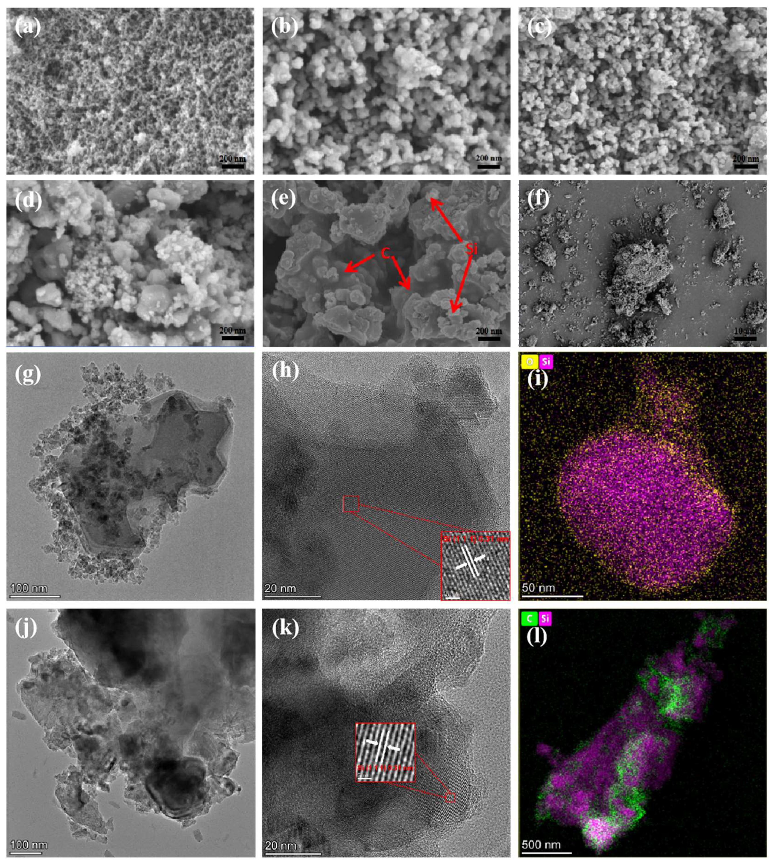
3.1. Morphology and Microstructure Analysis

Figure 1 shows the preparation procedure of bi-continuous Si/C composite anode materials, and photos of the silica aerogel, mesoporous Si matrix, and bi-continuous Si/C anode material are presented in Figure S1. This designed process possesses the merit of facileness and controllability. Silica aerogel with a mesoporous structure is synthesized by the sol–gel method with supercritical drying. A modified magnesiothermic reduction reduces the mesoporous silica aerogel to mesoporous silicon. The mesoporous silicon is further impregnated with pitch, and the pitch is carbonized into carbon to construct bi-continuous Si/C composite anode materials.
SEM and TEM tests were performed to demonstrate the microstructure of the obtained samples. Figure 2a displays an SEM image of silica aerogels prepared via the sol–gel process. Unlike traditional network structures, as-obtained silica aerogels feature skeletons formed by pearls-on-a-string-like nanoparticles, shaping unique ampulliform mesopores. The skeletons are relatively thin and fragile, which becomes a challenge for subsequent magnesiothermic reduction. Massive heat released during this process may cause irreversible damage to the pore structure. Therefore, the reduction time was adjusted to explore the optimal process, enabling both thorough reduction and preservation of the mesoporous structure to be achieved simultaneously. Figure 2b–d depict the SEM images of the obtained samples after being reduced for 6, 12, and 18 h (m-Si-6, m-Si-12, and m-Si-18), respectively. It is shown that when the reduction time is 6 or 12 h, the thin skeleton of the original silica aerogel changes slightly and the expected mesoporous structure of Si is obtained. However, when the reduction time increases to 18 h, the skeletons undergo significant growth, resulting in the collapse and blockage of the mesoporous structure.
Transmission electron microscopy (TEM) was applied to observe the nanoscale structure of the samples. Figure 2g,h show low- and high-magnification TEM images of m-Si-12. The porous structure of synthesized Si can be seen from the figures, and small particles scattered around the Si bulk are formed by the crushing of Si during the reduction process. The clear lattice fringe with a spacing of 0.31 nm is in agreement with that of the (1 1 1) plane of Si, clearly confirming the single crystalline nature of the synthesized Si. Figure 2i shows the EDS image of m-Si-12, and it can be concluded that the synthesized Si has a uniform composition, with only a tiny amount of oxygen distributed around it. Figure 2j–l show the low- and high-magnification TEM images and EDS images of b-Si/C-12. The microstructure of carbon filling can be seen from the above figures, and the thickness of the external carbon layer is about 5 nm. Figure 2l shows the composition distribution of Si/C samples. It can be seen that the pitch-derived carbon and Si matrix intersect with each other, forming the as-said bi-continuous Si/C structure.
XRD images are presented in Figure 3a. As shown in the figure, the distinct broad diffraction peak at 2θ = 23° of silica aerogel indicates that silica aerogels synthesized by the sol–gel method are amorphous. For mesoporous silicon prepared with different reduction times, the sharp diffraction peaks at 28.4°, 47.3°, 56.1°, 69.1°, 76.3°, and 88.0° correspond to the (1 1 1), (2 2 0), (3 1 1), (4 0 0), (3 3 1), and (4 4 2) planes of the Si crystal (space group: Fd3 m ¯ , JCPDS:27-1402), respectively [32]. This confirms that crystalline Si can be prepared by magnesiothermic reduction. However, the difference in the diffraction peaks of m-Si-6, m-Si-12, and m-Si-18 can be clearly seen from the graph. The peak height of m-Si-6 is significantly weaker than that of m-Si-12 and m-Si-18, suggesting that the reduction time of 6 h is insufficient to convert amorphous silica into highly crystalline silicon, and it can be further speculated that there may still be insufficient reduced silica in the m-Si-6 [33]. For the b-Si/C-12, due to the addition of pitch, a significant diffraction peak appeared at 26.6°, corresponding to the (0 0 6) plane of carbon (JCPDS:26-1076). During the magnesiothermic reduction, various byproducts are generated due to the different vapor pressures of magnesium. MgSiO3 and Mg2SiO4 will be generated if the magnesium vapor pressure is insufficient. When the vapor pressure of magnesium is too high, the generated silicon will continue to react with the excess magnesium, generating the byproduct of Mg2Si to decrease the yield of silicon. Some inapparent peaks at 35.8°, 41.8°, and 71.5° in the XRD patterns correspond to the (1 3 1), (1 1 2) and (4 3 1) planes of Mg2SiO4. All byproducts, including MgO and unreacted Mg powder, can be removed by HCl easily. The chemical reaction of magnesiothermic reduction can be described as:
SiO2 (s) + 2/3Mg (g) = 2/3MgSiO3 (s) + 1/3Si (s)
SiO2 (s) + Mg (g) = 1/2Mg2SiO4 (s) + 1/2Si (s)
SiO2 (s) + 2Mg (g) = 2MgO (s) + Si (s)
X-ray photoelectron spectroscopy (XPS) was used to prove the chemical states of Si, O, and C elements in the b-Si/C-12. Figure 3c shows an overall XPS spectrum for peaks of C (C 1s), O (O 1s), and Si (Si 2p, Si 2s) elements, indicating that the final product consists of Si, O, and C elements. As Figure 3d depicts, peaks occur at 284.8 eV and 286.5 eV, which can perfectly match the XPS spectrum of C 1s. The two peaks are in accordance with C-C and C=O bonds, respectively [34]. Figure 3e shows another symmetrical peak located at 532.4 eV of O 1s, which can be assigned to the Si-O bond. It can further confirm the existence of SiO2. The Si 2p XPS spectrum (Figure 3f) can be divided into two peaks. One is the Si-Si bond located at 98.5 eV and the other is the Si-O bond located at 102.4 eV [35].
FTIR was implemented to further identify the functional groups of all samples, and the results are presented in Figure 3b. In the FTIR spectrum, the peaks that occur at 1078, 951, and 452 cm−1 are due to the symmetric stretching, asymmetric stretching, and bending vibrations of Si-O-Si [36]. Peaks located at 3431 cm−1 are attributed to the O-H stretching vibration of H2O due to insufficient drying. The peak that appears separately at 951 cm−1 in the silica aerogel diagram is due to the stretching vibration of the Si-O bond.
The pore size distribution curves and N2 adsorption–desorption isotherms of silica aerogels, m-Si-12, and b-Si/C-12 are shown in Figure 4. According to the IUPAC classification, the N2 adsorption–desorption hysteresis loop of these three samples can perfectly conform to the typical characteristics of IV type with an apparent capillary condensation step, indicating the existence of uniform mesopores [37]. It can be noted that the BET surface area decreases from 864.08 (original silica aerogels) to 245.37 m2 g−1 (mesoporous silicon) after magnesiothermic reduction, indicating that the heat treatment process inevitably results in the collapse of some pores and thus decreases the BET surface area. Compared to previous research [29], in which the BET surface area decreased from 1038.8 to 107.1 m2 g−1, it can be proven that this work is a dramatic improvement in terms of maintaining the integrity of mesopores. The BET surface area of porous silicon decreased to 13.43 m2 g−1 after subsequent filling with molten pitch, indicating that pitch-derived carbon was filled into the Si matrix. The pore volume shows a decreasing trend with the process of magnesiothermic reduction and the impregnation of molten pitch, from the initial 2.84 cm3 g−1 (silica aerogels) to 0.74 cm3 g−1 (m-Si-12), and finally to 0.04 cm3 g−1 (b-Si/C-12), indirectly implying that the internal pores of porous silicon are filled with carbon and the bi-continuous Si/C is successfully synthesized. The pore size of these three samples ranges from 10 to 30 nm, all belonging to the mesoporous structure.

3.2. Electrochemical Properties

Cyclic voltammetry (CV) curves for the first three cycles of the sample b-Si/C-12 were conducted at a scan rate of 0.5 mV s−1 with a potential range of 0.01–3.00 V versus Li/Li+. Figure 5a shows the potential range of 0.01–1 V, and Figure S3 displays the potential range of 0.01–3 V. The SEI layer formed by the reaction between the electrolyte and the anode materials results in a broad peak located at 0.9V as shown in Figure 5a [38,39]. However, it disappeared in the subsequent loop, indicating that the establishment of a stable SEI layer was completed in the first cycle [40]. A large amount of Li+ is consumed during the formation of the SEI layer and this process will reduce the initial Coulombic efficiency. In the molten pitch filling method, the pitch is decomposed into carbon and adhered to the surface of silicon, avoiding direct contact between silicon and the electrolyte, thereby preventing the continuous loss of Li+. Another peak below 0.1 V in the first cathodic scan can be ascribed to the lithiation of silicon, forming LixSi [41]. Subsequently, the formed LixSi alloy undergoes a delithiation reaction and transforms into amorphous silicon, which can be reflected by the broad oxidation peak at 0.5V in Figure 5a [42]. In the subsequent cycles, the peak intensity of the CV curve escalates, indicating the progress of the activation process [43,44]. The other parts of the CV curve remain relatively stable, indicating that the b-Si/C-12 sample has perfect stability during the lithiation/delithiation process.
Electrochemical impedance spectroscopy (EIS) was conducted to investigate the conductivity of the anode. As demonstrated in Figure 5b, both Si and Si/C samples show a semicircle in the high-frequency range and a straight line in the low-frequency range. An equivalent circuit can effectively simulate this behavior and the Rs, Rct, and W represent the resistance for lithium ion transport in the electrolyte, charge transfer resistance, and Warburg impedance, respectively [45,46,47]. The fitting results of EIS curves were calculated and are listed in Table S1 and the bode impedance plots are presented in Figure S4. It can be seen that the Rct value of the b-Si/C-12 sample (~161.1 Ω) is significantly lower than that of b-Si/C-6 (~211.2 Ω) and b-Si/C-18 (~191.7 Ω), indicating the most negligible electrochemical reaction resistance and the highest transfer efficiency of Li+ ions. A uniform mesoporous structure is very helpful to the rapid transportation of Li+ ions, and the carbon fillers can also facilitate electron transportation in the Si/C anode.
Figure 5c displays the rate performances of b-Si/C-6, b-Si/C-12, and b-Si/C-18. Compared to samples b-Si/C-6 and b-Si/C-18, the b-Si/C-12 sample exhibits the best rate capacity at all current densities. Due to the formation of the SEI layer, all three samples show significant capacity decay in the first ten cycles. Compared to the other two samples, the initial capacity of b-Si/C-6 is significantly lower, which results from residual SiO2 due to insufficient reduction time. When the current density increases to 0.2 A g−1, the capacity of the b-Si/C-18 sample shows a significant decrease, only 580 mAh g−1, similar to the b-Si/C-6 sample. Excessive reduction time destroys pore structure, which in turn affects the stability of the sample. In contrast, the b-Si/C-12 sample has a capacity of 817 mAh g−1 at a current density of 0.2 A g−1. As the current density continues to increase, the b-Si/C-12 sample still maintains the optimal rate capacity, which may be attributed to its uniform 3D mesoporous structure and high conductivity of carbon. As the current density returns to 0.1 A g−1, the capacity of the b-Si/C-12 electrode recovers to 610 mAh g−1, higher than the other two samples.
The charge/discharge curves of b-Si/C-12 are exhibited in Figure 5d, which shows profiles of the voltage versus capacity of the 1st, 2nd, 5th, 10th, and 50th cycle at a current density of 300 mA g−1. The voltage window ranges from 0.01 to 0.8 V. As shown in the figure, the discharge and charge capacities in the first cycle are 1481 and 1215 mAh g−1, respectively, corresponding to a calculated first Coulombic efficiency of 82%. Although the initial reversible capacity of the synthesized sample is lower than that of pure silicon (the first discharge and charge capacities of pure silicon are 2729 and 2232 mAh g−1, respectively, and the results are presented in Figure S2), the capacity decay amplitude of the synthesized sample is much lower than that of pure silicon, indicating its reliable stability. Slope charge plateaus between 0.8 and 0.2 V can be attributed to the formation of the SEI layer [48], which disappears in subsequent cycles. Another voltage platform is below 0.1V, which is related to the lithiation of silicon and crystalline silicon transformed into amorphous LixSi [38]. The discharge and charge capacities of the tenth cycle are 1175 and 1159 mAh g−1, respectively, with a Coulombic efficiency approaching 100%. When the cycle number reaches 50 cycles, the discharge and charging capacity decay to 1001 and 992 mAh g−1, respectively, and the Coulombic efficiency remains close to 100%.
The cycling stability and Coulombic efficiency of the b-Si/C-6, b-Si/C-12, and b-Si/C-18 electrode samples are shown in Figure 5e. The test was conducted at a current density of 300 mA g−1 (the current density of the first three cycles was 100 mA g−1) and the long-term cycle performance of b-Si/C-12 is presented in Figure S5. All three electrodes exhibit superior initial Coulombic efficiency, and b-Si/C-6, b-Si/C-12, and b-Si/C-18 electrodes correspond to 82.36%, 82.04%, and 83.11%, respectively, which is approximately 10% higher than the same type of Si/C electrodes. This may benefit from the rich mesoporous structure in the Si/C sample, and the mesoporous structure provides a place for the uniform distribution of molten pitch, thereby avoiding the formation of unstable SEI layers due to direct contact between Si and the electrolyte. The Coulombic efficiency of the three electrodes in subsequent cycles is close to 100%. Overall, the b-Si/C-12 electrode exhibits the highest capacity and optimal cycling stability compared with the b-Si/C-6 electrode, which has a slightly lower capacity and similar stability, and the b-Si/C-18 electrode exhibits poor cycling stability. The initial discharge capacities of the three electrodes are 1272.2, 1481.7, and 1368.9 mAh g−1. The capacity retention is 75%, 68%, and 55% after 200 cycles. The residual silica in b-Si/C-6 resulted in its lower capacity but improved stability. Thus, it is necessary to extend the reduction time to ensure the purity of silicon and thereby increase the capacity of the anode material. However, excessive reduction time may bring about another problem—the destruction of the pore structure, which fails to provide adequate space to accommodate the volume expansion of silicon. This is the reason for the poor cycling stability of the b-Si/C-18 electrode.
Commercial microscale silicon powder’s first discharge and charge capacities are 2996 and 2617 mAh g−1, respectively [29]. According to relevant reports, its initial Coulombic efficiency can reach 87.3%, which may be attributed to its centroid structure. The low specific surface area prevents it from fully contacting the electrolyte, forming very few SEI layers. However, there is too little space to cope with the huge volume expansion of silicon during the cycling process, resulting in poor cycling stability, which decreases to 316.9 mAh g−1 only 10 cycles later. The electrochemical performance of mesoporous pure silicon is presented in Figure S2. The initial discharge and charge capacities of pure silicon prepared by magnesiothermic magnesium are 2729 and 2232 mAh g−1, respectively, which are lower than the theoretical capacity of silicon. This may be caused by residual silica. The capacity of pure mesoporous silicon decreases to 383 mAh g−1 after 200 cycles, which greatly improves stability compared to commercial silicon powder. However, this is still far from commercial applications, so it can be coated with molten asphalt and graphite to endow a better comprehensive electrochemical performance.
Table S2 shows an overview of recent research on Si-based anodes. Through reliable data comparison, this work has certain advantages regarding comprehensive electrochemical performance. These advances are mainly attributed to the design of the bi-continuous structure: (1) the Si matrix can supply sufficient reversible capacity for anode material; (2) pitch-derived carbon penetrating through the matrix can provide a space for the expansion of Si during the cycling process; (3) carbon in the structure facilitates fast lithium ion transfer, thereby improving the conductivity; and (4) this structure can effectively avoid direct contact between Si and the electrolyte, minimizing side reactions between them. Therefore, bi-continuous Si/C anode has excellent application prospects in the field of anodes for advanced lithium-ion batteries.

4. Conclusions

In summary, bi-continuous Si/C composite anode materials are successfully synthesized via simple magnesiothermic reduction of silica aerogels coupled with pitch impregnation and carbonization. The magnesiothermic reduction reduces silica aerogel into a mesoporous Si matrix, while the pitch-derived carbon is uniformly filled into the mesoporous Si matrix. This approach preserves the mesoporous structure and pitch impregnation to construct the final bi-continuous structure. The resultant bi-continuous Si/C anode material displays a high initial discharge capacity of 1481.7 mAh g−1 with an initial Coulombic efficiency of 82%, and the reversible capacity is 813.5 mAh g−1 after 200 cycles at a current density of 300 mA g−1. At a current density of 1 A g−1, bi-continuous Si/C anode material maintains a discharge capacity of 477.5 mAh g−1, demonstrating good rate performance. Pitch-derived carbon injected into the Si matrix assists the transportation of lithium ions and electrons and avoids direct contact between Si and the electrolyte, improving the cycling stability of LIBs. The bi-continuous structure provides an effective solution for the volume expansion of Si during the cycling process. Therefore, bi-continuous Si/C anode material has great potential applications in high-performance lithium-ion batteries.

Supplementary Materials

The following supporting information can be downloaded at https://www.mdpi.com/article/10.3390/batteries9110551/s1. Figure S1: Actual photos of (a) silica aerogels, (b) mesoporous Si, (c) Si/C; Figure S2: (a) Cycle performance of the pure Si at current density of 300 mAh g−1. (b) Charge/discharge curves of pure Si at current density of 300 mAh g−1; Figure S3: CV curves of the b-Si/C-12 electrode at a scan rate of 0.5 mV s−1; Figure S4: Bode impedance plots of (a) b-Si/C-6, (b) b-Si/C-12, and (c) b-Si/C-18; Figure S5: Cycle performance of b-Si/C-12 at a current density of 300 mA g−1 (500 cycles); Table S1: Fitting results of the EIS curves; Table S2: Previous works on Si-based anode in recent years. References [49,50,51,52] are cited in the supplementary materials.

Author Contributions

Conceptualization and methodology, Y.S., J.W. and Z.X.; writing—original draft preparation, Y.S. and S.B.; writing—review and editing, X.G. and X.W.; visualization, Y.Z., Z.X. and J.W.; supervision, X.G. and X.W. All authors have read and agreed to the published version of the manuscript.

Funding

This research was funded by the National Science Foundation of China (21875217 and 51372225) and the China Nation Petroleum Corporation Research Fund Program (RIPED.CN-2022-CL-187).

Institutional Review Board Statement

Not applicable.

Data Availability Statement

Data are contained within the article.

Conflicts of Interest

The authors declare no conflict of interest.

References

  1. Shen, L.; Xu, C.; Gao, J.; Tao, J.; Zhang, Q.; Chen, Y.; Lin, Y.; Huang, Z.; Li, J. Scalable synthesized high-performance TiO2-Si-C hybrid anode for lithium batteries. J. Energy Chem. 2023, 77, 348–358. [Google Scholar] [CrossRef]
  2. Xu, C.; Shen, L.; Zhang, W.; Huang, Y.; Sun, Z.; Zhao, G.; Lin, Y.; Zhang, Q.; Huang, Z.; Li, J. Efficient implementation of kilogram-scale, high-capacity and long-life Si-C/TiO2 anodes. Energy Storage Mater. 2023, 56, 319–330. [Google Scholar] [CrossRef]
  3. Zhang, M.; Zhao, L.; Sun, D.; Sun, Y.; Xu, C.; Lu, S.; Li, T.; Li, Y.; Xiao, Z. S doped CNTs scaffolded Si@C spheres anode toward splendid High-Temperature performance in Lithium-ion Battery. Appl. Surf. Sci. 2023, 626, 157254. [Google Scholar] [CrossRef]
  4. He, X.; Mu, X.; Wang, Y.; Wang, P.; He, P. Fast and Scalable Complete Chemical Prelithiation Strategy for Si/C Anodes Enabling High-Performance LixSi–S Full Cells. ACS Appl. Energy Mater. 2023, 6, 6790–6796. [Google Scholar] [CrossRef]
  5. Song, J.; Chen, Y.; Li, Y.; Sun, P.; Chen, J.; Sui, Z.; Tian, Q.; Zhang, W. Cobalt-embedded porous carbon derived from a facile in-situ strategy enables improved lithium storage performance of silicon anode. J. Alloys Compd. 2023, 958, 170518. [Google Scholar] [CrossRef]
  6. Han, J.; Zhao, C.; Wang, L.; Song, J.; Yang, D.; Tian, Q. Simple ball milling-assisted method enabling N-doped carbon embedded Si for high performance lithium-ion battery anode. J. Alloys Compd. 2023, 966, 171668. [Google Scholar] [CrossRef]
  7. Li, L.; Fang, C.; He, G.; Huang, Y. Surface Chemistry-Controlled SEI Layer on Silicon Electrodes by Regulating Electrolyte Decomposition. ACS Appl. Mater. Interfaces 2023, 15, 36344–36355. [Google Scholar] [CrossRef]
  8. Huey, Z.; Ha, Y.; Frisco, S.; Norman, A.; Teeter, G.; Jiang, C.-S.; DeCaluwe, S.C. Multi-modal characterization methods of solid-electrolyte interphase in silicon-graphite composite electrodes. J. Power Sources 2023, 564, 232804. [Google Scholar] [CrossRef]
  9. Xu, X.; Martín-Yerga, D.; Grant, N.E.; West, G.; Pain, S.L.; Kang, M.; Walker, M.; Murphy, J.D.; Unwin, P.R. Interfacial Chemistry Effects in the Electrochemical Performance of Silicon Electrodes under Lithium-Ion Battery Conditions. Small 2023, 19, 2303442. [Google Scholar] [CrossRef]
  10. Wang, X.; Li, Y.; Wang, X.; Gan, Q.; Wang, Z.; Liao, K.; Wu, S.; Guo, H.; Li, J.; Huang, B.; et al. Carbon-coating strengthens the solid electrolyte interphase to inhibit Si pulverization. J. Mater. Chem. A 2023, 11, 9807–9815. [Google Scholar] [CrossRef]
  11. Xu, Y.; Swaans, E.; Chen, S.; Basak, S.; Harks, P.P.R.M.L.; Peng, B.; Zandbergen, H.W.; Borsa, D.M.; Mulder, F.M. A high-performance Li-ion anode from direct deposition of Si nanoparticles. Nano Energy 2017, 38, 477–485. [Google Scholar] [CrossRef]
  12. Salvatierra, R.V.; Raji, A.-R.O.; Lee, S.-K.; Ji, Y.; Li, L.; Tour, J.M. Silicon Nanowires and Lithium Cobalt Oxide Nanowires in Graphene Nanoribbon Papers for Full Lithium Ion Battery. Adv. Energy Mater. 2016, 6, 1600918. [Google Scholar] [CrossRef]
  13. Wang, W.; Gu, L.; Qian, H.; Zhao, M.; Ding, X.; Peng, X.; Sha, J.; Wang, Y. Carbon-coated silicon nanotube arrays on carbon cloth as a hybrid anode for lithium-ion batteries. J. Power Sources 2016, 307, 410–415. [Google Scholar] [CrossRef]
  14. Ryu, J.; Hong, D.; Choi, S.; Park, S. Synthesis of Ultrathin Si Nanosheets from Natural Clays for Lithium-Ion Battery Anodes. ACS Nano 2016, 10, 2843–2851. [Google Scholar] [CrossRef]
  15. Li, X.; Yan, P.; Arey, B.W.; Luo, W.; Ji, X.; Wang, C.; Liu, J.; Zhang, J.-G. A stable nanoporous silicon anode prepared by modified magnesiothermic reactions. Nano Energy 2016, 20, 68–75. [Google Scholar] [CrossRef]
  16. Ge, M.; Rong, J.; Fang, X.; Zhang, A.; Lu, Y.; Zhou, C. Scalable preparation of porous silicon nanoparticles and their application for lithium-ion battery anodes. Nano Res. 2013, 6, 174–181. [Google Scholar] [CrossRef]
  17. Nie, P.; Liu, X.; Fu, R.; Wu, Y.; Jiang, J.; Dou, H.; Zhang, X. Mesoporous Silicon Anodes by Using Polybenzimidazole Derived Pyrrolic N-Enriched Carbon toward High-Energy Li-Ion Batteries. ACS Energy Lett. 2017, 2, 1279–1287. [Google Scholar] [CrossRef]
  18. Liu, X.; Miao, R.; Yang, J.; Wang, J.; Bie, Y.; Wang, J.; Nuli, Y. Scalable and Cost-Effective Preparation of Hierarchical Porous Silicon with a High Conversion Yield for Superior Lithium-Ion Storage. Energy Technol. 2016, 4, 593–599. [Google Scholar] [CrossRef]
  19. Yoon, T.; Bok, T.; Kim, C.; Na, Y.; Park, S.; Kim, K.S. Mesoporous Silicon Hollow Nanocubes Derived from Metal-Organic Framework Template for Advanced Lithium-Ion Battery Anode. ACS Nano 2017, 11, 4808–4815. [Google Scholar] [CrossRef]
  20. An, W.; Gao, B.; Mei, S.; Xiang, B.; Fu, J.; Wang, L.; Zhang, Q.; Chu, P.K.; Huo, K. Scalable synthesis of ant-nest-like bulk porous silicon for high-performance lithium-ion battery anodes. Nat. Commun. 2019, 10, 1447. [Google Scholar] [CrossRef]
  21. Zhao, Y.; Liu, X.; Li, H.; Zhai, T.; Zhou, H. Hierarchical micro/nano porous silicon Li-ion battery anodes. Chem. Commun. 2012, 48, 5079–5081. [Google Scholar] [CrossRef] [PubMed]
  22. Akkinepally, B.; Reddy, I.N.; Manjunath, V.; Reddy, M.V.; Mishra, Y.K.; Ko, T.J.; Zaghib, K.; Shim, J. Temperature effect and kinetics LiZr2(PO4)3 and Li1.2Al0.2Zr1.8PO4.3 and electrochemical properties for rechargeable ion batteries. Int. J. Energy Res. 2022, 46, 14116–14132. [Google Scholar] [CrossRef]
  23. Wang, S.E.; Kim, M.J.; Lee, J.W.; Chun, J.; Choi, J.; Roh, K.C.; Kang, Y.C.; Jung, D.S. A Novel High-Performance TiO2−x/TiO1−yNy Coating Material for Silicon Anode in Lithium-Ion Batteries. Small Methods 2022, 6, 2200430. [Google Scholar] [CrossRef] [PubMed]
  24. Liu, G.; Sun, Z.; Shi, X.; Wang, X.; Shao, L.; Liang, Y.; Lu, X.; Liu, J.; Guo, Z. 2D-Layer-Structure Bi to Quasi-1D-Structure NiBi3: Structural Dimensionality Reduction to Superior Sodium and Potassium Ion Storage. Adv. Mater. 2023, 35, 2305551. [Google Scholar] [CrossRef]
  25. Luo, Y.; Wu, S.; Wang, P.; Ranganathan, H.; Shi, Z. Interface engineering of Ni2P/MoO decorated NiFeP nanosheets for enhanced alkaline hydrogen evolution reaction at high current densities. J. Colloid Interface Sci. 2023, 648, 551–557. [Google Scholar] [CrossRef]
  26. Halmann, M. Vacuum Carbothermic Production of Aluminum and Al-Si Alloys From Kaolin Clay: A Thermodynamic Study. Miner. Process. Extr. Metall. Rev. 2013, 35, 106–116. [Google Scholar] [CrossRef]
  27. Kikuchi, T.; Ishida, R.; Natsui, S.; Kumagai, T.; Ogino, I.; Sakaguchi, N.; Ueda, M.; Suzuki, R.O. Carbon Nanotube Synthesis via the Calciothermic Reduction of Carbon Dioxide with Iron Additives. ECS Solid State Lett. 2015, 4, M19–M22. [Google Scholar] [CrossRef]
  28. Jia, H.; Li, X.; Song, J.; Zhang, X.; Luo, L.; He, Y.; Li, B.; Cai, Y.; Hu, S.; Xiao, X.; et al. Hierarchical porous silicon structures with extraordinary mechanical strength as high-performance lithium-ion battery anodes. Nat. Commun. 2020, 11, 1474. [Google Scholar] [CrossRef]
  29. Li, Q.; Yin, L.; Gao, X. Reduction chemical reaction synthesized scalable 3D porous silicon/carbon hybrid architectures as anode materials for lithium ion batteries with enhanced electrochemical performance. RSC Adv. 2015, 5, 35598–35607. [Google Scholar] [CrossRef]
  30. Kim, H.; Han, B.; Choo, J.; Cho, J. Three-dimensional porous silicon particles for use in high-performance lithium secondary batteries. Angew. Chem. Int. Ed. Engl. 2008, 47, 10151–10154. [Google Scholar] [CrossRef]
  31. Wang, B.; Li, W.; Wu, T.; Guo, J.; Wen, Z. Self-template construction of mesoporous silicon submicrocube anode for advanced lithium ion batteries. Energy Storage Mater. 2018, 15, 139–147. [Google Scholar] [CrossRef]
  32. Tao, H.; Fan, L.Z.; Song, W.L.; Wu, M.; He, X.; Qu, X. Hollow core-shell structured Si/C nanocomposites as high-performance anode materials for lithium-ion batteries. Nanoscale 2014, 6, 3138–3142. [Google Scholar] [CrossRef] [PubMed]
  33. Luo, W.; Wang, X.; Meyers, C.; Wannenmacher, N.; Sirisaksoontorn, W.; Lerner, M.M.; Ji, X. Efficient fabrication of nanoporous si and Si/Ge enabled by a heat scavenger in magnesiothermic reactions. Sci. Rep. 2013, 3, 2222. [Google Scholar] [CrossRef]
  34. Ma, B.; Lu, B.; Luo, J.; Deng, X.; Wu, Z.; Wang, X. The hollow mesoporous silicon nanobox dually encapsulated by SnO2/C as anode material of lithium ion battery. Electrochim. Acta 2018, 288, 61–70. [Google Scholar] [CrossRef]
  35. Huang, Y.; Li, W.; Peng, J.; Wu, Z.; Li, X.; Wang, X. Structure Design and Performance of the Graphite/Silicon/Carbon Nanotubes/Carbon (GSCC) Composite as the Anode of a Li-Ion Battery. Energy Fuels 2021, 35, 13491–13498. [Google Scholar] [CrossRef]
  36. Fan, W.; Gao, L. Synthesis of silica hollow spheres assisted by ultrasound. J. Colloid Interface Sci. 2006, 297, 157–160. [Google Scholar] [CrossRef]
  37. Guo, X.; Li, Z.; Lei, W.; Ding, R.; Zhang, Y.; Yang, H. Rapid Preparation of Mesoporous Methylsilsesquioxane Aerogels by Microwave Heating Technology. Molecules 2021, 26, 1960. [Google Scholar] [CrossRef]
  38. Wang, X.; Wen, K.; Chen, T.; Chen, S.; Zhang, S. Supercritical fluid-assisted preparation of Si/CNTs@FG composites with hierarchical conductive networks as a high-performance anode material. Appl. Surf. Sci. 2020, 522, 146507. [Google Scholar] [CrossRef]
  39. Zhang, H.; Zhang, X.; Jin, H.; Zong, P.; Bai, Y.; Lian, K.; Xu, H.; Ma, F. A robust hierarchical 3D Si/CNTs composite with void and carbon shell as Li-ion battery anodes. Chem. Eng. J. 2019, 360, 974–981. [Google Scholar] [CrossRef]
  40. Liu, W.; Hu, Y.; Qiao, Y.; Jiang, J.; Huang, M.; Qu, M.; Peng, G.; Xie, Z. 1-Aminopyrene-modified functionalized carbon nanotubes wrapped with silicon as a high-performance lithium-ion battery anode. Solid State Ion. 2021, 369, 115724. [Google Scholar] [CrossRef]
  41. Park, G.D.; Choi, J.H.; Jung, D.S.; Park, J.-S.; Kang, Y.C. Three-dimensional porous pitch-derived carbon coated Si nanoparticles-CNT composite microsphere with superior electrochemical performance for lithium ion batteries. J. Alloys Compd. 2020, 821, 153224. [Google Scholar] [CrossRef]
  42. Liang, J.; Li, X.; Hou, Z.; Zhang, W.; Zhu, Y.; Qian, Y. A Deep Reduction and Partial Oxidation Strategy for Fabrication of Mesoporous Si Anode for Lithium ion Batteries. ACS Nano 2016, 10, 2295–2304. [Google Scholar] [CrossRef] [PubMed]
  43. Zhu, X.; Choi, S.H.; Tao, R.; Jia, X.; Lu, Y. Building high-rate silicon anodes based on hierarchical Si@C@CNT nanocomposite. J. Alloys Compd. 2019, 791, 1105–1113. [Google Scholar] [CrossRef]
  44. Luo, Z.; Xiao, Q.; Lei, G.; Li, Z.; Tang, C. Si nanoparticles/graphene composite membrane for high performance silicon anode in lithium ion batteries. Carbon 2016, 98, 373–380. [Google Scholar] [CrossRef]
  45. Ma, T.; Xu, H.; Yu, X.; Li, H.; Zhang, W.; Cheng, X.; Zhu, W.; Qiu, X. Lithiation Behavior of Coaxial Hollow Nanocables of Carbon-Silicon Composite. ACS Nano 2019, 13, 2274–2280. [Google Scholar] [CrossRef]
  46. Yang, Y.; Li, J.; Chen, D.; Fu, T.; Sun, D.; Zhao, J. Binder-Free Carbon-Coated Silicon-Reduced Graphene Oxide Nanocomposite Electrode Prepared by Electrophoretic Deposition as a High-Performance Anode for Lithium-Ion Batteries. ChemElectroChem 2016, 3, 757–763. [Google Scholar] [CrossRef]
  47. Wang, M.-S.; Wang, Z.-Q.; Jia, R.; Yang, Y.; Zhu, F.-Y.; Yang, Z.-L.; Huang, Y.; Li, X.; Xu, W. Facile electrostatic self-assembly of silicon/reduced graphene oxide porous composite by silica assist as high performance anode for Li-ion battery. Appl. Surf. Sci. 2018, 456, 379–389. [Google Scholar] [CrossRef]
  48. Shi, J.; Jiang, X.; Ban, B.; Li, J.; Chen, J. Carbon nanotubes-enhanced lithium storage capacity of recovered silicon/carbon anodes produced from solar-grade silicon kerf scrap. Electrochim. Acta 2021, 381, 138269. [Google Scholar] [CrossRef]
  49. Wang, M.-S.; Fan, L.-Z. Silicon/carbon nanocomposite pyrolyzed from phenolic resin as anode materials for lithium-ion batteries. J. Power Sources 2013, 244, 570–574. [Google Scholar] [CrossRef]
  50. Shen, L.; Guo, X.; Fang, X.; Wang, Z.; Chen, L. Magnesiothermically reduced diatomaceous earth as a porous silicon anode material for lithium ion batteries. J. Power Sources 2012, 213, 229–232. [Google Scholar] [CrossRef]
  51. Kong, X.; Luo, S.; Rong, L.; Xie, X.; Zhou, S.; Chen, Z.; Pan, A. Enveloping a Si/N-doped carbon composite in a CNT-reinforced fibrous network as flexible anodes for high performance lithium-ion batteries. Inorg. Chem. Front. 2021, 8, 4386–4394. [Google Scholar] [CrossRef]
  52. Han, N.; Li, J.; Wang, X.; Zhang, C.; Liu, G.; Li, X.; Qu, J.; Peng, Z.; Zhu, X.; Zhang, L. Flexible Carbon Nanotubes Confined Yolk-Shelled Silicon-Based Anode with Superior Conductivity for Lithium Storage. Nanomaterials 2021, 11, 699. [Google Scholar] [CrossRef] [PubMed]
Figure 1. Schematic representation of bi-continuous Si/C composite anode materials.
Batteries 09 00551 g001
Figure 2. SEM images of (a) silica aerogels, (b) m-Si-6, (c) m-Si-12, (d) m-Si-18, and (e,f) b-Si/C-12. Low-magnification (g) and high-magnification (h) TEM images of m-Si-12. (i) EDS image of m-Si-12. Low-magnification (j) and high-magnification (k) TEM images of b-Si/C-12. (l) EDS image of b-Si/C-12.
Batteries 09 00551 g002
Figure 3. (a) XRD patterns of silica aerogel, mesoporous silicon, and Si/C samples. (b) FTIR spectra of silica aerogel, m-Si-12, and b-Si/C-12 samples. XPS spectra of b-Si/C-12 for (c) survey spectrum, (d) C 1s, (e) O 1s, (f) Si 2p.
Batteries 09 00551 g003
Figure 4. Nitrogen adsorption–desorption isotherms of (a) silica aerogels, (c) m-Si-12, (e) b-Si/C-12, and the pore size distribution of (b) silica aerogels, (d) m-Si-12, (f) b-Si/C-12.
Batteries 09 00551 g004
Figure 5. Electrochemical characterization of bi-continuous Si/C anodes in half-cell configurations. (a) CV curves of the b-Si/C-12 electrode at a scan rate of 0.5 mV s−1. (b) Comparison of EIS (inset shows equivalent circuit) between b-Si/C-6, b-Si/C-12, and b-Si/C-18 in the half-cell configurations. (c) Comparison of rate performances between b-Si/C-6, b-Si/C-12, and b-Si/C-18 in the half-cell configurations. (d) Selected voltage profiles and (e) cycle performances of b-Si/C-6, b-Si/C-12, and b-Si/C-18 electrodes at a current density of 300 mA g−1 (100 mA g−1 for the first three cycles).
Batteries 09 00551 g005
Disclaimer/Publisher’s Note: The statements, opinions and data contained in all publications are solely those of the individual author(s) and contributor(s) and not of MDPI and/or the editor(s). MDPI and/or the editor(s) disclaim responsibility for any injury to people or property resulting from any ideas, methods, instructions or products referred to in the content.

