1. Introduction
Within the energy storage landscape, lithium-ion batteries (LIBs) have emerged as standout frontrunners, distinguished by their efficient energy storage, environmental sustainability, comparatively high energy density, extensive cycle life, rapid charging/discharging capabilities, and minimal self-discharge [
1,
2]. Over the past decade, LIBs have found widespread application in consumer electronics, power storage stations, and, more recently, electric vehicles (EVs). LIBs now serve not only small portable electronics like computers and cell phones but also more demanding electric or hybrid-electric vehicles [
3]. However, the currently applied LIBs utilize liquid electrolytes that consist of highly volatile and flammable organic solvents, resulting in safety issues, including the potential for fires and explosions [
4]. These safety concerns have been amplified and highlighted by the application of LIBs in EVs, where the consequences of cell failures are dire. Additionally, the industry needs safer and more cost-effective batteries with higher energy density and longer cycle life [
5]. Hence, the adoption of all-solid-state lithium-ion batteries (ASSLBs) represents a promising breakthrough in battery technology, effectively addressing safety concerns by replacing flammable liquid electrolytes with nonflammable and nonvolatile solid electrolytes (SEs). These inherently safer materials allow ASSLBs to utilize high-capacity lithium metal as an anode, significantly boosting energy density and establishing them a game-changing innovation in the field [
2,
6].
Li
6PS
5X (with X = Cl, B, I) argyrodite-type electrolytes have been the focus of an abundance of research due to their relatively high ionic conductivity and their compatibility with Li-metal anodes. These electrolyte properties are considered as fundamental to the success of ASSLBs; however, so is the compatibility with the cathode electrode and research on this is therefore paramount, because despite the use of high ion-conductivity solid electrolytes in ASSLBs, there remains a significant challenge, namely the need to incorporate approximately 20–40% of SEs within the cathode electrode to increase ion conductivity [
7,
8,
9]. The heightened interest in ASSLB research is due to the breakthrough achieved with sulfide SEs, which exhibit ionic conductivity levels that are comparable to, and in some cases surpass, those of liquid electrolytes, particularly at lower temperatures [
10]. Furthermore, sulfide electrolytes are ductile, with exceptional mechanical properties allowing for high applied pressures, positioning them as highly promising candidates for ASSLBs [
11]. Since the SE does not contribute to energy storage, this leads to a reduction in the energy density of the electrode. Moreover, there is a limitation to adding larger volumes of a micron-sized SEs, as it can obstruct electron conduction pathways within the electrode, causing a decrease in electron conductivity [
12].
To enhance the high rate capability, cost-effective carbon materials with excellent electrical conductivity, like carbon black (CB), carbon nanotubes (CNTs), graphene, and carbon nanofibers (CNF), are mainly incorporated as conductive materials in the cathode electrode because the applied cathode materials often exhibit inadequate inherent electrical conductivity [
13]. In particular, the nanostructured CB is widely used as a cost-effective carbon additive to enhance the electrical conductivity of LIB electrodes, owing to its excellent electrical conductivity, low cost, and dependable electrochemical properties. Therefore, in the context of ASSLB systems, CB additives have naturally become prevalent [
14]. It has been well established, however, that such additives are particularly detrimental to the performance of ASSLBs due to their physical morphology and chemical structures [
15,
16]. In comparison to other forms of carbon, such as vapor-grown carbon fiber (VGCF), the nanosized particles of CB have a greater specific surface area, which accelerates the kinetics of sulfide electrolyte breakdown. The breakdown capacity and kinetics of CB cells have been found to be significantly higher than those of VGCF cells. The considerable body of research to enhance the performance of ASSLBs is focused on increasing the stability window of SE and minimizing the voltage change over cycling, which significantly reduces electrolyte degradation and provides research insights focusing on carbon additive materials [
17]. Therefore, alternatives to carbon additives have been sought, with recent studies introducing CNF as a promising alternative [
6]. Despite the introduction of CNF being generally considered as an improvement, a deep understanding of the underlying reasoning for the electrochemical improvements is lacking and requires significant research efforts. For one, it has generally been acknowledged that the decomposition of SEs is a common issue due to side reactions with all carbon materials as they act as electron carriers; hence, research has attempted to minimize this source of degradation [
2,
14,
18,
19]. However, despite this, due to their electron carrying nature, the sulfide SE cannot withstand the voltage at any carbon material surface due to its low stability window and therefore the continuous degradation results in capacity fade. One way to overcome this is to coat the carbon additive material in order to somewhat reduce the direct contact between electron pathways and the solid electrolyte [
20,
21]. However, these coating processes are expensive and likely to result in a further lowering of the active material wt% in the cathode composite. More importantly, the chemical degradation of SE at the carbon additive/SE interface is certainly not the only carbon additive-related factor affecting the performance of the cathode composites. A pertinent example of this would be the dispersion and location of the carbon additive within the cathode composite. To examine this, the mixing protocol of the cathode composite was analyzed for the Super-P carbon material, and it was determined that the most suitable location for the carbon additive actually maximized the contact with the SE [
22]. Findings such as this highlight that alternative factors outside of carbon additive-induced SE degradation, such as dispersion within the cathode composite, active material to carbon additive contact, and carbon additive morphology can also play a critical role in the cathode performance [
23]. Therefore, to enhance the electrochemical performance, further research is required not only to determine suitable carbon additives to incorporate into cathode composites with sulfide SEs, but to additionally determine the exact properties and interacting mechanisms of such carbon additives that have the most impact on the electrochemical performance.
In this paper, we investigate the distribution of conductive materials and the resulting electrochemical performance of composites incorporating nano-sized CB and micron-sized CNF as conductive materials at 9 wt% of the cathode composite electrode. For the composites, a composition of 64 wt% Ni-rich cathode active material (LiNi0.8Co0.1Mn0.1O2), 27 wt% SEs (Li6PS5Cl argyrodite), and 9 wt% conductive material was used. SEM analysis revealed that, in the case of nano-sized CB, some of the SEs were directly positioned at the cathode material, but the majority of the CB was distributed between the SEs and cathode material surfaces. When composites of identical composition were produced using micron-sized CNF, SEM analysis showed that the CNF allowed for numerous contacts between the SEs and the cathode material, with CNF exhibiting far fewer contacts with the SEs and cathode active materials compared to CB. At a charge/discharge rate of 0.05C (1C: 200 mA/g), the discharge capacity of the composite including CB was 110.2 mAh/g, while the composite with CNF exhibited superior discharge capacity, of 194.7 mAh/g. Furthermore, during the 0.5C cycling, CNF demonstrated better cycle stability over 50 cycles at 78.8%, as opposed to 21.7% for CB. The superior electrochemical performance of the composite with CNF is attributed to the reduction in polarization during cycling when compared to CB, as well as the mitigation of interfacial charge transfer impedance between the cathode materials and the SEs. The results of electrical conductivity analysis using potentiostatic measurements indicated that the composite with CB exhibited higher electrical conductivity compared to the composite with CNF, even though the ionic conductivity of the SEs in the composites was similar. Therefore, we primarily attribute this improvement to the fact that the micron-sized CNF conductive material, in contrast to CB, did not impede the contact between the SEs and the cathode material.
3. Result and Discussion
Nano-sized CB or micron-sized CNF at 9 wt% was mixed with 64 wt% of cathode active material and 27 wt% of SEs, and subsequently pressed into pellets. The pellets were analyzed using scanning electron microscopy (SEM) in back-scattered electron (BSE) mode. In BSE mode, heavier elements (cathode materials) appear brighter, and lighter elements (SEs, carbons) appear darker. Consequently, the cathode active material (NCM811) exhibited the brightest appearance within the composite appearing as a mid-bright grey color; followed by SEs, which appeared as a dull grey; and the carbon-based materials appearing the darkest, with an almost black color. This SEM analysis mode was selected as it allowed for this clear and distinguishable differences to be observed within the cathode active material composite.
Figure 1a shows the BSE-mode SEM image, presenting the surface of the pellet containing CB with a uniform distribution of CB throughout the composite. The zoomed-in SEM image of the white-dotted rectangle in
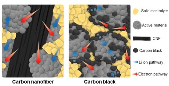
Figure 1a clearly reveals the positioning of the SEs, the cathode active material, and the CB. The CB is frequently observed between the SEs and the cathode active material, as indicated by the red arrows. Both electrical conductivity and ionic conductivity are required at the cathode active material surface and therefore this location could be viewed as of benefit with regard to the electrical conductivity within the system, but of detriment negative because it may come at the cost of the ionic conductivity across this interface. Furthermore, this configuration can accelerate the decomposition of SEs by promoting electronic conduction at the surface [
2], while also acting as a barrier between the SEs and the cathode active material, impeding the movement of lithium ions across the interface. This results in a combination of negative effects occurring at the cathode surface based on the dispersion and morphology of CB within the cathode active material electrode and a poorly optimized cathode composite generally, with the ionic conductivity being neglected. In contrast, when rod-like CNFs with a diameter of approximately ten microns and lengths in the range of several hundred microns were employed as conductive additives, as seen in
Figure 1c,d for pellets containing 9 wt% CNF, the interface between the solid electrolyte and cathode material was not negatively impacted. In fact, the interface between the solid electrolyte and active material seems to remain wholly intact, with ionic pathways shown in the SEM image as a dull grey color being clearly distinguishable. Additionally, the surface area of carbon material in direct contact with the SEs is much lower and hence, the debilitating redox reactions occurring between the electrons carried by the carbon and the SE are likely reduced. The interface between the active material and the conductive additive is also reduced, which could be considered as a negative aspect of the CNF-based composite, in addition to the fact that the CNFs appear as islands within the composite and do not seem to establish close contact with each other. Lastly, the SEM analysis suggests that the morphology of the CNF material creates a tighter cathode composite and therefore an improved interface between the NCM and the SE. When comparing this with the CB composite, we can see that the SE has maintained its spherical particle form and that generally good contact between the NCM and SE is minimal. These contacts are especially important when considering the volume change in electrodes within ASSLBs [
25,
26]. This SEM analysis implies that whilst lithium-ion conduction within the cathode electrode is likely similar or improved upon compared to the CB composite, electronic pathways are relatively poorly connected. Using this information in combination with electrochemical data can help to determine which conductivity, be it electronic or ionic, is the limiting factor within the cathode composite and how careful selection of the carbon additive applied in the cathode composite can determine which of these is maximized.
We evaluated the electrochemical properties of ASSLB configurations utilizing CB or CNF as conductive additives, and compared their initial discharge capacity and cycle performance with LiNi
0.
8Co
0.
1Mn
0.
1O
2 as the cathode material. As shown in
Figure 2a, when CB was used as the conductive additive (CB-composite) and charged/discharged at 0.05C (1C = 200 mA/g), the charging capacity was 187.4 mAh/g and the discharging capacity was 110.2 mAh/g, resulting in an initial Coulombic efficiency (ICE) of 58.8%. (
Table 1). Considering that the ICE can essentially be explained as the availability of lithium ions to return to the cathode host during the initial formation charge/discharge, and the fact that the cathode material is already the capacity limiting factor of the cell, achieving an ICE this low is wholly unsatisfactory. In contrast, using CNF as the conductive additive (CNF-composite) yielded a higher electrochemical performance, with a charging capacity of 225.9 mAh/g, discharging capacity of 194.7 mAh/g, and a significantly improved initial efficiency of 86.2%. The higher charge capacity of the CNF-composite cell indicates that either electrical or ionic isolation may be occurring in the CB-composite cell. Since the previously discussed SEM data appear to show that the CNF-composite has a poorer electrical network, it may be attributable to the ion movement out of the cathode composite. Furthermore, the voltage profiles revealed that CB exhibited an overall large overvoltage during charging, characterized by a long constant voltage (CV) charging stage at 4.3 V and large polarization. In contrast, CNF displayed relatively lower overvoltage, a shorter CV charging stage, and reduced polarization [
13]. All these factors essentially tie together to suggest that the electronic and ion paths of the CNF-composite are better maintained over the charging stage than the CB-composite. When examining the zoomed-in initial charging voltage profile (
Figure 2b), it is evident that the CNF-composite reaches the typical charge potential associated with the cathode material (~3.6 V vs. Li/Li
+) earlier on the x-axis (capacity) than the CB-composite. This implies that CNF is more electrochemically stable with SEs than CB, as any charge occurring below this potential can likely be attributed to SE oxidation reactions [
14]. This provides further explanation for the poor ICE of the CB-composite in comparison to the CNF-composite, as any degradation of the solid electrolyte itself can result in a larger irreversible capacity whether that be directly through interactions with electrons or indirectly through reduction in the ionic conductivity of the composite.
Figure 2c indicates the discharge capacity and Coulombic efficiency over 50 cycles at a charge/discharge rate of 0.5C. For the CB-composite, the initial cycle’s discharge capacity was 61.4 mAh/g. It maintained a capacity of only 16.7 mAh/g at the 50th cycle, equivalent to a retention rate of 27.1% after 50 cycles. The low CE of the CB-composite suggests that the conductive additive may obstruct lithium ion pathways and be a result of decreased ionic conductivity. It could also suggest that side reactions discussed in the formation cycle (
Figure 2b) could continue throughout cycling and be ongoing. The poor CE can be determined to arise from a combination of the distribution location of the CB in the composite and the resulting side reactions with the SE. In contrast, the CNF-composite exhibited superior electrochemical performance, with an initial cycle discharge capacity of 164.5 mAh/g and a capacity of 129.6 mAh/g after 50 cycles, equivalent to a retention rate of 78.8%, which is much higher compared to CB. Note that the capacity retentions were calculated using the 50th cycle data at 0.5C and the 1st cycle data at 0.5C so as to not include the formation capacity, which is conducted at a significantly lower C-rate. Additionally, the Coulombic efficiency of the CNF-composite remained consistently higher than that of the CB-composite throughout the charge–discharge cycle process.
When examining the 0.5C charge–discharge profiles with CB or CNF as conductive additives, distinct differences begin to emerge. The CB-composite exhibits large overvoltage from the first cycle, and charging occurs almost exclusively in the CV mode after 10 cycles. As discussed previously, this can be attributed to a significant build up in the internal resistance of the cell, which continues to increase with cycling (
Figure 3a). In contrast, the CNF-composite displays consistent charging in both constant current (CC) mode and CV mode throughout 50 cycles, with a notable characteristic being that the charging amount in the CC mode surpasses that of the CV mode all the way until the 50th cycle (
Figure 3b). This indicates a particularly effective overvoltage mitigation during the cycling process of the CNF-composite compared to that of the CB-composite.
In order to assess how the conductive additives impact the impedance between the cathode electrode and SEs throughout the charge–discharge cycles, we performed electrochemical impedance spectroscopy (EIS) tests on the CB-composite and the CNF-composite, both immediately after formation and after 50 cycles, as shown in
Figure 4a,b. The Nyquist plots of the ASSLB cathode half-cell system exhibit distinct features, characterized by one semicircle at high frequencies, another at intermediate frequencies, with a final linear segment at low frequencies. The semicircles observed at high and intermediate frequencies are associated with the impedance at the solid electrolyte grain boundaries (R
GB) and the interfacial charge transfer impedance between the cathode materials and solid electrolyte (R
CT) respectively [
27]. The straight line, often referred to as Warburg diffusion (W), represents the ion diffusion directly to and from the electrode surface. The point where the high-frequency curve intersects the Z
re axis corresponds to the bulk impedance (R
bulk) of the solid electrolyte [
28,
29]. That means that the R
bulk can be precisely determined through EIS fitting analysis. The R
bulk values for the CB-composite and the CNF-composite, observed in the high-frequency range, are, respectively, 36.5 Ω and 37.2 Ω after formation and 71.8 Ω and 41.9 Ω after 50 cycles. Since the R
bulk values showed minimal differences, this indicates that the overall lithium ion conductivity of the SEs is similar in both composites [
30]. However, the charge transfer resistance for the CB-composite is 800.5 Ω, while for the CNF-composite, it is 428.1 Ω after 50th cycle (
Table 2). Considering also the analysis of the composite morphology from the SEM analysis in
Figure 1, the increased interfacial resistance within the CB-composite is due to the presence of CB between the solid electrolyte and cathode materials.
The electrical conductivities of the CB-composite and the CNF-composites were determined. This was accomplished through potentiostatic measurements conducted at room temperature, employing stainless steel ion-blocking electrodes (SUS) on either side of the cell and hence inducing electron movement within the composite (
Figure 5a) [
31]. The electrical conductivities of the CB-composite and the CNF-composite are 6.47 × 10
−3 S cm
−1 and 4.25 × 10
−3 S cm
−1, respectively (
Figure 5b) Through EIS analysis, we confirmed that the ionic conductivity of the SEs is similar, and potentiostatic measurements revealed that the electrical conductivity of the composite with CB is higher than that of the composite with CNF. Based on the SEM analysis shown in
Figure 1, and the superior dispersion of the CB within the cathode composite, this could be somewhat expected. However, despite the higher electrical conductivity, the electrochemical performance of the CB-composite is inferior to that of the CNF-composite, indicating that this increase in electrical conductivity comes at too high a cost to the ionic conductivity of the system. In conjunction with these data, the charge transfer impedance in the CB-composite was notably higher after the cycling process. This phenomenon can be attributed to the increase in interfacial resistance due to the location of CB at the interface between the SEs and the cathode material in the CB composite. These findings underscore the importance of minimizing the interfacial resistance between the SEs and the cathode active material to ensure the stable performance of ASSLBs.


 ,
, 


