Review

Review of Active Front-End Rectifiers in EV DC Charging Applications

1
MOBI-EPOWERS Research Group, ETEC Department, Vrije Universiteit Brussel (VUB), Pleinlaan 2, 1050 Brussels, Belgium
2
Flanders Make, 3001 Heverlee, Belgium
*
Authors to whom correspondence should be addressed.
Batteries 2023, 9(3), 150; https://doi.org/10.3390/batteries9030150
Submission received: 9 December 2022 / Revised: 13 February 2023 / Accepted: 25 February 2023 / Published: 27 February 2023

Abstract

:
Active Front-End (AFE) rectifiers have regained momentum as the demand for highpower Electric Vehicle (EV) charging infrastructure increases exponentially. AFE rectifiers have high efficiency and reliability, and they minimize the disturbances that could be generated due to the operation of the EV charging systems by reducing harmonic distortion and operating close to the Unity Power Factor (UPF). The purpose of this review is to present the current state-of-the-art AFE rectifiers used in fast chargers, focusing on the comparison between different AFE topologies and their components, as well as modular AFE solutions. Furthermore, different control strategies of AFE converters are presented and compared. Some of their more widely used control techniques, namely Voltage Oriented Control (VOC), Direct Power Control (DPC), Hysteresis Current Control (HCC), and Model Predictive Control (MPC), have been implemented, and their performance compared. Centralized and distributed control systems are compared for operating parallel AFE rectifiers for modular, fast charging systems. An overview of cooling systems and reliability evaluation tools is also presented. Finally, trends and future outlooks are analyzed.

1. Introduction

A strong focus on reducing global warming has accentuated the need to replace Internal Combustion Engine (ICE) vehicles with emission-free substitutes. Figure 1 shows the growth of the global EV stock by region over ten years, from 2010 to 2020 [1]. Many of the hurdles on the way to the development of EVs are being solved through scientific advancements in the fields of battery technology and Power Electronic Converters (PEC). Increased battery capacity and high-efficiency PEC can improve the vehicle range, while high-power charging ensures that the “re-fueling” time of EVs is comparable to that of conventional ICE vehicles. According to the electric vehicle charging infrastructure market report, the electric vehicle charging station market for public chargers is projected to grow at a compound annual growth rate (CAGR) of 30.6% between the period of 2022 and 2030 in comparison to a 19.26 billion USD valued market size in 2021 [2].
EV chargers can be classified into three levels based on their power rating, as shown in Table 1. Moreover, they are also categorized as on-board and off-board based on their location. On-board chargers have the convenience of being fairly independent of the charging infrastructure and having the freedom to charge at residential or office spaces where the user would be spending time anyway. On-board chargers can be in charger power Levels 1 or 2 because they have space and weight constraints, so their power rating is limited by the power density of the converter. These chargers cannot deliver the same speed of charging as higher power off-board chargers.
Off-board chargers can be in Levels 2 or 3 and deliver up to 400 kW. Nowadays, even faster next-generation ultra-fast chargers that work with voltages above 800 V and deliver power above 400 kW are being studied. According to [2], 93.5% of the charging infrastructure market is held by fast chargers. Moreover, the same report states that during the 2022–2030 period, the DC fast-charging segment is expected to grow at the highest rate.
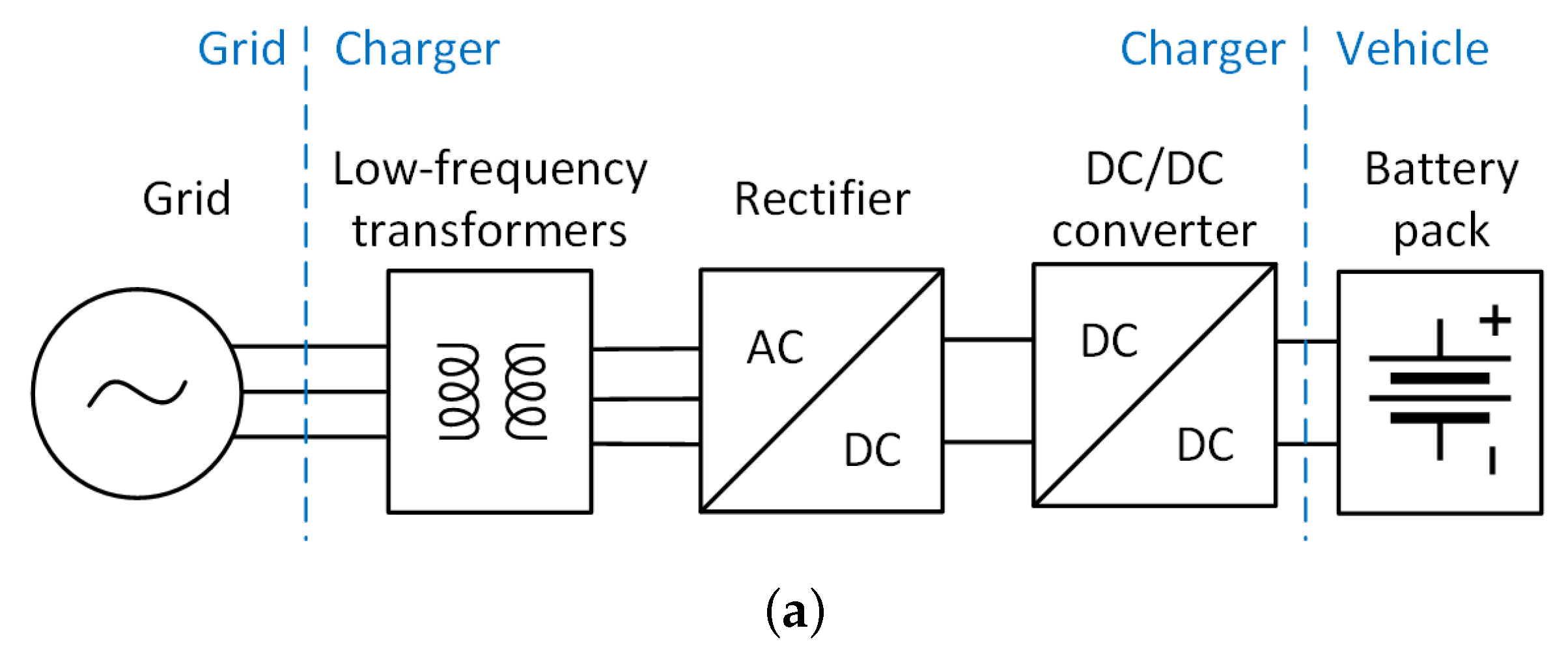
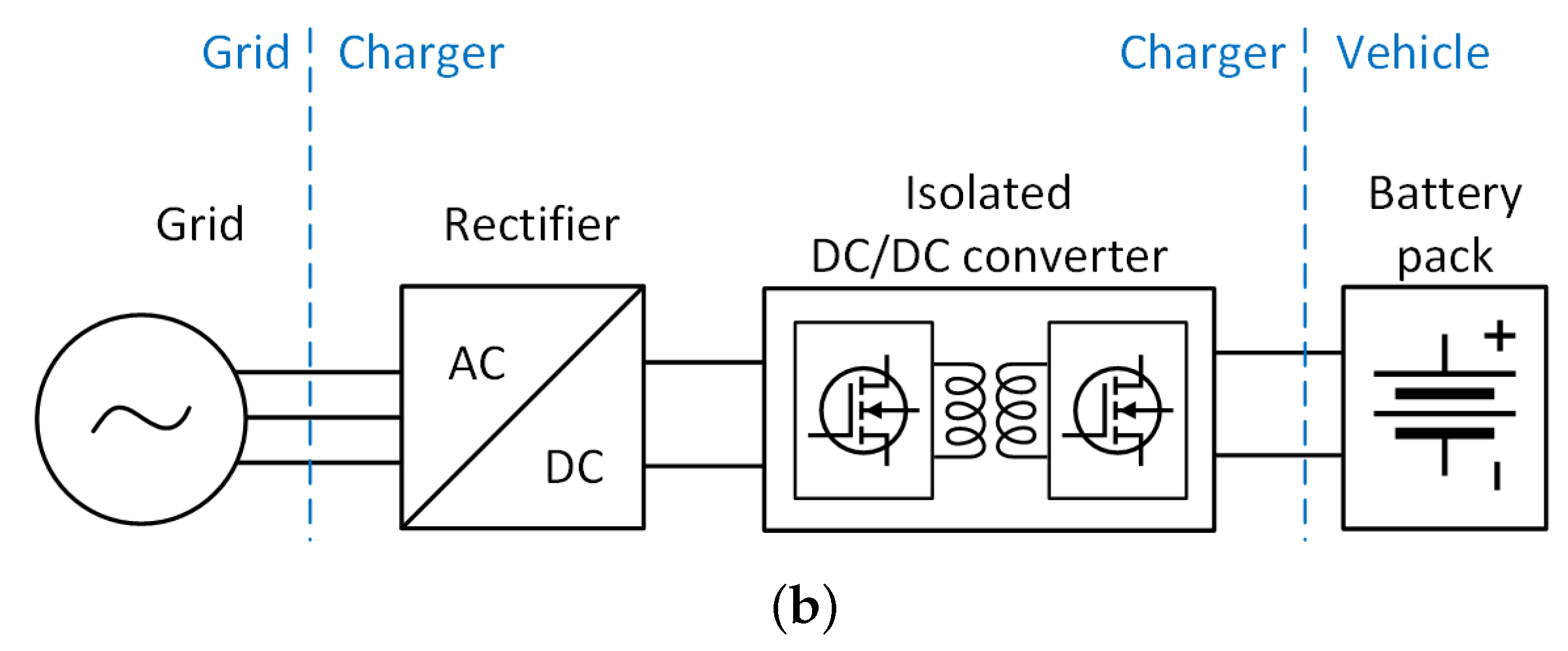
Level 3 DC chargers take power from the three-phase grid. The charger consists of several stages, as shown in Figure 2. Figure 2a shows the diagram of an off-board charger with a low-frequency isolation transformer on the grid side, followed by a rectifier and non-isolated DC/DC converter. The interface between the car and the charger is the blue line that separates the DC/DC converter and the battery pack. Alternatively, the charger can be isolated using the high-frequency isolation transformer within the DC/DC converter, as shown in Figure 2b. The purpose of the DC/DC converter is to control the voltage, and the current applied to the EV battery according to the chosen charging strategy. The most commonly used strategies are current-constant voltage (CC-CV) and pulse charging methodology [7]. The purpose of the rectifier is to deliver the requested power to the DC/DC converter while maintaining the DC link voltage and minimizing grid disturbance.
Given the increasing interest in fast chargers, there has been a number of papers that study different aspects of the charger. A comprehensive review of different fast charger topologies and control systems is presented in [8]. However, it does not study how the choice of a certain architecture or control system impacts the performance of the system or its lifetime. This two-part paper [9,10] focuses on a very detailed review and classification of three-phase rectifier topologies for power factor correction in various applications. However, these papers do not study the architectures specifically for fast-charging voltage levels (>650 V), power levels (>(22 kW)), load profile (10–100% load), and the switching frequency range. Each architecture will present different sets of advantages and disadvantages based on the application. A review of various control strategies for grid-tied inverters in [11] can be applied to chargers with some adjustments. Digital control techniques for Voltage Source inverters (VSI) have been covered in [12]. A quantitative comparison of some of the most common control techniques for VSI in adjustable speed drives application has been presented in [13] and can partially be applied to charger AFE rectifiers. In this paper, the focus is specifically on control systems for fast-charging applications, highlighting the performance of each control system and whether or not they are suitable for modularization.
This paper presents a comprehensive review of AFE rectifiers used in off-board fast charging applications. On top of the regular topics, such as different converter topologies and control approaches, this paper expands further to address other challenges of the off-board chargers that appear with the high-power levels associated with fast charging:
  • Component availability—at high-power levels, the choice of components will become more limited and possibly more costly;
  • Grid impact—increasing power and number of fast chargers introduces more harmonic distortion to the grid, damaging sensitive equipment;
  • Thermal management—cooling systems will become more complex if they need to dissipate power in the range of tens of kilowatts;
  • Reliability—in fast chargers, components are subjected to more stress due to higher power. Moreover, commercial off-board chargers will be cycled more compared to personal on-board chargers, which may lead to a shorter lifetime.
Section 2 compares different topologies for a three-phase rectifier. Section 3 discusses the individual components of the selected AFE topology. Section 4 reviews some of the main control strategies for the AFE rectifier and compares their performance. Section 5 covers the modularization of AFE rectifiers to better suit the fast charging application and presents control systems for a system of parallel converters. Section 6 summarizes cooling techniques for AFE rectifiers in off-board EV charging applications. Section 7 studies the reliability aspect of AFE rectifiers. Section 8 presents the latest tendencies and future outlooks in AFE rectifiers in EV fast charging applications.

2. Comparison of AFE Topologies

The overview of three-phase rectifier topologies adapted from [9,10] is given in Figure 3. The unidirectional rectifiers only support drawing power from the grid to charge the EV battery. Examples of unidirectional rectifiers include simple diode bridge rectifiers, Vienna rectifiers, Swiss rectifiers, and other well-established topologies. The bidirectional rectifiers can feed power from the vehicle back to the grid when necessary. The V2G operation has been proven beneficial in lower-power chargers, while its use in high-power chargers is relatively new. Level 3 bidirectional AFE rectifiers with V2G capabilities are used in DC fast charging stations with renewable energy sources and energy storage systems to offset the effect of the fast chargers on the grid and to provide additional grid services [14,15]. Within bidirectional rectifiers, there are two types: boost-type and buck-type. The boost-type rectifiers have higher DC link voltage compared to the AC side voltage, while it is the opposite for the buck-type. The higher DC link voltage means less current for the same power level, which can be beneficial, especially for high-power systems. As mentioned in Table 1, the next-generation chargers will be operating at 800 V and above. Therefore, in this paper, three-phase, boost-type bidirectional topologies are considered.
The topology of the high-power rectifier has to be selected based on several criteria:
  • Three-phase boost-type rectifier topology suitable for Level 3 DC fast charging or ultra-fast charging;
  • Injects minimal THD to the grid;
  • Bidirectionality is advantageous since it enables a V2G operation;
  • Smaller number of components is advantageous for system reliability and cost.
In this section, a three-phase passive rectifier with an inductive filter on the AC side and a capacitive filter on the DC side is presented as a benchmark. Then some of the most common three-phase bidirectional boost-type rectifier topologies are compared with each other and the benchmark. The selected topologies are highlighted in blue in Figure 3.

2.1. Three-Phase Passive Rectifier

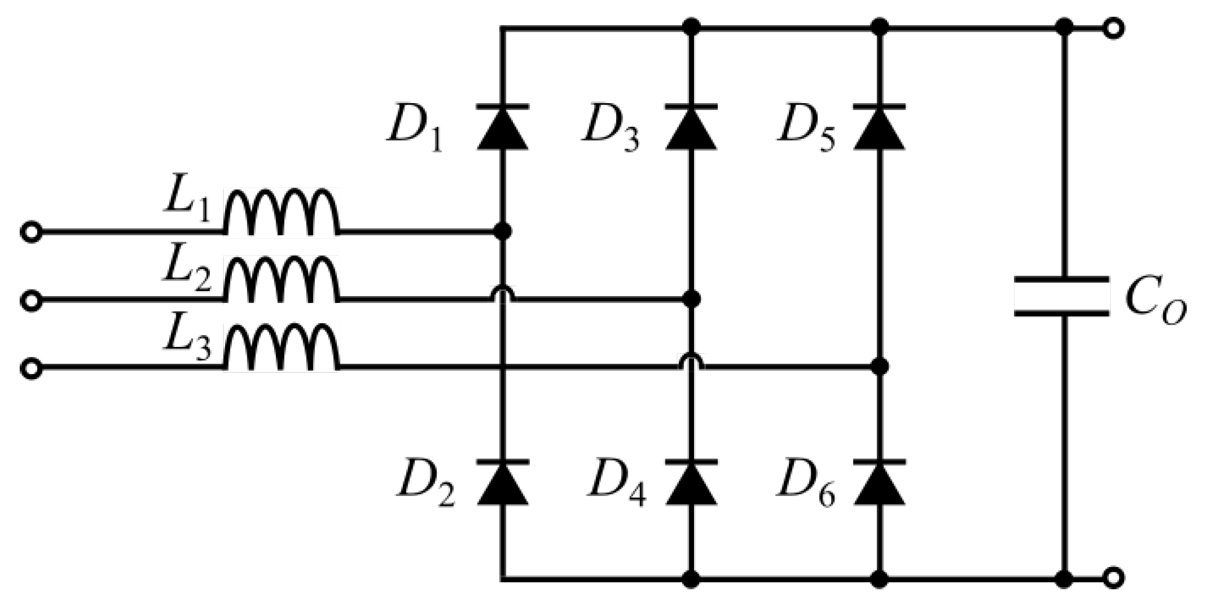
The three-phase diode rectifier is the simplest rectifier topology. It contains only the six diodes, AC side inductors, and the DC side capacitor, as shown in Figure 4.
Since it does not employ any active switches, this converter does not require a control system or gate drivers, which simplifies its operation. The diodes switch at grid frequency, and there is no active current shaping and no control over the output voltage. The diode rectifiers can inject a Total Harmonic Distortion (THD) of 40–70% into the grid currents, and large numbers of fast high-power passive rectifiers would cause stress on the grid [16]. This type of conventional passive rectifier topology is not recommended in fast charging applications due to its lower efficiency, unidirectional power flow, and higher THD.
The operation of the passive rectifier has been simulated in a MATLAB (R2021a, MathWorks, Natick, MA, USA) Simulink environment.For this simulation, the DC side capacitive filter is designed for a 1% voltage ripple on the DC link. The AC side smoothing inductor is designed for an impedance ratio of 0.05, the lower end of the acceptable 0.05–0.15 range [9]. Figure 5 shows the grid side current of the passive rectifier and its harmonic analysis. The current is not sinusoidal and has high amplitudes of lower order (5th, 7th, 11th, and 13th) harmonics.
Figure 6 shows the DC link voltage of the passive rectifier and its harmonic analysis. The DC link voltage is not controlled and settles around 505.5 V for the given load of 30 kW. The peak-to-peak value of the voltage ripple is 5.14 V, close to 1% of the DC link voltage, which is in line with the design expectations. As shown in Figure 6b, the main voltage ripple harmonic appears at 300 Hz with an amplitude of 2.5 V.
With the passive rectifier topology, the DC link voltage is not controlled. Moreover, the grid side currents with dominant low-frequency harmonics result in a THD of 30.9% and a power factor of 0.87. In contrast, if active rectifiers are used, the desired voltage level can be maintained with varying loads, and the THD can be kept minimal while achieving high efficiency and power factor. In the following part, the following boost-type bidirectional active converters are compared:
  • Three-phase two-level six-switch boost-type rectifier;
  • Three-phase three-level neutral point clamped converter;
  • Three-phase three-level T-type converter.
To compare the AFE topologies, they have been designed for similar conditions and simulated. The active rectifiers are designed for 1% ripple on the DC link and 5% THD of grid currents at full load. All three active converters switch at 20 kHz and are rated for 30 kW. The DC link voltage setpoint is 700 V.

2.2. Three-Phase Two-Level Six-Switch Boost-Type Rectifier

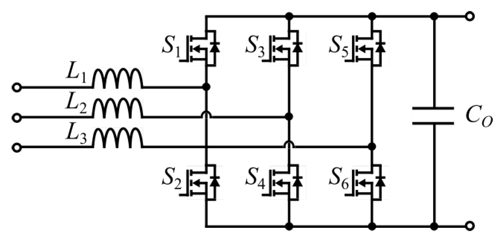
The topology for the three-phase two-level boost-type rectifier is shown in Figure 7. It consists of six active switches, AC side boost inductors, and a DC side filter capacitor. The topology of the boost-type two-level rectifier is simple, robust, and well-known. This topology can be built using commercial H-bridges. The two-level six-switch rectifier topology requires larger volume input inductors and has a limited maximum switching frequency [10] compared to the three-level converters. The lower boundary of the DC link voltage has to be limited due to the boosting nature of the rectifier. For example, if the rectifier is connected to the three-phase grid with 400 V RMS line-to-line voltage, then the minimum DC link voltage will be 565 V, equal to the line-to-line voltage amplitude. Ideally, it should be at least 15–20% higher to reduce the distortion in current waveforms.
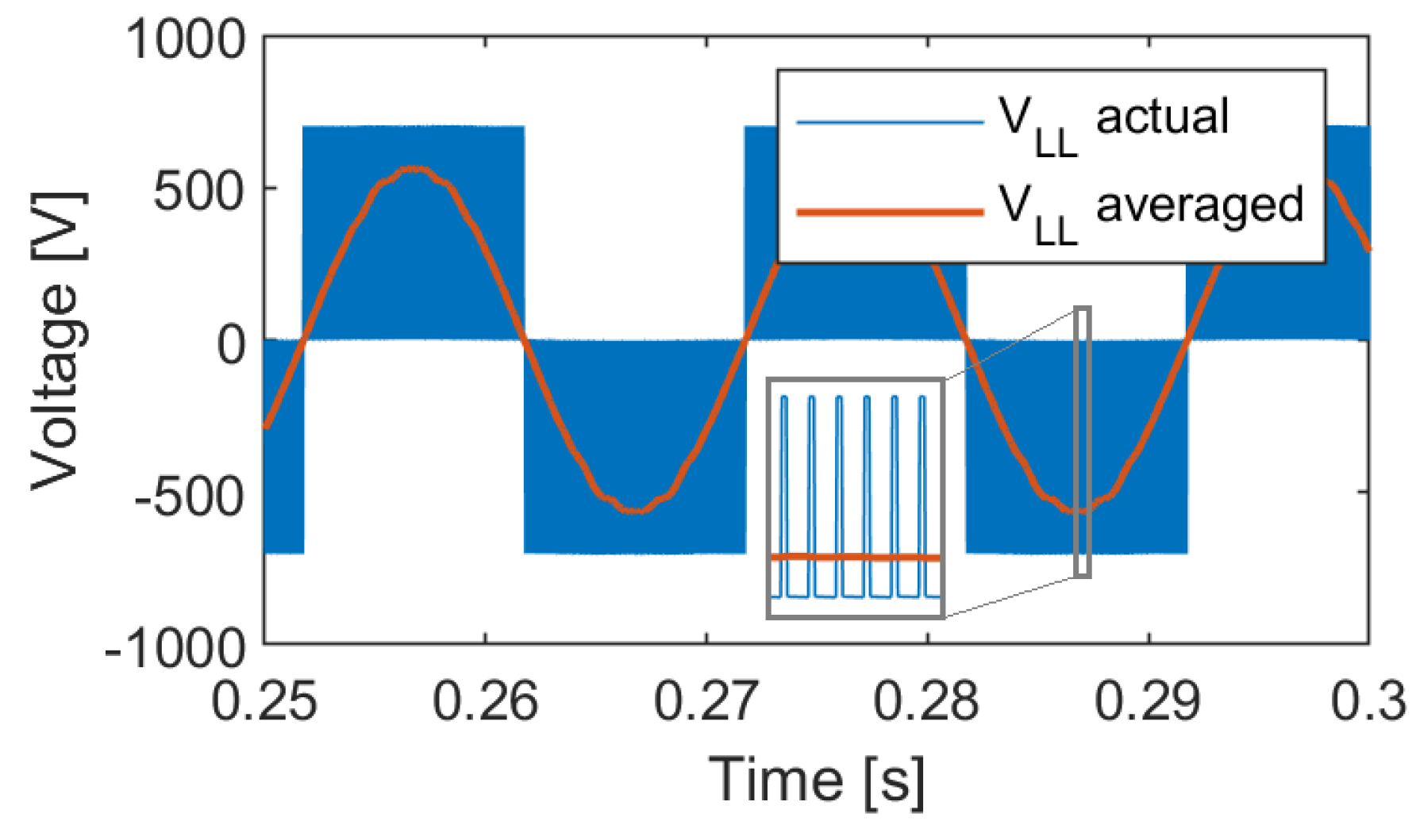
In a two-level topology line-to-neutral rectifier, the voltage is either zero or equal to the DC link voltage. This creates a three-level line-to-line voltage, as shown in Figure 8.
Figure 9 shows the grid side current of the two-level six-switch rectifier and its harmonic analysis. The current is sinusoidal and has harmonics around the switching frequency and its multiples.
Figure 10 shows the DC link voltage of the Two-level six-switch boost-type rectifier and its harmonic analysis. The DC link voltage is controlled to be 700 V at a 30 kW load. The peak-to-peak value of the voltage ripple ranges from 3 to 7 V. As shown in Figure 10b, the voltage ripple harmonics appear around the switching frequency and its multiples. Moreover, a small harmonic component appears at the grid frequency and its multiples.
The two-level six-switch boost-type rectifier results in a well-controlled 700 V voltage at the output with under 1% ripple, and the THD of grid side currents is 4.5% at full load, while the power factor is 0.997. The efficiency of the converter is 98.5%.

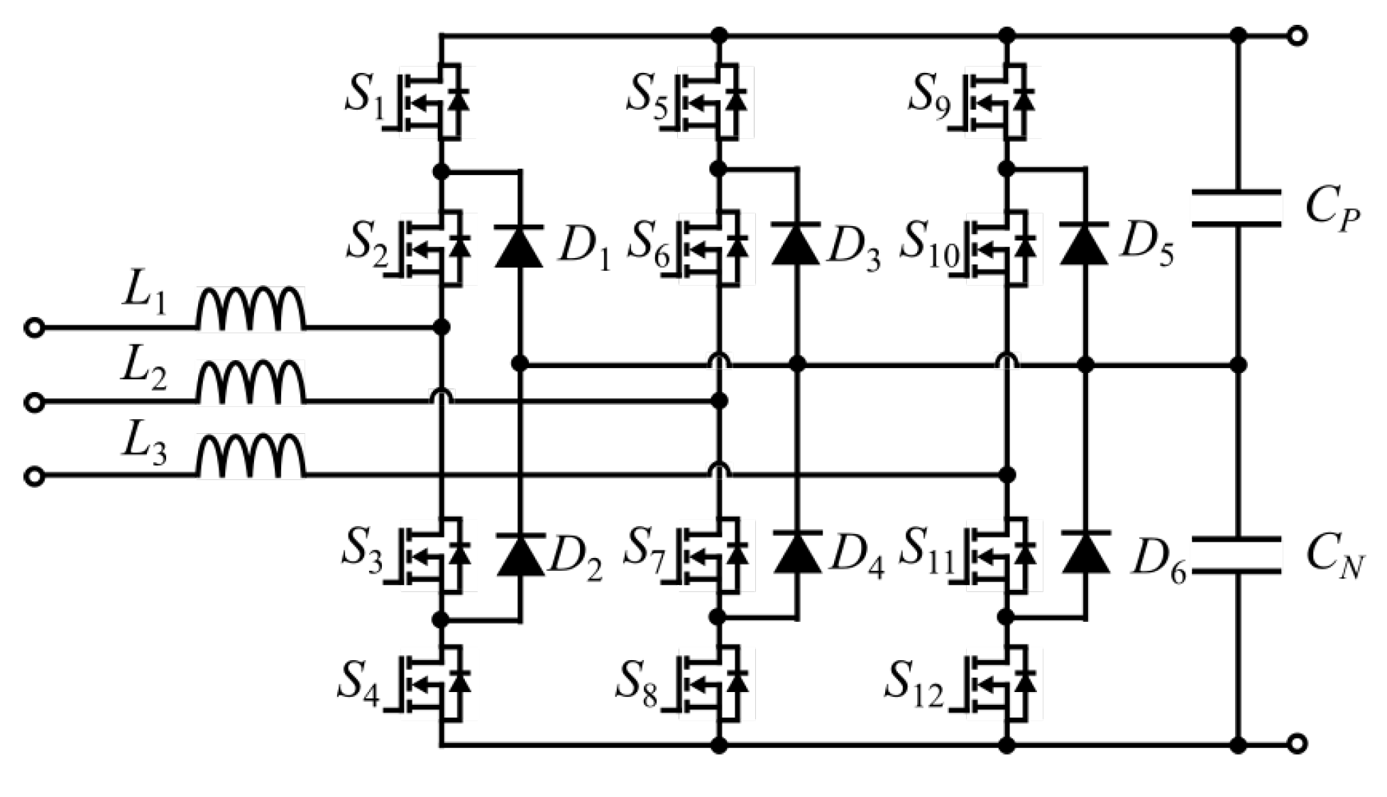
2.3. Three-Phase Three-Level Neutral Point Clamped Converter

The topology of a three-phase three-level neutral point clamped (NPC) converter is shown in Figure 11. It is a three-level topology consisting of twelve active switches, six diodes, and filters. Compared to the two-level converter, switches in this topology see reduced voltage stress and lower switching losses. Moreover, the passive filter size is smaller. However, the component count increases, negatively affecting system reliability, complexity, and implementation effort.
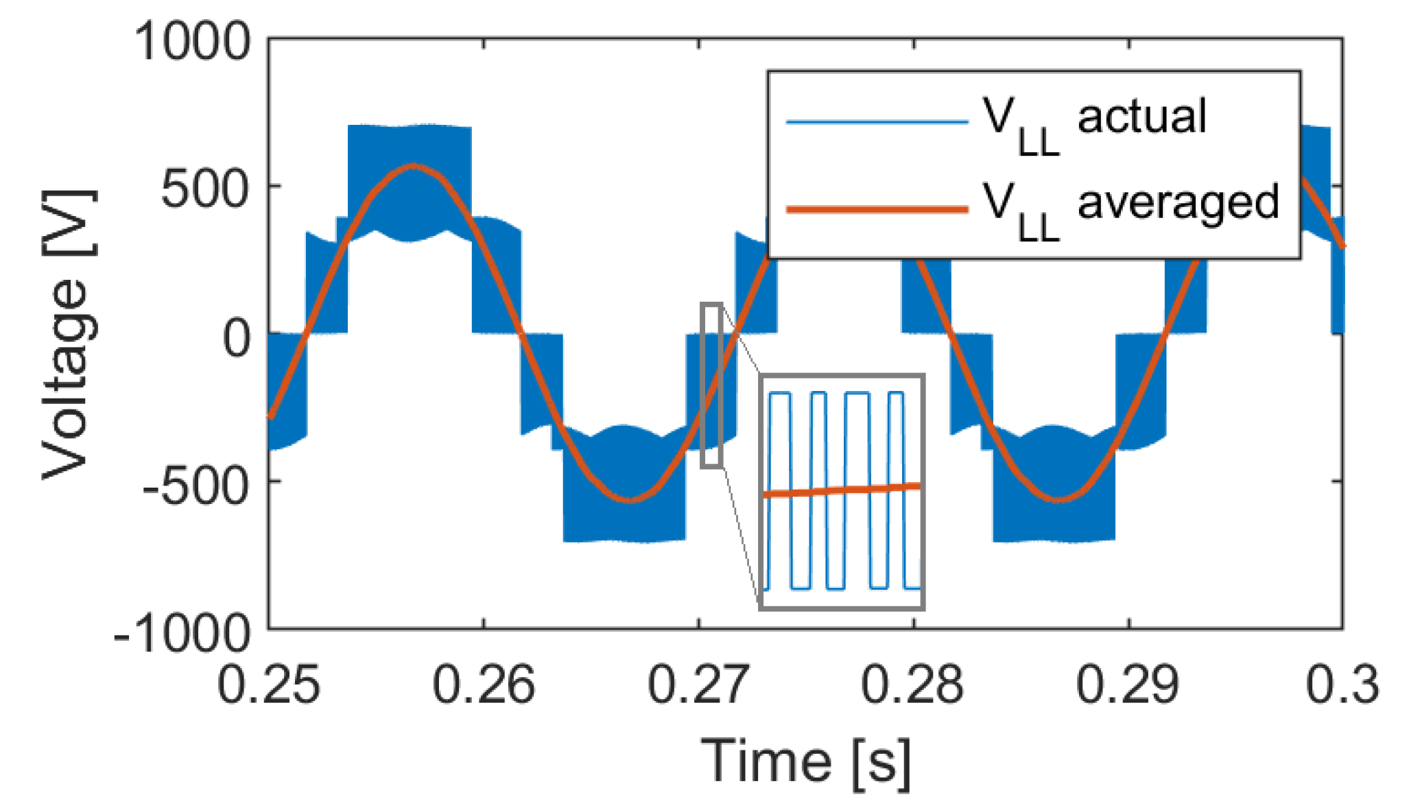
In a three-level topology, the line-to-neutral voltage can be 0.5 V D C , zero, or −0.5 V D C , which creates a five-level line-to-line voltage, as shown in Figure 12.
Figure 13 shows the grid side current of the NPC rectifier and its harmonic analysis. Similar to the two-level topology, the current is sinusoidal and has harmonics around the switching frequency and its multiples. However, there is also a noticeable harmonic at 250 Hz.
Figure 14 shows the DC link voltage of the NPC rectifier and its harmonic analysis. The DC link voltage follows the setpoint. The shape of the DC link ripple has distinct lower frequency harmonics at 300 Hz in addition to the switching frequency harmonics, as shown in Figure 14b.
The NPC converter follows the DC link voltage setpoint. The DC link voltage ripple is 1%, and the grid side current THD is 5% at full load as designed. The power factor is 0.997, and the efficiency of the converter is 98.2% at full load. The main drawback of the NPC topology is that it uses 12 active and 6 passive switches, which makes it costly and complex. However, it significantly reduces the inductor size (44% reduction in this case), and the switches are all subjected to only half the DC link voltage. This topology requires two capacitors in series, which leads to higher capacitance values and lower capacitor voltage ratings.

2.4. Three-Phase Three-Level T-Type Converter

Three-phase three-level T-type converter is a bidirectional variation of the three-phase Vienna rectifier. The topology is shown in Figure 15 [10,17]. This rectifier uses 12 active switches, compared to the original unidirectional topology that uses 6 diodes and 6 active switches [9]. Moreover, it has three boost inductors on the AC side and a split capacitor on the DC side. This is a three-level topology similar to NPC. However, it has lower semiconductor losses for low switching frequencies compared to NPC, and it can be implemented using standard six-pack modules. This topology uses switches for two different voltage ratings.
The three-level T-type rectifier also generates a three-level line-to-neutral voltage and five-level line-to-line voltage, as shown in Figure 16.
Figure 17 shows the grid side current of the T-type rectifier and its harmonic analysis. The current is quite similar to the NPC converter current, as it also contains a harmonic at 250 Hz.
Figure 18 shows the DC link voltage of the T-type rectifier and its harmonic analysis. The DC link voltage is centered at the setpoint, and the main ripple harmonic is at 300 Hz, as shown in Figure 18b.
The three-phase three-level T-type rectifier uses similar filter sizes and filter ratings as the NPC. The main difference is the number and rating of the switches. The two switches between positive and negative DC link block voltages between 0.5 V D C and V D C , so they have to be rated for V D C . However, when these devices are switching, the voltage level changes between zero and 0.5 V D C , which results in lower switching losses compared to switching with full V D C . The devices connected between the phase leg midpoint and DC link midpoint block 0.5 V D C , so they only need to be rated for 0.5 V D C . Moreover, they also switch between zero and 0.5 V D C . Overall, the reduced number of components compared to NPC, while maintaining switching from 0.5 V D C , results in higher efficiency than NPC. The efficiency of the T-type rectifier at full load is 98.95%.

2.5. Comparison of Rectifier Topologies

A comparison of different AFE topologies and the passive rectifier performances at full load is presented in Table 2. To perform a quantitative comparison of the rectifier topologies, they have been simulated in MATLAB Simulink. Each rectifier is designed for 30 kW using SiC devices. The output voltage of the passive rectifier cannot be controlled. Therefore, it differs from the active rectifier output voltage, which is 700 V. The active rectifiers switch at 20 kHz. The filters are designed for 1% voltage ripple at the DC link and 5% THD of the grid side currents at full load. The required AC side inductance is twice smaller for three-level topologies for the same level of current ripple. The DC link capacitance is higher for three-level topologies due to the series connection. However, the voltage rating for the capacitor is lower for NPC and T-Type. The switches on the three-level topologies are subjected to less stress, which increases the lifetime of individual switches. However, the higher component number in three-level topologies negatively affects the overall converter reliability. The control of the three-level topologies can be as simple as two-level topologies, with modifications to the modulation scheme. However, three-level topologies may require balancing between the series capacitances, which can complicate the control system. The higher number of components increases the cost of three-level topologies compared to the two-level.
At 20 kHz switching frequency, the T-type rectifier shows the highest efficiency (98.95%), with a two-level rectifier in second place (98.5%) and NPC in third place (98.2%). This is in line with the behavior reported in [18]. At the lowest switching frequency, the efficiency from high to low is T-type, two-level, and then NPC. For insulated-gate bipolar transistor (IGBT) modules used in [18], that behavior continues until approximately 8 kHz. Since we are using SiC devices, that cutoff occurs at a higher frequency of approximately 35 kHz, as shown in Figure 19. When the switching frequency increases, the efficiency of the two-level rectifier decreases much more rapidly compared to three-level topologies. The efficiency of NPC decreases the least with the increase in frequency. Therefore, after a certain high frequency (36 kHz for IGBT modules in [18]), NPC will be the most efficient topology. Using Silicon Carbide (SiC) devices, this behavior does not appear until 200 kHz, as shown in Figure 19.

3. Components of AFE Rectifiers

All three active bidirectional three-phase rectifiers presented in the previous section consist of similar building block components, even though their exact characteristics might differ. Rectifiers consist of a number of active switches, optional diodes, AC side filters, and DC side filters. The AC side filter can range from a simple inductor (L filter) to higher-order LCL-LC filters [19,20]. The DC side filter is usually a DC link capacitor [6], or several of them connected in series or parallel. In the following subsections, each of the components of the AFE rectifier is discussed in more detail.

3.1. Power Semiconductor Selection

Switches comprise the main part of the AFE rectifier. The efficiency and reliability of these switching components are crucial for the performance of the entire AFE system [6]. With the emergence of new and improved devices, such as Wide Band-Gap (WBG) semiconductor switches, the AFE rectifier performance can be improved substantially [21,22,23]. The WBG devices can withstand higher junction temperatures, block higher voltages, and operate under higher switching frequencies. Moreover, switching and conduction losses are lower in WBG devices [24]. WBG active switches allow higher power density in the weight and volume constraints of the on-board charger while allowing off-board chargers to operate at even higher power levels. The efficiency of WBG chargers is reaching as high as 98.5% [25,26].
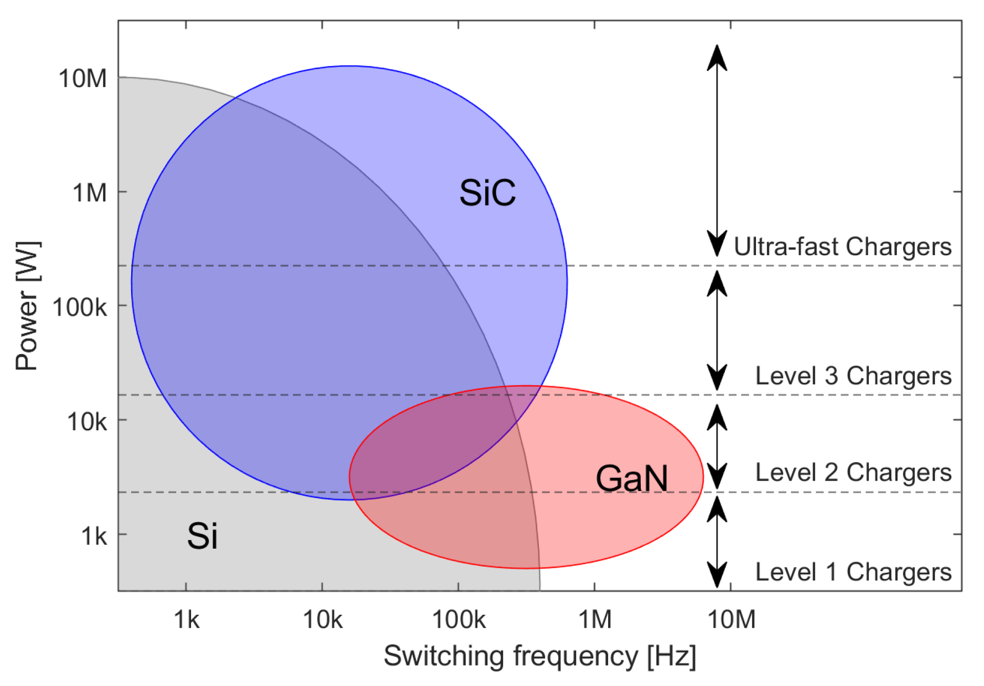
Nowadays, Silicon carbide (SiC) and Gallium Nitride (GaN) are the types of WBG devices commonly used in EVs. Silicon (Si), SiC, and GaN semiconductor materials have fundamental differences in their material properties, such as bandgap, critical field, carrier mobility, electron saturation velocity, and thermal conductivity [27], which makes them suitable for different applications. As shown in Figure 20, Si is still the mainstream technology. For higher power and frequency applications, SiC devices are used. GaN devices are used in higher frequency but lower-power applications [28]. The Level 3 and the ultra-fast off-board chargers are outside the power level that GaN can support at this time. Therefore, Si and SiC are suitable choices for the design of high-power off-board chargers. The Si IGBTs tend to have higher power ratings compared to metal–oxide–semiconductor field-effect transistors (MOSFETs). However, they are much slower, meaning they cannot operate at higher switching frequencies. Higher switching frequencies are essential in decreasing filter component sizes. Moreover, the SiC devices can block voltages above 10 kV [29], which makes them a suitable choice for DC fast chargers connected to the medium voltage grid. A 350 kW SiC-based DC charger at 4.16 kV AC is presented in [30]. While [31] proposes a SiC-based fast charger connecting to a 2.4 kV AC. The current ratings of commercially available discreet SiC devices can reach up to 100 A for SiC Diodes and MOSFETs and 160 A for SiC Bipolar Junction Transistors (BJTs) [29]. SiC power modules that consist of several devices in parallel can be used for higher current applications.

3.2. DC Link Capacitor Selection

DC link capacitors are one of the main components of power electronic converters. There are three main types of capacitors used in automotive applications: Aluminum Electrolytic Capacitors, Metallized Polypropylene Film (MPPF) Capacitors, and high-capacitance Multi-Layer Ceramic (MLC) Capacitors [32]. Electrolytic capacitors are more cost-effective and have the highest energy density and capacitance. Typically, the required capacitance values for AFE DC link capacitors in fast charging applications are not high, especially if compared to the capacitors in single-phase chargers. However, the current rating of these capacitors has to keep up with the high-power rating of the fast chargers. MLC capacitors have better reliability and can perform under higher temperatures and frequencies [32]. Operating at higher switching frequencies allows the use of smaller filter components and minimizes the grid disturbance of the fast charger. Since fast charger components are expected to perform in very harsh conditions, increased reliability is very important. The MPPF capacitors have moderate performance and cost. However, they are limited by their reliability and operating temperature [32].
The DC link capacitance C D C is sized, taking into account the DC current I D C , DC link voltage V D C , switching frequency f s w , and the desired voltage ripple [6]. The capacitor size can be decreased by increasing the switching frequency or allowing a higher ripple. The higher value of capacitance decreases the ripple. However, a higher value of capacitance will negatively impact the system dynamics. In order to obtain the same rate of change in the DC link voltage for a higher capacitance DC link, a higher current is necessary.
To conclude, a combination of electrolytic and MLC capacitors would be the most cost-effective approach, while using only MLCC would increase system reliability.

3.3. Grid Side Filters Selection

The switching converters introduce harmonic currents into the grid. IEEE 519-2014 sets the limits on voltage and current harmonics at the point of common coupling (PCC) [33]. The IEEE 519-2014 states the limit on the individual current harmonics and the total demand distortion (TDD). TDD is the ratio of the root mean square (RMS) of the harmonic content to the maximum demand current. It is important to differentiate between the current THD (THDi) and TDD. THDi uses instantaneous fundamental current as a base, not the maximum demand current. These TDD and THDi values will be equal only when the load is 100%.
To avoid damage to other sensitive equipment connected to the grid, the harmonics should be reduced at the source. This can be achieved using passive filters, active filtering techniques, or other advanced control approaches [34]. The control techniques to reduce the harmonics will be discussed in Section 4 and Section 5. This subsection discusses passive filters as a way to reduce the amplitude of unfavorable harmonics. The level of attenuation depends on several factors, including the size and topology of the filters, the amplitude, and the frequency of current harmonics. The filters should be designed to reduce harmonics until the converter complies with the specifications given in the applicable standard.
In AFE rectifiers, there is a filter on each phase of the converter at the grid side. There are three common types of filter topologies used for the grid-connected VSC: L, LC, and LCL [20]. However, higher-order filters, such as LLCL and LCL-LC, are used too [19]. There is a trade-off between the attenuation level, filter complexity, cost, and control system complexity when considering the topology of the filter. Moreover, with the increased number of components in the filter, the power losses on those components might increase.

3.3.1. L Filter

The L filter is a first-order filter, and it can obtain −20 dB attenuation [19]. It is simple, easy to design, and effective in suppressing PWM harmonics in converters with high switching frequencies. However, the inductance value required to reach the desired harmonic levels might be very high. In high-power applications, the high-inductance L filters might result in increased size and cost [19]. Moreover, the value of inductance limits the operating range of the converter. The minimum allowed DC link voltage value starts from the peak line-to-line voltage for zero inductance and increases with the inductance of the filter [35,36].

3.3.2. LC Filter

The LC filter is a second-order filter and it can obtain −40 dB attenuation. It consists of an inductor on each phase on the inverter side and a capacitor parallel to the grid. Due to the presence of the capacitor, the inductance value can be smaller [37]. However, the capacitance value required to obtain the desired cutoff frequency can be too high and affect the system’s dynamic response. Moreover, the resonant frequency of the LC filter is dependent on the grid impedance [38]. The LCL filters can provide a better decoupling from the grid impedance [38].

3.3.3. LCL Filter

The LCL filter is a third-order filter, and can obtain attenuation of 60 dB per decade for frequencies above resonant frequency [19]. It consists of a series inductor on the inverter side, a parallel capacitor, and another series inductor on the grid side. Moreover, in order to suppress the resonance peak, a damping resistor is added in series to the capacitor [20]. Good attenuation throughout different load operations can be achieved using an LCL filter without excessive size or cost. It is worth noting that in the LCL filter, the grid side inductor is subjected to less harmonic current stress than the inverter-side inductor [38].

3.3.4. Comparison of Filter Topologies

Figure 21 presents the simulation results of a two-level 30 kW AFE rectifier with different filters operating at 20 kHz switching frequency. The blue line in Figure 21a represents the individual harmonic limit from IEEE 519-2014 [39]. The standard states limits for up to the 50th harmonic, while the main harmonics for this type of AFE appear around the switching frequency near the 400th harmonic. Harmonics of the higher order can be taken into account in THD/TDD calculations, as shown in Figure 21b. For the L-type filter, the THD starts at 48.6% for 10% load and lowers down to 5% for 100% load. While the TDD stays consistently under the 5% limit specified in IEEE 519-2014. The LC-filter has slightly lower THD at lower loads compared to the L-filter. The THD of grid side currents for LCL-filter changes from 39% to 5% when the load changes from 10% to 100%.
Figure 22 shows how the estimated cost and weight of different filter topologies change over a range of power ratings. Generally, LCL filters tend to have a 15–25% higher cost and 5–10% higher weight than other topologies. This increase may be justified, given the superior performance of LCL filters.

3.3.5. Filter Inductor Component Selection

Regardless of the chosen filter topology, the design of the inductor for AFE in fast charger applications is challenging due to the combination of high current and high frequency. The inductors in this application are subjected to the current with fundamental harmonics at grid frequency and current ripple at the switching frequency. The main components of an inductor are the core and the windings.
The wire for the winding should be selected based on the skin depth that is calculated from the switching frequency. Litz wires with a strand radius that does not exceed the skin depth are a common solution. The total conducting area of the wires should be selected based on the RMS current density measured in amperes per square millimeter. For a natural air-cooled system, the current density is selected to be under 3 A/mm 2 . For fast-charging applications, additional cooling systems might be necessary to obtain a reasonable final area for the conductor. A current density greater than 10 A/mm 2 can be selected if a liquid cooling system is used [40].
For core selection, the main parameters are the energy stored in the inductor, as well as flux density and core losses. With the increase in the operating current rating, the numeric value of the inductance will decrease, while the energy stored in the inductance increases due to the high current. A comparison of magnetic core material types suitable for the application is given in [41].

4. Control of a Single AFE

There are a number of well-established and widely used control strategies for AFE rectifiers. Figure 23 summarizes the existing control techniques [8,11,42]. Some of the well-established and widely used control strategies for AFE rectifiers are highlighted in blue in Figure 23 and will be further discussed in this section:
  • Voltage Oriented Control (VOC) is a type of Linear Control with PI controllers.
  • Direct Power Control (DPC) is classified under Non-linear Hysteresis Control since active and reactive power is controlled using a hysteresis controller with a lookup table.
  • Optimal switching vector Model Predictive Control (MPC) is classified under Predictive Control.
  • Hysteresis Current Control (HCC) is a type of Non-linear Hysteresis Control applied directly to phase currents.
Some of these control techniques are better suited for maintaining the DC bus voltage, while others allow decoupled control of active and reactive power flow. They also vary in the number and types of required sensors, and the complexity of calculations. In this section, first, grid synchronization is discussed, then VOC, DPC, MPC, and HCC are described and compared. Moreover, the performance of the aforementioned control systems is compared in a simulation using a high-fidelity electro-thermal model of the two-level six-switch boost-type AFE rectifiers in terms of disturbance rejection, THD, efficiency, thermal behavior, etc.

4.1. Grid Synchronization

Some of the control systems described in the following subsections are implemented in the synchronous reference frame, meaning that they require a series of Clarke–Park and inverse Clarke–Park transformations. The Park transformations rely on the angle of the three-phase voltage vector [43]. This angle is essential to ensure that the voltage of the grid-connected converter is synchronized with the grid voltages [44,45].
Phase Locked Loop (PLL) has been used since 1930 for radio synchronization, and its applications have expanded since [45]. Figure 24 shows the basic synchronous reference frame (SRF) PLL that consists of several stages. First, the voltages in three-phase are converted to the α β domain using Clarke’s transformation. Then, from α β to d q 0 using an estimated angle θ ^ for Park’s transformation. This is the Phase Detector (PD) stage of the PLL [45]. The q-axis component of the voltage is then passed through the PI controller, acting as a Loop Filter (LF) to obtain the estimated frequency. The next stage, Voltage-Controlled Oscillator (VCO), uses this frequency to obtain the estimation of phase angle Θ ^ .
The performance and accuracy of PLL heavily depend on the grid conditions. Therefore, novel methods for robust PLL that can work in unstable or weak grid conditions are being developed [44,46].

4.2. Voltage Oriented Control

The VOC of an AFE rectifier uses cascaded control loops. As shown in Figure 25, the outer control loop controls the DC link voltage using a proportional-integral (PI) controller. The PI’s output represents the DC current required to keep the DC link voltage at the desired level. This DC current can be translated into the respective d-axis current reference i d * using a power balance equation.
The two inner control loops control the direct and quadrature axis currents. In the standard implementation, a PI controller is used for each of these control loops as well.
The corresponding outputs of the d q current PI controllers are denoted as V r d and V r q . They represent the voltage that needs to be applied over the boost inductor to achieve the desired current, i d or i q , as shown in (1).
V r d = L d i d d t + R i d V r q = L d i q d t + R i q
To obtain the desired inverter voltage, V r d and V r q , which can then be transformed into three-phase values and passed on to the modulator, a feed-forward compensation to decouple direct and quadrature axes and the grid voltages, V d and V q , are added, as shown in Equation (2).
V r d = V r d + ω L i q + V d V r q = V r q ω L i d + V q
The VOC requires two AC voltage sensors, three AC current sensors, and one DC voltage sensor. Moreover, the grid voltage angle is used in Clarke–Parke transformations; therefore, a PLL is required.

4.3. Direct Power Control

In Direct Power Control (DPC), the control action is selected from a table of the converter switching states based on the instantaneous difference between the reference and estimated values of active and reactive power [47].
As shown in Figure 26, the outer PI control loop to control the DC link voltage generates a DC current reference, which is further used to calculate the active power reference. The reactive power reference is set to zero for unity power factor operation [48]. The instantaneous active and reactive power is estimated from the grid side measurements. The error between these estimations and the reference values is then passed to the hysteresis comparator, and the results are further used to calculate S p and S q .
If the value of S p or S q is equal to one, it means that the active or reactive power needs to be increased, while zero means it needs to be decreased. The control system uses the values of S p , S q , and the grid voltage angle θ to decide the next switching state using a switching table. For the purposes of this paper, a switching table and corresponding voltage vectors from [49] have been used. The grid voltage angle sector θ n is selected according to Equation (3) below. Therefore, the first sector is between angles −30 and 0 .
( n 2 ) π 6 θ n ( n 1 ) π 6
The DPC requires two AC voltage sensors, three AC current sensors, and one DC voltage sensor. No PLL is required. There are implementations of DPC where the AC voltages are estimated using other measurements, and, therefore, they can omit AC voltage sensors [49].

4.4. Model Predictive Control

Model Predictive Control (MPC) uses the mathematical model of the system to predict the outcome of a control action; it then chooses the action that minimizes the cost function. The cost function represents the difference between the reference and predicted system states.
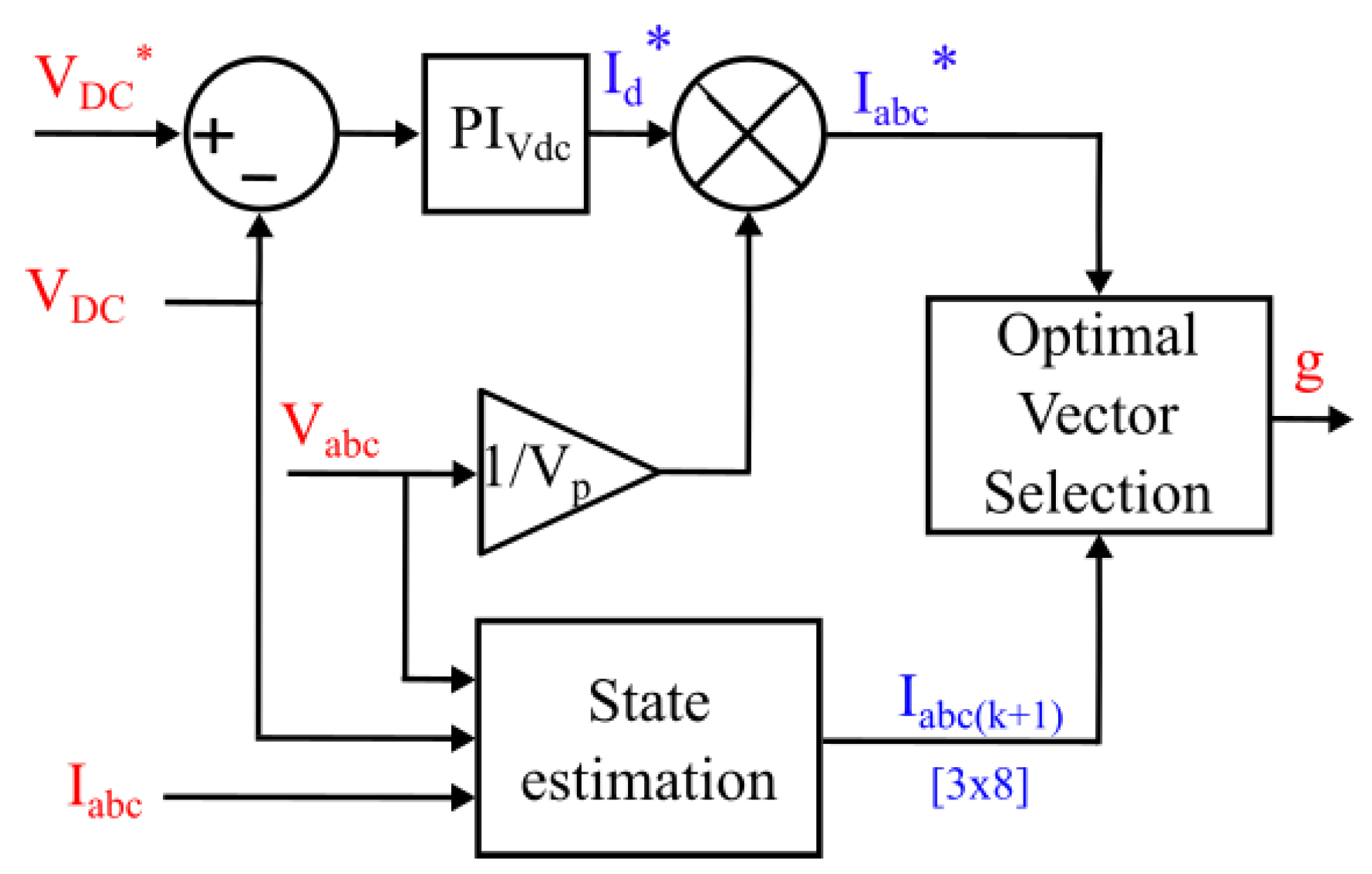
Normally, the MPC is used in the “inner” control loop in combination with an “outer” voltage PI. The MPC controls the active and reactive power or AC currents [50,51,52]. While it is possible to include the control of DC link voltage in the MPC formulation, it would not be accurate unless the load current is compensated for.
If the MPC is implemented in a natural reference frame ( a b c ), as in Figure 27 or a stationary reference frame ( α β ), it does not require PLL. However If the MPC is implemented in a synchronous ( d q ) reference frame, as shown in Figure 28, it requires PLL [52,53,54,55,56].
There are two commonly used types of MPC: Finite Control Set MPC (FCS-MPC) and Continuous Control Set MPC (CCS-MPC) [57].
CCS-MPC generates a continuous control signal, which is then converted to gate signals using modulators [58]. Therefore, in the case of an AFE rectifier, the expected output of the MPC would be the rectifier voltage references in d q , α β , or a b c domains. The advantage of the CCS-MPC is that the converter operates at a constant switching frequency, and a long prediction horizon is possible without special search algorithms due to lower computational cost. However, the formulation of the CCS-MPC strategies is complex [57].
The FCS-MPC applied to AFE rectifiers chooses from a finite set of control actions to minimize the cost function. The two common types of FCS-MPC are the Optimal Switching Vector MPC (OSV-MPC) and the Optimal Switching Sequence MPC (OSS-MPC). The OSV-MPC is the most popular type of MPC used for power electronics applications [57]. For OSV-MPC, the available control actions are the eight possible output voltage vectors that correspond to the eight valid switching states (000, 001, 010, 011, 100, 101, 110, 111) of the AFE rectifier. The OSV-MPC results in a variable switching frequency, which might not be desirable in some cases. OSS-MPC takes care of this problem by using a limited number of switching sequences as a control set, which results in a constant switching frequency. Therefore, both types of FCS-MPC generate gate signals directly and do not require a modulator.
There is no formal way to evaluate the stability of MPC controllers [57]. There are many variations in MPC; therefore, this study is focused on OSV-MPC. OSV-MPC requires two AC voltage sensors, three AC current sensors, and one DC voltage sensor. PLL is optional.

4.5. The Hysteresis Current Control

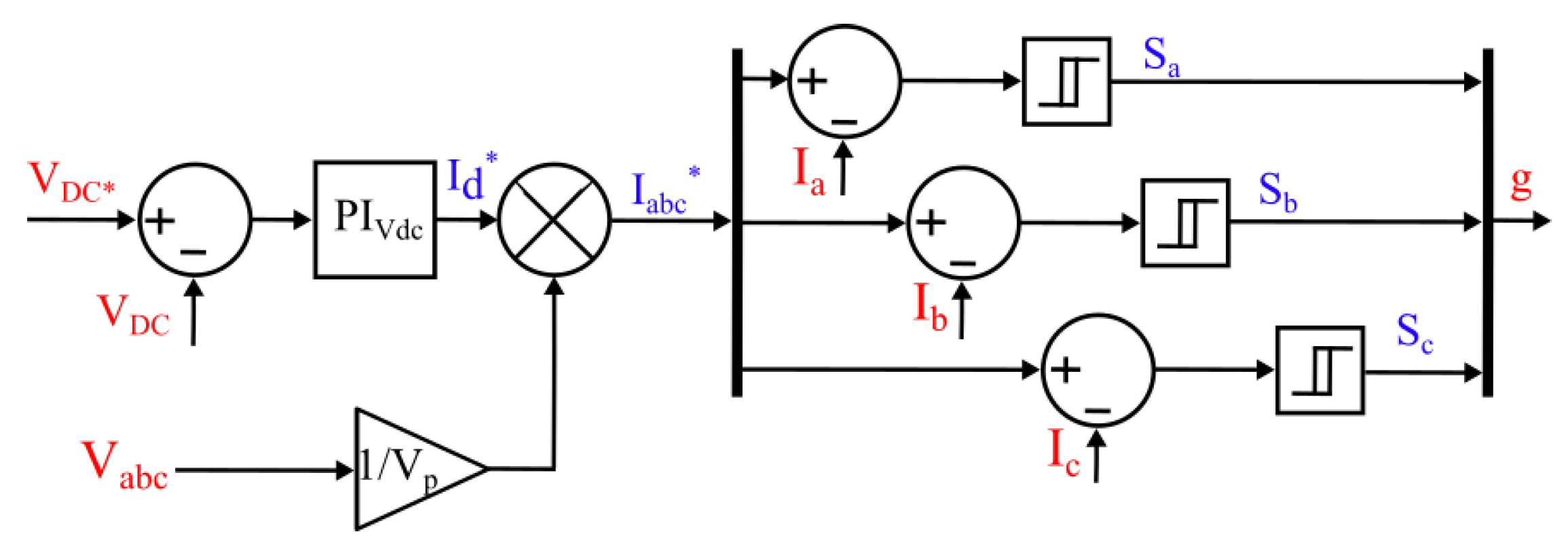
The Hysteresis Current Control (HCC) is used to control the current flowing through the AFE rectifier. The simplest implementation of HCC is shown in Figure 29. The HCC receives a reference for the DC current from the outer control loop. This reference is multiplied by normalized phase voltages to obtain the three-phase sinusoidal reference currents for the current controller.
The current level higher than the reference current by a magnitude of the hysteresis band is called the “upper band”, and the current level lower than the reference current by a magnitude of the hysteresis band is called the “lower band”. If the measured current is above the upper band ( i p h > i p h * + H B ), then the upper switch is on. If the measured current is below the lower band ( i p h < i p h * H B ), then the lower switch is on.
The hysteresis band is the main tunable parameter of the HCC. By decreasing the magnitude of the hysteresis band, ripple can be reduced, while the switching frequency will increase. In the standard implementation, the hysteresis band is constant. However, it can also be sinusoidal or adaptive [59]. The width and type of the hysteresis band define the switching frequency, ripples, and overall efficiency of the system. In the case of constant and sinusoidal hysteresis band HCC, the switching frequency is variable. However, constant switching frequency can be achieved using the adaptive HCC. The variable switching frequency is normally not desired due to the difficulty of filter design and unpredictable noise issues [42].
The standard implementation of HCC requires three AC current sensors, one DC voltage sensor, and two AC voltage sensors and does not use PLL.

4.6. Modulation

The VOC, continuous control set MPC uses Pulse Width Modulation (PWM). While DPC, HCC, and finite control set MPC to generate gate signals directly without the use of a modulator. There are several types of PWM: carrier-based PWM, Space vector PWM, pre-programmed PWM, and closed-loop PWM [58]. Some sources also mention lookup table-based modulation [11]. Carrier-based modulation and space vector modulation are the most commonly used methods.

4.6.1. Carrier-Based PWM

In this method, the sinusoidal modulation signals generated by the controller are compared to the carrier signal. The frequency of this carrier signal defines the converter switching frequency. The carrier signals are usually triangular. The use of carrier-based PWM allows the interleaving of carrier signals between different converters or phases, which might be useful for decreasing ripples in the converter.

4.6.2. Space Vector PWM (SVM)

The SVM calculates the sequence of switching vectors and the corresponding duty ratio to be applied during the sampling period.

4.7. Comparison of Control Strategies

Table 3 summarizes the main features of different control strategies employed for AFE in EV charging applications. Many control strategies vary in implementation; therefore, the most basic version of each control system is used in this evaluation. With the assumption of a balanced grid, the number of AC voltage sensors can be decreased from three to two. Moreover, there are a number of sensorless implementations that rely on a series of assumptions regarding the state of the grid and the accuracy of system models [60]. Overall, the VOC has the advantage of constant switching frequency but requires a modulator. While control in a synchronous reference frame might make it easier to track the reference, it requires PLL, which increases the computational load on the controller. Moreover, a number of hybrid control systems combine different approaches, such as MPC and DPC in [61,62,63].
In order to further compare the performance of various control systems, they have been implemented in a MATLAB Simulink environment. The simulated AFE system consists of six C3M0021120K SiC-MOSFETs, three inductors on the AC side, one capacitor on the DC side, three AC voltage sensors, three current sensors, and one DC voltage sensor. The parameters of the rectifier are given in Table 4. The AC-side filter inductors are designed to keep the grid current THD under 5% at full load and the switching frequency at 20 kHz. A forced air cooling system is used to keep the junction temperature at a reasonable level.
The system is simulated at full load condition, and then a 20% drop in the load is applied. The simulation results are summarized in Table 5. All the control systems are running at 1 μ s sampling time, and the simulation step time is 0.1 μ s. As mentioned earlier, the converter was designed for an AFE with a 20 kHz switching frequency; therefore, the switching frequency for the modulation carrier waveform for VOC has been set to 20 kHz. The operating frequency of HCC is adjusted by changing the hysteresis window. For DPC and OSV-MPC, the sampling time of the inner control loop that selects the gate signals is adjusted to bring the average switching frequency as close to 20 kHz as possible.
The THD of grid currents, efficiency, SiC MOSFET mean junction temperature, and swing is given for full load conditions. Then, the overall time to simulate the full AFE with each control system for one second is given. Next, the disturbance rejection behavior of each control approach is demonstrated in terms of the voltage overshoot and the time it takes to return to the setpoint.
When the control system is engaged in a pre-charged rectifier, it takes up to 25 ms to reach the setpoint. As shown in Figure 30, the DPC is the fastest to reach the setpoint, while the other three perform similarly.
In steady state full load operation, the OSV-MPC demonstrates the highest voltage ripple of 11 V. Generally speaking, the voltage ripple is inversely proportional to their switching frequencies, as shown in Figure 31. Figure 31b shows the harmonic content of the DC link voltage with different control systems. VOC has a fixed switching frequency, so the harmonics around the switching frequency are the most prominent. The DPC, MPC, and HCC have higher harmonic content on average, but it is distributed throughout the range of frequencies.
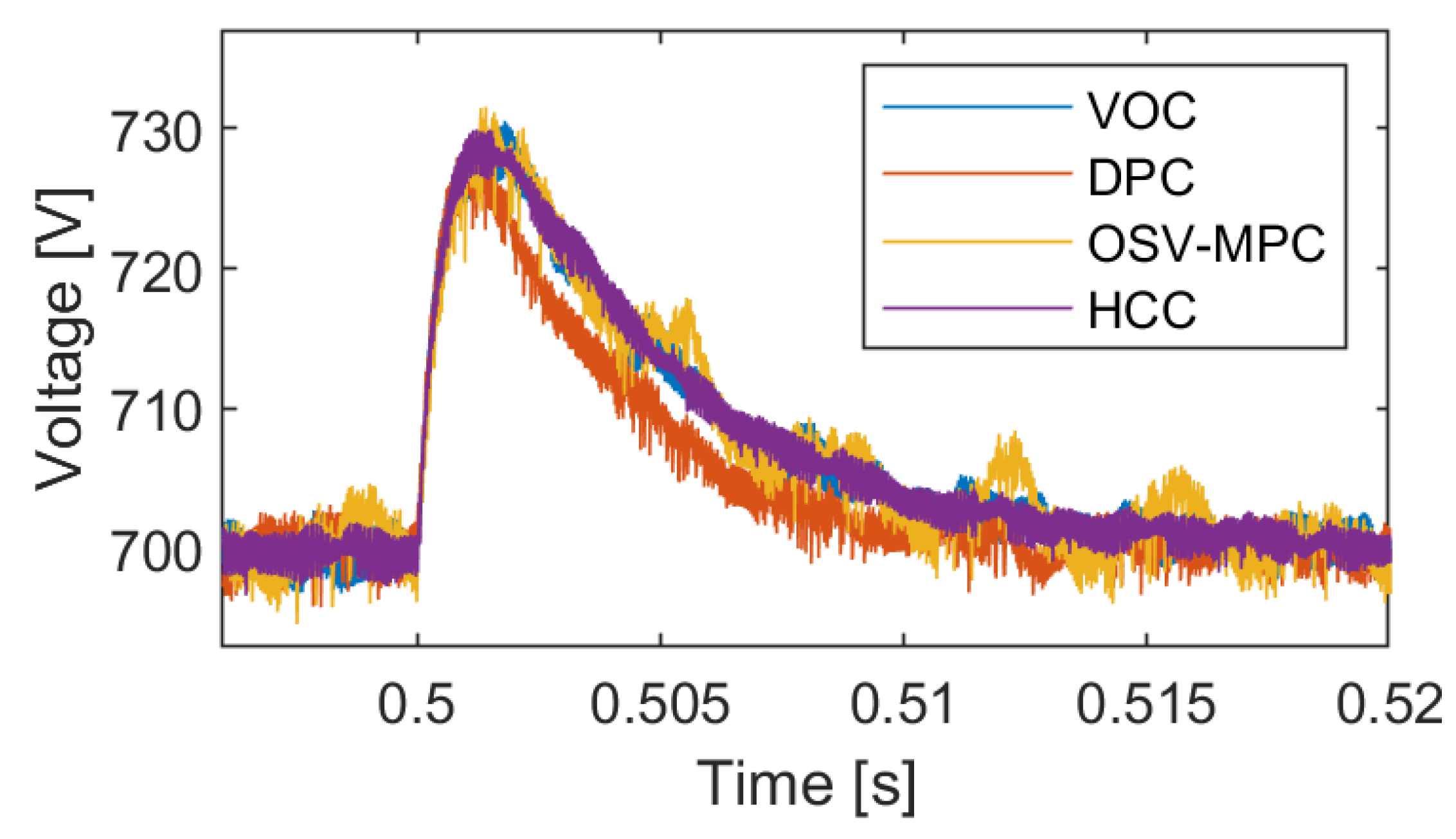
When the load drop of 20% occurs, all control systems see approximately a 30 V increase in voltage before settling back to the setpoint within 20 ms, as shown in Figure 32. Again, DPC is the fastest to react.
While it was attempted to obtain a 20 kHz switching frequency in all converters, it is not easily tunable for the control systems that do not use a modulator. Therefore, DPC and MPC are switching at lower frequencies, as shown in Figure 33. The switching frequency of VOC stays at 20 kHz. The switching frequency of HCC is 20 kHz on average. However, it varies between 18 and 22 kHz. For DPC and MPC, the switching frequencies average around 17.5 and 18.7 kHz, respectively, with a spread of around 2 kHz from the average.
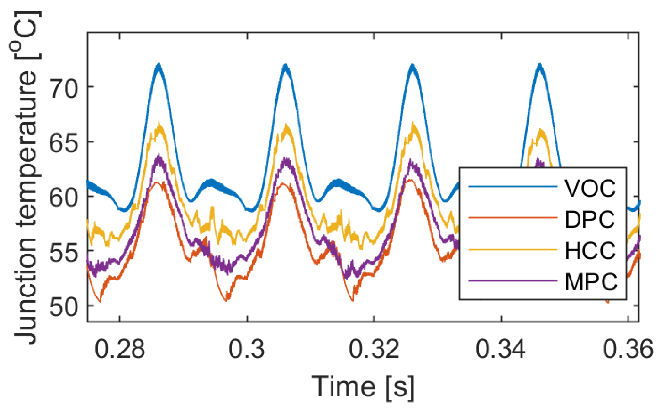
The thermal behavior of the converter is evaluated using an electro-thermal model from [64]. Even though the converter and the cooling system are the same for all cases, the choice of control system affects even the MOSFET junction temperature, as shown in Figure 34. The swing of the junction temperature is the main stressor of the switches [65]. The VOC and HCC have roughly the same switching frequency. However, the VOC demonstrates higher average temperatures and higher temperature swings.
To conclude, all the control systems compared in this section use a similar number of sensors. Most of them have sensorless implementations that skip either current or voltage sensors in the literature. VOC has a fixed switching frequency, which makes it easier to design the filters, estimate losses, and design the cooling system. Moreover, using a carrier-based PWM makes it a suitable option for parallel converter systems with carrier interleaving. DPC, MPC, and HCC do not require modulators, which reduces the computational burden, but they have variable switching frequencies, which is a disadvantage. Moreover, as demonstrated in the above simulation, it is not easy to tune the average switching frequency for DPC and MPC. While for HCC, the switching frequency may change based on the operating conditions [42].

5. Modular AFE

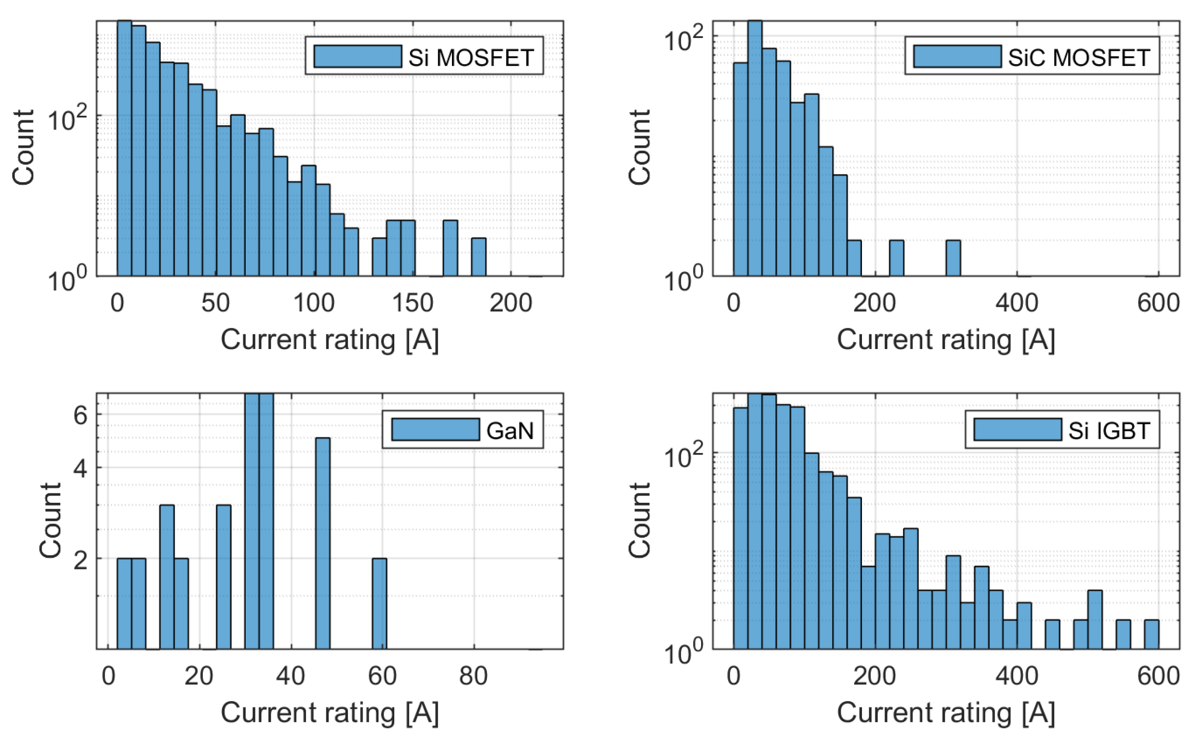
With the increasing tendency for high-power chargers in the megawatt range for ultra-fast charging, the standard solution of using a simple single converter is not feasible. Figure 35 shows the distribution of available discrete semiconductors by current rating for applications above 400 V based on the data of over 20,000 devices from Digi-Key Electronics. Please note that the y-axis is a logarithmic scale, so the actual difference between component availability at different current ratings is even more drastic. The majority of Si MOSFETs (99.08%) are available under 100 A and 650 V. While SiC MOSFETs can go much higher in terms of both current and voltage ratings, 87% of SiC MOSFETs are also under 100 A. The majority of available GaN components are rated below 400 V; therefore, the choice of GaN components is very limited. The Si IGBTs have the highest current ratings among all. However, they have much longer switching times compared to the MOSFETs, which means they cannot operate at higher switching frequencies and would result in much bigger filter component sizes. The clear tendency shown in Figure 35 is that with increasing power rating, the number of available components decreases. Building a fast charger AFE would require specialty components with low availability and high cost. The modular approach can be used to solve the issues of component availability in addition to improving system reliability, performance, grid impact, and thermal management.
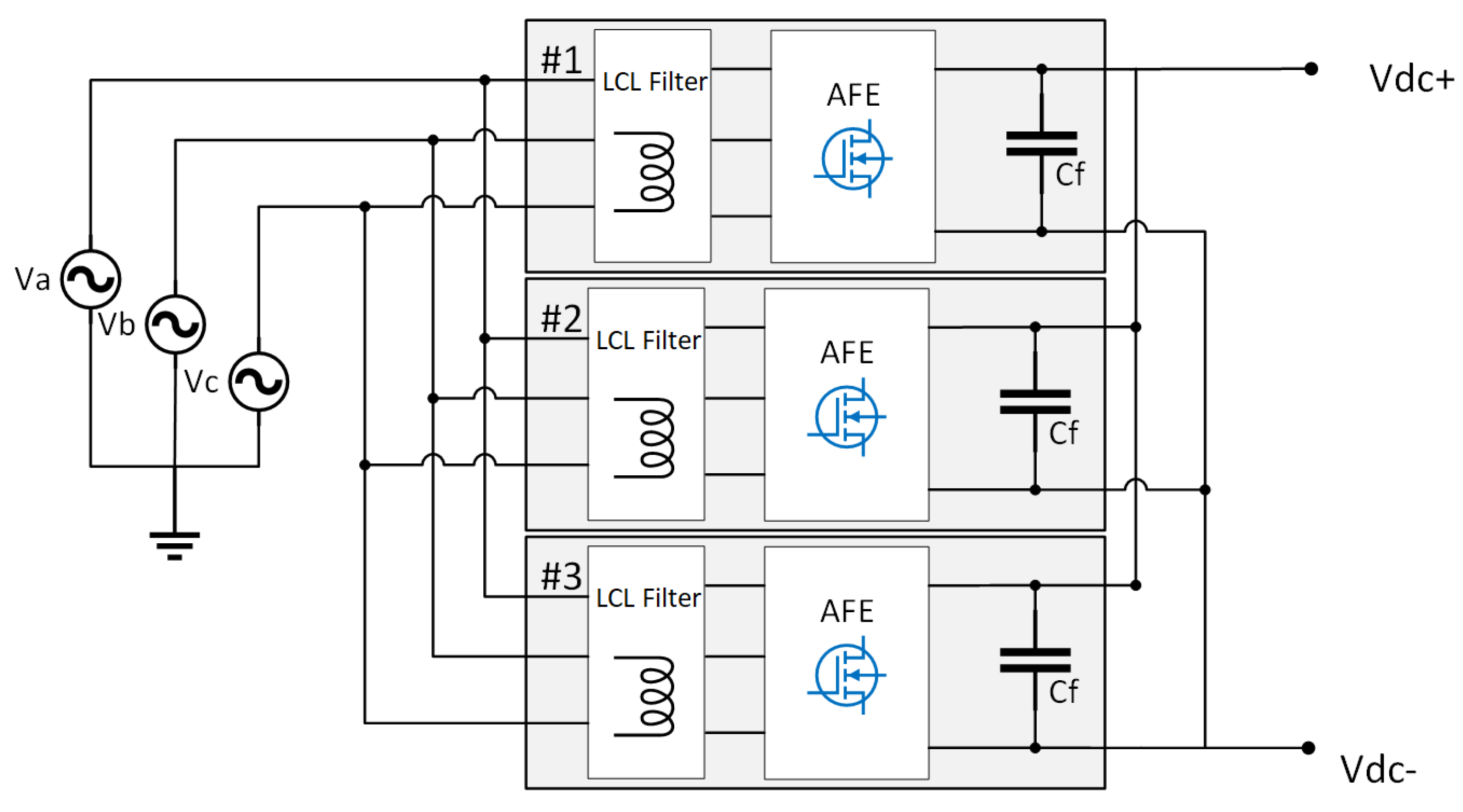
The concept of modularity means that the system is divided into smaller parts, “modules” that can be individually designed, modified, and replaced by other “modules”. Moreover, modules can be exchanged with other systems. When applied to the AFE system, one whole AFE rectifier can be considered a module, and several modules can be joined into one system to build a parallel converter setup, as shown in Figure 36.
A modular approach using parallel converters is advantageous in several ways. One, it allows building high-power systems without the need to use high-power rated components that are costly and not easily available. Moreover, using the same set of modules, different power-rated systems can be built. Using this approach, one can increase or decrease system power rating during operation to optimize efficiency [66]. Failed modules can be isolated to allow the rest of the system to continue operation [67]. Extra modules can be used as a backup to increase system reliability. Therefore, using parallel AFE can be beneficial for system efficiency, reliability, and versatility [68]. Using a modular approach decreases stress on individual components, which results in higher reliability [64]. Figure 37 demonstrates how the efficiency of a 30 kW rectifier system can be improved by using a three-module system instead of a non-modular system.
Moreover, a parallel configuration of AFE allows PWM carrier signal interleaving, which decreases grid current THD [69]. In the case components of sufficient power rating are available, the modular approach is almost always costlier due to the higher number of components, even though part of the cost can be offset with increased efficiency and reliability. Moreover, using parallel AFE configuration can result in circulating currents and increased complexity of the control system [70,71]. This topic will be covered more in the next subsection.

5.1. Control of Parallel Converters

When transitioning from a single rectifier to a modular system, there are a number of new problems and possibilities that require additional functions of the control system. First, there is an issue common for all parallel connected AFE rectifiers—circulating currents.

5.1.1. Circulating Currents

Zero sequence circulating currents (ZSCC) appear on the grid side of the parallel converters if the switching patterns of the modules are not completely synchronized or have different line impedance [70]. The switching patterns might be different because of synchronization delay or if carrier signal interleaving is used. According to [71], different modulation voltages can also cause ZSCC. In addition to ZSCC, there are also nonzero-sequence circulating currents [72]. There are several ways to solve the issue of circulating currents. First, there is the hardware approach. Each converter is isolated from other converters by low-frequency transformers. Another hardware option is to introduce high-impedance coupled inductors in the ZSCC path [71]. Both of these solutions are costly and bulky [72]. In order to avoid the extra cost of introducing new hardware components, open-loop or closed-loop control strategies, or special switching methods can be used to solve ZSCC issues [71]. An average model that helps to better understand the nature of circulating currents is proposed in [72].

5.1.2. Interleaving

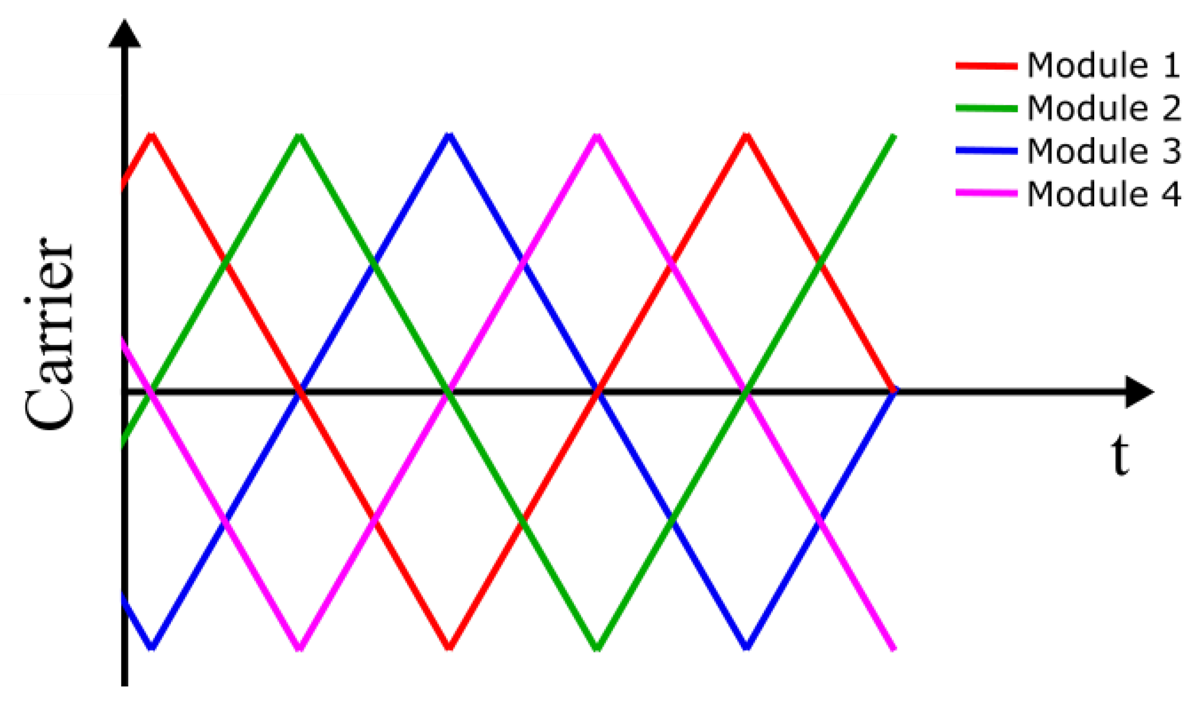
The use of carrier signal interleaving is a well-established practice [69]. The idea is to introduce a phase shift between the carrier signals of different modules in a way that allows the reduction of the harmonic distortion of the grid side currents [67,68]. Normally, the phase shift between carrier signals is selected as 360 n , where n is the total number of active modules in the system, as shown in Figure 38. However, as mentioned earlier, the interleaving of carrier signals creates circulating currents [71].

5.1.3. System Power Adapting

One of the major advantages of parallel converters comes with the ability to adapt the operating power level based on the load. Adjusting the number of active modules allows the optimization of the efficiency of the system for slowly varying load operation.

5.1.4. Failure Management

In a parallel AFE system, the failure of one module can be mitigated in several steps. First, the failed module needs to be isolated. Then, the system can either operate at reduced capacity or, if a standby module is available, it can replace the failed module. The standby module can be a dedicated extra module or a module that has been deactivated due to lower-power requirements during operation [67].

5.2. Centralized Control of Parallel Converters

As mentioned in Section 5, parallel converters can be controlled by one centralized controller or by a system of distributed controllers [68,73,74,75,76,77]. Each option has its advantages and disadvantages, as described in this section.
The basic control strategy for parallel converters is to use one controller, which takes all the sensor readings as an input, and issues gate signals for all the switches. Normally, there is a common three-phase voltage sensor on the grid side and a common DC voltage sensor at the output. The three-phase current sensors are separate for each module [69]. If cascaded control, where voltage is controlled in the outer loop and currents are controlled in the inner loop, is used, then there will be one common voltage control loop and separate current control loops for each module. The centralized control systems for systems of parallel converters have been successfully implemented in [68,73].

5.3. Distributed Master-Slave

Nowadays, the majority of distributed controller system implementations use master-slave control, where one main “master” controller is in charge of synchronizing the operation of all modules and sharing the load. The failure of the master controller would cause the failure of the entire system. A system with equal controllers where each controller has master capabilities and can adjust during operation has been introduced in [75]. In both cases, the outer control loop runs on the master controller, and the signal is conveyed to the slave modules via a data bus. Therefore, the delay in the data bus appears within the control loop and can cause instability in the system [76]. This delay in the data bus is larger for systems with many modules [77].

5.4. Distributed Masterless

Alternatively to the master-slave system is a masterless control system [66]. Here all modules are capable of running both outer and inner control loops. The modules exchange relevant data through a data bus. This information is used to distribute the load between modules and adjust the system operation. However, since the signals from the data bus do not appear within the control loops, the system is more resilient in the case of data bus delays.

6. Cooling System

The cooling technique is crucial for AFE rectifiers as it can affect the system efficiency and lifetime. Moreover, cooling systems are one of the roadblocks in the development of ultra-fast chargers. There are several types of cooling systems commonly used for power electronic converters: forced air cooling, liquid cooling, and other more complex cooling methods [24]. Depending on the type of charger, i.e., on-board or off-board, the cooling system for AFE rectifiers will have different requirements. The main parameters are: the space and weight limitations, power level, and allowed temperature range. Since this paper focuses on high-power off-board chargers, the space and weight constraints are of reduced importance, while the dissipated power levels will be extremely high. If the best-case system efficiency of 97% is assumed, the dissipated power levels for Level 3 chargers will range from 660 W for a 22 kW system up to 10.5 kW for a 350 kW system. Whereas for ultra-fast chargers of above 400 kW power rating, the dissipated power will be more than 12 kW.

6.1. Air Cooling

Air cooling is relatively simple and cost-effective [24]. It also uses fewer components compared to liquid cooling, which may have a positive effect on the power density of the system [78]. Air cooling can be either non-forced or forced air cooling; forced air cooling can remove more heat from the system.
Air cooling can be used for AFE rectifiers if one or several of the following conditions apply: if the power is low, the space limitations are not crucial (off-board charger), or the AFE can operate at higher temperatures (WBG devices). In some cases, using design and control optimization, researchers were able to succeed in using only natural (non-forced) cooling for SiC chargers [79] of up to 2 kW, which is below the power rating of DC chargers. The optimized design of the heatsink structure can further increase the efficiency of air-cooled systems [80]. However, according to [81], in forced air-cooled systems, the outside corrosive elements can easily enter and damage the system, causing shortened lifetime and difficult maintenance. A 90 kW modular DC charger that consists of 15 kW modules achieves 95% efficiency using forced air cooling in [82]. Moreover, a protective air inlet design is used to minimize the dust and particles entering the charger. Some of the commercially available DC chargers use forced air cooling of the power electronics. For example, EVBox Troniq modular (90 kW–240 kW) [83] and Blink HPC-180-480 (60 kW–360 kW) [84] use forced air cooling of the power electronics while providing optional liquid cooling for the cables.

6.2. Liquid Cooling

Liquid cooling has higher heat transfer efficiency [85]. Moreover, liquid-cooled systems have a high ingress protection class [81]. The type of liquid used in this cooling method and the exact construction can vary from case to case. According to [81], liquid cooling systems have a risk of liquid leakage, the equipment is complex, and the cost is high. A combination of a modular approach and liquid cooling can be a suitable solution for high-power fast chargers. An AFE drive with 200 kW modules presented in [86] is able to achieve a 97% efficiency using a liquid cooling system with water. A liquid-cooled 100 kW two-stage fast charger with 95% efficiency and modular design is presented in [87]. A 360 kW liquid-cooled DC charger is available commercially from Dekon [88].

7. Reliability

The reliability of an AFE rectifier is evaluated in several stages, as shown in Figure 39. First, the lifetime assessment for each individual component of the AFE is performed. Then a series of calculations identify the system-level reliability based on the component lifetime and system configuration. In the following subsections, each of these stages is discussed in detail.

7.1. Component Level Reliability

In this subsection, the reliability of the active power switches and capacitors is discussed since they are the two components in AFE rectifiers prone to failure [89,90].

7.1.1. Power Semiconductors Lifetime Model

The two main stressors of the active switches are the junction temperature and temperature swing [91]. To predict the lifetime of the component, the aforementioned parameters can be measured or estimated from the electro-thermal model for a given mission profile. In the case of an AFE rectifier in the charging application, the mission profile is the load power profile that corresponds to EV battery charging. A number of different lifetime models have been presented in the literature. The original LESIT model derived in the 1990s is given in Equation (4) [92]. This model takes into account the effect of the switch junction temperature medium value T j m and swing Δ T j on the component lifetime. However, newer models have been developed that also take into account the effect of the load pulse duration, bond aspect ratio, etc. [93]. The data necessary for the lifetime model are extracted from the electro-thermal simulation data using the Rainflow counting algorithm [65].
N f = A × Δ T j α × e Q R × T j m
These models provide N f number of cycles to failure, which is then used to calculate the life consumption L C s w of the switch for the given mission profile using Equation (5).
L C s w = i = 1 k n i N f i

7.1.2. Capacitor Lifetime Model

There are several failure modes of a capacitor, namely: short circuit, wear-out, and open circuit depending on the type of the capacitor. The critical stressors causing these failures are temperature, voltage, current, and vibration [32]. Among those, the two main stressors that impact the lifetime of a capacitor are the voltage and the temperature [91]. First, the lifetime under applied voltage and temperature is calculated, taking into account the capacitor’s lifetime under rated operating conditions [91].
L t = L o · 2 T o T t n 1 V t V o n 2
L o is the component’s lifetime under the rated temperature T o and voltage V o . While L t is the component lifetime under the applied temperature T t and voltage V t . n 1 is the temperature-dependent constant. n 2 is the voltage stress exponent, which is equal to 2.5 if the applied voltage is within 60–100% of the rated voltage [94]. Moreover, the lifetime estimation model of an electrolytic capacitor given in [94] also takes into account the effect of DC link current ripples, as electrolytic capacitors are the most susceptible to damage from high-frequency ripples.
Then, the accumulated damage on the capacitors is calculated using (7).
A D c = l t L t

7.1.3. Reliability Analysis

After obtaining the information on accumulated damage on the components, a Monte Carlo analysis can be employed to statistically evaluate the reliability of the component. After that, the Weibull Cumulative Distribution Function (CDF) is fit to the output of Monte Carlo analysis to obtain the reliability curve of the component.

7.2. System Level Reliability

To evaluate the system level reliability of the AFE rectifier, it is assumed that the whole system fails if a single component fails. In this case, the reliability of the AFE rectifier is estimated by using a series reliability network model [65,91]. If the AFE rectifier is built using an active switch with an internal diode, e.g., MOSFET, then Equation (10) can describe the system level reliability estimation of a simple six-switch two-level AFE.
R A F E = R M O S F E T 6 · R c a p
If an external anti-parallel diode is used with an active switch, e.g., IGBT, then the system level reliability of a six-switch converter can be estimated using Equation (11).
R A F E = R I G B T 6 · R D i o d e 6 · R c a p
Therefore, the AFE topologies, such as NPC and T-type rectifier, would be at a disadvantage due to the higher number of components when compared to the simple six-switch two-level topology. When several parallel converters are employed in a modular fast charger system, if one of them fails, the system can continue operation with limited power capabilities. In modular systems with no standby modules, the loss of performance will occur when even one module fails. Therefore, a series reliability network is used:
R s y s 1 = R A F E n
The loss of primary function will occur if all modules fail. Hence the reliability of the modular AFE system can be described using a parallel reliability network:
R s y s 2 = 1 ( 1 R A F E ) n

8. Trends and Future Outlook

With the increasing demand for ultra-fast chargers, the power ratings of PECs in EV charging applications are rapidly increasing. With the higher power, there is a tendency towards using higher power density switching devices, such as WBG semiconductors, modular design, more efficient cooling, a control system that can handle the increasing system complexity, and also aiming at longer lifetime for the chargers.
The increasing interest in the WBG EV chargers is evident from the amount of IEEE publications on the subject: there were only ten publications about WBG EV chargers before 2013, 60 papers in 2013–2017, and 117 papers in 2018–2022. WBG devices are being used more commonly in EV chargers, both on-board and off-board [95]. From their first emergence in the 1990s, the SiC MOSFETs increased their current capabilities from under 1 A to over 200 A. In the next years, the research will focus on increasing the operating power, voltage, temperature, and frequency of individual switches even further by experimenting with new materials and manufacturing techniques. Novel packaging methods with integrated cooling systems will be more common due to the high power dissipation requirements of the new generation of EV chargers [96].
In recent years, modular manufacturing has become a trend in many industries with the increase in demand for high-power fast chargers and the need for faster manufacturing. Modular converters are thereof used in rapid chargers to avoid using high current components [97] and to have more scalable, versatile [98,99], fail-safe [67], and efficient [100] systems. Moreover, if interleaving between modules is used, they can reduce ripples in the output [101] and input [67] charger currents. Moreover, further control optimization is enabled by modularity, which leads to overall higher reliability and lifetime.
With the rise in the capabilities of digital computing, chargers are becoming “smarter” and using new control systems based on intelligent algorithms. Charger control systems with the ability for grid conditioning and 2G are forecasted to be more commonplace due to the expected high penetration of the fast chargers into the grid. Another way in which chargers are becoming “smarter” is through the use of condition monitoring and preventive maintenance to improve the system’s reliability and lifetime.

Author Contributions

Conceptualization, A.Z., S.C., T.G. and O.H.; simulations, A.Z.; writing—original draft preparation, A.Z.; writing—review and editing, T.G., E.A., H.R., S.C., M.E.B. and O.H.; project administration, T.G., M.E.B. and O.H.; funding acquisition, T.G., M.E.B. and O.H. All authors have read and agreed to the published version of the manuscript.

Funding

This research is part of the ModulAr SBO project funded and supported by Flanders Make vzw, the strategic research center for the manufacturing industry.

Data Availability Statement

The data presented in this study are available on request from the corresponding author.

Conflicts of Interest

The authors declare no conflict of interest.

References

  1. IEA. Global Electric Vehicle Stock by Region, 2010–2020; Technical Report; IEA: Paris, France, 2010.
  2. Electric Vehicle Charging Infrastructure Market Size, Share & Trends Analysis Report by Charger Type, by Connector, b Application, by Region, and Segment Forecasts, 2022–2030. Technical Report, Grand View Research. 2022. Available online: https://www.marketresearch.com/Grand-View-Research-v4060/Electric-Vehicle-Charging-Infrastructure-Size-31517658/ (accessed on 10 September 2022).
  3. Yilmaz, M.; Krein, P.T. Review of Battery Charger Topologies, Charging Power Levels, and Infrastructure for Plug-In Electric and Hybrid Vehicles. IEEE Trans. Power Electron. 2013, 28, 2151–2169. [Google Scholar] [CrossRef]
  4. Zamani, M.; Nagrial, M.; Rizk, J.; Hellany, A. Electric Vehicles Charging: Review of Current Status. In Proceedings of the 2018 Australasian Universities Power Engineering Conference (AUPEC), IEEE, Auckland, New Zealand, 27–30 November 2018; pp. 1–5. [Google Scholar] [CrossRef]
  5. Jaman, S.; Chakraborty, S.; Tran, D.D.; Geury, T.; El Baghdadi, M.; Hegazy, O. Review on Integrated On-Board Charger-Traction Systems: V2G Topologies, Control Approaches, Standards and Power Density State-of-the-Art for Electric Vehicle. Energies 2022, 15, 5376. [Google Scholar] [CrossRef]
  6. Rasool, H.; Verbrugge, B.; Zhaksylyk, A.; Tran, T.M.; Baghdadi, M.E.; Geury, T.; Hegazy, O. Design Optimization and Electro-Thermal Modeling of an Off-Board Charging System for Electric Bus Applications. IEEE Access 2021, 9, 84501–84519. [Google Scholar] [CrossRef]
  7. Amanor-Boadu, J.M.; Guiseppi-Elie, A. Improved Performance of Li-ion Polymer Batteries Through Improved Pulse Charging Algorithm. Appl. Sci. 2020, 10, 895. [Google Scholar] [CrossRef] [Green Version]
  8. Safayatullah, M.; Elrais, M.T.; Ghosh, S.; Rezaii, R.; Batarseh, I. A Comprehensive Review of Power Converter Topologies and Control Methods for Electric Vehicle Fast Charging Applications. IEEE Access 2022, 10, 40753–40793. [Google Scholar] [CrossRef]
  9. Kolar, J.W.; Friedli, T. The Essence of Three-Phase PFC Rectifier Systems—Part I. IEEE Trans. Power Electron. 2013, 28, 176–198. [Google Scholar] [CrossRef]
  10. Friedli, T.; Hartmann, M.; Kolar, J.W. The Essence of Three-Phase PFC Rectifier Systems—Part II. IEEE Trans. Power Electron. 2014, 29, 543–560. [Google Scholar] [CrossRef]
  11. Athari, H.; Niroomand, M.; Ataei, M. Review and Classification of Control Systems in Grid-tied Inverters. Renew. Sustain. Energy Rev. 2017, 72, 1167–1176. [Google Scholar] [CrossRef]
  12. Tahir, S.; Wang, J.; Baloch, M.; Kaloi, G. Digital Control Techniques Based on Voltage Source Inverters in Renewable Energy Applications: A Review. Electronics 2018, 7, 18. [Google Scholar] [CrossRef] [Green Version]
  13. Malinowski, M.; Kazmierkowski, M.; Trzynadlowski, A. A comparative study of control techniques for PWM rectifiers in AC adjustable speed drives. IEEE Trans. Power Electron. 2003, 18, 1390–1396. [Google Scholar] [CrossRef]
  14. Zabetian-Hosseini, A.; Joos, G.; Boulet, B. Distributed Control Design for V2G in DC Fast Charging Stations. In Proceedings of the 2021 IEEE Energy Conversion Congress and Exposition (ECCE), IEEE, Vancouver, BC, Canada, 10–14 October 2021; pp. 655–661. [Google Scholar] [CrossRef]
  15. Chandler, S.; Gartner, J.; Jones, D. Integrating Electric Vehicles with Energy Storage and Grids: New Technology and Specific Capabilities Spur Numerous Applications. IEEE Electrif. Mag. 2018, 6, 38–43. [Google Scholar] [CrossRef]
  16. Krasselt, P.; Boßle, J.; Suriyah, M.; Leibfried, T. DC-Electric Vehicle Supply Equipment Operation Strategies for Enhanced Utility Grid Voltage Stability. World Electr. Veh. J. 2015, 7, 530–539. [Google Scholar] [CrossRef] [Green Version]
  17. Halbig, J. 15 kW Bidirectional Vienna PFC. In Proceedings of the APEC2020, New Orleans, LA, USA, 15–19 March 2020. [Google Scholar]
  18. Schweizer, M.; Kolar, J.W. Design and Implementation of a Highly Efficient Three-Level T-Type Converter for Low-Voltage Applications. IEEE Trans. Power Electron. 2013, 28, 899–907. [Google Scholar] [CrossRef]
  19. Qian, H.; Xu, J.; Hu, Y.; Xie, S. Design and Comparison of High-Order Output Filters for Grid-Connected Converters with Low Switching Frequency. In Proceedings of the 2021 IEEE 16th Conference on Industrial Electronics and Applications (ICIEA), IEEE, Chengdu, China, 1–4 August 2021; pp. 894–899. [Google Scholar] [CrossRef]
  20. Yagnik, U.P.; Solanki, M.D. Comparison of L, LC & LCL filter for grid connected converter. In Proceedings of the 2017 International Conference on Trends in Electronics and Informatics (ICEI), IEEE, Tirunelveli, India, 11–12 May 2017; pp. 455–458. [Google Scholar] [CrossRef]
  21. Su, G.J. Comparison of Si, SiC, and GaN based Isolation Converters for Onboard Charger Applications. In Proceedings of the 2018 IEEE Energy Conversion Congress and Exposition (ECCE), IEEE, Portland, OR, USA, 23–27 September 2018; pp. 1233–1239. [Google Scholar] [CrossRef]
  22. Gu, X.; Shui, Q.; Myles, C.; Gundersen, M. Comparison of Si, GaAs, SiC and GaN FET-type switches for pulsed power applications. In Proceedings of the Digest of Technical Papers, PPC-2003, 14th IEEE International Pulsed Power Conference (IEEE Cat. No.03CH37472), IEEE, Dallas, TX, USA, 15–18 June 2003; pp. 362–365. [Google Scholar] [CrossRef] [Green Version]
  23. Liu, G.; Bai, K.H.; McAmmond, M.; Brown, A.; Johnson, P.M.; Taylor, A.; Lu, J. Comparison of SiC MOSFETs and GaN HEMTs based high-efficiency high-power-density 7.2 kWEV battery chargers. In Proceedings of the 2017 IEEE 5th Workshop on Wide Bandgap Power Devices and Applications (WiPDA), IEEE, Albuquerque, NM, USA, 30 October–1 November 2017; pp. 391–397. [Google Scholar] [CrossRef]
  24. Abramushkina, E.; Zhaksylyk, A.; Geury, T.; El Baghdadi, M.; Hegazy, O. A Thorough Review of Cooling Concepts and Thermal Management Techniques for Automotive WBG Inverters: Topology, Technology and Integration Level. Energies 2021, 14, 4981. [Google Scholar] [CrossRef]
  25. Zhang, D.; Guacci, M.; Haider, M.; Bortis, D.; Kolar, J.W.; Everts, J. Three-Phase Bidirectional Buck-Boost Current DC-Link EV Battery Charger Featuring a Wide Output Voltage Range of 200 to 1000 V. In Proceedings of the 2020 IEEE Energy Conversion Congress and Exposition (ECCE), IEEE, Detroit, MI, USA, 11–15 October 2020; pp. 4555–4562. [Google Scholar] [CrossRef]
  26. Liu, Z.; Li, B.; Lee, F.C.; Li, Q. High-Efficiency High-Density Critical Mode Rectifier/Inverter for WBG-Device-Based On-Board Charger. IEEE Trans. Ind. Electron. 2017, 64, 9114–9123. [Google Scholar] [CrossRef]
  27. Flack, T.J.; Pushpakaran, B.N.; Bayne, S.B. GaN Technology for Power Electronic Applications: A Review. J. Electron. Mater. 2016, 45, 2673–2682. [Google Scholar] [CrossRef]
  28. Wide Bandgap Semiconductors (SiC/GaN). Available online: https://www.infineon.com/cms/en/product/technology/wide-bandgap-semiconductors-sic-gan/ (accessed on 23 October 2022).
  29. She, X.; Huang, A.Q.; Lucia, O.; Ozpineci, B. Review of Silicon Carbide Power Devices and Their Applications. IEEE Trans. Ind. Electron. 2017, 64, 8193–8205. [Google Scholar] [CrossRef]
  30. Sen, S.; Zhang, L.; Chen, T.; Zhang, J.; Huang, A.Q. Three-phase Medium Voltage DC Fast Charger based on Single-stage Soft-switching Topology. In Proceedings of the 2018 IEEE Transportation Electrification Conference and Expo (ITEC), IEEE, Long Beach, CA, USA, 13–15 June 2018; pp. 1123–1128. [Google Scholar] [CrossRef]
  31. Srdic, S.; Zhang, C.; Liang, X.; Yu, W.; Lukic, S. A SiC-based power converter module for medium-voltage fast charger for plug-in electric vehicles. In Proceedings of the 2016 IEEE Applied Power Electronics Conference and Exposition (APEC), IEEE, Long Beach, CA, USA, 20–24 March 2016; pp. 2714–2719. [Google Scholar] [CrossRef]
  32. Wang, H.; Blaabjerg, F. Reliability of Capacitors for DC-Link Applications in Power Electronic Converters—An Overview. IEEE Trans. Ind. Appl. 2014, 50, 3569–3578. [Google Scholar] [CrossRef] [Green Version]
  33. Das, J. Harmonic Distortion Limits According to Standards. In Power System Harmonics and Passive Filter Designs; John Wiley & Sons, Inc: Hoboken, NJ, USA, 2015; pp. 427–451. [Google Scholar] [CrossRef]
  34. Das, J.C. Harmonic Reduction at the Source. In Power System Harmonics and Passive Filter Designs; Wiley and Sons: Hoboken, NJ, USA, 2015; pp. 229–279. [Google Scholar] [CrossRef]
  35. Sanjuan, S. Voltage Oriented Control of Three-Phase Boost PWM Converters. Ph.D. Thesis, Chalmers University of Technology, Göteborg, Sweeden, 2010. [Google Scholar]
  36. Kazmierkowski, M.; Krishnan, R.; Blaabjerg, F. Control in Power Electronics; Elsevier: Amsterdam, The Netherland, 2002. [Google Scholar] [CrossRef]
  37. Hojabri, M.; Hojabri, M. Design, Application and Comparison of Passive Filters for Three-Phase Grid-Connected Renewable Energy Systems. ARPN J. Eng. Appl. Sci. 2015, 10, 10691–10697. [Google Scholar]
  38. Araujo, S.V.; Engler, A.; Sahan, B.; Antunes, F.L.M. LCL filter design for grid-connected NPC inverters in offshore wind turbines. In Proceedings of the 2007 7th Internatonal Conference on Power Electronics, IEEE, Daegu, Republic of Korea, 22–26 October 2007; pp. 1133–1138. [Google Scholar] [CrossRef]
  39. IEEE. 519-2014—IEEE Recommended Practice and Requirements for Harmonic Control in Electric Power Systems; IEEE Std 519-2014 (Revision of IEEE Std 519-1992); IEEE: Piscataway, NJ, USA, 2014; pp. 1–29. [Google Scholar] [CrossRef]
  40. Całus, D. Analysis of the Thermal Processes in an Electromagnetic Mill. Energies 2022, 15, 7899. [Google Scholar] [CrossRef]
  41. Liu, Y.; See, K.Y.; Yin, S.; Simanjorang, R.; Tong, C.F.; Nawawi, A.; Lai, J.S.J. LCL Filter Design of a 50-kW 60-kHz SiC Inverter with Size and Thermal Considerations for Aerospace Applications. IEEE Trans. Ind. Electron. 2017, 64, 8321–8333. [Google Scholar] [CrossRef]
  42. Kazmierkowski, M.; Malesani, L. Current control techniques for three-phase voltage-source PWM converters: A survey. IEEE Trans. Ind. Electron. 1998, 45, 691–703. [Google Scholar] [CrossRef]
  43. Krause, P.; Wasynczuk, O.; Sudhoff, S.; Pekarek, S. Reference-Frame Theory. In Analysis of Electric Machinery and Drive Systems; John Wiley & Sons, Ltd.: Hoboken, NJ, USA, 2013; Chapter 3; pp. 86–120. [Google Scholar] [CrossRef]
  44. Sridharan, K.; Babu, B.C. A Novel Adaptive Bandpass Filter Based PLL for Grid Synchronization Under Distorted Grid Conditions. IEEE Trans. Instrum. Meas. 2022, 71, 9003111. [Google Scholar] [CrossRef]
  45. Golestan, S.; Guerrero, J.M.; Vasquez, J.C. Three-Phase PLLs: A Review of Recent Advances. IEEE Trans. Power Electron. 2017, 32, 1894–1907. [Google Scholar] [CrossRef] [Green Version]
  46. Zhu, D.; Zhou, S.; Zou, X.; Kang, Y. Improved Design of PLL Controller for <i>LCL</i> -Type Grid-Connected Converter in Weak Grid. IEEE Trans. Power Electron. 2020, 35, 4715–4727. [Google Scholar] [CrossRef]
  47. Bouafia, A.; Gaubert, J.P.; Krim, F.; Chaoui, A. Unity Power Factor Operation of Three-Phase PWM Rectifier Based on Direct Power Control. In Proceedings of the EUROCON 2007—The International Conference on “Computer as a Tool”, IEEE, Warsaw, Poland, 9–12 September 2007; pp. 1518–1523. [Google Scholar] [CrossRef]
  48. Gopalan, S. A comparative study of control techniques for three phase PWM rectifier. In Proceedings of the 2016 10th International Conference on Intelligent Systems and Control (ISCO), IEEE, Coimbatore, India, 7–8 January 2016; pp. 1–8. [Google Scholar] [CrossRef]
  49. Cano, J.M.; Jatskevich, J.; Norniella, J.G.; Davoudi, A.; Wang, X.; Martinez, J.A.; Mehrizi-Sani, A.; Saeedifard, M.; Aliprantis, D.C. Dynamic Average-Value Modeling of Direct Power-Controlled Active Front-End Rectifiers. IEEE Trans. Power Deliv. 2014, 29, 2458–2466. [Google Scholar] [CrossRef]
  50. Vazquez, S.; Leon, J.I.; Franquelo, L.G.; Rodriguez, J.; Young, H.A.; Marquez, A.; Zanchetta, P. Model Predictive Control: A Review of Its Applications in Power Electronics. IEEE Ind. Electron. Mag. 2014, 8, 16–31. [Google Scholar] [CrossRef]
  51. Vazquez, S.; Sanchez, J.; Carrasco, J.; Leon, J.; Galvan, E. A Model-Based Direct Power Control for Three-Phase Power Converters. IEEE Trans. Ind. Electron. 2008, 55, 1647–1657. [Google Scholar] [CrossRef]
  52. Akter, M.P.; Mekhilef, S.; Tan, N.M.L.; Akagi, H. Model Predictive Control of Bidirectional AC-DC Converter for Energy Storage System. J. Electr. Eng. Technol. 2015, 10, 165–175. [Google Scholar] [CrossRef] [Green Version]
  53. Bartsch, A.G.; Negri, G.H.; Cavalca, M.S.; De Oliveira, J.; Nied, A. Cost function tuning methodology for FCS-MPC applied to PMSM drives. In Proceedings of the 14th Brazilian Power Electronics Conference, COBEP 2017, Juiz de Fora, Brazil, 19–22 November 2017; Volume 2018. [Google Scholar] [CrossRef]
  54. Preindl, M.; Schaltz, E.; Thogersen, P. Switching Frequency Reduction Using Model Predictive Direct Current Control for High-Power Voltage Source Inverters. IEEE Trans. Ind. Electron. 2011, 58, 2826–2835. [Google Scholar] [CrossRef]
  55. Ali, S.U.; Waqar, A.; Elavarasan, R.M.; Pugazhendhi, R.; Rahman, M.M.; Islam, M.R.; Aamir, M. Model Predictive Control for three phase rectifier with grid connected and standalone mode of operation. In Proceedings of the 2021 31st Australasian Universities Power Engineering Conference (AUPEC), IEEE, Perth, Australia, 26–30 September 2021; pp. 1–7. [Google Scholar] [CrossRef]
  56. Jun, E.S.; Kim, J.C.; Kwak, S. Model Predictive Virtual Flux Control Method for Three-phase AFE Rectifiers Robust Against Supply Harmonics and Unbalance. In Proceedings of the 2019 10th International Conference on Power Electronics and ECCE Asia (ICPE 2019—ECCE Asia), IEEE, Busan, Republic of Korea, 27–31 May 2019; pp. 1–5. [Google Scholar] [CrossRef]
  57. Vazquez, S.; Rodriguez, J.; Rivera, M.; Franquelo, L.G.; Norambuena, M. Model Predictive Control for Power Converters and Drives: Advances and Trends. IEEE Trans. Ind. Electron. 2017, 64, 935–947. [Google Scholar] [CrossRef] [Green Version]
  58. Leon, J.I.; Kouro, S.; Franquelo, L.G.; Rodriguez, J.; Wu, B. The Essential Role and the Continuous Evolution of Modulation Techniques for Voltage-Source Inverters in the Past, Present, and Future Power Electronics. IEEE Trans. Ind. Electron. 2016, 63, 2688–2701. [Google Scholar] [CrossRef]
  59. Suhara, E.M.; Nandakumar, M. Analysis of hysteresis current control techniques for three phase PWM rectifiers. In Proceedings of the 2015 IEEE International Conference on Signal Processing, Informatics, Communication and Energy Systems (SPICES), IEEE, Kozhikode, India, 19–21 February 2015; pp. 1–5. [Google Scholar] [CrossRef]
  60. Malinowski, M.; Jasinski, M.; Kazmierkowski, M. Simple Direct Power Control of Three-Phase PWM Rectifier Using Space-Vector Modulation (DPC-SVM). IEEE Trans. Ind. Electron. 2004, 51, 447–454. [Google Scholar] [CrossRef]
  61. CortÉs, P.; RodrÍguez, J.; Antoniewicz, P.; Kazmierkowski, M. Direct Power Control of an AFE Using Predictive Control. IEEE Trans. Power Electron. 2008, 23, 2516–2523. [Google Scholar] [CrossRef]
  62. Eskandari-Torbati, H.; Arab Khaburi, D.; Eskandari-Torbati, V. Virtual flux based Direct Power Control (DPC) of three phase PWM rectifier using Model Predictive Control (MPC) and Space Vector Modulation (SVM). In Proceedings of the The 5th Annual International Power Electronics, Drive Systems and Technologies Conference (PEDSTC 2014), IEEE, Tehran, Iran, 5–6 February 2014; pp. 242–248. [Google Scholar] [CrossRef]
  63. Jiang, Y.s.; Zhao, H.m.; Guo, D. Direct Power Control of Three Phase PWM Rectifier Using Model Predictive Control. In Proceedings of the 2015 3rd International Conference on Computer and Computing Science (COMCOMS), IEEE, Hanoi, Vietnam, 22–24 October 2015; pp. 45–48. [Google Scholar] [CrossRef]
  64. Zhaksylyk, A.; Hasan, M.M.; Chakraborty, S.; Geury, T.; Hegazy, O. Effects of modularity on the performance and reliability of SiC MOSFET-based active front-end rectifiers in EV charging application. In Proceedings of the IECON 2022—48th Annual Conference of the IEEE Industrial Electronics Society, IEEE, Brussels, Belgium, 17–20 October 2022; pp. 1–7. [Google Scholar] [CrossRef]
  65. Chakraborty, S.; Hasan, M.M.; Paul, M.; Tran, D.D.; Geury, T.; Davari, P.; Blaabjerg, F.; El Baghdadi, M.; Hegazy, O. Real-Life Mission Profile Oriented Lifetime Estimation of a SiC Interleaved Bidirectional HV DC/DC Converter for Electric Vehicle Drivetrains. IEEE J. Emerg. Sel. Top. Power Electron. 2021, 10, 5142–5167. [Google Scholar] [CrossRef]
  66. Gray, M.; Gao, Z.; Button, R. Distributed, Master-less Control of Modular DC-DC Converters. In Proceedings of the 2nd International Energy Conversion Engineering Conference, Rhodes, Greece, 16–19 August 2004; American Institute of Aeronautics and Astronautics: Reston, VA, USA, 2004. [Google Scholar] [CrossRef]
  67. Zhaksylyk, A.; Rasool, H.; Geury, T.; El Baghdadi, M.; Hegazy, O. Masterless Control of Parallel Modular Active front-end (AFE) Systems for Vehicles and Stationary Applications. In Proceedings of the 2020 Fifteenth International Conference on Ecological Vehicles and Renewable Energies (EVER), IEEE, Monte-Carlo, Monaco, 10–12 September 2020. [Google Scholar] [CrossRef]
  68. Salgado-Herrera, N.; Anaya-Lara, O.; Campos-Gaona, D.; Medina-Rios, A.; Tapia-Sanchez, R.; Rodriguez-Rodriguez, J. Active Front-End converter applied for the THD reduction in power systems. In Proceedings of the 2018 IEEE Power & Energy Society General Meeting (PESGM), IEEE, Portland, OR, USA, 5–10 August 2018. [Google Scholar] [CrossRef] [Green Version]
  69. Xing, K.; Lee, F.; Borojevic, D.; Ye, Z.; Mazumder, S. Interleaved PWM with discontinuous space-vector modulation. IEEE Trans. Power Electron. 1999, 14. [Google Scholar] [CrossRef] [Green Version]
  70. Lyu, J.; Zhang, J.; Cai, X.; Wang, H.; Dai, J. Circulating current control strategy for parallel full-scale wind power converters. IET Power Electron. 2016, 9, 639–647. [Google Scholar] [CrossRef]
  71. Wang, J.; Hu, F.; Jiang, W.; Wang, W.; Gao, Y. Investigation of Zero Sequence Circulating Current Suppression for Parallel Three-Phase Grid-Connected Converters Without Communication. IEEE Trans. Ind. Electron. 2018, 65, 7620–7629. [Google Scholar] [CrossRef]
  72. Pan, C.T.; Liao, Y.H. Modeling and Coordinate Control of Circulating Currents in Parallel Three-Phase Boost Rectifiers. IEEE Trans. Ind. Electron. 2007, 54, 825–838. [Google Scholar] [CrossRef]
  73. Liccardo, F.; Marino, P.; Triggianese, M. An efficient connection between grid and wind farm by a Synchronous active front-end. In Proceedings of the International Symposium on Power Electronics, Electrical Drives, Automation and Motion, 2006, SPEEDAM 2006, IEEE, Taormina, Italy, 23–26 May 2006; pp. 1211–1216. [Google Scholar] [CrossRef]
  74. Zhang, Z.; Zhang, Z.; Xie, S.; Yang, C. A control strategy for paralleled bi-directional DC-DC converters used in energy storage systems. In Proceedings of the 2016 IEEE Energy Conversion Congress and Exposition (ECCE), IEEE, Milwaukee, WI, USA, 18–22 September 2016; pp. 1–6. [Google Scholar] [CrossRef]
  75. Pei, Y.; Jiang, G.; Yang, X.; Wang, Z. Auto-master-slave control technique of parallel inverters in distributed AC power systems and UPS. In Proceedings of the 2004 IEEE 35th Annual Power Electronics Specialists Conference (IEEE Cat. No.04CH37551), IEEE, Aachen, Germany, 20–25 June 2004. [Google Scholar] [CrossRef]
  76. Meng, P.; Jian, Z.; Wenshan, L.; Youlong, W. The study and application of CAN communication of rectifier parallel operation control system. In Proceedings of the 2016 19th International Conference on Electrical Machines and Systems (ICEMS), Chiba, Japan, 13–16 November 2016; pp. 1–4. [Google Scholar]
  77. Zhang, Y.; Zane, R.; Maksimovic, D. Current Sharing in Digitally Controlled Masterless Multi-phase DC-DC Converters. In Proceedings of the IEEE 36th Conference on Power Electronics Specialists, IEEE, Dresden, Germany, 16 June 2005; pp. 2722–2728. [Google Scholar] [CrossRef]
  78. Zeng, Z.; Zhang, X.; Blaabjerg, F.; Chen, H.; Sun, T. Stepwise Design Methodology and Heterogeneous Integration Routine of Air-Cooled SiC Inverter for Electric Vehicle. IEEE Trans. Power Electron. 2020, 35, 3973–3988. [Google Scholar] [CrossRef]
  79. Zhou, R.; Jiao, Q.; Mao, Y. Natural convection cooled SiC-based LLC Resonant Converters in wide voltage range battery charger application. In Proceedings of the 2019 IEEE Energy Conversion Congress and Exposition (ECCE), IEEE, Baltimore, MD, USA, 29 September–3 October 2019; pp. 1223–1230. [Google Scholar] [CrossRef]
  80. Manapadam Baskar, B.; Alok Pattnayak, R. Thermal Management of Air cooled portable Off board charger for a 3 wheeler cargo vehicle. In Proceedings of the 2020 IEEE 8th Electronics System-Integration Technology Conference (ESTC), IEEE, Tonsberg, Norway, 15–18 September 2020; pp. 1–6. [Google Scholar] [CrossRef]
  81. Fang, X.; Li, J.; Zhang, X.; Chen, W.; Wang, W. Study on Temperature Control Design and High Protection of Charger. In Proceedings of the 2018 10th International Conference on Intelligent Human-Machine Systems and Cybernetics (IHMSC), IEEE, Hangzhou, China, 25–26 August 2018; pp. 216–219. [Google Scholar] [CrossRef]
  82. Wang, W.; Bian, H.; Zhang, X.; Fang, X.; Zhou, X. Protective Design of DC Charger Based on Forced Air Cooling. In Proceedings of the 2019 11th International Conference on Intelligent Human-Machine Systems and Cybernetics (IHMSC), IEEE, Hangzhou, China, 24–25 August 2019; pp. 308–311. [Google Scholar] [CrossRef]
  83. EVBox Troniq Modular Installation Manual. Technical Report, EVBox. Available online: https://www.manualslib.com/manual/2055544/Evbox-Troniq.html?page=4 (accessed on 10 January 2023).
  84. Blink. 180kW High Power DCFC Specifications Sheet. Technical Report. Available online: https://blinkcharging.com/wp-content/uploads/2022/07/UL_DCFAST_180kW_SpecSheet_March_2022.pdf (accessed on 10 January 2023).
  85. Bolte, S.; Henkenius, C.; Bocker, J.; Zibart, A.; Kenig, E.; Figge, H. Water-cooled on-board charger with optimized cooling channel. In Proceedings of the 2017 19th European Conference on Power Electronics and Applications (EPE’17 ECCE Europe), IEEE, Warsaw, Poland, 11–14 September 2017; pp. P.1–P.9. [Google Scholar] [CrossRef]
  86. New Slim Liquid Cooled Active Front End Drive Technology Increases Power Density by 100%; Technical Report; Emotron: Helsingborg, Sweden, 2022.
  87. Uddin, M.J.; Bahman, A.S.; Hagbign, S.; Carlson, O. Loss and Thermal Analysis of a 100 kW Converter Module Mounted on a Cold-Plate for Fast Charging Applications. In Proceedings of the 2019 21st European Conference on Power Electronics and Applications (EPE ’19 ECCE Europe), IEEE, Genova, Italy, 3–5 September 2019; pp. P.1–P.9. [Google Scholar] [CrossRef]
  88. European Standard 360 kw Liquid Cooled 500 A output Ultra Fast DC Charger for Electric Vehicle Charging. Technical Report, DekonPower. Available online: https://www.dekon-china.com/sale-20007478-european-standard-360kw-liquid-cooled-500a-output-ultra-fast-dc-charger-for-electric-vehicle-chargin.html (accessed on 11 January 2023).
  89. Blaabjerg, F.; Wang, H.; Vernica, I.; Liu, B.; Davari, P. Reliability of Power Electronic Systems for EV/HEV Applications. Proc. IEEE 2021, 109, 1060–1076. [Google Scholar] [CrossRef]
  90. Yang, S.; Bryant, A.; Mawby, P.; Xiang, D.; Ran, L.; Tavner, P. An industry-based survey of reliability in power electronic converters. In Proceedings of the 2009 IEEE Energy Conversion Congress and Exposition, IEEE, San Jose, CA, USA, 20–24 September 2009; pp. 3151–3157. [Google Scholar] [CrossRef]
  91. Peyghami, S.; Davari, P.; Wang, H.; Blaabjerg, F. The Impact of Topology and Mission Profile on the Reliability of Boost-type Converters in PV Applications. In Proceedings of the 2018 IEEE 19th Workshop on Control and Modeling for Power Electronics (COMPEL), IEEE, Padua, Italy, 25–28 June 2018; pp. 1–8. [Google Scholar] [CrossRef] [Green Version]
  92. Durand, C.; Klingler, M.; Coutellier, D.; Naceur, H. Power Cycling Reliability of Power Module: A Survey. IEEE Trans. Device Mater. Reliab. 2016, 16, 80–97. [Google Scholar] [CrossRef]
  93. Scheuermann, U.; Schmidt, R.; Newman, P. Power cycling testing with different load pulse durations. In Proceedings of the 7th IET International Conference on Power Electronics, Machines and Drives (PEMD 2014), Manchester, UK, 8–10 April 2014; Institution of Engineering and Technology: Hertfordshire, SG, USA, 2014; pp. 1–3. [Google Scholar] [CrossRef]
  94. Albertsen, A. Electrolytic Capacitor Lifetime Estimation; Technical Report; Jianghai Europe Electronic Components Gmb: Krefeld, Germany, 2018. [Google Scholar]
  95. Li, S.; Lu, S.; Mi, C.C. Revolution of Electric Vehicle Charging Technologies Accelerated by Wide Bandgap Devices. Proc. IEEE 2021, 109, 985–1003. [Google Scholar] [CrossRef]
  96. Husain, I.; Ozpineci, B.; Islam, M.S.; Gurpinar, E.; Su, G.J.; Yu, W.; Chowdhury, S.; Xue, L.; Rahman, D.; Sahu, R. Electric Drive Technology Trends, Challenges, and Opportunities for Future Electric Vehicles. Proc. IEEE 2021, 109, 1039–1059. [Google Scholar] [CrossRef]
  97. Kim, J.M.; Lee, J.; Eom, T.H.; Ryu, K.; Shin, M.H.; Won, C.Y. Modular EV Rapid Charger Design and Control Method. In Proceedings of the 2019 22nd International Conference on Electrical Machines and Systems (ICEMS), IEEE, Harbin, China, 11–14 August 2019; pp. 1–5. [Google Scholar] [CrossRef]
  98. Mishima, T.; Mitsui, S. A Single-Stage High Frequency-link Modular Three-Phase Soft-Switching AC-DC Converter for EV Battery Charger. In Proceedings of the 2019 IEEE Energy Conversion Congress and Exposition (ECCE), IEEE, Baltimore, MD, USA, 29 September–3 October 2019; pp. 2141–2147. [Google Scholar] [CrossRef]
  99. Schmenger, J.; Endres, S.; Zeltner, S.; Marz, M. A 22 kW on-board charger for automotive applications based on a modular design. In Proceedings of the 2014 IEEE Conference on Energy Conversion (CENCON), IEEE, Johor Bahru, Malaysia, 13–14 October 2014; pp. 1–6. [Google Scholar] [CrossRef]
  100. Schmenger, J.; Zeltner, S.; Kramer, R.; Endres, S.; Marz, M. A 3.7 kW on-board charger based on modular circuit design. In Proceedings of the IECON 2015—41st Annual Conference of the IEEE Industrial Electronics Society, IEEE, Yokohama, Japan, 9–12 November 2015; pp. 001382–001387. [Google Scholar] [CrossRef]
  101. Drobnic, K.; Grandi, G.; Hammami, M.; Mandrioli, R.; Viatkin, A.; Vujacic, M. A Ripple-Free DC Output Current Fast Charger for Electric Vehicles Based on Grid-Tied Modular Three-Phase Interleaved Converters. In Proceedings of the 2018 International Symposium on Industrial Electronics (INDEL), IEEE, Banja Luka, Bosnia and Herzegovina, 1–3 November 2018; pp. 1–7. [Google Scholar] [CrossRef]
Figure 1. Global electric vehicle stock by region, 2010–2020 [1].
Batteries 09 00150 g001
Figure 2. Off-board chargers. (a) Off-board charger with a low-frequency isolation transformer. (b) Off-board charger with a high-frequency isolation transformer.
Batteries 09 00150 g002aBatteries 09 00150 g002b
Figure 3. Overview of three-phase rectifier topologies adapted from [9,10].
Batteries 09 00150 g003
Figure 4. Three-phase passive rectifier.
Batteries 09 00150 g004
Figure 5. Passive rectifier simulation results. (a) Grid side current. (b) Grid side current harmonic analysis.
Batteries 09 00150 g005
Figure 6. Passive rectifier simulation results. (a) DC link voltage. (b) DC link voltage harmonic analysis.
Batteries 09 00150 g006
Figure 7. Three-phase two-level six-switch boost-type rectifier.
Batteries 09 00150 g007
Figure 8. Two-level six-switch boost-type rectifier simulation results: line-to-line voltage.
Batteries 09 00150 g008
Figure 9. Two-level six-switch boost-type rectifier simulation results. (a) Grid side current. (b) Grid side current harmonic analysis.
Batteries 09 00150 g009
Figure 10. Two-level six-switch boost-type rectifier simulation results. (a) DC link voltage. (b) DC link voltage harmonic analysis.
Batteries 09 00150 g010
Figure 11. Three-phase three-level neutral point clamped converter.
Batteries 09 00150 g011
Figure 12. Three-phase three-level neutral point clamped rectifier simulation results: line-to-line voltage.
Batteries 09 00150 g012
Figure 13. Three-phase three-level neutral point clamped rectifier simulation results. (a) Grid side current. (b) Grid side current harmonic analysis.
Batteries 09 00150 g013
Figure 14. Three-phase three-level neutral point clamped rectifier simulation results. (a) DC link voltage. (b) DC link voltage harmonic analysis.
Batteries 09 00150 g014
Figure 15. Three-phase three-level T-type converter.
Batteries 09 00150 g015
Figure 16. Three-phase three-level T-type rectifier simulation results: line-to-line voltage.
Batteries 09 00150 g016
Figure 17. Three-phase three-level T-type rectifier simulation results. (a) Grid side current. (b) Grid side current harmonic analysis.
Batteries 09 00150 g017
Figure 18. Three-phase three-level T-type rectifier simulation results. (a) DC link voltage. (b) DC link voltage harmonic analysis.
Batteries 09 00150 g018
Figure 19. Simulated efficiency of AFE topologies for various switching frequencies.
Batteries 09 00150 g019
Figure 20. Application of power semiconductors by type.
Batteries 09 00150 g020
Figure 21. Harmonic analysis of the grid side current of 30 kW two-level AFE rectifier with an L/LC/LCL filter. (a) Individual harmonics compared to the IEEE 519-2014 limits. (b) THD and TDD from simulation compared to the IEEE 519-2014 TDD limit.
Batteries 09 00150 g021
Figure 22. Cost and weight of two-level AFE rectifier with an L/LC/LCL filter. (a) Component cost of the filter. (b) Weight of the filter.
Batteries 09 00150 g022
Figure 23. Classification of control systems for AFE rectifiers in EV charging application.
Batteries 09 00150 g023
Figure 24. Schematic diagram of basic PLL.
Batteries 09 00150 g024
Figure 25. Voltage oriented control of AFE rectifier.
Batteries 09 00150 g025
Figure 26. Direct Power Control of AFE rectifier.
Batteries 09 00150 g026
Figure 27. OSV-MPC without PLL in a natural reference frame.
Batteries 09 00150 g027
Figure 28. OSV-MPC with PLL in a synchronous reference frame.
Batteries 09 00150 g028
Figure 29. Hysteresis current control of AFE rectifier.
Batteries 09 00150 g029
Figure 30. Start-up voltage transient of a pre-charged DC link with different control systems.
Batteries 09 00150 g030
Figure 31. DC link voltage ripple for different control systems. (a) DC link voltage. (b) Harmonic content of DC link voltage.
Batteries 09 00150 g031
Figure 32. DC link voltage transient with sudden 20% load decrease.
Batteries 09 00150 g032
Figure 33. The switching frequency for different control systems.
Batteries 09 00150 g033
Figure 34. MOSFET Junction temperature variation under different control systems.
Batteries 09 00150 g034
Figure 35. Distribution of power semiconductors (>400 V) by current rating.
Batteries 09 00150 g035
Figure 36. Modular AFE system consisting of parallel AFE converters.
Batteries 09 00150 g036
Figure 37. Simulated efficiency of modular vs. non-modular two-level AFE rectifier.
Batteries 09 00150 g037
Figure 38. Interleaved carrier signals: phase shift of 90 for four module system.
Batteries 09 00150 g038
Figure 39. Process of AFE reliability evaluation.
Batteries 09 00150 g039
Table 1. EV charger power levels adapted from [3,4,5,6].
EVC LevelVoltage Level (US/EU)Grid SupplyLocationPowerCharging Time
Level 1120/230 VAC1-phaseOn-board<3.7 kW8–16 h
Level 2240/400 VAC1- or 3-phaseOn- or Off-board3.7–22 kW2–6 h
Level 3208–600 VDC3-phaseOff-board22–350 kW10–30 min
Ultra-fast charger>800 VDC3-phaseOff-board>400 kW5–15 min
Table 2. Comparison of rectifier topologies.
Passive RectifierSix-Switch RectifierNPC RectifierT-Type Rectifier
BidirectionalNoYesYesYes
Output DC voltage505.5 V700 V700 V700 V
Output DC current59.3 A42.8 A42.8 A42.8 A
Efficiency91%98.5%98.2%98.95%
Grid current THD30.9%5%5%5%
Power Factor0.870.9970.9970.997
Number of active switches061212
Number of passive switches6060
Switch blocking voltage stress V D C V D C 0.5 V D C V D C (6), 0.5 V D C (6)
DC link capacitance for 1% V D C ripple3000 μF87 μF2 × 350 μF2 × 350 μF
DC link capacitor voltage rating V D C V D C 0.5 V D C 0.5 V D C
AC side inductance for 5% THD0.96 mH0.44 mH0.238 mH0.238 mH
CostLowAverageHighHigh
ReliabilityHighHigher stress on individual components, Lower component countLower stress on individual components, higher component countLower stress on individual components, higher component count
Table 3. Comparison of AFE control techniques.
VOCDPCOSV-MPCHCC
AC Voltage sensors3(2)3(2)3(2)3(2)
DC Voltage sensors1111
AC Current sensors3333
PLL requiredYesOptionalOptionalNo
Modulator requiredYesNoNoNo
Switching frequencyFixedVariableVariableVariable
Table 4. AFE rectifier parameters used in the simulation.
ParameterSymbolValue
Apparent PowerS22 kW
RMS Line-to-line voltage V R M S 400 V
DC link voltage setpoint V D C 700 V
AC-side filter inductorL0.6 mH
DC-side filter capacitorC100 μ F
Table 5. Comparison of simulation results for different AFE control techniques.
VOCDPCOSV-MPCHCC
Average switching frequency20 kHz17.5 kHz18.7 kHz20 kHz
Grid side current THD4.73%7.3%6.7%4.65%
Efficiency98.85%98.97%98.95%98.92%
Medium junction temperature65.2 C55.75 C58.1 C61.1 C
Junction temperature swing13.6 C11.1 C11.2 C11.8 C
DC Link voltage ripple5.9 V7 V11 V5.2 V
Simulation time123 s72 s82 s61 s
Settling time0.015 s0.01 s0.015 s0.015 s
Overshoot31 V29 V31.5 V30 V %
Disclaimer/Publisher’s Note: The statements, opinions and data contained in all publications are solely those of the individual author(s) and contributor(s) and not of MDPI and/or the editor(s). MDPI and/or the editor(s) disclaim responsibility for any injury to people or property resulting from any ideas, methods, instructions or products referred to in the content.