Article

High-Energy and High-Power Primary Li-CFx Batteries Enabled by the Combined Effects of the Binder and the Electrolyte

1
Mechanical, Materials and Aerospace Engineering Department, Illinois Institute of Technology, 10 W. 32nd St., Chicago, IL 60616, USA
2
Physics Department, Illinois Institute of Technology, 3101 South Dearborn St., Chicago, IL 60616, USA
*
Author to whom correspondence should be addressed.
Batteries 2023, 9(5), 268; https://doi.org/10.3390/batteries9050268
Submission received: 26 March 2023 / Revised: 6 May 2023 / Accepted: 9 May 2023 / Published: 12 May 2023
(This article belongs to the Special Issue Feature Papers to Celebrate the First Impact Factor of Batteries)

Abstract

:
Several effective methods have been developed recently to demonstrate simultaneous high energy and high power density in Lithium - carbon fluoride (Li-CF x ) batteries. These methods can achieve as high as a 1000 Wh/kg energy density at a 60–70 kW/kg power density (40–50 C rate) in coin cells and a 750 Wh/kg energy density at a 12.5 kW/kg power density (20 C rate) in pouch cells. This performance is made possible by an ingenious nano-architecture design, controlled porosity, boron doping, and electrolyte additives. In the present study, we show that a similarly great performance, a 931 Wh/kg energy density at a 59 kW/kg power density, can be achieved by using a polyacrylonitrile binder and a LiBF 4 electrolyte in Li-graphite fluoride coin cells. We also demonstrate that the observed effect is the result of the right combination of the binder and the electrolyte. We propose that the mechanistic origin of the observed phenomena is an electro-catalytic effect of the polyacrylonitrile binder. While our proposed method has a competitive performance, it also offers a simple implementation and a scalable production of high-energy and high-power primary Li-CF x cells.

1. Introduction

Functionalized two-dimensional (2D) materials as cathode active species have a demonstrated ability to realize simultaneously high energy and high power in primary and secondary batteries. These features are highly desirable for many applications ranging from electric cars to electric aircraft, space exploration, pulsed power sources, and medical devices [1,2,3,4,5,6,7]. Graphite fluoride (CF x , 0 < x < 1.3) is the oldest-known example of functionalized 2D materials as cathode active species. The structure of fully fluorinated graphite has been known since 1947 and consists of stacked fluorinated layers of graphene [8,9]. The Li-CF x primary battery was commercialized in 1970 [10,11,12]. It offers many advantages such as a high energy and high power density, excellent shelf-life, applicability in a wide temperature range (−60 to +60 °C), and a relatively easy-to-source and economic composition [13,14,15,16,17]. It has a very high theoretical specific energy of 2180 Wh/kg at a capacity of 864 mAh/g when graphite is fully fluorinated (x ≈ 1) and an open circuit voltage (OCV) of 3.2–3.3 V [10]. It is a primary battery with only a limited degree of rechargeability [18,19]. The cell reaction on discharge is the following:
x L i + + x e + C F x x L i F + C .
If the discharge product carbon would be graphite, an OCV of 4.57 V should be observed on the basis of thermodynamics calculations [20,21]. The much lower observed OCV is a consequence of the formation of the sandwich structure of LiF and graphene in the discharge product [20,21,22].
The study of solvent effects has led to the recognition that the solvated Li + ion intercalates between the stacked CF x monolayers during discharge, and the solid LiF discharge product forms only after the collapse of the solvent shell of Li + between the CF x layers [21,22]. The higher the solvation energy of Li + in a given solvent, the lower the discharge voltage is [22].
The intercalation of solvated Li + ions was also seen in graphene oxide (GO) cathodes. In order to achieve a high power density in Li/Na-GO batteries, the GO interlayer distance must be expanded, which is typically achieved via a thermal treatment of GO before building the cathode [23,24,25,26,27]. The layer distance in fully fluorinated CF x is about 6–9 Å [9], and the interaction between the layers is weak enough to allow for the penetration of some solvated Li + ions. The discharged CF x (which includes the intercalated CF x and its discharge products) typically forms a shell around a core of CF x particles and has a major impact on the overall performance of the Li-CF x cells [28]. The time evolution of the structure and composition of the cathode during discharge was studied recently in detail at a slow discharge [29]. As opposed to the expectations, the graphene layers transform into a hard carbon structure during discharge with a much reduced sp 2 carbon content. The optimization of the structure and composition of the domain of the discharged CF x is the key to improving the electrochemical performance of Li-CF x cells.
The specific power of Li-CF x cells used to be small historically. In 2007, commercial Li-CF x batteries were reported to have a break-down of specific energy at a specific power of ≈1.6 kW/kg, which was cured by the introduction of partially fluorinated CF x (≈0.3 < x < ≈0.8) cathodes. Partially fluorinated CF x could realize much higher specific power values and a break-down of specific energy at 10 kW/kg [30,31]. Research on high-power Li-CF x batteries intensified in the past decade. Various approaches have been developed that are capable of delivering a specific energy of 800–1000 Wh/kg at power densities of 20–70 kW/kg (15–50 C rates). These approaches utilize a nano-architecture design, such as fluorinated graphene microspheres [32], increased porosity and edge (instead of in-plane) functionalization [33,34,35,36], and amorphization of the discharge product LiF [37]. Recently, the amorphization of LiF was achieved by the addition of BF 3 gas in the electrolyte at a 0.01 M concentration and was confirmed by the lack of the LiF pattern in the X-ray diffraction pattern of the discharged CF x cathode [37]. The amorphization of LiF was also observed when a solid electrolyte, Li 3 PS 4 , was used [38].
Another method of the amorphization of the discharge product LiF was proposed by Jones and Hossain about a decade ago as a way to reduce the relatively high heat production during discharge [39]. These inventors proposed using polymeric binders that serve a dual purpose: (1) they mechanically bind the components of the cathode together and (2) act as the complexation/amorphization agents of LiF. Several such polymers were proposed as a replacement for the more traditional poly( vinylidene difluoride) (PVDF) and Teflon (PTFE), among them polyacrylonitrile (PAN) derivatives (primarily complexing the Li + ions) and boronates (primarily complexing F ions). These complexation phenomena are typically based on Lewis acid–base reactions. The gaseous BF 3 electrolyte additive mentioned above is a simple example of the formation of a Lewis adduct of LiF with BF 3 as BF 3 is well known to easily dissolve LiF in the form of LiBF 4 . Unfortunately, the theoretical proposal of Jones and Hossain has not been experimentally demonstrated to date, to the best of our knowledge.
We have been working on the development of high-energy and high-power batteries based on functionalized 2D materials for about a decade [40,41,42,43,44,45]. We recently proposed the use of adducts of BF 3 with graphene oxide (GO) and oxidized hexagonal boron nitride (hBN) as cathode active species and solid electrolytes [42,43,44,45].
The above-mentioned successful application of the BF 3 gas additive in Li-CF x cells [37] called our attention to the role of BF 3 and its adducts in high-power Li-CF x cells. However, our initial attempt to use BF 3 -etherate as a safer alternative to BF 3 gas in Li-CF x cells to achieve high power density failed. This motivated us to investigate alternatives. We explored the use of LiOX·BF 3 (X = Li, H) to substitute -F with -OBF 3 groups in CF x for a greater interlayer spacing. As the addition of LiOX·BF 3 led to an alkaline cathode, we also investigated a PAN binder instead of the traditional PVDF because the latter one is not stable in an alkaline environment [46]. This study resulted in the discovery of the beneficial effects of the PAN binder on the power density of Li-CF x cells. Furthermore, we also discovered that such a binder effect occurs only in select electrolytes. While the mechanistic origin of the combined binder and electrolyte effects is not clear yet, we propose that it is likely related to the electro-catalytic activity of PAN. The details of our findings are described below.

2. Materials and Methods

Graphite fluoride (CF x ) was purchased from ACS Material (Product Number GT1FS012) with the F/C ratio being 0.8–1.1. The X-ray diffraction (XRD) pattern (at Cu K α X-ray radiation) of this CF x is shown in Figure 1. The (002) reflection at 26.7 deg indicates the presence of some non-fluorinated graphite species.
Lithium tetrafluoroborate (LiBF 4 ), lithium perchlorate (LiClO 4 ), lithium hexafluorophosphate (LiPF 6 ), lithium bis(oxalato)borate (LiB(C 2 O 4 ) 2 (LiBOB)), polyacrylonitrile (PAN) (average molecular weight 150,000), carbon black (CB), ethylene carbonate (EC), dimethyl carbonate (DMC), propylene carbonate (PC), 1,2 dimethoxy ethane (DME), dimethyl sulfoxide (DMSO), 1,3-dioxalane (DOL), N,N-dimethylformamide (DMF), and N-Methyl-2-pyrrolidone (NMP) were purchased from Millipore-Sigma. Poly(vinylidene difluoride) (PVDF) was purchased from Alfa Aesar. Conductive carbon black (CB) (TIMCAL Graphite & Carbon Super P) was purchased from MTI Corporation. The as-purchased LiBOB was dried in vacuum at 150 °C for 8 h before use for better solubility in the electrolyte solvents [47].
The cathodes were cast on an Al foil from a slurry using variable spreading gaps (100 and 250 μ m). The slurries were made using a mixture of CF x , binder, and carbon black at a mass ratio of 8:1:1, respectively, unless otherwise noted. The CF x was ultrasonicated for 4 h in ethanol (EtOH) following similar ultrasonication processes in the literature [48,49] for exfoliation and easier homogenization of the slurry. A Branson Ultrasonics CPX952516R device was used for mild ultrasonication (40 kHz). The binders were added in the form of a 4 w% PAN/DMF or PVDF/NMP solution to the dry solid CF x and CB and mixed thoroughly in a laboratory mixer (Thinky ARM-310). The cathodes were dried in a vacuum oven at 120 °C for 8 h. A more detailed account of our laboratory procedures is available in [50].
The LiOX·BF 3 additive [51] was synthesized in the presence of CF x by mixing CF x with Li 2 CO 3 in a 20:1 molar ratio and ultrasonicating the mixture in F 3 B·OEt 2 for 4 h. The product was washed with dichloromethane and filtered on a nanoporous filter. The products were dried in vacuum after ultrasonication.
Cathode disks of 0.65 cm in radius were punched out of the cathode sheets and placed into CR2032 coin cell cases. Porous polypropylene disks (Celgard 2500, 25 μ m thickness) were used as separators and Li foil disks as anodes. For the electrolyte, a 1 M solution of LiBF 4 , LiClO 4 , LiPF 6 , or LiBOB was used in a 1:1:1 volumetric mixture of the PC, DME, and DOL solvents following a similar electrolyte in [52]. The advantages of using DOL as an electrolyte (co)solvent are discussed in [53], and they in particular include stable artificial solid electrolyte interphase (SEI) formation on lithium metal anodes [54]. Typically, a 60 μ L electrolyte was filled in a coin cell. The cells were hermetically sealed using a crimping machine.
The galvanostatic cycling of the coin cell batteries was carried out using a Neware battery tester (maximum voltage 5 V, maximum current 50 mA). The voltage limits were 1.5 and 4.6 V, unless otherwise noted. Electrochemical impedance spectra (EIS) were measured using a PARSTAT 4000 instrument between 0.1 Hz and 100 kHz at a 10 mV amplitude. XRD was carried out using a Bruker D2 Phaser device at Cu K α X-ray radiation (1.5406 Å wavelength). Field emission scanning electron microscopy (FESEM) images and related energy dispersion spectroscopy (EDS) atomic maps were measured using a JEOL JSM-6701F device. The cathodes were washed with DMC and dried before entering the FESEM imaging. Synchrotron XRD (at 0.459063 Å wavelength) was carried out at the Advanced Photon Source at Argonne National Laboratory.

3. Results and Discussion

We tested a series of Li-CF x cells to understand the binder and electrolyte dependence of the power density. The compositions of these cells are listed in Table 1. The blends of the solvents were obtained by mixing equal volumetric amounts of the components. CF x was ultrasonicated for 4 h before use, except in the case of H304 (0 h) and H101 (3 h). The active material loading was 1.0–1.5 mg/cm 2 for 100 μ m-thick cathodes and 1.9–2.6 mg/cm 2 for the 250 μ m ones. The concentration of the electrolytes was always 1 M. The molar ratio of CF x to the LiOX·BF 3 additive (when present) was 10:1.
The composition of the cells in Table 1 reflects the time evolution of our research toward increasingly high-power Li-CF x batteries and toward understanding the key factors that control the power density. The higher the number in the cell group ID, the later the composition was explored.
The gravimetric energy vs. power density curves of cells with 100 μ m-thick cathodes and 1 M LiBF 4 electrolytes are shown in Figure 2. The values are given with respect to the weight of the CF x in the cathode. These cells differ in the type of the binder (PAN or PVDF) and the preparation of the CF x active material (ultrasonication duration, solvent, and additive). The C rates of the discharge were between 0.05 and 40.
For a reference Li-CF x cell of traditional composition, we chose the same cell composition as the one in [37], which investigated the effects of a gaseous BF 3 electrolyte additive. It uses a PVDF binder and a 1 M LiBF 4 electrolyte in EC:DMC(1:1). This configuration (Group H387) was highly inferior in performance to all but one of the cell configurations investigated here.
The best-performing cells were from Group H293. These cells provided the highest energy density at a very high power density and performed consistently better than other cells at a higher than 10 kW/kg power density. The Group H293 cells had a simple composition: their cathodes were composed of CF x , which was ultrasonicated in EtOH for 4 h, and the binder was PAN; no additive or special solvent (such as F 3 B·OEt 2 ) was applied.
The voltage vs. capacity density curves during the discharge of the Group H293 cells can be seen in Figure 3. They compared very well (especially for high C rates) with similar curves in the best-performing CF x cells of the literature, such as those in [33,34,35,36,37] and especially those in [32], which we consider to be probably the best-performing CF x cell demonstrated to date. While the CF x used in [32] is based on fluorinated graphene microspheres, our method uses the traditional and much-easier-to-synthesize graphite fluoride. Other components of our cathode, such as the PAN binder and the electrolyte (1 M LiBF 4 in PC:DME:DOL(1:1:1)), are also conveniently available. Therefore, our method appears to offer a more economic composition and implementational simplicity, while providing a competitive performance.
Surprisingly, even the as-purchased CF x (with no ultrasonication, Group H304) allowed for relatively high energy densities at high power densities when used with a PAN binder and LiBF 4 electrolyte. However, when the PAN binder was exchanged with PVDF, the energy density rapidly decayed at high power densities (Group H214). If the CF x was ultrasonicated in F 3 B·OEt 2 , then the performance became better even if the PVDF binder was used (Group H101); however, it was still greatly inferior to Group H293. This indicates the beneficial effects of BF 3 on the power density similarly to [37]. The ultrasonication of CF x in F 3 B·OEt 2 with the LiOX·BF 3 additive (Group H274) did not improve the performance of the simple ultrasonicated CF x active material when the PAN binder was used. This stresses again the robustness of the Group H293 cathodes. The goal of using the LiOX·BF 3 additive was to exchange the -F functional group with -OBF3 on the surface of the graphene for a greater interlayer distance. A similar reaction between CF x and NaOH resulted in -OH functionalized graphene [55], albeit in the presence of a catalyst only. Another reaction between CF x and NaCN resulted in -CN functionalized graphene [56] and paracyanogene [57] without a catalyst. The potential of such a metathesis reaction between CF x and LiOX·BF 3 is still there, but the reaction conditions should be more carefully investigated.
We also explored a 1:1 volumetric mixture of DMSO and DOL as a solvent in a 1 M LiBF 4 electrolyte, as it was found in earlier literature that such an electrolyte can raise the discharge voltage [58] at a slow discharge. In our experience, this electrolyte had a poor performance at high C rates (high power density), even when used with a PAN binder (Group H179).
Next, we investigated the effect of the cathode thickness on the performance of the Li-CF x cells while using either the PAN or PVDF binder and keeping the 1 M LiBF 4 electrolyte in PC:DME:DOL(1:1:1). Two different cathode thickness were used, 100 μ m (1.0–1.5 mg/cm 2 CF x loading) and 250 μ m (3.0–4.6 mg/cm 2 CF x loading). The cathodes with the PAN binder had a greatly superior performance over the cathodes with the PVDF binder at higher power densities (over 10 kW/kg), independent of the cathode thickness, as shown in Figure 4.
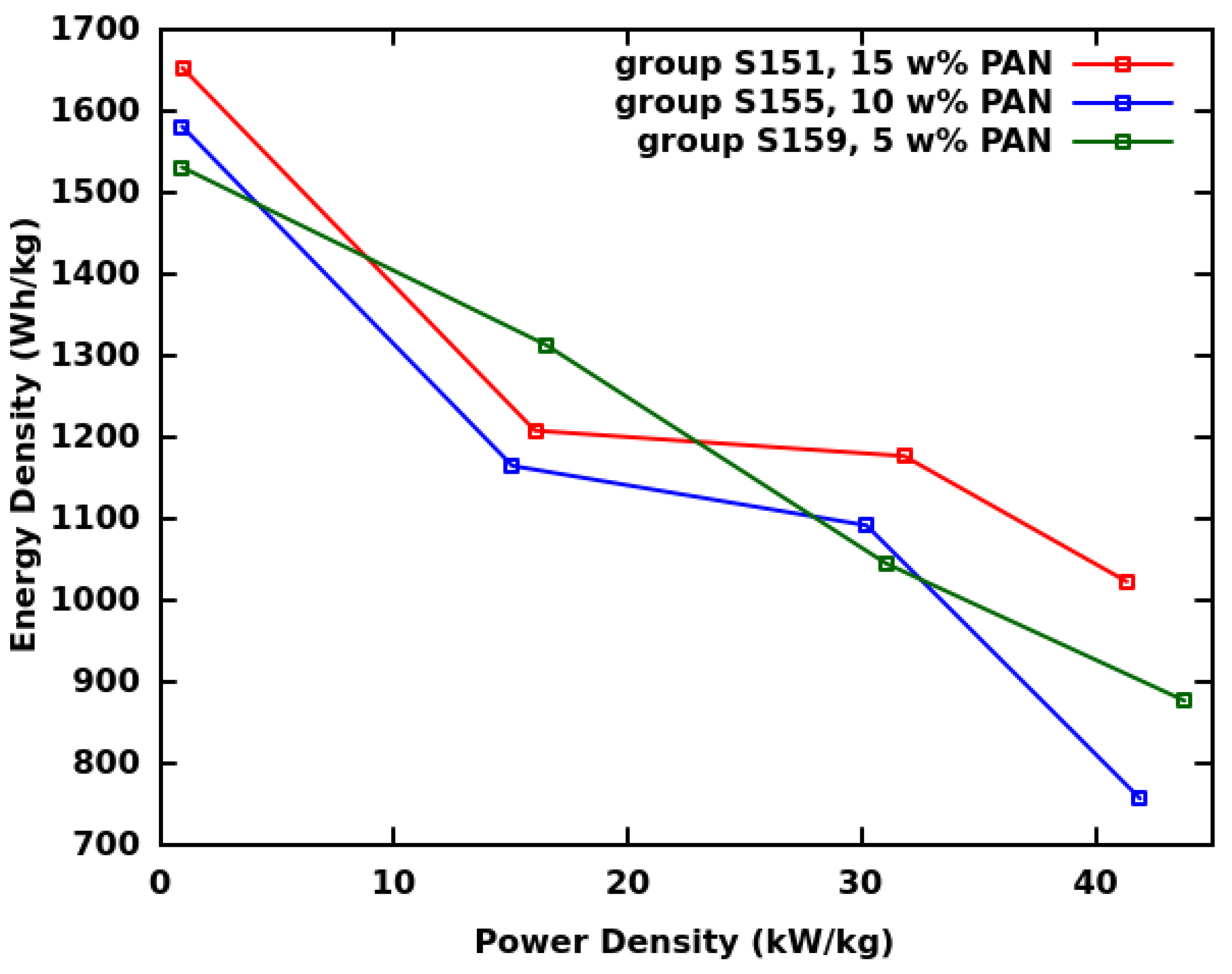
In order to learn about the optimal amount of PAN in the cathode, we explored the performance of the cathodes with 5, 10, and 15 w% PAN, while the combined amount of CF x and PAN was 90 w%. The cathode thickness was 100 μ m (about 1.2 mg/cm 2 CF x loading). The electrolyte was 1 M LiBF 4 in PC:DME:DOL(1:1:1), as usual. The discharge happened at 0.5, 10, 20, and 30 C rates. The voltage cut-off was 1.5 V. The results are shown in Figure 5. They indicate no clear trends. It seems even 5 w% PAN can provide a great performance. It is likely that the spatial distribution of PAN relative to the CF x layers and stacks also matters greatly. For a maximum performance enhancement, it may be advantageous to introduce strands of PAN between the exfoliated layers before the discharge of the battery. In our current slurry-making process, it is more likely that the PAN was mostly attached to the outer surface of the CF x stacks.
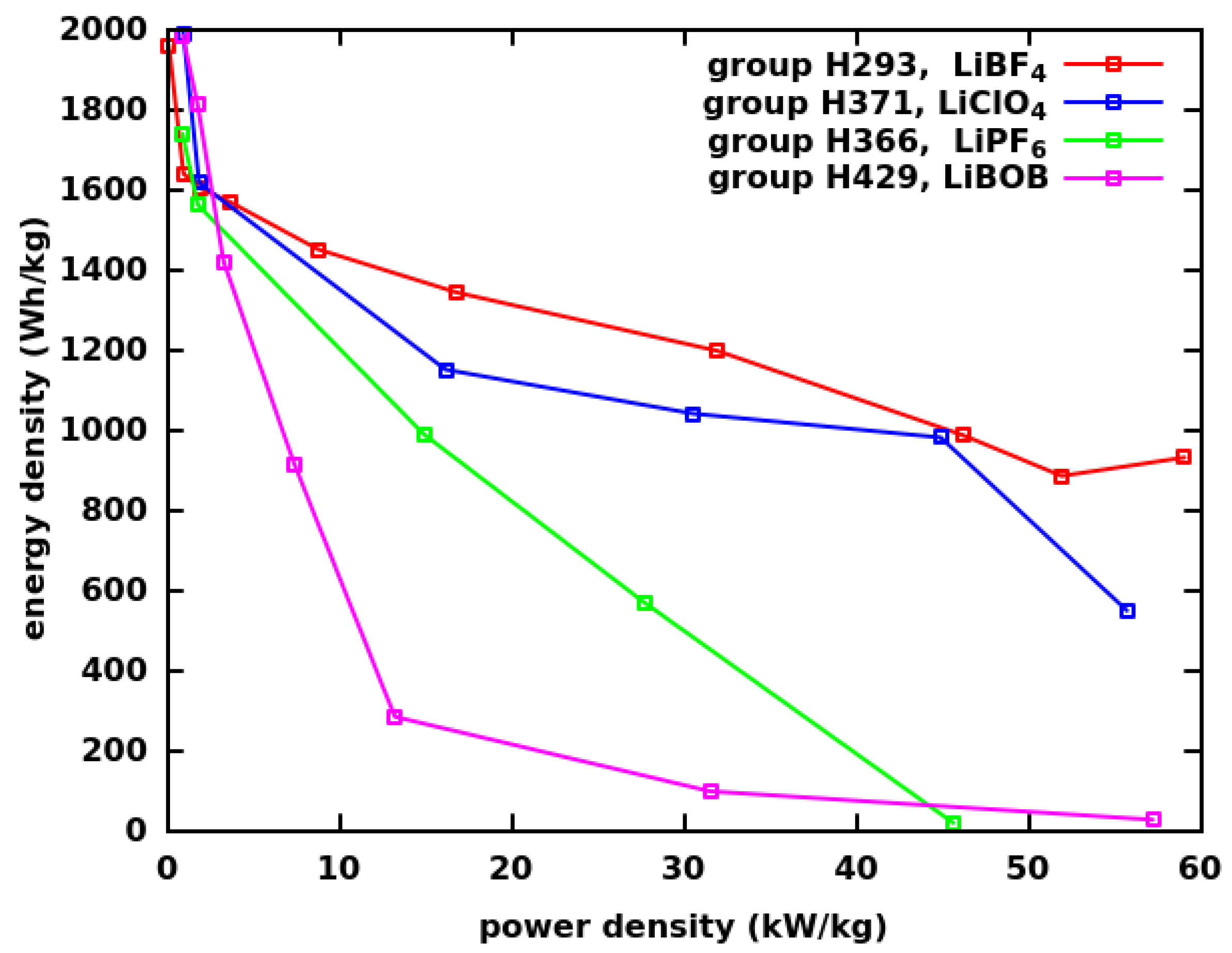
We also explored how the choice of the electrolyte salt influenced the performance of the Li-CF x cells with the PAN binder. There were 1 M solutions of LiBF 4 , LiClO 4 , LiPF 6 , and LiBOB used in PC:DME:DOL(1:1:1). Figure 6 shows the dependence of the energy vs. power density performance on the type of electrolyte. There was a divergent performance at a greater than 5 kW/kg power density: LiBF 4 performed the best, followed relatively closely by LiClO 4 , while LiPF 6 performed much less well, and LiBOB was by far the slowest discharging one.
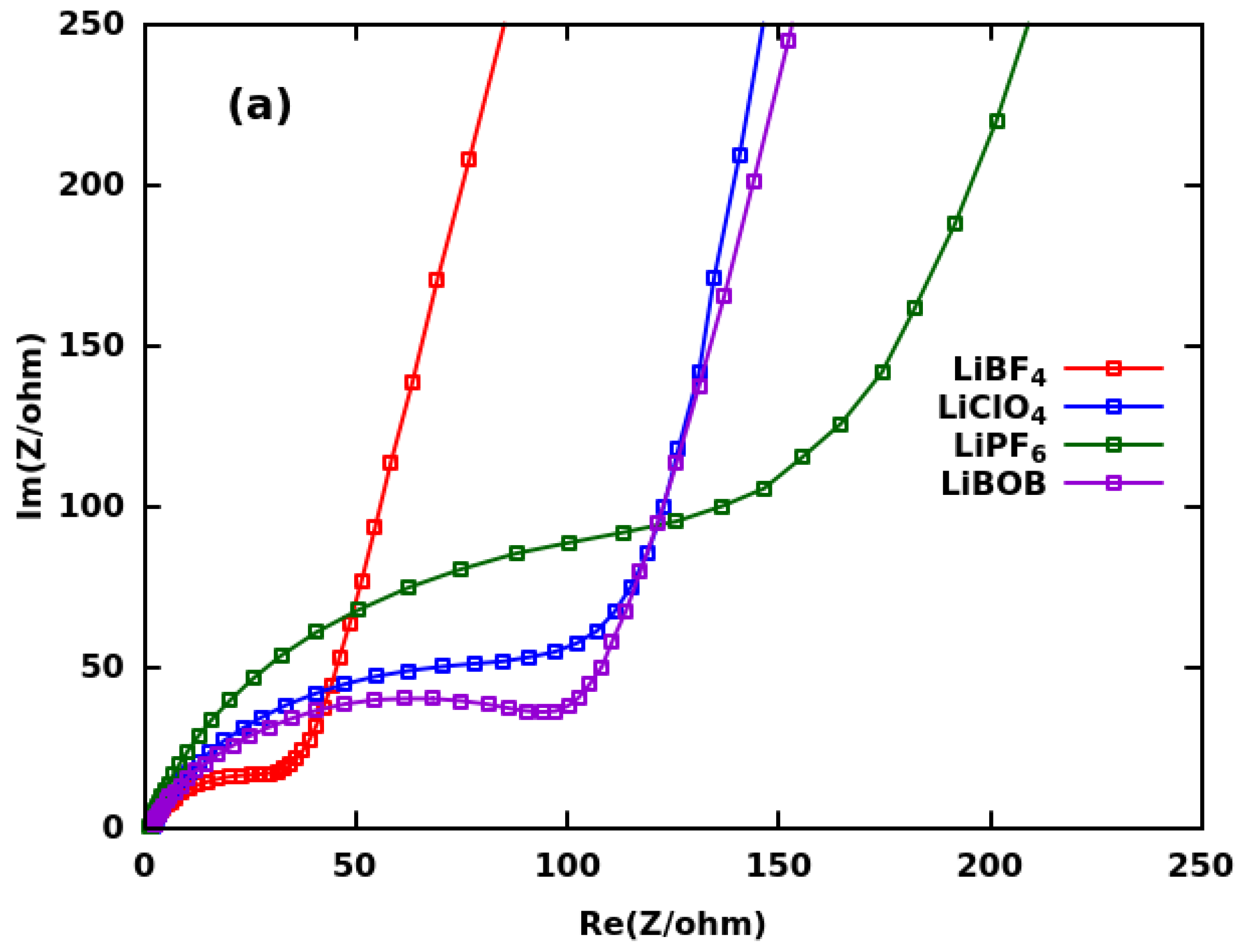
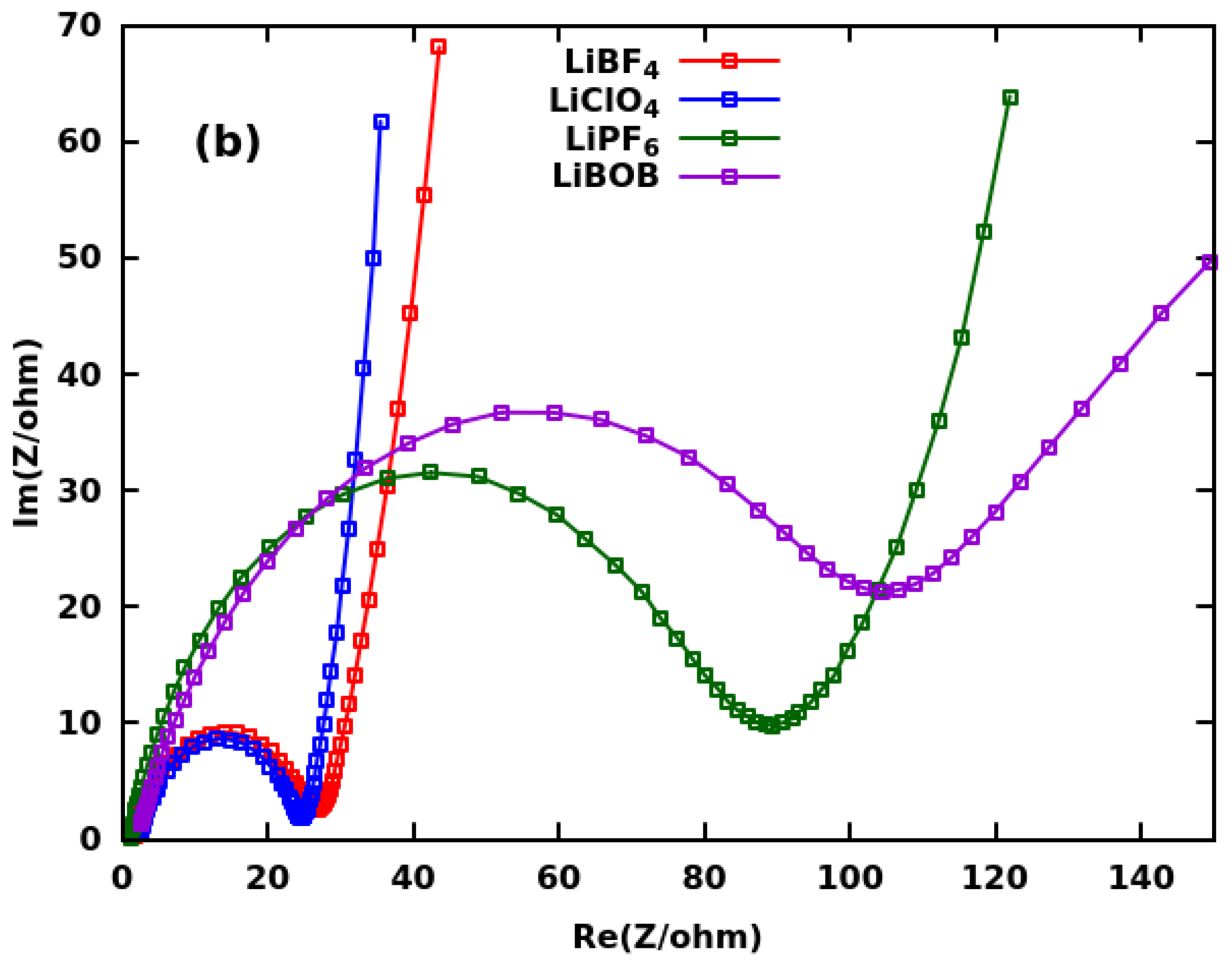
Figure 7 shows the impedances (Z) of the electrolytes before (Panel a) and 1 h after (Panel b) full discharge at a 0.5 C rate. The higher-frequency impedances were close to the origin, while the low-frequency ones were farther away. The slope of the nearly straight section reflects the diffusion coefficient of Li + ions, and the steeper the slope, the higher the ionic conductivity of the electrolyte is. The maximum extent of the semicircle (formed after discharge) on the Re(Z) axis is related to the charge transfer resistance in the system: the smaller the semi-circle, the faster the charge transfer and the higher the power density are. The intercept of the impedance curve with the Re(Z) axis is the bulk resistivity in the system (not discussed here). The charge transfer was fastest in the LiBF 4 and LiClO 4 electrolytes, while it was much slower in the LiPF 6 and LiBOB electrolytes. These observations are in agreement with the measured power densities discussed above.
The semicircles of the impedance data are less complete before discharge than after discharge. The more complete semicircle is typically a sign of the formation of a solid electrolyte interphase (SEI). Interestingly, the charge transfer resistance of the LiClO 4 electrolyte decreased greatly after the SEI formation and became about the same as that of LiBF 4 . This suggests that these latter two electrolytes may form similar SEIs on the anode and their SEIs may be very different from the SEIs of the LiPF 6 and LiBOB electrolytes. References [53,54] suggested that DOL polymerizes in the presence of suitable catalysts, such as Lewis acids, and this polymerization brings advantages for the formation of a stable SEI. Indeed, LiBF 4 can dissociate to LiF and BF 3 , and BF 3 is a Lewis acid, capable of initiating the polymerization of DOL even before discharge. On the other hand, LiClO 4 appears to be able to cause a similar effect during discharge. LiClO 4 is a well-known oxidation agent and a mild Lewis acid. It may release an oxygen radical during the discharge of the battery, while LiClO 3 would form and DOL would polymerize. Similar to the polymerization of DOL, the polymerization of the cyano group side-chains of the PAN can happen through the same effects and contributed to the reduced charge transfer resistance in the presence of the LiBF 4 and LiClO 4 electrolytes. The polymerization of the cyano group side-chains of the PAN resulted in a continuous -C=N--conjugated pi-electron system, which likely improves the electronic conductivity in the system. Furthermore, the strands of the PAN can potentially also serve as ion conduction channels in the cathode based on the well-known property of PAN to form solid (gel) polymer electrolytes with high ionic conductivity [59,60].
Before discharge, the slope of the nearly straight section of the impedance curves was about the same for LiBF 4 , LiClO 4 , and LiBOB, while it was less steep for LiPF 6 . After discharge, the slope of LiClO 4 was the steepest, closely followed by LiBF 4 , while LiPF 6 was even less steep and LiBOB was the least steep one by far. Our current interpretation of these trends is that a fraction of the Li + ions of the electrolyte becomes immobilized during the SEI formation and the Li + concentration in the electrolyte decreases to a varying degree. Based on the trends of the slopes at a rate of 0.5C, the smallest amount of immobilized Li + may occur in LiClO 4 and LiBF 4 , while much more Li + may be immobilized in LiPF 6 and even more in LiBOB. This observation suggests that the anions of the latter two electrolytes may react with the PAN or CFx during discharge and form discharge products that immobilize a fraction of the Li + ions of the electrolyte.
One possible reaction between LiPF 6 and PAN may be based on the chelation of PF 5 by the cyano groups of PAN. Similar chelation reactions of PF 5 through P-N bond and ring formation are well known [61]. In this process, the PF 5 would be derived from the dissociation of LiPF 6 to LiF and PF 5 . This chelation is more likely to happen during discharge when the N atoms of PAN may become more negatively charged and become more nucleophilic.
The immobilization of some Li + in the LiBOB electrolyte may be a result of a similar chelation around the B atom, whereby one oxalate ion is exchanged with two cyanide-ion-like units and Li-oxalate is precipitated. The cyanide-ion-like units may form from the cyano groups of PAN during discharge. The hydrolysis of LiBOB to boric and oxalic acids and their Li salts happens in a similar way with the involvement of hydroxide ions (instead of cyanide) [62].
In principle, the B atom of LiBF 4 can be chelated by PAN in a similar way; however, it seems to happen either to a smaller extent or it does not result in the immobilization of some Li + . The ClO 4 ions cannot be chelated by PAN at all. Perhaps this is reflected by the high ionic conductivity in the batteries with the LiClO 4 electrolyte after discharge.
Further reactions are possible also between the electrolyte and CF x in the presence of PAN or polymerized (in the cyano group side-chains) PAN (PPAN). For example, the oxalate groups of the BOB ions may participate in the Morita–Baylis–Hillman [63] reaction with CF x in the presence of PPAN as a catalyst. A similar reaction was successfully carried out between NaOH and CF x in the presence of a pyridine derivative base (4-Dimethylaminopyridine (DMAP)) and produced densely -OH-functionalized graphene and NaF [55]. PPAN shows structural similarity to the same pyridine derivative base and may play a similar catalytic role in the above-proposed reaction between LiBOB and CF x .
Synchrotron XRD measurements were carried out on the discharged Li-CF x cells with the PAN and PVDF binders in order to investigate the extent of the hypothetical inhibition of LiF crystallization by the PAN binder. The cells were discharged at a 0.5 C rate using 250 μ m-thick cathodes. We found a large amount of crystalline LiF discharge product, as indicated in Figure 8. Our experience was contradictory to that of [37], which found no crystalline LiF in the XRD patterns of the discharged CF x cathodes when a small concentration of BF 3 gas was used in the electrolyte. Therefore, we cannot confirm a similar degree of inhibition of LiF formation when the PAN binder is used. It is, however, possible that the inhibition caused by the PAN binder only slows down the LiF formation on a shorter time scale during discharge, and therefore, it could not be detected by our synchrotron XRD measurements about three weeks after the discharge. Consequently, the inhibition mechanism proposed by Jones and Hossain in [39] may still be valid.
Note also that Jones and Hossain did not mention any electrolyte effects on their proposed inhibition mechanism of the LiF crystallization. Our study points out for the first time in the literature that a combined effect of the binder and the electrolyte can be a simple and robust means of greatly increasing the power density of Li-CF x cells.
Further analysis of the XRD pattern of the discharge products also suggested that it may contain both turbostratic graphite (the broad peak at 7.4 degrees near the (002) reflection of graphite) and a first stage intercalation complex of graphite (the broad peak at 5.9 degrees). Unfortunately, we could not further investigate if these broad peaks might be associated with hard carbon, as suggested in [29].
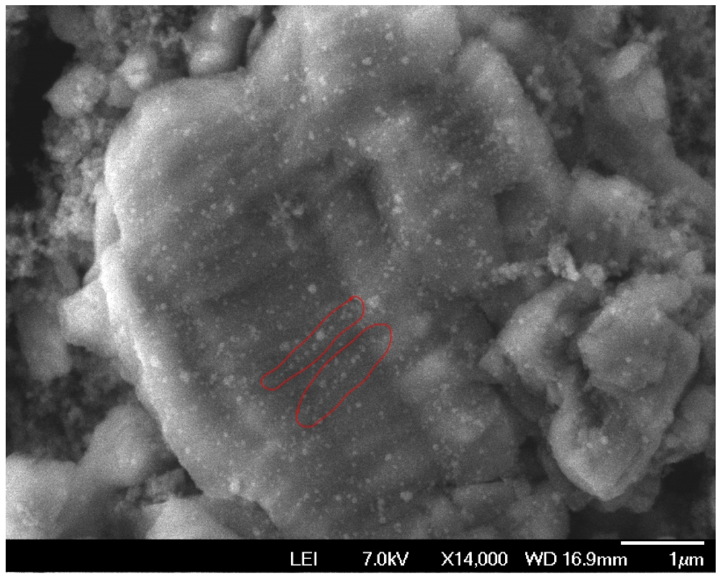
Figure 9 shows the SEM image of a flake of CF x after discharge at a 0.5 C rate. It seems nearby LiF crystals are placed along local strings. This arrangement of LiF crystals may indicate that the strands of PAN serve as nucleation centers for the crystallization of LiF. This observation is in agreement with the prediction of Jones and Hossain that certain polymers bind to LiF crystals and influence their growth [39]. Without PAN, LiF could nucleate at pores, clogging the transport routes of Li + ions. On the one hand, it appears that PVDF or PTFE binders have a smaller complexation affinity to LiF and, therefore, can assist less in its nucleation [64,65]. On the other hand, the ability of PAN to complex and nucleate LiF depends greatly on the electrolyte, as shown above. Further note that, in our experience, the CF x cathodes with the PAN binder appeared to stick better to the Al foil current collectors than with the PVDF binders after the discharge of the battery. This may perhaps indicate a significant difference in the distribution and size of LiF crystals in the presence of different binders.
The morphology of the cathodes after discharge (until the cut-off voltage of 1.5 V is reached) at different C-rates is shown in Figure 10 along with the EDS maps of the F and N atoms. It was assumed that the N atom contribution comes from the PAN only (the residual DMF should be of a negligible amount); therefore, the comparison of the F and N maps is informative about the relative locations of the C-F bonds or LiF crystals and PAN in the cathodes. The distribution of PAN in the cathode seemed to be sufficiently homogeneous before discharge. The same homogeneous distribution of PAN appeared to be present after discharge. It seemed PAN was located near where LiF was located. This observation further suggested that PAN may serve as a nucleation center for LiF crystal growth.
The mechanistic origin of the observed combined binder and electrolyte effects on the power density is not clear yet. Several analogous reactions, however, point toward the electro-catalytic effect of PAN in the given circumstances. As PAN ((CH 2 CH-CN) x ) has cyano (-CN) group side-chains, it is reasonable to assume that these -CN groups would be oxidized by CF x in a similar manner to the oxidation of NaCN by CF x [57]:
x N a C N + C F x x N a F + C + x · C N .
The resulting ·CN radicals mostly dimerize to cyanogen (NC-CN) and then polymerize to paracyanogen (CN) 2 n [57] and, to a lesser extent, may covalently functionalize the graphene sheets [56]. In PAN, an oxidative effect by CF x or by the electrolyte is expected to result in the polymerization of the -CN groups in the side-chains. Such a side-chain polymerization of PAN has been known for long as an effect of heating, and it results in pyridine-type rings and a ladder-type polymer [66].
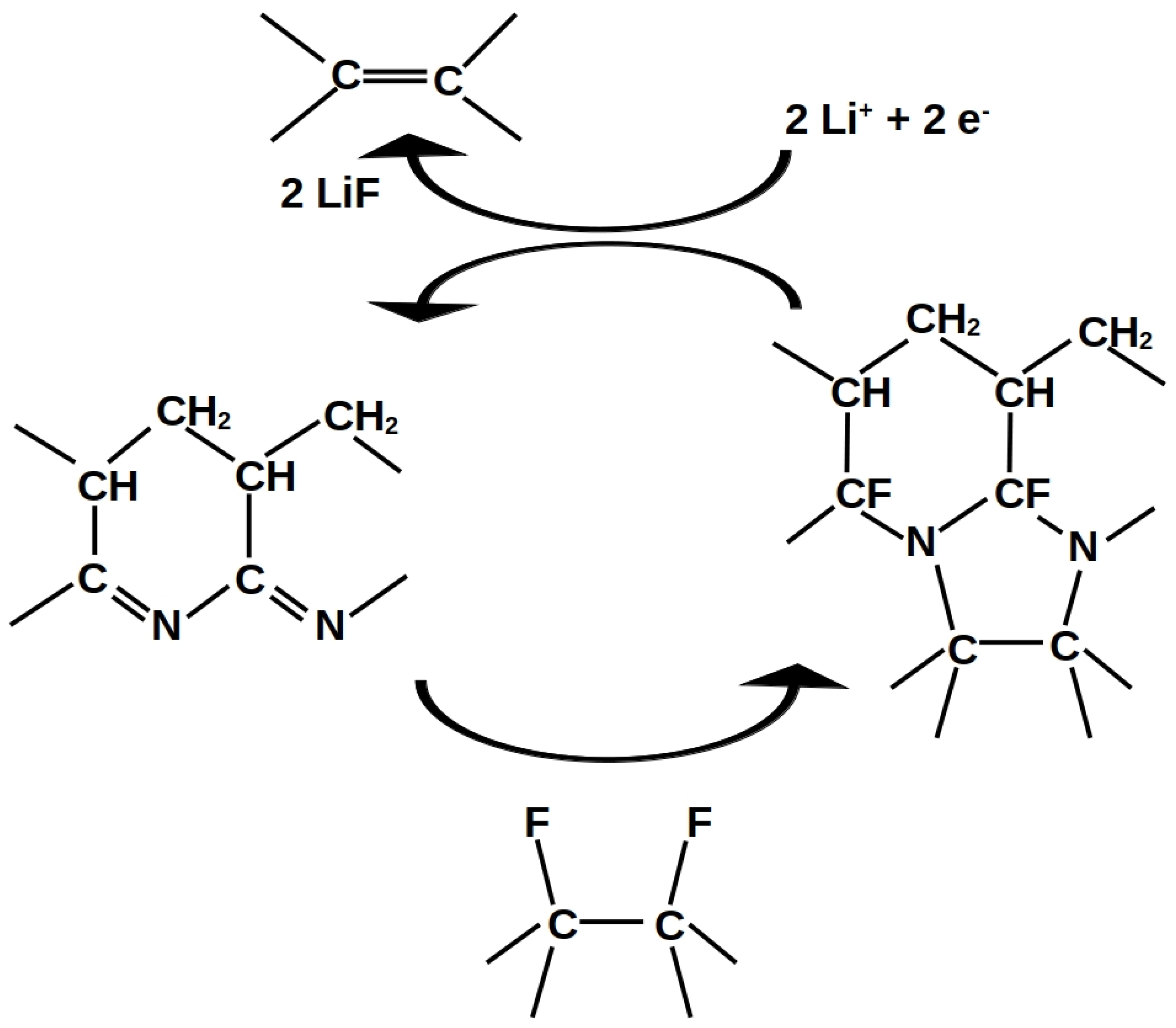
We propose that the side-chain polymerized PAN (PPAN) functions as an electro-catalyst. The catalytic mechanism is depicted in Figure 11. PPAN and CF x form a cyclo-adduct after the nucleophilic attack of PPAN on CF x . This cyclo-adduct is the activated complex of the reaction mechanism. When the battery discharges, the cyclo-adduct is reduced and splits into a residual CF x with a newly formed C=C double-bond and a recycled PPAN, while also LiF is formed.
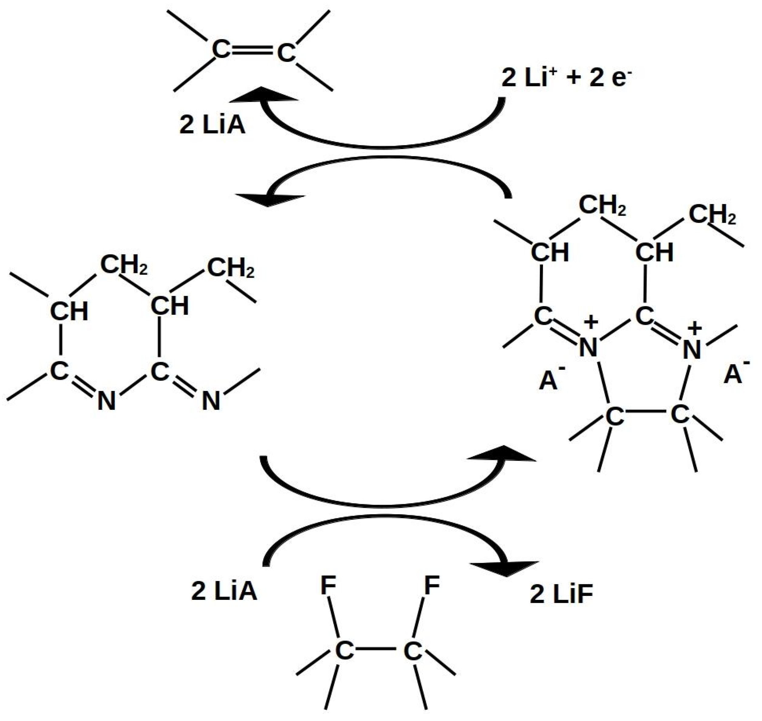
The conjugated -C=N- pi-electron system in the side-chain of PPAN could potentially have a good electronic conductivity if the atoms in the -C=N- chain remain co-planar and sp 2 hybridized even in the activated complex. In this situation, the N atoms of the activated complex would carry a positive charge, which is counterbalanced by an electrolyte anion A , which is not covalently bound to PPAN. The F of the activated complex would precipitate as LiF (extracting Li from the electrolyte) as soon as the activated complex forms. Upon discharge, the activated complex would decompose to PPAN, a new C=C double-bond in the residual CF x , and a restored LiA electrolyte salt. This alternative model is shown in Figure 12. In this situation, the PPAN may play three roles: it is an electro-catalyst and a conductor of electrons and ions to the activated complex.
The catalytic cycle can be active as long as there is a supply of Li and C-F bonds. It seems that PPAN must move on the surface of CF x in order to harvest new C-F bonds. This motion of PPAN can be beneficial for opening up the space between stacked CF x layers. This may be the reason that the catalytic effect works quite well even on non-ultrasonicated CF x . The PAN/PPAN catalyst may be poisoned by certain electrolytes that react with it or with CF x . As discussed above, LiBOB and LiPF 6 appear to be such electrolytes. Since the PVDF and PTFE binders are not reactive with CF x , they cannot provide catalytic effects. Therefore, the proposed catalytic mechanism can account for all the observed phenomena.

4. Conclusions

In the present study, we demonstrated that the choice of the binder and electrolyte plays a crucial role in achieving very high power densities in Li-CF x batteries. As high as a 931 Wh/kg energy density could be achieved at a 59 kW/kg power density in a coin cell when a PAN binder and LiBF 4 electrolyte were used. While a former theoretical proposal by Jones and Hossain predicted tremendous binder effects on the performance of Li-CF x cells [39], assuming that certain binders will inhibit the crystallization of the discharge product LiF, their proposal was not aware of the role of the electrolyte in such effects. The origin of the combined binder and electrolyte effect is not clear yet. Based on the analogy to the proven oxidation of NaCN by CF x , we propose that PAN plays the role of an electro-catalyst in the discharge of CF x as long as an electrolyte is available that is able to reversibly bind to the PAN. The present method allows for a simple and efficient route to very-high-power primary Li-CF x batteries.

Author Contributions

Conceptualization and experiment planning: K.N.; experimental work: H.H., S.R. and K.N.; analysis: K.N., H.H. and L.L.S.; original draft preparation and proposed electro-catalytic mechanism: K.N.; review and editing: K.N., H.H. and L.L.S. All authors have read and agreed to the published version of the manuscript.

Funding

This research was funded in most part by the U.S. National Science Foundation under an STTR Phase I grant to Boron Nitride Power LLC and IIT (Award Number 2109286). Additional private funding was provided by Boron Nitride Power LLC.

Data Availability Statement

The data generated in the present work are available upon request from the authors.

Acknowledgments

This research used the resources (in particular synchrotron XRD facilities) of the Advanced Photon Source, a U.S. Department of Energy (DOE) Office of Science user facility operated for the DOE Office of Science by Argonne National Laboratory under Contract No. DE-AC02-06CH11357.

Conflicts of Interest

The authors declare no conflict of interest. The funders had no role in the design of the study; in the collection, analyses, or interpretation of the data; in the writing of the manuscript; nor in the decision to publish the results.

References

  1. Trahey, L.; Brushett, F.R.; Balsara, N.P.; Ceder, G.; Cheng, L.; Chiang, Y.M.; Hahn, N.T.; Ingram, B.J.; Minteer, S.D.; Moore, J.S.; et al. Energy storage emerging: A perspective from the Joint Center for Energy Storage Research. Proc. Natl. Acad. Sci. USA 2020, 117, 12550–12557. [Google Scholar] [CrossRef]
  2. Yang, X.G.; Liu, T.; Ge, S.; Rountree, E.; Wang, C.Y. Challenges and key requirements of batteries for electric vertical takeoff and landing aircraft. Joule 2021, 5, 1644–1659. [Google Scholar] [CrossRef]
  3. Bills, A.; Sripad, S.; Fredericks, W.L.; Singh, M.; Viswanathan, V. Performance metrics required of next-generation batteries to electrify commercial aircraft. ACS Energy Lett. 2020, 5, 663–668. [Google Scholar] [CrossRef] [Green Version]
  4. Krause, F.; Ruiz, J.; Jones, S.; Brandon, E.; Darcy, E.; Iannello, C.; Bugga, R. Performance of commercial Li-ion cells for future NASA missions and aerospace applications. J. Electrochem. Soc. 2021, 168, 040504. [Google Scholar] [CrossRef]
  5. Krause, F.C.; Jones, J.P.; Jones, S.C.; Pasalic, J.; Billings, K.J.; West, W.C.; Smart, M.C.; Bugga, R.V.; Brandon, E.J.; Destephen, M. High specific energy lithium primary batteries as power sources for deep space exploration. J. Electrochem. Soc. 2018, 165, A2312. [Google Scholar] [CrossRef]
  6. Ndzebet, E.; Destephen, M.; Zhang, D.; Darch, D. High Power and High Rate Li/CFx-MnO2 Pouch Cell Hybrid Technology. In Proceedings of the 48th Power Sources Conference, Denver, CO, USA, 11–14 June 2018; pp. 558–561. [Google Scholar]
  7. Greatbatch, W.; Holmes, C.; Takeuchi, E.; Ebel, S. Lithium/carbon monofluoride (Li/CFx): A new pacemaker battery. Pacing Clin. Electrophysiol. 1996, 19, 1836–1840. [Google Scholar] [CrossRef]
  8. Ruff, O.; Bretschneider, O. Die Reaktionsprodukte der verschiedenen Kohlenstoffformen mit Fluor II (Kohlenstoff-monofluorid). Z. Anorg. Allg. Chem. 1934, 217, 1–18. [Google Scholar] [CrossRef]
  9. Rüdorff, W.; Rüdorff, G. Zur Konstitution des Kohlenstoff-Monofluorids. Z. Anorg. Chem. 1947, 253, 281–296. [Google Scholar] [CrossRef]
  10. Watanabe, N.; Fukuda, M. Primary Cell for Electric Batteries. U.S. Patent 3,536,532, 27 October 1970. [Google Scholar]
  11. Watanabe, K.; Fukuda, M. High Energy Density Battery. U.S. Patent 3,700,502, 24 October 1972. [Google Scholar]
  12. Fukuda, M.; Iijima, T.; Toyoguchi, Y. Active Material for Positive Electrode of Battery. U.S. Patent 4,271,242, 2 June 1981. [Google Scholar]
  13. Sharma, N.; Dubois, M.; Guérin, K.; Pischedda, V.; Radescu, S. Fluorinated (Nano) Carbons: CFx Electrodes and CFx-Based Batteries. Energy Technol. 2021, 9, 2000605. [Google Scholar] [CrossRef]
  14. Ahmad, Y.; Batisse, N.; Chen, X.; Dubois, M. Preparation and Applications of Fluorinated Graphenes. C 2021, 7, 20. [Google Scholar] [CrossRef]
  15. Wang, D.; Wang, G.; Zhang, M.; Cui, Y.; Yu, J.; Shi, S. Composite cathode materials for next-generation lithium fluorinated carbon primary batteries. J. Power Sources 2022, 541, 231716. [Google Scholar] [CrossRef]
  16. Groult, H.; Tressaud, A. Use of inorganic fluorinated materials in lithium batteries and in energy conversion systems. Chem. Commun. 2018, 54, 11375–11382. [Google Scholar] [CrossRef] [PubMed]
  17. Zhang, Q.; Takeuchi, K.J.; Takeuchi, E.S.; Marschilok, A.C. Progress towards high-power Li/CF x batteries: Electrode architectures using carbon nanotubes with CF x. Phys. Chem. Chem. Phys. 2015, 17, 22504–22518. [Google Scholar] [CrossRef] [PubMed]
  18. Chen, P.; Jiang, C.; Jiang, J.; Zou, J.; Ran, Q.; Wang, X.; Niu, X.; Wang, L. Fluorinated Carbons as Rechargeable Li-Ion Battery Cathodes in the Voltage Window of 0.5–4.8 V. ACS Appl. Mater. Interfaces 2021, 13, 30576–30582. [Google Scholar] [CrossRef]
  19. Liu, W.; Li, H.; Xie, J.Y.; Fu, Z.W. Rechargeable room-temperature CF x-sodium battery. ACS Appl. Mater. Interfaces 2014, 6, 2209–2212. [Google Scholar] [CrossRef]
  20. Whittingham, M.S. Mechanism of reduction of the fluorographite cathode. J. Electrochem. Soc. 1975, 122, 526. [Google Scholar] [CrossRef]
  21. Watanabe, N.; Nakajima, T.; Hagiwara, R. Discharge reaction and overpotential of the graphite fluoride cathode in a nonaqueous lithium cell. J. Power Sources 1987, 20, 87–92. [Google Scholar] [CrossRef]
  22. Watanabe, N.; Hagiwara, R.; Nakajima, T.; Touhara, H.; Ueno, K. Solvents effects on electrochemical characteristics of graphite fluoride—lithium batteries. Electrochim. Acta 1982, 27, 1615–1619. [Google Scholar] [CrossRef]
  23. Jang, B.Z.; Liu, C.; Neff, D.; Yu, Z.; Wang, M.C.; Xiong, W.; Zhamu, A. Graphene surface-enabled lithium ion-exchanging cells: Next-generation high-power energy storage devices. Nano Lett. 2011, 11, 3785–3791. [Google Scholar] [CrossRef]
  24. Liu, C.; Zhamu, A.; Neff, D.; Jang, B.Z. Lithium Super-Battery with a Functionalized Nano Graphene Cathode. U.S. Patent 8,795,899, 5 August 2014. [Google Scholar]
  25. Kim, H.; Park, K.Y.; Hong, J.; Kang, K. All-graphene-battery: Bridging the gap between supercapacitors and lithium ion batteries. Sci. Rep. 2014, 4, 5278. [Google Scholar] [CrossRef] [Green Version]
  26. Kim, H.; Park, Y.U.; Park, K.Y.; Lim, H.D.; Hong, J.; Kang, K. Novel transition-metal-free cathode for high energy and power sodium rechargeable batteries. Nano Energy 2014, 4, 97–104. [Google Scholar] [CrossRef]
  27. Kornilov, D.; Penki, T.R.; Cheglakov, A.; Aurbach, D. Li/graphene oxide primary battery system and mechanism. Battery Energy 2022, 1, 20210002. [Google Scholar] [CrossRef]
  28. Zhang, S.S.; Foster, D.; Wolfenstine, J.; Read, J. Electrochemical characteristic and discharge mechanism of a primary Li/CFx cell. J. Power Sources 2009, 187, 233–237. [Google Scholar] [CrossRef]
  29. Sayahpour, B.; Hirsh, H.; Bai, S.; Schorr, N.B.; Lambert, T.N.; Mayer, M.; Bao, W.; Cheng, D.; Zhang, M.; Leung, K.; et al. Revisiting discharge mechanism of CFx as a high energy density cathode material for lithium primary battery. Adv. Energy Mater. 2022, 12, 2103196. [Google Scholar] [CrossRef]
  30. Yazami, R.; Hamwi, A.; Guérin, K.; Ozawa, Y.; Dubois, M.; Giraudet, J.; Masin, F. Fluorinated carbon nanofibres for high energy and high power densities primary lithium batteries. Electrochem. Commun. 2007, 9, 1850–1855. [Google Scholar] [CrossRef]
  31. Lam, P.; Yazami, R. Physical characteristics and rate performance of (CFx) n (0.33 < × < 0.66) in lithium batteries. J. Power Sources 2006, 153, 354–359. [Google Scholar]
  32. Luo, Z.; Wang, X.; Chen, D.; Chang, Q.; Xie, S.; Ma, Z.; Lei, W.; Pan, J.; Pan, Y.; Huang, J. Ultrafast Li/fluorinated graphene primary batteries with high energy density and power density. ACS Appl. Mater. Interfaces 2021, 13, 18809–18820. [Google Scholar] [CrossRef] [PubMed]
  33. Dai, Y.; Cai, S.; Wu, L.; Yang, W.; Xie, J.; Wen, W.; Zheng, J.C.; Zhu, Y. Surface modified CFx cathode material for ultrafast discharge and high energy density. J. Mater. Chem. A 2014, 2, 20896–20901. [Google Scholar] [CrossRef]
  34. Peng, C.; Kong, L.; Li, Y.; Fu, H.; Sun, L.; Feng, Y.; Feng, W. Fluorinated graphene nanoribbons from unzipped single-walled carbon nanotubes for ultrahigh energy density lithium-fluorinated carbon batteries. Sci. China Mater. 2021, 64, 1367–1377. [Google Scholar] [CrossRef]
  35. Jiang, S.; Huang, P.; Lu, J.; Liu, Z. The electrochemical performance of fluorinated ketjenblack as a cathode for lithium/fluorinated carbon batteries. RSC Adv. 2021, 11, 25461–25470. [Google Scholar] [CrossRef]
  36. Wang, K.; Feng, Y.; Kong, L.; Peng, C.; Hu, Y.; Li, W.; Li, Y.; Feng, W. The fluorination of boron-doped graphene for CFx cathode with ultrahigh energy density. Energy Environ. Mater. 2022, e12437. [Google Scholar] [CrossRef]
  37. Li, Q.; Xue, W.; Sun, X.; Yu, X.; Li, H.; Chen, L. Gaseous electrolyte additive BF3 for high-power Li/CFx primary batteries. Energy Storage Mater. 2021, 38, 482–488. [Google Scholar] [CrossRef]
  38. Rangasamy, E.; Li, J.; Sahu, G.; Dudney, N.; Liang, C. Pushing the theoretical limit of Li-CF x batteries: A tale of bifunctional electrolyte. J. Am. Chem. Soc. 2014, 136, 6874–6877. [Google Scholar] [CrossRef] [PubMed]
  39. Jones, S.C.; Hossain, S. Polymer Materials as Binder for a CFx Cathode. U.S. Patent Application 13/010,431, 28 July 2011. [Google Scholar]
  40. Németh, K. Materials design by quantum-chemical and other theoretical/computational means: Applications to energy storage and photoemissive materials. Int. J. Quantum Chem. 2014, 114, 1031–1035. [Google Scholar] [CrossRef] [Green Version]
  41. Zhang, F.; Németh, K.; Bareño, J.; Dogan, F.; Bloom, I.D.; Shaw, L.L. Experimental and theoretical investigations of functionalized boron nitride as electrode materials for Li-ion batteries. RSC Adv. 2016, 6, 27901–27914. [Google Scholar] [CrossRef]
  42. Németh, K. Simultaneous oxygen and boron trifluoride functionalization of hexagonal boron nitride: A designer cathode material for energy storage. Theor. Chem. Accounts 2018, 137, 157. [Google Scholar] [CrossRef] [Green Version]
  43. Németh, K. Radical anion functionalization of two-dimensional materials as a means of engineering simultaneously high electronic and ionic conductivity solids. Nanotechnology 2021, 32, 245709. [Google Scholar] [CrossRef]
  44. Nemeth, K. Functionalized Boron Nitride Materials as Electroactive Species in Electrochemical Energy Storage Devices. U.S. Patent 10,693,137, 23 June 2020. [Google Scholar]
  45. Nemeth, K. Radical Anion Functionalization of Two-Dimensional Materials. U.S. Patent 11,453,596 B2, 7 September 2022. [Google Scholar]
  46. Marshall, J.E.; Zhenova, A.; Roberts, S.; Petchey, T.; Zhu, P.; Dancer, C.E.; McElroy, C.R.; Kendrick, E.; Goodship, V. On the solubility and stability of polyvinylidene fluoride. Polymers 2021, 13, 1354. [Google Scholar] [CrossRef]
  47. Zor, C.; Subaşı, Y.; Haciu, D.; Somer, M.; Afyon, S. Guide to water free lithium bis (oxalate) borate (LiBOB). J. Phys. Chem. C 2021, 125, 11310–11317. [Google Scholar] [CrossRef]
  48. Zhang, M.; Ma, Y.; Zhu, Y.; Che, J.; Xiao, Y. Two-dimensional transparent hydrophobic coating based on liquid-phase exfoliated graphene fluoride. Carbon 2013, 63, 149–156. [Google Scholar] [CrossRef]
  49. Zeng, X.; Peng, Y.; Yu, M.; Lang, H.; Cao, X.; Zou, K. Dynamic sliding enhancement on the friction and adhesion of graphene, graphene oxide, and fluorinated graphene. ACS Appl. Mater. Interfaces 2018, 10, 8214–8224. [Google Scholar] [CrossRef] [PubMed]
  50. Huo, H. High Energy High Power Primary Lithium Batteries with Graphite Fluoride and Functionalized Boron Nitride Cathodes. Master’s Thesis, Illinois Institute of Technology, Chicago, IL, USA, 2022. [Google Scholar]
  51. Tatagari, V.R. A Functionalized 2D Boron Nitride Electrode for Rechargeable Batteries. Master’s Thesis, Illinois Institute of Technology, Chicago, IL, USA, 2021. [Google Scholar]
  52. Li, Y.Y.; Liu, C.; Chen, L.; Wu, X.Z.; Zhou, P.F.; Shen, X.Y.; Zhou, J. Multi-layered fluorinated graphene cathode materials for lithium and sodium primary batteries. Rare Metals 2022, 42, 940–953. [Google Scholar] [CrossRef]
  53. Zhao, Q.; Liu, X.; Zheng, J.; Deng, Y.; Warren, A.; Zhang, Q.; Archer, L. Designing electrolytes with polymerlike glass-forming properties and fast ion transport at low temperatures. Proc. Natl. Acad. Sci. USA 2020, 117, 26053–26060. [Google Scholar] [CrossRef] [PubMed]
  54. Ma, L.; Kim, M.S.; Archer, L.A. Stable artificial solid electrolyte interphases for lithium batteries. Chem. Mater. 2017, 29, 4181–4189. [Google Scholar] [CrossRef]
  55. Bai, L.; Xu, Y.; Liu, A.; Dong, L.; Zhang, K.; Li, W.S.; Zhao, F.G. Unusual graphite fluoride hydrolysis toward unconventional graphene oxide for high-performance supercapacitors and Li-ion batteries. Chem. Eng. J. 2022, 434, 134639. [Google Scholar] [CrossRef]
  56. Bakandritsos, A.; Pykal, M.; Błoński, P.; Jakubec, P.; Chronopoulos, D.D.; Poláková, K.; Georgakilas, V.; Čépe, K.; Tomanec, O.; Ranc, V.; et al. Cyanographene and graphene acid: Emerging derivatives enabling high-yield and selective functionalization of graphene. ACS Nano 2017, 11, 2982–2991. [Google Scholar] [CrossRef] [Green Version]
  57. Siedle, A.; Losovyj, Y.; Stein, B.D.; Pink, M.; Werner-Zwanziger, U. Cyanographite. J. Phys. Chem. C 2022, 126, 3001–3008. [Google Scholar] [CrossRef]
  58. Pang, C.; Ding, F.; Sun, W.; Liu, J.; Hao, M.; Wang, Y.; Liu, X.; Xu, Q. A novel dimethyl sulfoxide/1,3-dioxolane based electrolyte for lithium/carbon fluorides batteries with a high discharge voltage plateau. Electrochim. Acta 2015, 174, 230–237. [Google Scholar] [CrossRef]
  59. Watanabe, M.; Kanba, M.; Nagaoka, K.; Shinohara, I. Ionic conductivity of hybrid films composed of polyacrylonitrile, ethylene carbonate, and LiClO4. J. Polym. Sci. Polym. Phys. Ed. 1983, 21, 939–948. [Google Scholar] [CrossRef]
  60. Chen, H.; Lin, F.; Chen, C. Polyacrylonitrile electrolytes 1. A novel high-conductivity composite polymer electrolyte based on PAN, LiClO4 and a-Al2O3. Solid State Ionics 2002, 150, 327–335. [Google Scholar] [CrossRef]
  61. Wong, C.Y.; Kennepohl, D.K.; Cavell, R.G. Neutral six-coordinate phosphorus. Chem. Rev. 1996, 96, 1917–1952. [Google Scholar] [CrossRef]
  62. Amereller, M.; Multerer, M.; Schreiner, C.; Lodermeyer, J.; Schmid, A.; Barthel, J.; Gores, H.J. Investigation of the hydrolysis of lithium bis [1,2-oxalato (2-)-O, O’] borate (LiBOB) in water and acetonitrile by conductivity and NMR measurements in comparison to some other borates. J. Chem. Eng. Data 2009, 54, 468–471. [Google Scholar] [CrossRef]
  63. Wei, Y.; Shi, M. Recent Advances in Organocatalytic Asymmetric Morita–Baylis–Hillman/aza-Morita–Baylis–Hillman Reactions. Chem. Rev. 2013, 113, 6659–6690. [Google Scholar] [CrossRef] [PubMed]
  64. De Yoreo, J.J.; Vekilov, P.G. Principles of crystal nucleation and growth. Rev. Mineral. Geochem. 2003, 54, 57–93. [Google Scholar] [CrossRef] [Green Version]
  65. Vekilov, P.G. The two-step mechanism of nucleation of crystals in solution. Nanoscale 2010, 2, 2346–2357. [Google Scholar] [CrossRef]
  66. Chung, T.C.; Schlesinger, Y.; Etemad, S.; Macdiarmid, A.; Heeger, A. Optical studies of pyrolyzed polyacrylonitrile. J. Polym. Sci. Polym. Phys. Ed. 1984, 22, 1239–1246. [Google Scholar] [CrossRef]
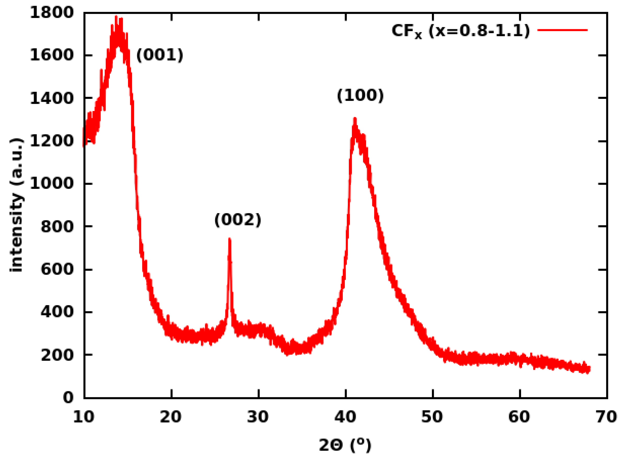
Figure 1. XRD (Cu K α ) pattern of the CF x used in the present study. The presence of some non-fluorinated graphite is indicated by the (002) reflection.
Batteries 09 00268 g001
Figure 2. Gravimetric energy density vs. power density of cells containing cathodes with a 100 μ m layer thickness. Each cell contained a 1 M LiBF 4 electrolyte. The binder was either PAN or PVDF. The detailed composition of the cells can be found in Table 1.
Batteries 09 00268 g002
Figure 3. Voltage vs. capacity density curves at various C rates for CF x batteries in our best-performing cells, which provided the highest energy density at very high power densities (Group H293).
Batteries 09 00268 g003
Figure 4. The dependence of the energy vs. power density performance on the type of binder (PAN or PVDF) and on the thickness of the cathode (100 or 250 μ m). The electrolyte was 1 M LiBF 4 in PC:DME:DOL(1:1:1).
Batteries 09 00268 g004
Figure 5. The energy vs. power density performance of Li-CF x cells with different amounts of PAN in the cathode.
Batteries 09 00268 g005
Figure 6. The dependence of the energy vs. power density performance on the type of electrolyte. The effects of LiBF 4 , LiClO 4 , LiPF 6 , and LiBOB electrolyte salts in PC:DME:DOL(1:1:1) solvent were investigated. The cathode thickness was approximately 100 μ m in all cases.
Batteries 09 00268 g006
Figure 7. Impedance (Z) of Li-CF x cells with 1 M LiBF 4 , LiClO 4 , LiPF 6 , and LiBOB electrolytes before (Panel (a)) and 1 h after (Panel (b)) full discharge at a 0.5 C rate. The electrolyte solvent was PC:DME:DOL(1:1:1).
Batteries 09 00268 g007aBatteries 09 00268 g007b
Figure 8. Synchrotron XRD patterns of the discharged cathodes of Li-CF x cells with PAN and PVDF binders as compared to the patterns of graphite and LiF. The intensities of the LiF pattern are represented on the negative scale for clarity.
Batteries 09 00268 g008
Figure 9. SEM image of a flake of CF x after discharge at a 0.5 C rate. Bright spots indicate LiF crystals. The red encircled area highlights the arrangement of LiF crystals along a string.
Batteries 09 00268 g009
Figure 10. SEM images of CF x cathodes (left panels) and the corresponding EDS maps of F (red) and N (green) atoms (right panels) after discharge at different C rates. The following C rates were studied: 0 (no discharge, Panels (a,b)); 0.5 (c,d); 10 (e,f); 30 (g,h).
Batteries 09 00268 g010
Figure 11. The proposed electro-catalytic action of the PAN binder on CF x during the discharge of the Li-CF x cell. PAN is represented by its side-chain polymerized form (PPAN).
Batteries 09 00268 g011
Figure 12. An alternative version of the proposed electro-catalytic action, which preserves the co-planarity and sp 2 hybridization of the atoms in the -C=N- chain. LiA represents the electrolyte salt.
Batteries 09 00268 g012
Table 1. Cathode composition in different groups of cells.
GroupUltrasonication of CF x ThicknessBinderElectrolyte
IDSolventAdditive( μ m) SaltSolvent
H293EtOH-100PANLiBF 4 PC:DME:DOL
H314EtOH-250PANLiBF 4 PC:DME:DOL
H214EtOH-100PVDFLiBF 4 PC:DME:DOL
H321EtOH-250PVDFLiBF 4 PC:DME:DOL
H366EtOH-100PANLiPF 6 PC:DME:DOL
H371EtOH-100PANLiClO 4 PC:DME:DOL
H429EtOH-100PANLiBOBPC:DME:DOL
H101F 3 B·OEt 2 -100PVDFLiBF 4 PC:DME:DOL
H274F 3 B·OEt 2 LiOX·BF 3 100PANLiBF 4 PC:DME:DOL
H304no ultrasonication100PANLiBF 4 PC:DME:DOL
H179F 3 B·OEt 2 LiOX·BF 3 100PANLiBF 4 DMSO:DOL
H387EtOH-100PVDFLiBF 4 EC:DMC
Disclaimer/Publisher’s Note: The statements, opinions and data contained in all publications are solely those of the individual author(s) and contributor(s) and not of MDPI and/or the editor(s). MDPI and/or the editor(s) disclaim responsibility for any injury to people or property resulting from any ideas, methods, instructions or products referred to in the content.