Article

Effectively Elevating Ceramic Fillers’ Dispersity in Gel Hybrid Electrolyte through Bridge–Linked Construction for High–Performance Lithium Metal Batteries

Key Laboratory of Engineering Dielectric and Applications (Ministry of Education), School of Electrical and Electronic Engineering, Harbin University of Science and Technology, Harbin 150080, China
*
Authors to whom correspondence should be addressed.
Batteries 2023, 9(5), 270; https://doi.org/10.3390/batteries9050270
Submission received: 22 February 2023 / Revised: 24 April 2023 / Accepted: 11 May 2023 / Published: 13 May 2023

Abstract

:
Gel polymer-ceramic hybrid electrolytes (GHEs) have emerged as desirable candidates for preparing high energy density and excellent practicability gel batteries. However, the agglomeration of ceramic particles in polymer matrix leads to a decrease in cycling stability and low mechanical properties of GHEs. Here, we present a feasible method for improving the dispersity of Li0.24La0.59TiO3 (LLTO) nanorods in the polyvinylidenefluoride (PVDF)/poly(propylene carbonate) (PPC) co-blended matrix (K–LLTO/PVDF/PPC) by γ-(2,3-epoxypropoxy)propytrimethoxysilane (KH560) surface treatment. The as-prepared GHE with 10% K–LLTO filler (10% GHE) exhibits a high ionic conductivity (3.01 mS cm−1) and an appropriate lithium-ion transference number (0.55). The Li|10% GHE|Li symmetric cell shows an exceptional lithium stripping-plating lifetime of > 2000 h at 0.1 mA cm−2. The assembled LiFePO4 (LFP)|10% GHE|Li full cells show satisfactory cycling stability in the 2.5–4.2 V electrochemical window by recovering 84% of the initial capacity at 2 C over 500 cycles. The uniformly dispersed K–LLTO within the polymer matrix is ascribed to the formation of a bridge-linked network via Si–O–Ti bonds between KH560 and LLTO, and plenty of hydrogen bonds within the polymer matrix. This modification method provides a feasible strategy for fabricating GHEs with good repeatability, which may easily adapt to the high requirements of commercial production.

1. Introduction

Lithium-ion batteries (LIBs) have permeated our lives in miscellaneous consumer electronic equipment, power grids, and other domains for several decades [1,2]. Driven by the ever-increasing demand for high energy density, however, the theoretical bottleneck of LIBs essentially limits their further development [3,4,5]. The lithium metal batteries (LMBs) with the metallic “holy grail” Li0 as the anode have been revived, aiming to boost the next-generation rechargeable batteries which endow electric vehicles with long driving mileage [6]. However, several challenges of LMBs, including the notorious lithium dendrite growth and severe parasitic side reactions between liquid electrolytes and the lithium anode, must be solved prior to the implementation of practical applications [7]. To this end, replacing organic liquid electrolytes with solid-state electrolytes (SSEs) has been regarded as a promising method, stimulating extensive interests and investigations of SSEs due to their high safety and superior electrochemical properties, which are expected to adapt to modern energy storage devices [8].
Commercial membranes (e.g., polypropylene, polyethylene, etc.) exhibit possibilities for cost-effectiveness, tight attachment with electrodes, and mature preparation techniques for their applications in LMBs. However, challenges such as poor wettability and the tendency to shrink at high temperatures limit the wide explorations of commercial membranes in LMBs. Solid polymer electrolytes (SPEs), on the other hand, have been widely studied due to their plasticity, safety, flexibility, light weight, and reliability. Nevertheless, the ionic conductivity of SPEs is generally very low at room temperature, excluding the possibility of their operation at ambient conditions [9]. Therefore, developing versatile gel polymer electrolytes (GPEs) is highly necessary because of their salient features, including superior ionic conductivity and lower electrolyte/electrode interfacial resistance, rendering GPEs one of the most promising electrolyte systems for the implementation of safer LMBs.
Among various types of polymer materials, polyvinylidene fluoride (PVDF), poly(vinylidene fluoride-co-hexafluoropropylene) (PVDF–HFP), polyacrylonitrile (PAN), and polymethyl methacrylate (PMMA) have been widely studied, which is mainly attributed to their excellent mechanical strength, high-temperature resistance, and anti-corrosion ability [10,11]. It is known that PVDF is well received and applied in modern industrial production due to its advantages of good mechanical property and interfacial stability [10,12]. The polar C–F groups with high electronegativity of PVDF–based electrolytes allow the high dissociation ability of lithium salts [13]. It is revealed that the introduction of PPC is an effective approach to alleviate the swelling of PVDF–based GPEs [14]. PPC always exists as a rigid and brittle polymer at room temperature and has a high melting point of 180 °C [15]. Whilst PPC is a green and degradable material that is regarded as a desirable polymer component because of its high ionic conductivity and Li-ion transference number at room temperature. C=O with its high electronegativity allows the dissociation of Li salts and interactions with PF6 anions [16]. The Li-ion transport ability mainly lies with the intercoupling of oxygen atoms in polymer chains and Li+. However, the segmental relaxation of the polymer backbone at ambient temperature is significantly slower than the highly active segment motion at high temperatures, which leads to the low ionic conductivity of polymer substrates.
It has been demonstrated that gel hybrid electrolytes (GHEs) combining Li+–conductive ceramic filler with polymer matrix would reduce the crystalline regions via disorganizing the regular arrangement of polymer chains and providing extra Li+ diffusion pathways through polymer/ceramic interphases to concomitantly achieve higher ionic conductivity [17]. Furthermore, the mechanical strength and electrochemical stability window of GHEs are generally enhanced compared to the GPEs. Perovskite-type ceramic such as Li3xLa2/3−xTiO3 (LLTO) features superior ionic conductivity and high stability in the air atmosphere, rendering it a promising ceramic filler for GHEs [18,19]. However, it is known that Ti4+ is easily reduced by lithium metal, resulting in the formation of mixed ionic-electronic conducting interphases, leading to an increase in interfacial resistance, volume change, and even fracture of the bulk electrolyte [20]. In this regard, incorporating ceramics with high corrosion resistance and superior oxidative resistance, and a polymer matrix with high electrochemical stability can effectively address the above-mentioned issues [21,22,23].
However, a critical yet remaining challenge of GHEs lies in the agglomeration of inorganic particles, which leads not only to reduced volume fraction of conductive interphases, interrupted percolation network, and consequently lower ionic conductivity, but also to undesirable repeatability, which is a majordrawback for mass production [24]. The agglomeration mainly originates from the high surface energy of ceramic fillers as well as their poor compatibility with polymer matrix [25]. Additionally, the morphology (particle size, shape, arrangement, etc.) of ceramic fillers is revealed to play an important role in improving the homogeneous distribution within GHEs [26]. In contrast to the nanoscale inorganic fillers, particles with a large diameter can lead to a worse dispersity [27]. In this regard, many efforts have been devoted to addressing this problem, chiefly in terms of modulating the size, shape and arrangement of ceramic fillers [28,29], surface modification [30,31,32], and ceramic in-situ synthesis [33,34]. Zhang et al. devised an innovative γ-aminopropyltriethoxysilane (KH550) surface-modified (Ba0.6Sr0.4)TiO3 (BST), i.e., KH550@BST. The formation of hydrogen bonds among PVDF and KH550@BST particles provides intermolecular forces to facilitate the uniform dispersion of inorganic fillers [35].
Herein, we report a feasible method (Scheme 1) to elevate the dispersity of inorganic LLTO nanorods fillers (average diameter of ≈600 nm) in PVDF/PPC co-blended polymer matrix, via using the γ-(2,3-epoxypropoxy)propytrimethoxysilane (KH560) silane coupling agent to construct surface linkages between the ceramic fillers and the polymer matrix. The LLTO nanorods, with a large aspect ratio, provide a higher polymer-ceramic interphase area facilitating the continuous Li-ion transportation [36,37]. Incorporating 10% K–LLTO as the filler (10% GHE), the enhanced filler dispersity compared to the GHE containing 10% of LLTO filler contributes to a high ionic conductivity of 3.01 mS cm−1 and an ideal Li-ion transference number of 0.55 at room temperature, the latter is expected to be beneficial for alleviating concentration polarization inside the cell. Moreover, excellent flexibility, mechanical strength and thermal stability are demonstrated. Furthermore, the 10% GHE obtains higher oxidation resistance, the highest electrolyte uptake ratio, and a high critical current density (CCD) of 0.9 mA cm−2. As a result, the Li|10% GHE|Li symmetric cells achieve extremely stable cycling performance and the LiFePO4|10% GHE|Li (LFP|10% GHE|Li) full cells achieve a good cycling life. Taken together, this shows that this surface grafting strategy is promising for fabricating high-performance GHEs, moreover, exhibits the potential to be adapted to other hybrid solid-state electrolyte systems.

2. Materials and Methods

2.1. Chemicals

Lithium nitrite (LiNO3, Mw = 68.94), lanthanum nitrite hexahydrate (La(NO3)3·6H2O, Mw = 433.01), titanium butoxide (Ti(OC4H9)4, Mw = 340.32), PVDF (Mw = 530,000), poly(vinylpyrrolidone) (PVP) (Mw = 1,300,000), PPC (Mw = 50,000), H2O2 (Mw = 34.01), acetate (Mw = 60.05), N,N-dimethylformamide (DMF) (Mw = 73.09), and KH560 (Mw = 236.34) were supplied from Aladdin Chem. Co. Shanghai. China. All the chemicals mentioned above were used directly without further treatment.

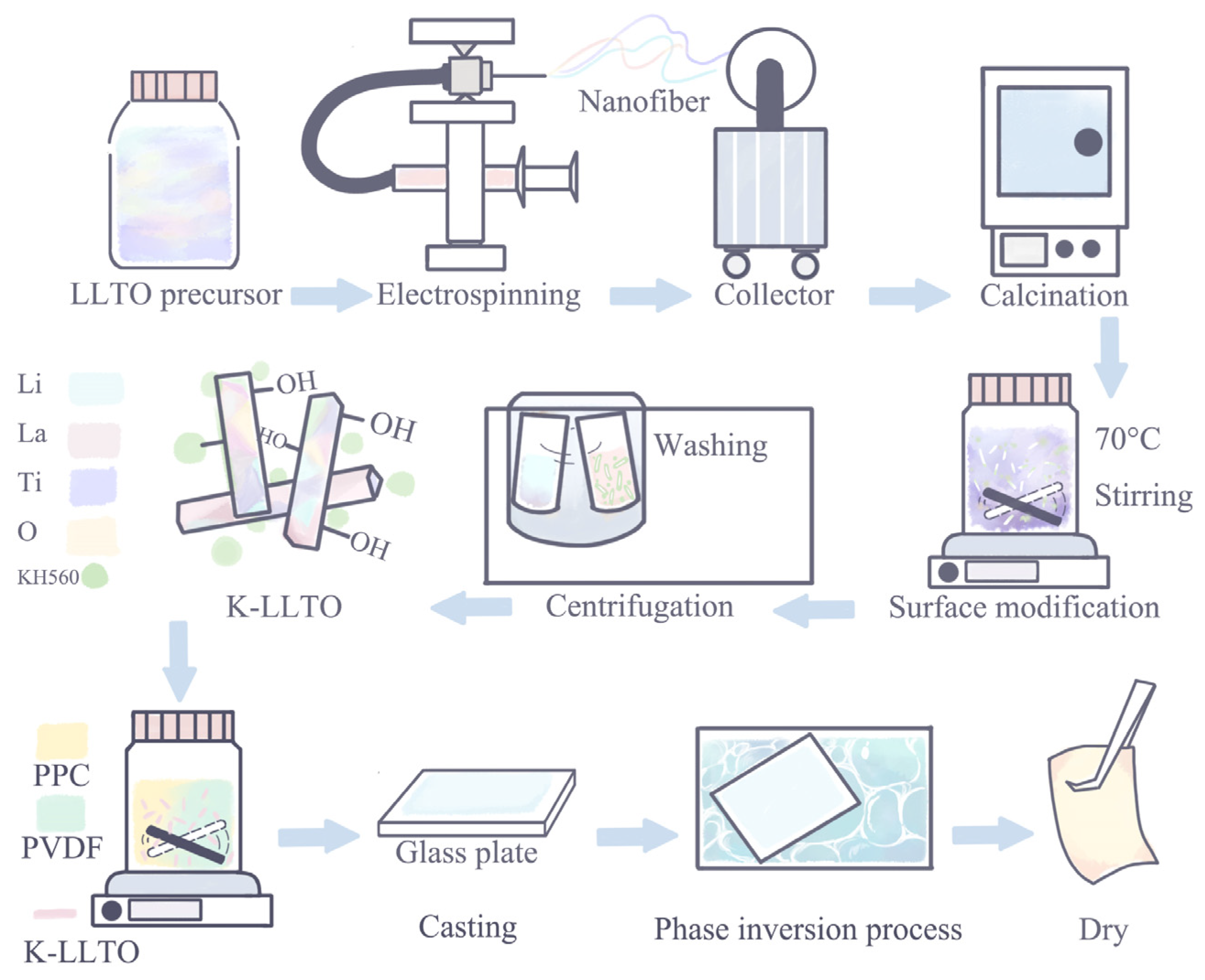
2.2. Synthesis of LLTO Nanorods

LLTO precursor nanofibers were prepared via the electrospinning method. Firstly, LiNO3 (0.2256 g) and La(NO3)3·6H2O (2.4024 g) were dissolved in a DMF solvent (16 mL) under stirring treatment. Acetate acid (4 mL) was subsequently added under continuous stirring for 30 min. Then, Ti(OC4H9)4 (3.372 g) was added and mixed thoroughly with the above solution. Finally, PVP (1.8 g) was added to the above solution to increase the precursor’s viscosity, and it was stirred for 12 h. All the above processes were undergone at room temperature. Subsequently, the homogenous solution was loaded into a syringe (20 mL) and then subjected to an electrospinning procedure (voltage: 19 kV; feeding rate: 1 mL h−1; distance between the collector and spinneret holder: 16 cm). Finally, the LLTO nanorods were obtained by heating the LLTO precursor nanofiber mat at 1000 °C for 6 h in air with a heating rate of 5 °C min−1.

2.3. Synthesis of K–LLTO Nanorods

The LLTO nanorods were dispersed in an aqueous solution of H2O2. The suspension was then violently stirred at 70 °C for 2 h. Then, KH560 was addedin a weight equivalent to 8% of the mass of LLTO nanorodsto the above solution and stirred for 2 h. Aiming to wash the residual KH560, the suspension was centrifuged at a 10,000× g rotation speed 3 times (10 min) using ethyl alcohol and then dried in a vacuum oven at 60 °C for 15 h. Finally, the modified K–LLTO nanorods were obtained.

2.4. Fabrication of K–LLTO Doped Dry GHEs (dGHEs) and GHEs

K–LLTO nanorods were dispersed in 10 mL of DMF; afterwards, PVDF (0.8 g) and PPC (0.2 g) were also added under mechanical stirring at 60 °C and sonication until a uniform mixture suspension was gained. The weight ratio of K–LLTO to the total mass of K–LLTO + PVDF + PPC was fixed at 0%, 5%, 10% and 15%, respectively. The corresponding dry membranes are denoted as dGPE, 5% dGHE, 10% dGHE, and 15% dGHE, respectively. The proportion of polymer matrix was to the same as that in the work carried out by Huang et al. [16]. The obtained homogenous ivory-white suspension was then cast onto a glass plate which was subsequently immersed in deionized water. The membrane was dried directly at 60 °C in an oven for 20 h. The milky porous x% dGHE (x = 5, 10, and 15) membranes were finally gained. The GHE membranes were obtained by immersing dGHE membranes with 25 μL of liquid electrolyte (i.e., 1 M lithium hexafluorophosphate (LiPF6) in ethylene carbonate: diethyl carbonate: ethyl methyl carbonate (EC:DEC:EMC) = 1:1:1, vol%). The GHEs with different K–LLTO doping ratios are noted as GPE, 5% GHE, 10% GHE and 15% GHE, respectively.

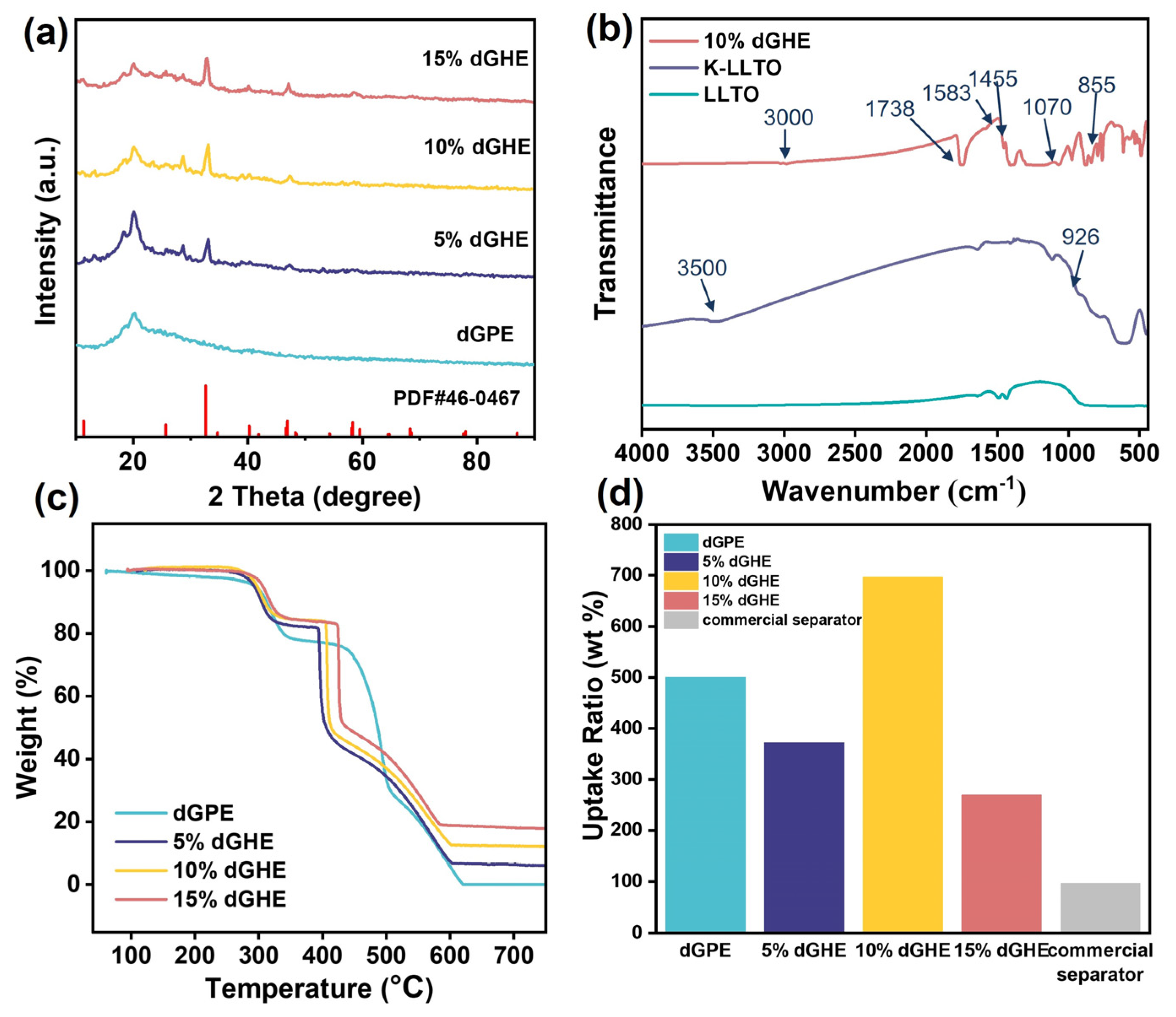
2.5. Characterization

The morphology and phase identification were examined by scanning electron microscope (SEM, SUN8020, Hitachi Corporation of Japan) and X-ray diffractometer (XRD; Rigaku D/MAX 2550/PC) with a Cu Kα radiation source (λ = 1.5406 Å). Thermogravimetric analysis (TGA, TGA–Q500 instrument) was conducted in nitrogen (N2) atmosphere with a heating rate of 10 °C min−1. Fourier transform infrared spectroscopy (FT–IR) analysis was recorded with a PerkinElmer spectrometer (L1600400 spectrum Two DTGS). The electrolyte uptake (EU%) of GHEs was determined by immersing the prepared dGHEs in commercial liquid electrolytes. The results were calculated via the following Equation (1):
E U % = m 2     m 1 m 1   ×   100 % ,
where m 1 is the weight of dGHEs (g), and m 2 is the weight of GHEs absorbed with liquid electrolyte (g).

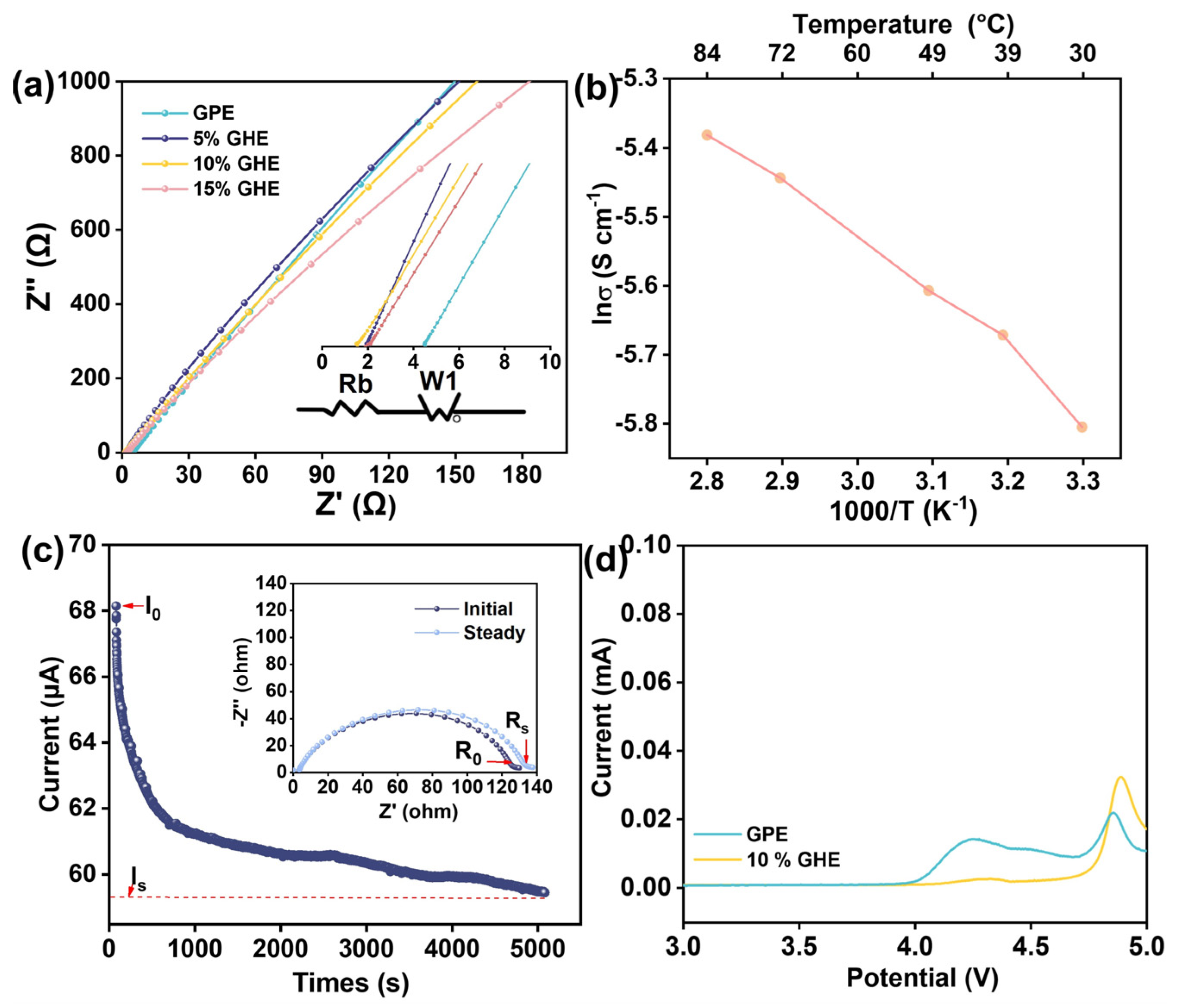
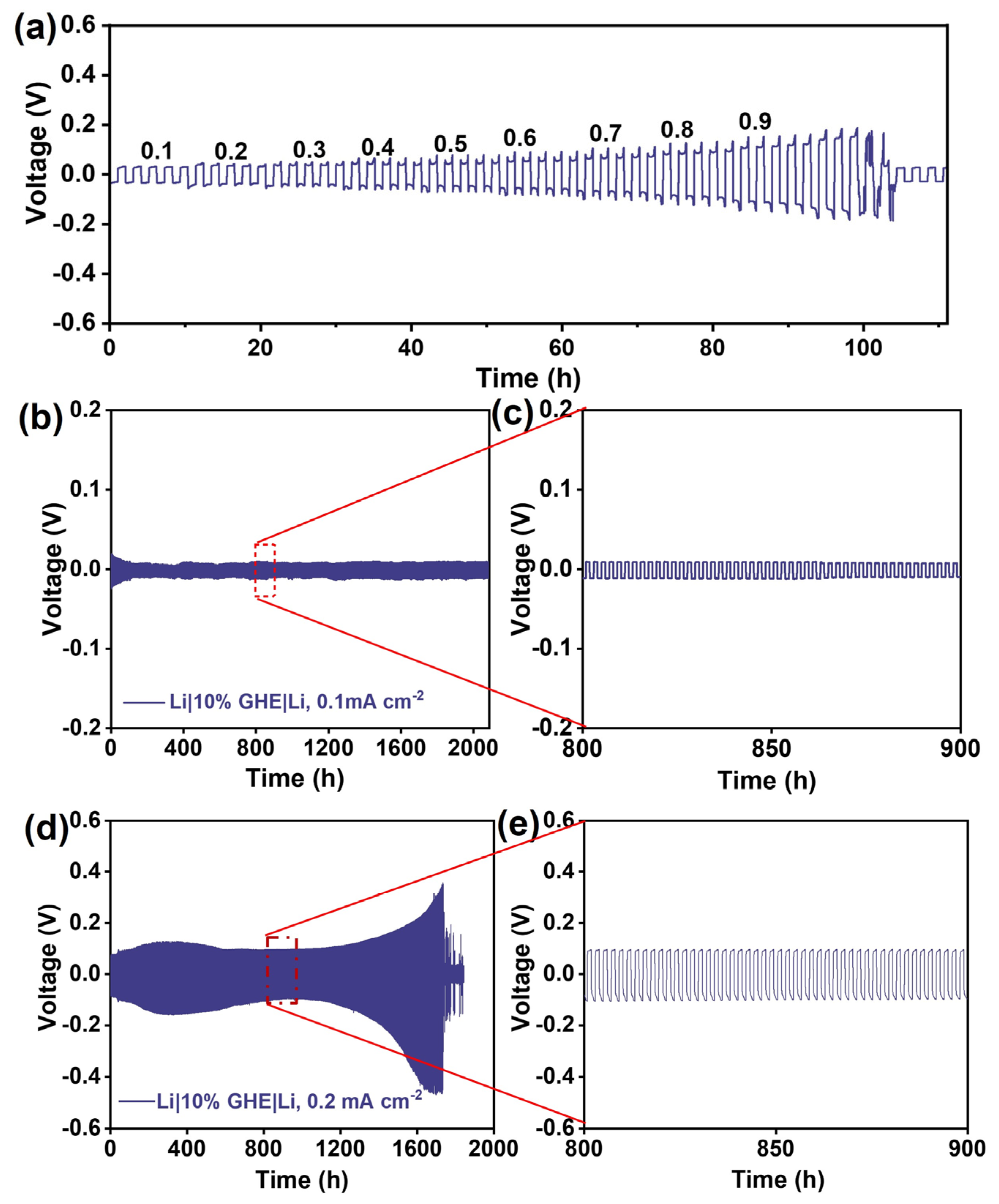
2.6. Electrochemical Measurements and Analysis

The evaluation of the oxidation stability of GHEs was conducted in Li|GHE|SS (SS: stainless steel) cells in a voltage range of 3.0–5.0 V. The cyclic voltammetry (CV) test was carried out in LFP|GHE|Li full cell (voltage: 2.5–4.2 V; 0.05 mV s−1). Electrochemical impedance spectroscopy (EIS; Princeton P4000; amplitude: 10 mV; frequency: 0.1 Hz–1 MHz) was performed to determine the ionic conductivity ( σ ) of GHEs (Equation (2)) in SS|GHE|SS cells and the resistance of LFP|GHE|Li full cells (before cycling and after 100 cycles). The Arrhenius plots were obtained by recording the EIS results at different temperatures using a controlled chamber (DHG–9030A) from 30 °C to 84 °C. Five cells were measured to obtain an average value. The determination of lithium-ion transference number ( t + ) was performed in Li|GHE|Li cells using the Evans-Vincent-Bruce method (Equation (3)).
σ = L A   R
where L is the thickness of the GHE (cm), A is the dimension of the SS electrode (cm2), and R is the resistance which was obtained from the real axis in the Nyquist plot (Ω).
t + = I s Δ V     I 0 R 0 I 0 Δ V     I s R s ,
where Δ V is the voltage polarization applied (mV), I s and R s are the steady−state current (μA) and impedance (Ω), and I0 and R0 are the initial current and resistance, respectively.
The lithium stripping-plating performance (0.1 mA cm−2) and the determination of critical current density (CCD; 0.1–0.9 mA cm−2) were measured in Li|GHE|Li symmetric cells. All the electrochemical performances including rate capability and cycling stability were carried out in LFP|GHE|Li cells. For fabricating the LFP cathode electrodes, LFP, super P and PVDF were mixed in a ratio of 8:1:1 together with a certain amount of n-methyl-2-pyrrolidone (NMP) solvent for 10 h. The as-prepared slurry was cast on Al foil using a lab-scale doctor blade technique. The as-prepared wet electrode was then dried in a vacuum oven at 70 °C for 12 h. Electrode disks with a diameter of 12 mm were cut. The active material loading of LFP was about 2.8–3.2 mg cm−2. All the electrochemical performances were recorded via a battery test system (Neware CT–4000 battery test system) at 25 °C. All types of cells were assembled in an Ar-filled glove box (H2O and O2 < 0.1 ppm).

3. Results and Discussion

Figure 1a,b shows the morphology of the as-prepared LLTO precursor nanofiber mat fabricated via electrospinning. The diameter of major fibers is about 200–400 nm. After the sintering procedure, the LLTO nanorods are obtained (Figure 1c), which have a large aspect ratio and the size is mainly about 400–600 nm. Figure 1d shows the XRD pattern of the LLTO nanorods. The diffraction peaks are in accordance with the standard card (PDF#046–0467), suggesting the high purity of LLTO nanorods. The characteristic peaks observed at 11.4°, 25.8°, 32.6°, 34.8°, 40.3°, 41.9°, 46.9°, 48.5°, 54.3°, 58.3°, 64.5°, 68.3°, 77.6° and 87.0° can be well indexed to the (001), (101), (102), (111), (112), (103), (004), (211), (212), (105), (220), (310) and (224) lattice planes of the crystalline Li0.24La0.59TiO3, respectively.
The grafted mechanism diagram is presented in Figure 1e. It has been revealed that the silane coupling agents, such as KH560 and γ-methyl-propylene trimethoxysilane (KH570), tend to hydrolyze and then polymerize with active groups (i.e., –OH) on the surface of inorganic oxide materials to complete the grafting process [30,31]. Several practical studies reported by Mallakpour et al. and Zhang et al., etc., [30,35] have succeeded in establishing active connections between polymer and ceramic fillers via Ti–O–Ti, Si–O, C–O, and C–H bonds, etc. Herein, the surface of LLTO nanorods is effectively hydroxylated during the intensive stirring step in H2O2 solution at 70 °C. The subsequent introduction of KH560 into the above suspension leads to two reactions. First, the –OH groups anchoring on the LLTO nanorods’ surface react with the –OH groups produced by the hydrolyzed –CH3 groups of KH560 via dehydration condensation. Finally, the Ti–O–Si bonds are formed linking the ceramic LLTO nanorods and KH560. As evidenced in Figure 1g, the EDS mapping of a selected region (Figure 1f) indicates a uniform distribution of Si element on the K–LLTO nanorods, suggesting the successful surface modification of ceramic filler. See more details of the comparative SEM, EDS mappings and EDS spectra of LLTO and K–LLTO in Figure S1–S4 (Supporting Information). Second, the epoxy groups located at the end tail of KH560 are ring-opened, concomitantly with the formation of hydroxyl groups under basic conditions. These hydroxyl groups can essentially form hydrogen bonds with PVDF. Consequently, the simultaneous influence of hydrogen bonds, Ti–O–Si, and –OH groups promotes bridge-like links allowing for more intimate, uniform and continuous three-dimensional (3D) interactions between polymer and ceramic fillers, which can significantly facilitate the dispersity of ceramic fillers within polymer matrix [38].
XRD patterns of the dGPE, 5% dGHE, 10% dGHE and 15% dGHE are comparatively shown in Figure 2a. According to the turquoise blue curve, peaks at around 18.3° and 20.6° are characteristic diffraction peaks of PVDF [13,22]. The characteristic peak of PPC can be observed at 20° [39]. For the dGHE membranes, these peaks’ intensity shows a decreasing trend along with increasing inorganic filler doping amount from 5% to 15%, an indication of decreased crystallinity. Hence, it is demonstrated that the addition of K–LLTO nanorods promotes the irregular arrangement of polymer chains. It is worthwhile to mention that the diffraction peaks of K–LLTO are identical to those of pure LLTO, indicating that the surface modification does not change its crystalline structure.
To examine whether the KH560 is grafted on the surface of LLTO, FT–IR measurement of 10% dGHE is carried out. As shown in Figure 2b, compared with the pure LLTO, two new peaks at about 3500 and 926 cm−1 appear in the spectrum of K–LLTO, corresponding to the –OH and Si–O–Ti bonds, respectively. The outcome proves the successful connection between the terminal of KH560 and the LLTO surface. In addition, evident in the FT–IR spectrum of 10% dGHE, the bending vibration of –CH2 and the deformation vibration of –CF2 in PVDF can be assigned to 1404 cm−1 and 841 cm−1 [22]. The formation of C=C is located at 1583 cm−1. For PPC, characteristic peaks such as C–H stretching (e.g., CH2 and CH3), C=O stretching, C–O–C and amorphous areas occur at 3000 cm−1, 1738 cm−1, 1071 cm−1 and 855 cm−1, respectively [16,40]. Furthermore, the intensity of –OH peaks of 10% dGHE is weakened when blending the PVDF/PPC polymer matrix with K–LLTO nanorods. This can be explained by the reactions of –OH groups of K–LLTO surface with –CF2 of PVDF chains to form hydrogen bonds. The grafted K–LLTO nanorods possess excellent distribution feature and endow with lower crystallinity of polymer matrix. The latter conclusion is in a good agreement with the XRD results.
In the next step, TGA analysis is conducted to evaluate the thermal stability of various dGHEs. As displayed in Figure 2c, the heat decomposition processes are manifested in three stages. The first stage (at 287 °C) is associated with the decomposition of PPC (~17% weight loss). The initial thermal decomposition of PVDF in 10% dGHE with ceramic fillers occurs at approximately 400 °C and lasts until ~420 °C due to the breakage of bonds with low bonding energy, accounting for a weight loss of 33%. Notably, the dGPE exhibits a higher decomposition temperature of PVDF, which is in accordance with the higher crystallinity revealed in Figure 2a. Afterwards, the second-stage thermal decomposition of PVDF due to the breakage of C–C main chains ends at ~600 °C with a weight loss of 38%. Compared to the K–LLTO-free dGPE, the TGA curves of various K–LLTO-doped dGHEs demonstrate decreased thermal stability, which may be related to the increased amorphous regions after incorporating ceramic fillers. The comparison in the aspect of electrolyte uptake of various dGHEs is shown in Figure 2d, where 10% dGHE shows the highest EU% of 696% than other dGHEs, following the order of commercial Celgard separator (96%) < 15% dGHE (269%) < 5% dGHE (372%) < dGPE (500%) < 10% dGHE (696%).
The morphology of the 10% dGHE is representatively studied as shown in Figure 3a,e. In combination with the EDS mappings of Ti, La, and O (Figure 3b–d), the homogenous dispersion of K–LLTO nanorods within the PVDF/PPC polymer matrix is evidenced at high magnification. The surface and cross-sectional SEM micrographs of 10% dGHE shown in Figure 3e–h display an apparent porous structure with homogenous dispersion of K–LLTO fillers. The cross-section SEM images (Figure 3f–h) of 10% dGHE reflect that the unique hierarchical porous structure is mainly ascribed to the phase inversion method. The DMF molecules rapidly dissolved in deionized water and left dense holes with small sizes on the membrane surface, where an exchange of non-solvent and solvent components occurred. Subsequently, the typical hierarchical porous structure is formed. K–LLTO nanorods can be observed in the continuous cellular holes. In view of the dispersion of K–LLTO nanorods on the surface/cross-section of 10% dGHE and EDS mapping images, it can be concluded that the K–LLTO nanorods with bridge-linked constructions in the polymer matrix are uniformly distributed throughout the hybrid electrolyte membrane. In sharp contrast, without surface modification treatment, the SEM image of the LLTO-doped dGHE membrane displays severe agglomeration of LLTO nanorods (Figure 3i).
Before adding the inorganic fillers, the pure dGPE is transparent and flexible. It is shown that the color of the K–LLTO-doped dGHE changes to milky white and meanwhile the flexibility is well retained (Figure 3j). The mechanical strength test of dGPE and 10% dGHE membranes has been examined via subjecting both membranes to gradually increased weights starting from 50 g (with an interval of 50 g). When the weight reaches 300 g, the dGPE fractures immediately. On the other hand, the 10% dGHE is able to delay the onset fracture weight from 300 g to 350 g. (Figure S5 and Video S1, Supporting Information).
There exist numerous interfacial regions between the K–LLTO nanorods and the PVDF/PPC polymer matrix. According to the aforementioned XRD results, the introduction of K–LLTO reduces the crystallinity of dGHEs. Along with the increasing dopants ratios, the dominant Li+ transport pathways change from amorphous phases to interfacial penetration regions and ceramic conductors [26]. It is known that the perovskite-type LLTO nanorods with high surface energy are more thermodynamical to accumulate to reduce the surface energy. A high doping ratio above the threshold can result in high interfacial impedance and low Li+ conductivity. Hence, the optimal filler doping ratio and the uniform distribution of fillers are deemed crucial for GHE systems. Therefore, herein, the lithium-ion conductivity of various GHE membranes is calculated based on the Nyquist plots (Figure 4a). The ionic conductivities of GPE, 5% GHE, 10% GHE and 15% GHE at room temperature are measured to be 1.15, 2.74, 3.27 and 2.52 mS cm−1, respectively. Overall, the introduction of K–LLTO provides a higher ionic conductivity than that of the K–LLTO-free GPE. The optimal doping amount is revealed to be 10%. The temperature-dependent ionic conductivity of 10% GHE in the temperature range of 30 to 84 °C is further studied in Figure 4b, from which we clearly observe that the Li+ transportation within 10% GHE follows an Arrhenius behavior. To name a few, the ionic conductivities at 30 °C, 50 °C and 84 °C are 3.01, 3.67 and 4.6 mS cm−1, respectively. Such high ionic conductivities are mainly ascribed to the homogeneity between ceramic nanorods/polymer substrates and the higher electrolyte uptake ratio. The ultrahigh ionic conductivity of 10% GHE is mainly attributed to a collection of factors, including liquid electrolyte regions absorbed in a porous polymer network, uniform and intimate interface between the ion-conductive ceramic and polymer matrix thanks to the high surface area, a large aspect ratio of nanorods and the H-bonds between polymer and K–LLTO, and the Li+ conducting K–LLTO nanorods, building enormous fast Li-ion transportation channels. Additionally, it is revealed that the hydrogen bonds can facilitate the interactions with polar groups and meanwhile increase the irregular regions of polymers, yielding a higher concentration of free Li+ [25]. In this comprehensive system, the segmental dehydrofluorinated PVDF chains favor the dissociation of LiPF6 via Lewis acid-based reactions, verified by the C=C (1583 cm−1) from the FT–IR spectrum (Figure 2b), which leads to the complexing of free Li+ and polymer chains and dopant surfaces.
The Li-ion transference number of 10% GHE is determined to be 0.55 at room temperature according to Equation (3) (Figure 4c), which is higher than that of the pure PVDF–based GPE (0.36) [41]. Notably, a high Li-ion transference number can induce decreased concentration polarization, enable uniform Li deposition and potentially the formation of steady SEI. The LSV of GPE and 10% GHE were also measured at room temperature (Figure 4d). The anodic stability of 10% GHE is elevated from 4.1 V (GPE) to 4.75 V, which implies the synergistic effect between K–LLTO and the polymer matrix contributing to higher resistance against oxidation at high voltage.
To analyze the compatibility of the 10% GHE with Li metal, the Li|10% GHE|Li symmetrical cells were assembled. The CCD profile is presented in Figure 5a, which demonstrates that the maximum current density reaches as high as 0.9 mA cm−2. Furthermore, the Li|10% GHE|Li cell indicates high stability against Li metal, as revealed by an extremely stable lithium stripping-plating performance over 2000 h at 0.1 mA cm−2 (Figure 5b,c). The overpotential is stabilized at approximately 10 mV. When increasing the current density to 0.2 mA cm−2 (Figure 5d,e), the Li|10% GHE|Li cell still allows for a relatively steady cycling performance of 1400 h, after which a strong growth of overpotential is observed. At approximately 1750 h, the cell becomes short-circuited. The outcome suggests that the uniform distribution of K–LLTO ceramic fillers induced inter-connected structures in the polymer substrate achieves homogenous transportation of Li+ flux.
To observe the feasibility of GHE in practical cells, LFP|10% GHE|Li, LFP|PVDF/PPC/LLTO|Li and LFP|GPE|Li cells were tested at room temperature. Figure 6a shows the Nyquist plot of LFP|10% GHE|Li cell at an open circuit voltage (OCV) state (in rose pink). The overall interfacial impedance is estimated to be 230 Ω. After 100 cycles at 1 C, only less than 50 Ω of resistance increase is observed, indicating high interfacial stability in the full cell. The initial four cycles of CV curves (Figure 6b) show typical Fe2+/Fe3+ oxidation/reduction couple locating at 3.2 V and 2.7 V. It is clearly seen that these four CV curves exhibit nearly identical profiles, implying exceptional reversibility and very minor polarization within the cell.
The cycling performance of LFP|10% GHE|Li cells are subsequently evaluated in the voltage range from 2.5 to 4.2 V. The selected charge-discharge curves (i.e., 1st, 10th, 30th, 50th, and 100th cycle) of LFP|10% GHE|Li cell at 1 C are shown in Figure 6c. The curves show high reversibility, while the polarization voltage is only 185.4 mV. After 100 cycles, the discharge capacity of LFP|10% GHE|Li still maintains at 142.9 mAh g−1, achieving a capacity retention ratio of 99.2%. In contrast, the LFP|GPE|Li full cell not only delivers much less discharge capacity but also shows strong capacity fluctuation over 100 cycles (Figure 6d). At 2 C (Figure 6e), the LFP|10% GHE|Li full cell delivers a discharge capacity of 112.3 mAh g−1, higher than that of the LFP|GPE|Li cell (103.8 mAh g−1). The discharge capacity of LFP|10% GHE|Li decreases to 92.51 mAh g−1 after 500 cycles, achieving a capacity retention ratio of 83.5%. By contrast, a rapid capacity decay is evidenced in the LFP|GPE|Li cell for the first 50 cycles, although there is a gradual capacity recovery afterwards, the cell’s cycling lifetime ends at around 350 cycles. To investigate the impact of “bridge-linker” between LLTO ceramic filler and polymer matrix, the cycling performance of LFP|PVDF/PPC/LLTO|Li full cells are also conducted. With respect to the LFP|10% GHE|Li full cells, less capacities are delivered at 1 C (135.1 mAh g−1) and 2 C (119.8 mAh g−1) for LFP|PVDF/PPC/LLTO|Li full cells.
The evaluation of rate capacity of LFP|10% GHE|Li, LFP|PVDF/PPC/LLTO|Li and LFP|GPE|Li full cells is shown in Figure 6f. At current densities of 0.1, 0.2, 0.5, 1, 2 and 5 C, the LFP|10% GHE|Li cell delivers capacities of 162.0, 159.0, 151.6, 141.6, 123.5 and 96.8 mAh g−1, respectively. The LFP|PVDF/PPC/LLTO|Li full cell shows capacities of 154.8 (0.1 C), 152.0 (0.2 C), 144.4 (0.5 C), 135.2 (1 C), 120.7 (2 C) and 90.4 mAh g−1 (5 C), respectively. In contrast, the LFP|GPE|Li full cell exhibits always less capacity at all C-rates, i.e., 141.2 (0.1 C), 138.8 (0.2 C), 130.7 (0.5 C), 121.6 (1 C), 98.5 (2 C) and 85.4 (5 C) mAh g−1, respectively. The outcome underlines that the GHE with a 10% doping ratio can deliver higher capacity, better rate capability, and more stable long-term cycling performance. The best rate capability and cycling stability of 10% GHE-based cells reveals the effectiveness of adopting ceramic K–LLTO filler as bridge-linkers in GHEs.
Such a superior electrochemical performance of the LFP|10% GHE|Li is mainly ascribed to the uniform ceramic filler dispersion and the intimate connection of polymer matrix and K–LLTO nanorods, providing essentially enormous Li+ transport pathways.
Going a step further, an LED panel was lit by a LFP|10% GHE|Li pouch cell (GHE: ≈2.6 cm in length, ≈4 cm in width), and the photograph is presented in Figure 6g. The pouch cell delivers a steady voltage output for the constant light source. This result verifies the good compatibility of the designed GHE core structure and the internal component of the pouch cell. The anti-deformation and film self-supporting ability of 10% GHE membrane enable practical applications in batteries verified by the well-maintained integrity of the core separator.

4. Conclusions

In this paper, we demonstrate the feasibility of using the PVDF/PPC/K–LLTO-based gel-ceramic hybrid electrolyte for high-performance lithium metal batteries, after solving the common challenge of inorganic fillers’ agglomeration in polymer matrix to ensure the uniform Li+ flux upon repeated cycling. The introduction of an optimal number of KH560 surface-modified LLTO nanorods within PVDF/PPC co-blended polymer matrix enhances synergistic effects among the components of the hybrid electrolyte. In detail, in the bond-connected network of GHE, more Li+ migration channels exist along the interphase of polymers/ceramic nanorods, liquid electrolyte areas, and amorphous regions in the as-prepared gel membranes, in contrast to the K–LLTO-free and LLTO-containing counterpart. Apart from the formation of intimate connection between polymer and ceramic filler, the plentiful hydrogen bonds and Si–O–Ti linkages also endow the higher dissociation of Li salts and improve the concentration of free Li+ in the GHEs, which eventually deliver a superior ionic conductivity (3.01 mS cm−1) and Li-ion transference number (0.55). The micro-pores membrane increases the electrolyte uptake ratio and thus improves the interfacial wettability. When operating at 1 C, the LFP|10% GHE|Li full cell delivers an initial discharge capacity of 142.9 mAh g−1 with a high capacity retention ratio of 99.2% after 100 cycles. At 2 C, the full cell is capable of maintaining 84% of its initial capacity upon 500 cycles. The Li|10% GHE|Li full cell enables an excellent steady cyclic lifespan of about 2000 h at 0.1 mA cm−2. Overall, the various contributions arising from the homogenous ceramic fillers and bridge-linked micro-structures of GHE result in the high performance of LMBs.

Supplementary Materials

The following supporting information can be downloaded at: https://www.mdpi.com/article/10.3390/batteries9050270/s1, Figure S1: EDS results and spectrum of LLTO nanorods; Figure S2: EDS results and spectrum of K–LLTO nanorods; Figure S3: SEM image and corresponding EDS mappings of LLTO nanorods; Figure S4: SEM image and corresponding EDS mappings of K–LLTO nanorods; Figure S5: comparative mechanical strength tests of GPE and 10% dGHE; Video S1: the mechanical strength of GPE and 10% dGHE.

Author Contributions

Conceptualization, M.C. and Z.C.; methodology, W.L.; software, Z.Y.; validation, M.C., Z.C. and W.L.; investigation, Z.Y.; data curation, Z.Y.; writing—original draft preparation, M.C. and W.L.; writing—review and editing, Z.C. and Y.L.; supervision, Y.W. (Yang Wang) and Y.W. (Yixin Wu); project administration, Z.C.; funding acquisition, M.C. and Z.C. All authors have read and agreed to the published version of the manuscript.

Funding

This work is supported by the National Natural Science Foundation of China (Grant No. 52122702), National Natural Science Foundation of China (Grant No. 52277215), Natural Science Foundation of Heilongjiang Province of China (No. JQ2021E005).

Data Availability Statement

The data presented in this study are available on request from the corresponding author. The data are not publicly available due to confidentiality.

Conflicts of Interest

The authors declare no conflict of interest.

References

  1. Liang, H.P.; Zarrabeitia, M.; Chen, Z.; Jovanovic, S.; Merz, S.; Granwehr, J.; Passerini, S.; Bresser, D. Polysiloxane-based single-ion conducting polymer blend electrolyte comprising small-molecule organic carbonates for high-energy and high-power lithium-metal batteries. Adv. Energy Mater. 2022, 12, 2200013. [Google Scholar] [CrossRef]
  2. Xu, L.; Lu, Y.; Zhao, C.Z.; Yuan, H.; Zhu, G.L.; Hou, L.P.; Zhang, Q.; Huang, J.Q. Toward the scale-up of solid-state lithium metal batteries: The gaps between lab-level cells and practical large-format batteries. Adv. Energy Mater. 2020, 11, 2002360. [Google Scholar] [CrossRef]
  3. Li, M.; Lu, J.; Chen, Z.; Amine, K. 30 years of lithium-ion batteries. Adv. Mater. 2018, 30, 1800561. [Google Scholar] [CrossRef] [PubMed]
  4. Goodenough, J.B.; Kim, Y. Challenges for Rechargeable Li Batteries. Chem. Mater. 2009, 22, 587–603. [Google Scholar] [CrossRef]
  5. Chen, Z.; Kim, G.-T.; Wang, Z.; Bresser, D.; Qin, B.; Geiger, D.; Kaiser, U.; Wang, X.; Shen, Z.X.; Passerini, S. 4-V flexible all-solid-state lithium polymer batteries. Nano Energy 2019, 64, 103986. [Google Scholar] [CrossRef]
  6. Placke, T.; Kloepsch, R.; Dühnen, S.; Winter, M. Lithium ion, lithium metal, and alternative rechargeable battery technologies: The odyssey for high energy density. J. Solid State Electrochem. 2017, 21, 1939–1964. [Google Scholar] [CrossRef]
  7. Kalhoff, J.; Eshetu, G.G.; Bresser, D.; Passerini, S. Safer electrolytes for lithium-ion batteries: State of the art and perspectives. ChemSusChem 2015, 8, 2154–2175. [Google Scholar] [CrossRef] [PubMed]
  8. Zheng, Y.; Yao, Y.; Ou, J.; Li, M.; Luo, D.; Dou, H.; Li, Z.; Amine, K.; Yu, A.; Chen, Z. A review of composite solid-state electrolytes for lithium batteries: Fundamentals, key materials and advanced structures. Chem. Soc. Rev. 2020, 49, 8790–8839. [Google Scholar] [CrossRef]
  9. Zhu, M.; Wu, J.; Wang, Y.; Song, M.; Long, L.; Siyal, S.H.; Yang, X.; Sui, G. Recent advances in gel polymer electrolyte for high-performance lithium batteries. J. Energy Chem. 2018, 37, 126–142. [Google Scholar] [CrossRef]
  10. Wu, Y.; Li, Y.; Wang, Y.; Liu, Q.; Chen, Q.; Chen, M. Advances and prospects of PVDF based polymer electrolytes. J. Energy Chem. 2022, 64, 62–84. [Google Scholar] [CrossRef]
  11. Wang, S.-H.; Lin, Y.-Y.; Teng, C.-Y.; Chen, Y.-M.; Kuo, P.-L.; Lee, Y.-L.; Hsieh, C.-T.; Teng, H. Immobilization of Anions on Polymer Matrices for Gel Electrolytes with High Conductivity and Stability in Lithium Ion Batteries. ACS Appl. Mater. Interfaces 2016, 8, 14776–14787. [Google Scholar] [CrossRef] [PubMed]
  12. Chen, L.; Qiu, X.; Bai, Z.; Fan, L.-Z. Enhancing interfacial stability in solid-state lithium batteries with polymer/garnet solid electrolyte and composite cathode framework. J. Energy Chem. 2021, 52, 210–217. [Google Scholar] [CrossRef]
  13. Martins, P.; Lopes, A.C.; Lanceros-Mendez, S. Electroactive phases of poly(vinylidene fluoride): Determination, processing and applications. Prog. Polym. Sci. 2014, 39, 683–706. [Google Scholar] [CrossRef]
  14. Zhang, J.; Yang, J.; Dong, T.; Zhang, M.; Chai, J.; Dong, S.; Wu, T.; Zhou, X.; Cui, G. Aliphatic Polycarbonate-Based Solid-State Polymer Electrolytes for Advanced Lithium Batteries: Advances and Perspective. Small 2018, 14, e1800821. [Google Scholar] [CrossRef] [PubMed]
  15. Li, L.; Deng, Y.; Chen, G. Status and prospect of garnet/polymer solid composite electrolytes for all-solid-state lithium batteries. J. Energy Chem. 2020, 50, 154–177. [Google Scholar] [CrossRef]
  16. Huang, X.; Zeng, S.; Liu, J.; He, T.; Sun, L.; Xu, D.; Yu, X.; Luo, Y.; Zhou, W.; Wu, J. High-performance electrospun poly(vinylidene fluoride)/poly(propylene carbonate) gel polymer electrolyte for lithium-ion batteries. J. Phys. Chem. C 2015, 119, 27882–27891. [Google Scholar] [CrossRef]
  17. Ye, F.; Liao, K.; Ran, R.; Shao, Z. Recent Advances in Filler Engineering of Polymer Electrolytes for Solid-State Li-Ion Batteries: A Review. Energy Fuels 2020, 34, 9189–9207. [Google Scholar] [CrossRef]
  18. Li, J.; Zhu, L.; Zhang, J.; Jing, M.; Yao, S.; Shen, X.; Li, S.; Tu, F. Approaching high performance PVDF-HFP based solid composite electrolytes with LLTO nanorods for solid-state lithium-ion batteries. Int. J. Energy Res. 2021, 45, 7663–7674. [Google Scholar] [CrossRef]
  19. Inaguma, Y.; Liquan, C.; Itoh, M.; Nakamura, T.; Uchida, T.; Ikuta, H.; Wakihara, M. High ionic conductivity in lithium lanthanum titanate. Solid State Commun. 1993, 86, 689–693. [Google Scholar] [CrossRef]
  20. Fan, L.-Z.; He, H.; Nan, C.-W. Tailoring inorganic–polymer composites for the mass production of solid-state batteries. Nat. Rev. Mater. 2021, 6, 1003–1019. [Google Scholar] [CrossRef]
  21. Bi, J.; Mu, D.; Wu, B.; Fu, J.; Yang, H.; Mu, G.; Zhang, L.; Wu, F. A hybrid solid electrolyte Li0.33La0.557TiO3/poly(acylonitrile) membrane infiltrated with a succinonitrile-based electrolyte for solid state lithium-ion batteries. J. Mater. Chem. A 2020, 8, 706–713. [Google Scholar] [CrossRef]
  22. Li, B.; Su, Q.; Yu, L.; Wang, D.; Ding, S.; Zhang, M.; Du, G.; Xu, B. Li0.35La0.55TiO3 nanofibers enhanced poly(vinylidene fluoride)-based composite polymer electrolytes for all-solid-state batteries. ACS Appl. Mater. Interfaces 2019, 11, 42206–42213. [Google Scholar] [CrossRef] [PubMed]
  23. Wang, X.; Zhang, Y.; Zhang, X.; Liu, T.; Lin, Y.H.; Li, L.; Shen, Y.; Nan, C.W. Lithium-salt-rich PEO/Li0.3La0.557TiO3 interpenetrating composite electrolyte with three-dimensional ceramic nano-backbone for all-solid-state lithium-ion batteries. ACS Appl. Mater. Interfaces 2018, 10, 24791–24798. [Google Scholar] [CrossRef] [PubMed]
  24. Li, S.; Zhang, S.; Shen, L.; Liu, Q.; Ma, J.; Lv, W.; He, Y.; Yang, Q. Progress and Perspective of Ceramic/Polymer Composite Solid Electrolytes for Lithium Batteries. Adv. Sci. 2020, 7, 1903088. [Google Scholar] [CrossRef] [PubMed]
  25. Shen, Z.; Cheng, Y.; Sun, S.; Ke, X.; Liu, L.; Shi, Z. The critical role of inorganic nanofillers in solid polymer composite electrolyte for Li+ transportation. Carbon Energy 2021, 3, 482–508. [Google Scholar] [CrossRef]
  26. Yang, H.; Bright, J.; Chen, B.; Zheng, P.; Gao, X.; Liu, B.; Kasani, S.; Zhang, X.; Wu, N. Chemical interaction and enhanced interfacial ion transport in a ceramic nanofiber–polymer composite electrolyte for all-solid-state lithium metal batteries. J. Mater. Chem. A 2020, 8, 7261–7272. [Google Scholar] [CrossRef]
  27. Liang, J.; Li, A. Inorganic Particle Size and Content Effects on Tensile Strength of Polymer Composites. J. Reinf. Plast. Compos. 2010, 29, 2744–2752. [Google Scholar] [CrossRef]
  28. Zhang, H.; An, X.; Long, Y.; Cao, H.; Cheng, Z.; Liu, H.; Ni, Y. A thin and flexible solid electrolyte templated by controllable porous nanocomposites toward extremely high performance all-solid-state lithium-ion batteries. Chem. Eng. J. 2021, 425, 130632. [Google Scholar] [CrossRef]
  29. Liu, C.; Wang, J.; Kou, W.; Yang, Z.; Zhai, P.; Liu, Y.; Wu, W.; Wang, J. A flexible, ion-conducting solid electrolyte with vertically bicontinuous transfer channels toward high performance all-solid-state lithium batteries. Chem. Eng. J. 2021, 404, 126517. [Google Scholar] [CrossRef]
  30. Mallakpour, S.; Barati, A. Efficient preparation of hybrid nanocomposite coatings based on poly(vinyl alcohol) and silane coupling agent modified TiO2 nanoparticles. Prog. Org. Coat. 2011, 71, 391–398. [Google Scholar] [CrossRef]
  31. Sabzi, M.; Mirabedini, S.; Zohuriaan-Mehr, J.; Atai, M. Surface modification of TiO2 nano-particles with silane coupling agent and investigation of its effect on the properties of polyurethane composite coating. Prog. Org. Coat. 2009, 65, 222–228. [Google Scholar] [CrossRef]
  32. Jia, M.; Bi, Z.; Shi, C.; Zhao, N.; Guo, X. Polydopamine Coated Lithium Lanthanum Titanate in Bilayer Membrane Electrolytes for Solid Lithium Batteries. ACS Appl. Mater. Interfaces 2020, 12, 46231–46238. [Google Scholar] [CrossRef]
  33. Zhou, D.; Liu, R.; He, Y.-B.; Li, F.; Liu, M.; Li, B.; Yang, Q.-H.; Cai, Q.; Kang, F. SiO2 Hollow Nanosphere-Based Composite Solid Electrolyte for Lithium Metal Batteries to Suppress Lithium Dendrite Growth and Enhance Cycle Life. Adv. Energy Mater. 2016, 6, 2214. [Google Scholar] [CrossRef]
  34. Lin, D.; Liu, W.; Liu, Y.; Lee, H.R.; Hsu, P.-C.; Liu, K.; Cui, Y. High Ionic Conductivity of Composite Solid Polymer Electrolyte via In Situ Synthesis of Monodispersed SiO2 Nanospheres in Poly(ethylene oxide). Nano Lett. 2016, 16, 459–465. [Google Scholar] [CrossRef] [PubMed]
  35. Zhang, Q.; Gao, F.; Zhang, C.; Wang, L.; Wang, M.; Qin, M.; Hu, G.; Kong, J. Enhanced dielectric tunability of Ba0.6Sr0.4TiO3/poly(vinylidene fluoride) composites via interface modification by silane coupling agent. Compos. Sci. Technol. 2016, 129, 93–100. [Google Scholar] [CrossRef]
  36. Bachman, J.C.; Muy, S.; Grimaud, A.; Chang, H.-H.; Pour, N.; Lux, S.F.; Paschos, O.; Maglia, F.; Lupart, S.; Lamp, P.; et al. Inorganic Solid-State Electrolytes for Lithium Batteries: Mechanisms and Properties Governing Ion Conduction. Chem. Rev. 2016, 116, 140–162. [Google Scholar] [CrossRef]
  37. Liu, W.; Liu, N.; Sun, J.; Hsu, P.-C.; Li, Y.; Lee, H.-W.; Cui, Y. Ionic Conductivity Enhancement of Polymer Electrolytes with Ceramic Nanowire Fillers. Nano Lett. 2015, 15, 2740–2745. [Google Scholar] [CrossRef]
  38. Chai, J.; Chen, B.; Xian, F.; Wang, P.; Du, H.; Zhang, J.; Liu, Z.; Zhang, H.; Dong, S.; Zhou, X.; et al. Dendrite-free lithium deposition via flexible-rigid coupling composite network for LiNi0.5Mn1.5O4/Li metal batteries. Small 2018, 14, 1802244. [Google Scholar] [CrossRef]
  39. Li, J.; Dong, S.; Wang, C.; Hu, Z.; Zhang, Z.; Zhang, H.; Cui, G. A study on the interfacial stability of the cathode/polycarbonate interface: Implication of overcharge and transition metal redox. J. Mater. Chem. A 2018, 6, 11846–11852. [Google Scholar] [CrossRef]
  40. Jia, M.; Zhao, N.; Bi, Z.; Fu, Z.; Xu, F.; Shi, C.; Guo, X. Polydopamine-Coated Garnet Particles Homogeneously Distributed in Poly(propylene carbonate) for the Conductive and Stable Membrane Electrolytes of Solid Lithium Batteries. ACS Appl. Mater. Interfaces 2020, 12, 46162–46169. [Google Scholar] [CrossRef]
  41. Chang, C.-H.; Liu, Y.-L. Gel Polymer Electrolytes Based on an Interconnected Porous Matrix Functionalized with Poly(ethylene glycol) Brushes Showing High Lithium Transference Numbers for High Charging-Rate Lithium Ion Batteries. ACS Sustain. Chem. Eng. 2022, 10, 4904–4912. [Google Scholar] [CrossRef]
Scheme 1. Schematic illustration of the preparation processes of dry PVDF/PPC/K–LLTO (dGHE).
Batteries 09 00270 sch001
Figure 1. SEM micrographs of (a,b) precursor LLTO nanofiber mat and (c) sintered LLTO nanorods. (d) XRD patterns of the standard card in red and LLTO powders in black. (e) A scheme for the mechanism description of the KH560 surface grafted LLTO and the interactions between K–LLTO and polymer matrix. (f) SEM image and (g) the energy dispersive X-ray spectrometer (EDS) mapping of Si element of K–LLTO nanorods.
Batteries 09 00270 g001
Figure 2. (a) XRD patterns of various dGPE and dGHEs. (b) FT–IR spectra of pure LLTO, K–LLTO and 10% dGHE. (c) TGA curves of the as-prepared dGPE, 5% dGHE, 10% dGHE and 15% dGHE. (d) Electrolyte uptake of dGPE, 5% dGHE, 10% dGHE and 15% dGHE and commercial Celgard separator.
Batteries 09 00270 g002
Figure 3. (a) SEM image and (bd) corresponding EDS mappings of Ti, La, and O elements of 10% dGHE (The yellow arrow means that the EDS mappings are taken from the same region marked in the orange frame). (e) Surface and (fh) cross-sectional SEM images of 10% dGHE (K–LLTO nanorods are highighted via red circles, and the red arrow indicates that the (e) is the magnified region from (a). (i) SEM image of unmodified LLTO nanorods doped dGHE (j) Digital photographs of 10% dGHE (The red circle indicates that the dGHE disk was cut from a bigger piece of membrane).
Batteries 09 00270 g003
Figure 4. (a) Nyquist plots of GPE and various GHEs with inset of an equivalent circuit model. (b) Arrhenius plot illustrating the temperature-dependent ionic conductivity of 10% GHE. (c) Chronoamperometry profile with Nyquist plots (inset) of Li|10% GHE|Li symmetric cell for the calculation of Li-ion transference number. (d) LSV curves of 10% GHE and GPE.
Batteries 09 00270 g004
Figure 5. Electrochemical performances of Li|10% GHE|Li symmetric cells. (a) The CCD curve was tested when increasing the current density from 0.1 mA cm−2 to 0.9 mA cm−2 at 25 °C. Long-term Li stripping-plating performance of Li|10% GHE|Li cells at (b,c) 0.1 mA cm−2 and (d,e) 0.2 mA cm−2 at 25 °C.
Batteries 09 00270 g005
Figure 6. (a) Nyquist plots of LFP|10% GHE|Li full cell at OCV state and after 100 cycles. (b) CV curves of LFP|10% GHE|Li cell at a scan rate of 0.05 mV s−1. (c) Galvanostatic charge-discharge curves of LFP|10% GHE|Li cell at 1 C at 25 °C. Comparative cycling performance at (d) 1 C, (e) 2 C and (f) rate capability of LFP|10% GHE|Li, LFP|PVDF/PPC/LLTO|Li, and LFP|GPE|Li full cells. (g) The photograph of a LFP|10% GHE|Li pouch cell powering an LED panel.
Batteries 09 00270 g006
Disclaimer/Publisher’s Note: The statements, opinions and data contained in all publications are solely those of the individual author(s) and contributor(s) and not of MDPI and/or the editor(s). MDPI and/or the editor(s) disclaim responsibility for any injury to people or property resulting from any ideas, methods, instructions or products referred to in the content.

