Article

Yeast-Derived Sulfur Host for the Application of Sustainable Li–S Battery Cathode

1
School of Materials Science and Engineering, Hefei University of Technology, Hefei 230009, China
2
Guangde Tianyun New Technology Co., Ltd., Xuancheng 242200, China
*
Author to whom correspondence should be addressed.
Batteries 2023, 9(6), 289; https://doi.org/10.3390/batteries9060289
Submission received: 9 March 2023 / Revised: 17 May 2023 / Accepted: 23 May 2023 / Published: 24 May 2023
(This article belongs to the Section Battery Performance, Ageing, Reliability and Safety)

Abstract

:
A porous carbon structure (PCS) is considered as an ideal electrode material for lithium–sulfur (Li–S) batteries, owing to its flexible texture, large surface area, and high electrical conductivity. In this work, we use food-grade yeast as the carbon precursor, which is proliferated in glucose solution, carbonized with a NaCl template to yield a sheet-like carbon structure, and reactivated at different temperatures with KOH. The porous carbon material is then applied as the sulfur host of the Li–S battery cathode, and the electrode is systematically characterized by means of SEM, TEM, XRD, Raman, XPS, thermogravimetric (TG), nitrogen gas adsorption–desorption, and electrochemical measurements. The results show that the PCS obtained at 800 °C has an ultra-high surface area of 2410 m2 g−1 and exhibits excellent performance for a Li–S battery cathode. The initial discharge capacity of the PCS-800/S cathode is 1502 mAh g−1, which accounts for 90% of the theoretical capacity value.

1. Introduction

For the sake of environmental protection and clean energy substitution, lithium–ion (Li-ion) batteries are extensively used in various devices, including electric vehicles and wearable electronic products, due to the characteristics of high energy density, long cycle life, and low self-discharge [1,2,3,4,5]. At present, the actual energy density of Li-ion batteries is close to the theoretical limit [6]. However, the increase in energy consumption and demand of living standards are continuously growing, and Li-ion batteries are unable to meet the requirements. Thus, the task of developing a new battery system has been put on the agenda. Compared with the traditional Li-ion battery, the Li–S battery is one of the most promising alternatives due to its theoretically high energy density (2600 Wh kg−1) and specific capacity (1675 mAh g−1) [7,8]. Moreover, the core electrode material sulfur has the advantages of natural abundance, a low cost, and environmental friendliness, which provide sufficient benefit to the practical application and sustainable development of new-type energies.
Nevertheless, the Li–S battery has not been widely commercialized like the Li-ion battery has, up until now, because there are still some inherent problems that have not been effectively resolved. For instance, the shuttle effect of lithium polysulfides (LiPSs, Li 2 Sn , 4 n 8 ), the insulating characteristic of sulfur and Li 2 S   ( σ ~ 10 30   S   cm 1 ) , and the volume expansion of up to 80% of sulfur in the process of charging/discharging [9]. As for the Li–S battery, the charging and discharging come from the multi-electron transfer reactions:
Discharge
Anode :   Li   Li +   +   e
Cathode :     S 8   +   16 Li +   +   16 e   8 Li 2 S
Charge
Anode :   Li   +     +   e   Li
Cathode :   8 Li 2 S   S 8   +   16 Li   +     +   16 e
The discharge process of sulfur cathode involves a two-step phase transition. The first is that the elemental sulfur changes to soluble polysulfides ( Sn n 2 , 5 n 8 ). Then, these ions transform into lower-state polysulfides such as Li 2 S ( Sn n 2 , 2 n 4 ), which does not dissolve in the electrolyte. The densities of Li 2 S and sulfur are 1.66 and 2.36 g mL−1, respectively. The density difference of the products before and after reaction causes the problem of volume expansion and contraction, leading to a possible collapse of the electrode system and fading capacity [10,11]. The transforming process also produces Li 2 S n   deposition on the electrode surface, resulting in an irreversible loss of the active substance. This increases the electrical resistivity and reduces the capacity, causing a serious impact on the overall performance of the battery [12,13]. To solve these problems, substantial efforts were devoted to design appropriate host materials and structures with both high electrical conductivity and excellent mechanical flexibility, such as conductive polymers [14,15], graphene [16,17], carbon nanotubes [18], and some metal oxides and sulfides [19,20,21]. Recently, as a viable and effective alternative, biomass-derived carbon materials were widely developed for both Li–S batteries and other metal-ion batteries because of their sustainability, easy availability, low-cost, and environmental friendliness [22,23,24,25]. For example, Guo et al. prepared porous Fe 7 S 8   nanowires on a SiOx/nitrogen carbon matrix by hydrothermal reaction and the calcination of bamboo leaves. The composite carbon anode demonstrated a high capacity (1060.2 mAh g−1 at 200 mA g−1) and excellent rate performance (415.8 mAh g−1 at the 1000th cycle at 5 A g−1) [26]. Using natural silk protein as the precursor, Razzaq et al. [27] developed a binder-free cathode with a carbon nanotube (CNT)-supported nanocarbon fiber web as the sulfur host. Owing to the synergic effect of carbonized polyacrylonitrile fiber and the superconductive CNT connectors, the freestanding flexible thin-film cathode revealed a high initial discharge capacity of 1610 mAh g−1, which was maintained at 1106 mAh g−1 at 1 C over 500 cycles. Zhu et al. [28] used melaleuca bark as the porous carbon precursor. After a high-temperature carbonization and activation treatment, a high specific surface area of 1785 m2 g1 was obtained. The resultant sulfur/porous carbon-based composite cathode exhibited a discharge capacity of 1330 mAh g1 and an excellent cycling stability after 250 cycles at 0.5 C, with only 0.14% capacity fading per cycle. Biomass-derived carbon materials can usually maintain the intrinsic regular microstructure of biological organisms, with a large pore volume of up to 4.1 cm3 g−1 and a high surface area of up to 3243 m2 g−1 for sulfur accommodation [29,30,31]. The high-temperature carbonization and activation treatment further endows the carbon structure with a good conductivity for charge transfer in the resultant electrode system. Thus, the biomass carbon cathode materials demonstrate a great potential in enhancing the capacity and cycling performance of Li–S batteries.
Herein, in this work, food-grade yeast fungus was used as the carbon precursor, which was propagated through culturing in glucose and carbonized with a NaCl template to yield a porous carbon nanosheet structure. The resultant carbon material with a high surface area of 2410 m2 g−1 was further obtained by a high-temperature activation treatment with KOH etchant. The porous carbon structure obtained by carbonization at 800 °C shows excellent electrochemical performance when used as the cathode of a Li–S battery, which demonstrates a high initial discharge capacity of 1502 mAh g−1.

2. Materials and Methods

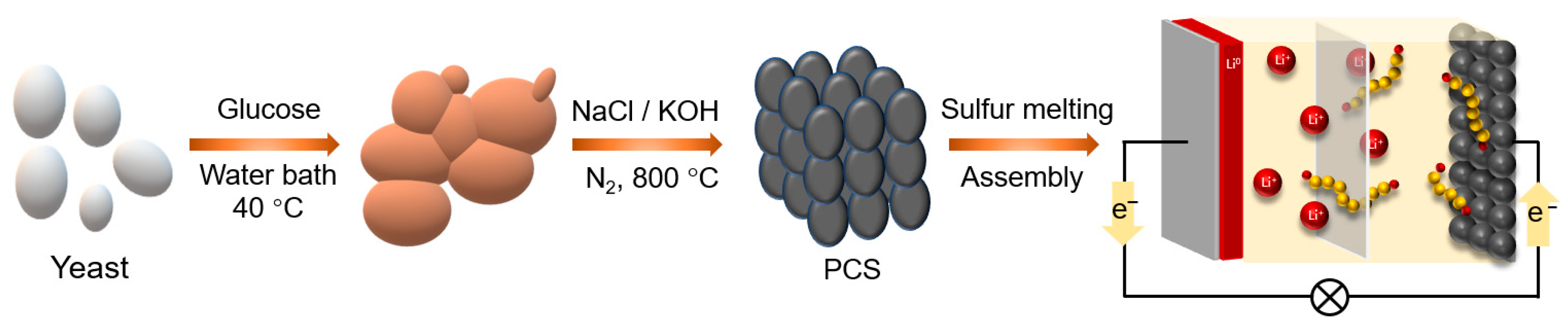
2.1. Preparation of Porous Carbon Materials

First, 2 g of edible yeast (instant dry yeast, 12 g, Angel, China) was used as carbon source, and 1 g of glucose and 50 mL of deionized water were mixed and stirred in a beaker to get a uniformly dispersed solution. The mixture was heated at 40 °C and kept for 40 min in a water bath. Then, the supernatant was removed by centrifugation, and the resulting product was mixed with 15 g of NaCl, added to 50 mL of deionized water, and heated at 80 °C with a magnetic stirrer until the solvent was completely evaporated. Afterward, the product was transferred into a Muffle furnace and heated to 800 °C under flowing nitrogen gas protection for 3 h. The reaction of yeast in the carbonization process could be simply expressed as C x H y O z 800   ,     N 2   C + C x 1 O z y 2 + y 2 H 2 O . The resultant material was washed with water to remove the residual NaCl and then dried in oven for 12 h. The yielded carbon product was then mixed with KOH at a mass ratio of 1:4 and carbonized at 800 °C under nitrogen gas for 1 h. The derived porous carbon structure (PCS) material was cleaned with 1 M HCl, rinsed with deionized water and ethanol three times, and denoted as PCS-800. Via the same procedure, PCS-700 and PCS-900 were activated at 700 and 900 °C, respectively.

2.2. Preparation of PCS/S Composites

The prepared PCS-800 and S were ground for 20 min with the mass ratio of 3:7. The resultant powder was added to 5 mL beaker, with 2 mL of CS2 as the solvent. The solution was heated and stirred at 70 °C until the CS2 solvent was completely volatilized. The resultant precipitate was ground again, transferred into a sealed stainless steel mold, and held in a Muffle furnace at 155 °C for 12 h. Afterward, the temperature was elevated to 200 °C for 1 h. The derived composite material was then taken out and marked as PCS-800/S for the application of Li–S battery cathode. The same process was adopted to prepare PCS-700/S and PCS-900/S cathodes for reference.

2.3. Assembly of Li–S Battery

The sulfur-infiltrated PCS, 5% graphene paste (with 0.5% PVDF in the solvent of N-Methyl pyrrolidone), and conducting additive super P were mixed and ground at the mass ratio of 8:1:1, with a certain amount of NMP as solvent to produce a uniform paste. The obtained slurry was coated onto a 20 μm thick aluminum foil and placed in an oven to dry at 60 °C for 12 h. Then, the foil was cut into round pieces with a diameter of 12 mm as the positive electrode. The loading of electrode material was estimated to be 1.8 mg cm−2, and the corresponding sulfur loading was 1.2 mg cm−2. With a Li metal anode, Celgard 2300 separator, and the electrolyte of 1 mol L−1 lithium bis(trifluoromethanesulfonyl)imide dissolved in a mixed solvent of 1,3-dioxolane and 1,2-dimethoxyethane (1:1 in volume), the Li–S battery was assembled. The electrolyte added to each coin cell was 30 μL, indicating an electrolyte-to-sulfur ratio of 22 μL mg−1. The assembled battery was rested for 24 h before electrochemical testing.

2.4. Characterization

By means of thermal field-emission scanning electron microscope (SEM, Gemini 500, Zeiss, Germany) and field-emission transmission electron microscope (TEM, JEM-2100F, JEOL, Japan), the morphology and microstructure were analyzed. Raman spectrometer (Labram HR Evolution, HORIBA Jobin, France) and X-ray diffractometer (X-Pert Pro MPD, Nalytical, The Netherlands) were used to characterize the graphitization state of the carbon structures. Energy dispersion spectrum (EDS) was used for the elemental mapping analysis. A thermogravimetric analyzer (TGA, STA449F5, Netzsch, Germany) was used to determine the content of sulfur in sulfur/carbon composites. Nitrogen gas absorption–desorption isotherm was obtained by gas adsorption instrument (Autosorb-IQ3, Quantachrome Instruments, USA) to estimate the specific surface area, pore volume, and pore size distribution. The surface element bonding state was determined by X-ray photoelectron spectrometer (Escalab 250XI, Thermo Scientific, USA). The electrochemical properties of the Li–S battery were tested using the CHI760E and DH7000 workstations.

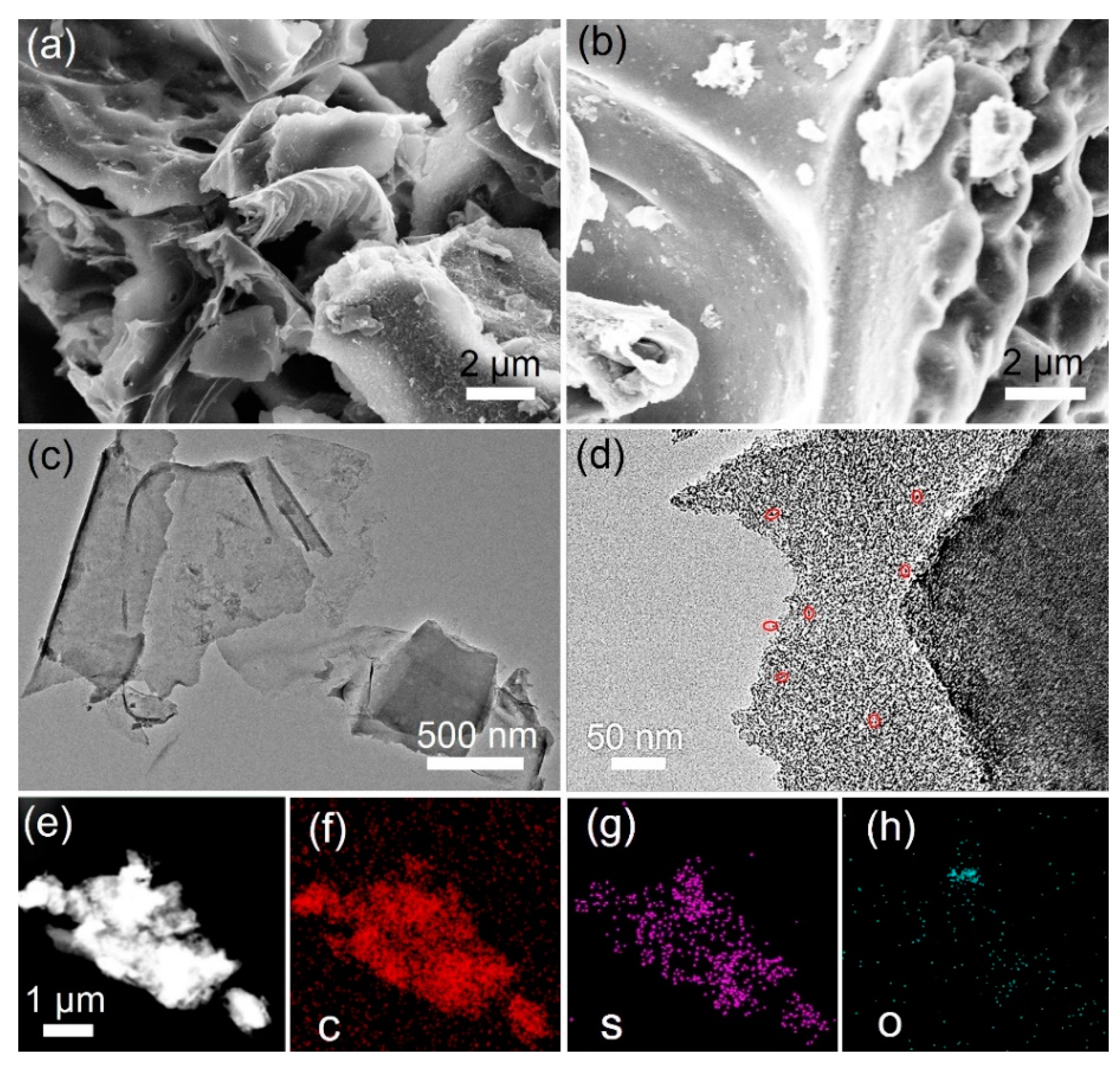
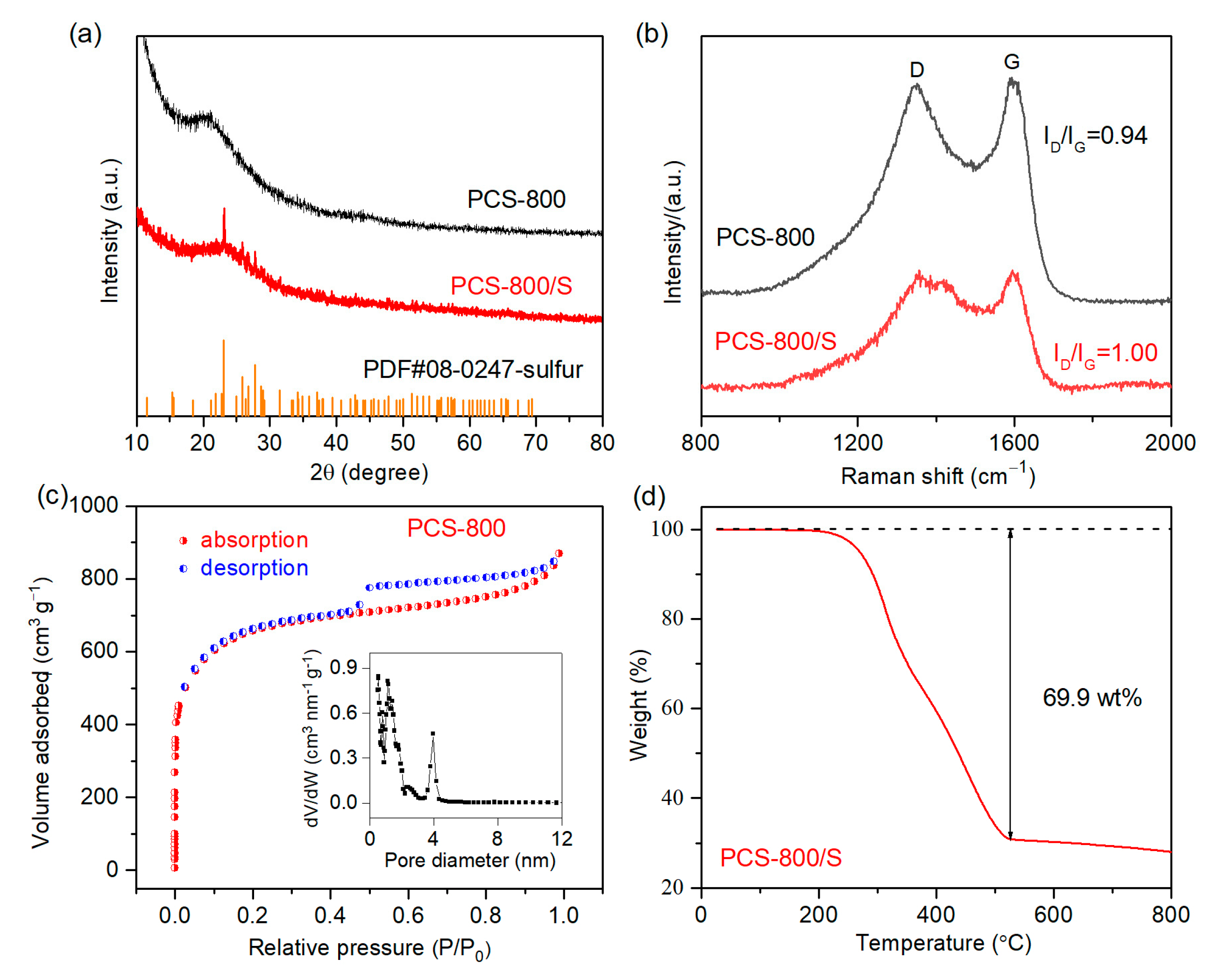
3. Results and Discussion

The fabrication process of a porous carbon-sheet-based Li–S battery is shown in Figure 1. Yeast is chosen as the carbon precursor due to the intrinsic biological structure that presents as a unicellular fungal organism. The main chemical components of this yeast are carbohydrates, proteins, and lipids that are easy to be carbonized with a regular cellular structure [32]. The glucose added to the water bath at 40 °C provides the nutrient source for the yeast to propagate and grow. The cultured yeast is then mixed with NaCl in a sealed tubular furnace and carbonized at 800 °C. During this process, the yeast-derived carbon grows on the surface of NaCl crystals and became porous after the NaCl is washed. It should be noted that except for micro- and mesopores, NaCl is a crystallized template that produces large pores in the resultant carbon structures [33,34], while KOH is generally employed to produce abundant micropores during the activation of carbon structure, as it is uniformly dispersed [35,36]. As a result, the yeast-derived PCS structure can be obtained. Afterward, sulfur is fused into the porous carbon structure at 155 °C, accompanied by an elevated temperature treatment at 200 °C to drive the infused sulfur into the distant microporous spaces and promote the uniform distribution of sulfur in the carbon structures. The resultant sulfur/carbon composite cathode is further assembled into a Li–S battery for electrochemical evaluation.
The morphology of the yeast-derived carbon materials obtained at 800 °C was observed by SEM. As shown in Figure 2a, the surface of PCS-800 demonstrated a relatively continuous and complete sheet structure with observable pore sizes of above 1 μm, which can be attributed to the intrinsic structure of yeast after activation and the template effect of NaCl that maintained the integrity of the raw material through the process of high-temperature carbonization. The observed multi-layered sheet structure of the carbon material can mitigate the negative effect of volume expansion/contraction and help to restrict the shuttling of polysulfides. It is obvious that the distribution of pores and other kinds of defects can enhance the specific surface area, increase the number of activated sites, and, hence, improve the sulfur storage capacity and utilization rate [37]. Meanwhile, the porous space in the carbon structure also provides transfer channels for the rapid transport of the electrolyte and reactive charges and enhances the reaction efficiency of the resultant batteries [38]. Therefore, the porous structure, especially the micropores, is essential in the cathode materials. With regards to the current study, KOH plays an important role in the process of pore generation, and the following reactions occur during the high-temperature treatment.
6 K O H + 2 C 2 K + K 2 C O 3 + 3 H 2
K 2 C O 3 K 2 O + 3 C O
C + K 2 O 2 K + C O
On the one hand, the gases release through the reactions above penetrate the carbon skeleton and reshape the original pore structure [39]. On the other hand, the processing temperature of 800 °C exceeds the boiling point of metal K, 762 °C. The releasing of vapor-phase potassium continues to expand and open up new channels in the carbon structure.
Figure 2b shows that after sulfur melting, the surface of PCS-800/S becomes smoother and thicker, due to most of the open spaces in PCS being occupied by sulfur. The white edges in this image can be attributed to the low conductivity of sulfur and the aggregated electrons on the surface of the sample. Figure S1 shows the morphology of yeast-derived carbon that was treated at 700 °C. Compared with the material carbonized at 800 °C, there are fewer observed defects and pores, corresponding to a decrease in sulfur storage capacity and the transport of the electrolyte. On the contrary, the material carbonized at 900 °C shows obvious fragmentation (Figure S2). Therefore, by comparing the different carbonization temperatures, the yeast carbonized at 800 °C is adopted for the sulfur host in the cathodes of Li–S batteries.
TEM was further employed to assess the structural changes in the activated carbon material and the distribution of elements before and after sulfur melting. As shown in Figure 2c, the material carbonized at 800 °C appeared in the form of a nanosheet. The radial dimensions of such sheets are 800~1800 nm, with an almost electron-transparent thickness. This is beneficial for the storing of sulfur and the efficient charge transfer during the electrochemical process [40]. Moreover, a thin and flexible carbon nanosheet can accommodate the volume change in sulfur to maintain the structural integrity of the cathode. Figure S3 shows the image of PCS-800/S, which shows that there are still different pores of 20~100 nm in the composite after sulfur melting. Thus, these vacancies can provide adsorption sites for the polysulfide and leave extra buffer room for the volume expansion of sulfur. In addition, there is no observation of aggregated sulfur particles in the image, which indicates that the sulfur has been uniformly fused into the carbon structure. The high-resolution TEM image shown in Figure 2d reveals that the sulfur particles are distributed evenly on the carbon nanosheet, with the typical particle dimensions estimated by ImageJ software of of 2~8 nm. The EDS result in Figure 2e–h shows the spatial distribution of elements in the carbon structure. The C, S, and O are spread uniformly in the PCS-800/S cathode’s materials, and their atomic percentages are 96.51%, 1.35%, and 2.14%, respectively. This indicates that the sulfur melted into the inside pores of PCS-800, because most of the sulfur left on the surface volatizes under the focused electron beam irradiation when taking photos in the TEM chamber. It should be noted that the presence of the O element provides plenty of active sites for sulfur fixation and conversion, which is conducive to the electrochemical performance of the resultant Li–S batteries.
Figure 3a shows that PCS-800 has a bulging peak at around 24°, but no other miscellaneous peaks can be seen in the curve, indicating that the porous carbon sheet structure is mainly amorphous. After melting the sulfur, the intensity of the bulging peak attenuates a little, but the sulfur peaks become more protruding. However, when compared with the standard PDF card of elemental sulfur (Figure 3a), the intensity of the sulfur peaks is significantly reduced. This can be ascribed to the sulfur being infused into the pores of the carbon material, as the signal of sulfur is difficult to detect. Nevertheless, this also reveals the excellent sulfur fixation ability of the PCS’s materials. As further estimated by the peaks of the XRD pattern, the size of the sulfur in PCS-800/S is in the range of 3~5 nm. The amorphous structures of PCS synthesized at the control temperatures of 700 and 900 °C can also be found in Figure S4.
Figure 3b shows the Raman spectra of PCS-800 and PCS-800/S, and the two obvious peaks located at 1350 and 1580 cm−1 are attributed to the D and G peaks, respectively. Among them, the D peak represents the vibration of disordered, defective, and marginal carbon, while the G peak reflects the s p 2 hybrid carbon in the graphitic structure. Thus, the ratio of the peak intensity of I D / I G reveals the graphitization degree of the carbon materials. The lower the ratio is, the higher the graphitization degree is. The I D / I G ratio of PCS-800 is 0.93, while the I D / I G value of PCS-800/S after sulfur melting is 1.00, which has increased a bit compared with the sample before sulfur melting. This indicates that the graphitization degree of the PCS is reduced after the treatment of sulfur infusion [41,42]. This is also supported by the results demonstrated in Figure S5. As the carbonization temperature increases from 700 °C to 800 to 900 °C, the I D / I G ratios decrease from 0.96 to 0.94 to 0.71, respectively. This can be ascribed to the increased temperature-induced structural damage in the carbon materials, while after sulfur infusion, the corresponding ratios further increase to 0.99, 1.00, and 0.96, respectively (Figure S6). It is also interesting to notice that there is a shoulder peak to the D band at ~1420 cm−1, after sulfur melting. However, this is popular in the high-temperature-annealed porous carbon/sulfur composite for a Li–S battery cathode [43], and it is obviously introduced through the sulfur melting process. Based on previous studies, this shoulder peak could be ascribed to the fractured S8 ring that reacts with the oxygen or carbon species in PCS-800 and to the sulfur-containing radicals or ions formed in the composite [44].
As for the host of the cathode material, a sufficient sulfur storage capacity and abundant ion conducting channels are required, and, thus, the specific surface area is an important indicator and evaluation criterion [45]. Here, we use a physical adsorption instrument to analyze the structure of the porous carbon host synthesized at 800 °C. Figure 3c shows the nitrogen adsorption and desorption isothermal curve of PCS-800. The BET equation is employed to calculate the specific surface area, which is estimated to be 2410 m2 g−1. The inset shows the detailed pore size distribution diagram of PCS-800. It is obvious that the pore size is mainly in the microporous region of 0~2 nm and the mesoporous region of 2~5 nm [46]. The abundant porous structure and high surface area of PCS-800 can be attributed to the sufficient amount of the NaCl template and sufficient activation time at 800 °C [47,48]. On the one hand, carbon materials with multi-pore size distribution and a high specific surface area are conducive to be used as the sulfur host in Li–S batteries, owing to the excellent accommodation capability of active substances. On the other hand, the co-existence of microporous and mesoporous structures can provide effective transport channels for both ions and electrons during the electrochemical process [49].
Figure 3d shows the TG curve of PCS-800/S tested under nitrogen gas protection. TGA is usually used to analyze the sulfur content in a Li–S battery cathode to estimate the specific discharge capacity. The mass changes with temperature mainly occur between 200 and 520 °C, wherein the mass decreases rapidly between the temperatures of 200 and 350 °C. This is mainly due to the evaporation of sulfur between the surface of the carbon material and the carbon particles, accounting for a mass loss of about 35% in this stage [50]. In the second phase, between 350 and 520 °C, the mass loss slows down, which can be attributed to the removal of short-chain sulfur molecules in the porous structure. After 520 °C, the mass does not obviously change, and the remaining elements in the composite are C and O, indicating that the total mass loss of PCS-800/S is about 69.9 wt% [51,52].
XPS is a widely used technique to analyze the elemental composition and chemical state of different materials. In this study, XPS is also employed to investigate the surface properties of the composite cathode PS-800/S, and the result is demonstrated in Figure 4. The spectra in Figure 4a reveals that the cathode material mainly contains three kinds of elements, i.e., C, S, and O. The atomic proportions of C (76.04%), S (7.96%), and O (16%) are given along with the XPS result. The relative elemental contents are quickly read from the shallow surface layer (usually less than 5 nm) of PCS-800/S, according to the shooting manner of the XPS analyzer. Thus, the relative S and O contents are apparently higher than the outcomes revealed by EDS mapping. The peaks at 533.1 and 286.1 eV in Figure 4a are attributed to the core-level electrons of O 1s and C 1s, respectively [53], while the S signals exhibit two valence states of S 2s and S 2p, with corresponding peaks at 165.1 and 228.0 eV, respectively. The high-resolution spectrum of the S 2p curve is demonstrated in Figure 4b, which is analyzed using the software for XPS peak segmentation and fitted. The main states of S 2p3/2 and S 2p1/2 are observed at 164.1 and 165.3 eV, respectively [54]. However, a weak peak at 169 eV is also detected, which can be attributed to the XPS signal of the sulfate that formed due to the oxidation of sulfur during the fabrication of PCS-800/S. In the high-resolution spectrum of C 1s (Figure 4c), the peaks at 284.7 and 285.6 eV are assigned to the bonds of C–C/C=C and C–S, respectively [55,56]. The formation of C–C/C=C bonds can be attributed to the s p 2 hybridization of the carbon structure under 800 °C treatment. The C–S bond forms during the fabrication of the sulfur/carbon composite, which helps to restrict the diffusion of polysulfides via chemisorption. Additionally, a weak peak at 289.8 eV was observed, which mainly corresponds to the O–C=O bond [57]. The analysis of the XPS spectra provides important information about the chemical composition and valence state of the sulfur/carbon composite material, which is crucial for understanding its properties and contributions to the battery cathode. Figure 4d shows the deconvolution of O 1s of the PCS-800/S cathode, in which the separated peaks at 533.0 and 532.1 eV are assigned to the XPS signals of C=O and C–OH, respectively.
Figure 5a shows the result of the CV test for the cathode materials prepared at 700, 800, and 900 °C. There are two distinct reduction peaks when scanned from high to low voltage. At ~2.3 V, the elemental S8 ring starts to break and react with Li+ ions to produce the long-chain polysulfide of Li 2 Sn   ( 4 N 8 ) and then further converts to the short-chain polysulfide of Li 2 S x   ( 1 x < 4 ) . The reduction peak at the lower voltage of 2.0 V mainly corresponds to the conversion of the short-chain polysulfide to L i 2 S 2 / L i 2 S . The polysulfide shuttling that affects the performance of Li–S batteries mainly occurs during the discharge process, leading to the loss of active materials. In the positive scanning from low to high voltage, there is an oxidation peak between 2.4 and 2.5 V, which mainly corresponds to the transformation of short-chain sulfides to long-chain sulfides [58]. By comparing the CV curves of the three cathodes, it can be found that the second reduction peak potential of PCS-800/S is higher than that of the other two cathodes. A larger discharge potential indicates a higher chemical reaction activity, which is conducive to the transformation of sulfur intermediates. Figure 5b shows the first cycle charge–discharge curves of the cathodes. PCS-800/S not only has a higher discharge specific capacity of 1502 mAh g−1 but also has a smaller polarization degree than PCS-700/S and PCS-900/S. The high initial discharge capacity may be attributed to the good infusion and uniform distribution of sulfur inside the porous carbon structures. This indicates that the structure of PCS-800/S is beneficial to the conversion of long-chain polysulfides to short-chain polysulfides and is more suitable for the cathodes of Li–S batteries. However, it is worth noting that there is a small discharge plateau at ~1.8 V for the PCS-800/S cathode. This can be attributed to the confined sulfur particles in the distant micropores of the porous carbon structure of PCS-800, resulting in a delayed release of capacity, which is usually reflected by the small plateau in the discharge profile [59].
It can be clearly seen from the cycling diagram in Figure 5c that the specific capacity of PCS-800/S is higher than that of PCS-700/S and PCS-900/S over 100 cycles, and the initial discharge capacity of PCS-800/S is 1248 mAh g−1 after the third cycle. The higher discharge capacity indicates the higher utilization rate of the active substance, which benefits from the large specific surface area, sufficient pore volume, and structural integrity of the carbon host. However, there is no doubt that the capacity of PCS-800/S gradually decreases as the cycling proceeds. The main reason could be attributed to the shuttle effect, because the yeast-derived PCS-800 carbon host mainly provides physical restriction to the transfer of polysulfides. Thus, some of the sulfur are left on the anode side and in the electrolyte without shuttling back to the cathode during charging and discharging. This gradual loss of sulfur results in a capacity decrease as the cycling proceeds. In addition, due to the remarkably high surface area and structural integrity, sulfur is assumed to be well-diffused into PCS-800 and distributes more uniform on its carbon nanosheets than those of PCS-700 and PCS-900. As a result, the high utilization rate of sulfur in PCS-800/S is reflected by the high initial discharge capacity. However, after 100 cycles, the capacity of PCS-800/S remains at 666.6 mAh g−1. Though it is higher than the 582.9 and 565.1 mAh g−1 for the PCS-700/S and PCS-900/S cathodes, respectively, the capacity retention rate of PCS-800/S is relatively low. The high utilization of sulfur and limited sulfur absorption mode may account for the continuous loss of the active material and a relatively faster capacity fading. A high capacity can also be noticed for PCS-800/S in the initial cycles even after the discharge current increases to 0.5 and 1 C, which further confirms the effective utilization of sulfur in the PCS-800/S cathode (Figure 5d). To demonstrate the practical absorption of PCS-800 to polysulfide, a 0.05 M Li2S6 solution is prepared in 1,2-dimethoxyethane (DME) and 1,3-dioxolane (DOL) (VDOL:VDME = 1:1), and 50 mg of PCS-800 is put into the solution. Figure S7 shows that the polysulfide solution changes from dark brown to light yellow after 12 h, indicating that most of the Li2S6 are captured by PCS-800. This is convincible proof that PCS-800 has an excellent absorption capability for the polysulfides in Li–S batteries.
Figure 5e shows the AC impedance profiles of the cathodes before the electrochemical reaction. Each of the curves consist of an obvious semicircle in the high-frequency region and an inclined line in the low-frequency region. The diameter of the semicircle in the high-frequency region reflects the charge transfer impedance ( R c t ) of the battery. The slope of the line region in the low-frequency segment reflects the ion diffusion rate [60]. The factors that affect the R c t value in the battery mainly include the ionic conductivity of the electrode material, the charge transfer rate of the electrolyte, and the interfacial resistance between them [61,62]. It can be seen from Figure 5e that the diameter of the semicircle of the PCS-800/S cathode is apparently smaller than that of the other two cathodes, indicating the smooth charge transference of PCS-800/S-based batteries. The EIS curves are further fitted by Z-view software, and the corresponding R c t values of cathodes PCS-700/S, PCS-800/S, and PCS-900/S before cycling are 31.4, 15.2, and 48.6 Ω, respectively. This indicates that the structural integrity and relatively high conductivity of the PCS-800/S electrode are conducive to improve the electrochemical reaction kinetics during the charging/discharging process. It also helps to promote the effective contact of the sulfur and electrolyte in the battery and, thus, to enhance the sulfur utilization rate. Figure 5f shows the impedance map of the electrodes after 100 cycles. The spectra evolve into three segments: high-frequency, low-frequency, and intermediate-frequency regions. The resistance ( R s ) of the ions penetrating through the surface insulation layer of the active substance is reflected by the high-frequency semicircle, while the intermediate-frequency semicircle region reveals the R c t of the charge transfer through the solid liquid interface. It is obvious that the R s (7.3 Ω) and R c t (7.9 Ω) of the PCS-800/S cathode obtained by Z-view fitting are smaller than those of the other two cathodes, and the slope of the line in the low-frequency region is higher than them, indicating that PCS-800/S exhibits excellent reaction activity after 100 cycles. Therefore, the yeast-derived cathode demonstrates a high electrochemical performance in the application of Li–S batteries.

4. Conclusions

Yeast propagated in glucose culture is used as the carbon source to prepare porous carbon structures with the assistance of a NaCl crystal template and KOH activator. By means of physical characterization and electrochemical testing, the resultant PCS material that was synthesized at 800 °C possesses a high surface area of 2410 m2 g−1. The unique pore structure is favorable for sulfur storage and helps to restrict the shuttling of polysulfides and attenuate the shuttle effect. At a current density of 0.2 C, the initial discharge capacity of PCS-800/S is as high as 1502 mAh g−1, and the Coulombic efficiency after 100 cycles is ~98.6%. As a carbon precursor material, the yeast-based biomass has a wide range of sources, a low cost, environmental friendliness, and sustainable productivity, contributing to one of the most promising cathode materials for high-performance Li–S batteries.

Supplementary Materials

The following supporting information can be downloaded at: https://www.mdpi.com/article/10.3390/batteries9060289/s1, Figure S1: SEM image of PCS-700. There are few observable defects and pores compared with PCS-800; Figure S2: SEM image of PCS-900. The carbon material shows obvious fragmentation; Figure S3: TEM image of PCS-800/S. There are different pores of 20~100 nm in the cathode material and no observable aggregated sulfur particles; Figure S4: XRD patterns of PCS-700, PCS-700/S, PCS-900, and PCS-900/S. After sulfur melting, the sulfur peaks are protruding; Figure S5: Raman spectra of PCS-700, PCS-800, and PCS-900. As the carbonization temperature increases, the ID⁄IG ratios decreases accordingly; Figure S6: Raman spectra of PCS-700/S, PCS-800/S, and PCS-900/S. After sulfur melting, the ID⁄IG ratio increases and a small shoulder peak to D band at ~1400 cm−1 appeared; Figure S7: Optical image the absorption of PCS-800 to Li2S6 in DOL/DME solution. The polysulfide solution changes from dark brown to light yellow after 12 h.

Author Contributions

Conceptualization, Z.H. and L.Z.; methodology, Z.H. and X.D.; validation, W.L. and L.L.; formal analysis, X.D.; investigation, Z.H. and W.L.; writing—original draft preparation, Z.H. and X.D.; writing—review and editing, F.M.; supervision, J.L.; project administration, J.L.; funding acquisition, F.M.; Z.H. and X.D. equally contributed to this work. All authors have read and agreed to the published version of the manuscript.

Funding

This research was funded by the National Natural Science Foundation of China (Grant No. 52102040), the Fundamental Research Funds for the Central Universities (Grant No. JZ2022HGTB0280), and the National College Students Innovation and Entrepreneurship Training Program (Grant No. S202110359038).

Data Availability Statement

The data that support the findings of this study are available from the corresponding author upon reasonable request.

Conflicts of Interest

The authors declare no conflict of interest.

References

  1. Feng, S.; Fu, Z.-H.; Chen, X.; Zhang, Q. A review on theoretical models for lithium–sulfur battery cathodes. InfoMat 2022, 4, e12304. [Google Scholar] [CrossRef]
  2. Park, J.W.; Jo, S.C.; Kim, M.J.; Choi, I.H.; Kim, B.G.; Lee, Y.J.; Choi, H.Y.; Kang, S.; Kim, T.; Baeg, K.J. Flexible high-energy-density lithium-sulfur batteries using nanocarbon-embedded fibrous sulfur cathodes and membrane separators. NPG Asia Mater. 2021, 13, 30. [Google Scholar] [CrossRef]
  3. Hong, H.; Che Mohamad, N.A.R.; Chae, K.; Marques Mota, F.; Kim, D.H. The lithium metal anode in Li–S batteries: Challenges and recent progress. J. Mater. Chem. A 2021, 9, 10012–10038. [Google Scholar] [CrossRef]
  4. Lim, W.-G.; Kim, S.; Jo, C.; Lee, J. A Comprehensive Review of Materials with Catalytic Effects in Li–S Batteries: Enhanced Redox Kinetics. Angew. Chem. Int. Ed. 2019, 58, 18746–18757. [Google Scholar] [CrossRef] [PubMed]
  5. Fan, X.; Sun, W.; Meng, F.; Xing, A.; Liu, J. Advanced chemical strategies for lithium–sulfur batteries: A review. Green Energy Environ. 2018, 3, 2–19. [Google Scholar] [CrossRef]
  6. Zhou, G.M.; Chen, H.; Cui, Y. Formulating energy density for designing practical lithium-sulfur batteries. Nat. Energy 2022, 7, 312–319. [Google Scholar] [CrossRef]
  7. Ye, Z.; Jiang, Y.; Li, L.; Wu, F.; Chen, R. A High-Efficiency CoSe Electrocatalyst with Hierarchical Porous Polyhedron Nanoarchitecture for Accelerating Polysulfides Conversion in Li-S Batteries. Adv. Mater. 2020, 32, 2002168. [Google Scholar] [CrossRef]
  8. Xu, B.; Zhao, Y.; Liu, H.; Cheng, S.; Liu, J.; Meng, F. Nanolayer GO coated CNT film interlayer for lithium-sulfur batteries with enhanced cycling stability. Mater. Lett. 2021, 305, 130753. [Google Scholar] [CrossRef]
  9. Qi, C.; Zu, S.; Zhu, X.; Zhang, T.; Li, L.; Song, L.; Jin, Y.; Zhang, M. Bamboo-shaped Co@NCNTs as superior sulfur host for Li-S batteries. Appl. Surf. Sci. 2022, 601, 154245. [Google Scholar] [CrossRef]
  10. Jiang, J.C.; Fan, Q.N.; Chou, S.L.; Guo, Z.P.; Konstantinov, K.; Liu, H.K.; Wang, J.Z. Li2S-Based Li-Ion Sulfur Batteries: Progress and Prospects. Small 2021, 17, 1903934. [Google Scholar] [CrossRef]
  11. He, J.R.; Bhargav, A.; Manthiram, A. High-Performance Anode-Free Li-S Batteries with an Integrated Li2S-Electrocatalyst Cathode. ACS Energy Lett. 2022, 7, 583–590. [Google Scholar] [CrossRef]
  12. Li, Q.; Liu, Y.; Wang, Y.; Chen, Y.; Guo, X.; Wu, Z.; Zhong, B. Review of the application of biomass-derived porous carbon in lithium-sulfur batteries. Ionics 2020, 26, 4765–4781. [Google Scholar] [CrossRef]
  13. Wang, J.; He, Y.S.; Yang, J. Sulfur-based composite cathode materials for high-energy rechargeable lithium batteries. Adv. Mater. 2015, 27, 569–575. [Google Scholar] [CrossRef] [PubMed]
  14. Puthirath, A.B.; Baburaj, A.; Kato, K.; Salpekar, D.; Chakingal, N.; Cao, Y.; Babu, G.; Ajayan, P.M. High sulfur content multifunctional conducting polymer composite electrodes for stable Li-S battery. Electrochim. Acta 2019, 306, 489–497. [Google Scholar] [CrossRef]
  15. Jiang, M.; Gan, B.; Deng, Y.; Xiong, Y.; Tan, R. Suppressing Self-Discharge with Polymeric Sulfur in Li-S Batteries. Materials 2018, 12, 64. [Google Scholar] [CrossRef]
  16. Li, H.; Shao, F.; Wen, X.; Ding, Y.; Zhou, C.; Zhang, Y.; Wei, H.; Hu, N. Graphene/MXene fibers-enveloped sulfur cathodes for high-performance Li-S batteries. Electrochim. Acta 2021, 371, 137838. [Google Scholar] [CrossRef]
  17. Cheng, M.; Zhao, H.; Zhao, Z.; Wang, J.; Cao, L.; Zhang, H.; Duan, X.; Wang, C.; Wang, J.; Wang, J.; et al. The improvement of pitch activation by graphene for long-cycle Li–S batteries. Green Chem. 2018, 20, 4675–4683. [Google Scholar] [CrossRef]
  18. Gueon, D.; Yoon, J.; Hwang, J.T.; Moon, J.H. Microdomain sulfur-impregnated CeO2-coated CNT particles for high-performance Li-S batteries. Chem. Eng. J. 2020, 390, 124548. [Google Scholar] [CrossRef]
  19. Wang, B.; Guo, W.; Fu, Y. Anodized Aluminum Oxide Separators with Aligned Channels for High-Performance Li-S Batteries. ACS Appl. Mater. Interfaces 2020, 12, 5831–5837. [Google Scholar] [CrossRef]
  20. Yanilmaz, M. TiO2-decorated porous carbon nanofiber interlayer for Li-S batteries. RSC Adv. 2020, 10, 16570–16575. [Google Scholar] [CrossRef]
  21. Meng, F.; Xu, B.; Long, T.; Cheng, S.; Li, Y.; Zhang, Y.; Liu, J. ZnS nanolayer coated hollow carbon spheres with enhanced rate and cycling performance for Li-S batteries. Sci. China Technol. Sci. 2021, 65, 272–281. [Google Scholar] [CrossRef]
  22. Xu, C.Y.; Du, R.; Yu, C.B.; Shi, Z.Y.; Wang, J.L.; Li, T.R. Glucose-Derived Micro–Mesoporous Carbon Spheres for High-Performance Lithium–Sulfur Batteries. Energy Fuel 2022, 37, 1318–1326. [Google Scholar] [CrossRef]
  23. He, J.; Gao, Z.; Li, X. Yeast-Derived Carbon Nanotube-Coated Separator for High Performance Lithium-Sulfur Batteries. JOM 2021, 73, 2516–2524. [Google Scholar] [CrossRef]
  24. Vijaya Kumar Saroja, A.P.; Arjunan, A.; Muthusamy, K.; Balasubramanian, V.; Sundara, R. Chemically bonded amorphous red phosphorous with disordered carbon nanosheet as high voltage cathode for rechargeable aluminium ion battery. J. Alloy Compd. 2020, 830, 154693. [Google Scholar] [CrossRef]
  25. Arjunan, A.; Subbiah, M.; Sekar, M.; Vs, A.P.; Balasubramanian, V.; Sundara, R. Biomass derived hierarchically porous carbon inherent structure as an effective metal free cathode for Li-O2/air battery. Electrochem. Sci. Adv. 2021, 1, e202000037. [Google Scholar] [CrossRef]
  26. Guo, X.T.; Wang, S.B.; Yang, B.; Xu, Y.X.; Liu, Y.; Pang, H. Porous pyrrhotite Fe7S8 nanowire/SiOx/nitrogen-doped carbon matrix for high-performance Li-ion-battery anodes. J. Colloid Interf. Sci. 2020, 561, 801–807. [Google Scholar] [CrossRef]
  27. Razzaq, A.A.; Yao, Y.Z.; Shah, R.; Qi, P.W.; Miao, L.X.; Chen, M.Z.; Zhao, X.H.; Peng, Y.; Deng, Z. High-performance lithium sulfur batteries enabled by a synergy between sulfur and carbon nanotubes. Energy Storage Mater. 2019, 16, 194–202. [Google Scholar] [CrossRef]
  28. Zhu, Q.C.; Deng, H.H.; Su, Q.M.; Du, G.H.; Yu, Y.; Ma, S.F.; Xu, B.S. A free-standing nitrogen-doped porous carbon foam electrode derived from melaleuca bark for lithium-sulfur batteries. Electrochim. Acta 2019, 293, 19–24. [Google Scholar] [CrossRef]
  29. Nurhilal, O.; Hidayat, S.; Sumiarsa, D.; Risdiana, R. Natural Biomass-Derived Porous Carbon from Water Hyacinth Used as Composite Cathode for Lithium Sulfur Batteries. Sustainability 2023, 15, 1039. [Google Scholar] [CrossRef]
  30. Liu, P.; Wang, Y.; Liu, J. Biomass-derived porous carbon materials for advanced lithium sulfur batteries. J. Energy Chem. 2019, 34, 171–185. [Google Scholar] [CrossRef]
  31. Imtiaz, S.; Zhang, J.; Zafar, Z.A.; Ji, S.; Huang, T.; Anderson, J.A.; Zhang, Z.; Huang, Y. Biomass-derived nanostructured porous carbons for lithium-sulfur batteries. Sci. China Mater. 2016, 59, 389–407. [Google Scholar] [CrossRef]
  32. Tian, Y.H.; Ren, Q.X.; Chen, X.Y.; Li, L.B.; Lan, X.Z. Yeast-Based Porous Carbon with Superior Electrochemical Properties. ACS Omega 2022, 7, 654–660. [Google Scholar] [CrossRef] [PubMed]
  33. Choi, J.H.; Park, S.K.; Kang, Y.C. A Salt-Templated Strategy toward Hollow Iron Selenides-Graphitic Carbon Composite Microspheres with Interconnected Multicavities as High-Performance Anode Materials for Sodium-Ion Batteries. Small 2019, 15, 1803043. [Google Scholar] [CrossRef] [PubMed]
  34. Li, C.H.; Liu, H.X.; Yu, Z.Y. Novel and multifunctional inorganic mixing salt-templated 2D ultrathin Fe/Co-N/S-carbon nanosheets as effectively bifunctional electrocatalysts for Zn-air batteries. Appl. Catal. B Environ. 2019, 241, 95–103. [Google Scholar] [CrossRef]
  35. Tan, Y.T.; Ren, J.N.; Li, X.M.; He, L.J.; Chen, C.M.; Li, H.B. Highly graphitic porous carbon prepared via K2FeO4-assisted KOH activation for supercapacitors. New J. Chem. 2022, 46, 14338–14345. [Google Scholar] [CrossRef]
  36. Wang, J.; Chen, S.; Xu, J.Y.; Liu, L.C.; Zhou, J.C.; Cai, J.J. High-surface-area porous carbons produced by the mild KOH activation of a chitosan hydrochar and their CO2 capture. New Carbon Mater. 2021, 36, 1081–1093. [Google Scholar] [CrossRef]
  37. Wang, D.; Liu, H.; Shan, Z.; Xia, D.; Na, R.; Liu, H.; Wang, B.; Tian, J. Nitrogen, sulfur Co-doped porous graphene boosting Li4Ti5O12 anode performance for high-rate and long-life lithium ion batteries. Energy Storage Mater. 2020, 27, 387–395. [Google Scholar] [CrossRef]
  38. Li, H.; Zhao, Z.R.; Li, Y.Y.; Xiang, M.W.; Guo, J.M.; Bai, H.L.; Liu, X.F.; Yang, X.Z.; Su, C.W. Waste-honeycomb-derived in situ N-doped Hierarchical porous carbon as sulfur host in lithium-sulfur battery. Dalton Trans. 2022, 51, 1502–1512. [Google Scholar] [CrossRef]
  39. Liu, H.; Liu, W.L.; Meng, F.C.; Jin, L.Y.; Li, S.L.; Cheng, S.; Jiang, S.D.; Zhou, R.L.; Liu, J.H. Natural nori-based porous carbon composite for sustainable lithium-sulfur batteries. Sci. China Technol. Sci. 2022, 65, 2380–2387. [Google Scholar] [CrossRef]
  40. Peng, H.-J.; Huang, J.-Q.; Zhang, Q. A review of flexible lithium–sulfur and analogous alkali metal–chalcogen rechargeable batteries. Chem. Soc. Rev. 2017, 46, 5237–5288. [Google Scholar] [CrossRef]
  41. Jiang, S.; Chen, M.; Wang, X.; Zhang, Y.; Huang, C.; Zhang, Y.; Wang, Y. Honeycomb-like nitrogen and sulfur dual-doped hierarchical porous biomass carbon bifunctional interlayer for advanced lithium-sulfur batteries. Chem. Eng. J. 2019, 355, 478–486. [Google Scholar] [CrossRef]
  42. Hou, J.; Tu, X.; Wu, X.; Shen, M.; Wang, X.; Wang, C.; Cao, C.; Pang, H.; Wang, G. Remarkable cycling durability of lithium-sulfur batteries with interconnected mesoporous hollow carbon nanospheres as high sulfur content host. Chem. Eng. J. 2020, 401, 126141. [Google Scholar] [CrossRef]
  43. Wu, D.; Chen, J.; Zhang, W.; Liu, W.; Li, J.; Cao, K.; Gao, Z.; Xu, F.; Jiang, K. Sealed pre-carbonization to regulate the porosity and heteroatom sites of biomass derived carbons for lithium-sulfur batteries. J. Colloid Interf. Sci. 2020, 579, 667–679. [Google Scholar] [CrossRef] [PubMed]
  44. Hannauer, J.; Scheers, J.; Fullenwarth, J.; Fraisse, B.; Stievano, L.; Johansson, P. The Quest for Polysulfides in Lithium–Sulfur Battery Electrolytes: An Operando Confocal Raman Spectroscopy Study. ChemPhysChem 2015, 16, 2755–2759. [Google Scholar] [CrossRef]
  45. Zhou, L.; Danilov, D.L.; Eichel, R.A.; Notten, P.H. Host materials anchoring polysulfides in Li–S batteries reviewed. Adv. Energy Mater. 2021, 11, 2001304. [Google Scholar] [CrossRef]
  46. Du, Y.; Huang, R.; Lin, X.; Khan, S.; Zheng, B.; Fu, R. Template-Free Preparation of Hierarchical Porous Carbon Nanosheets for Lithium-Sulfur Battery. Langmuir 2020, 36, 14507–14513. [Google Scholar] [CrossRef] [PubMed]
  47. Qiu, D.; Cao, T.; Zhang, J.; Zhang, S.-W.; Zheng, D.; Wu, H.; Lv, W.; Kang, F.; Yang, Q.-H. Precise carbon structure control by salt template for high performance sodium-ion storage. J. Energy Chem. 2019, 31, 101–106. [Google Scholar] [CrossRef]
  48. Ponomarev, N.; Sillanpää, M. Combined chemical-templated activation of hydrolytic lignin for producing porous carbon. Ind. Crop. Prod. 2019, 135, 30–38. [Google Scholar] [CrossRef]
  49. Liu, W.; Fan, X.; Xu, B.; Chen, P.; Tang, D.; Meng, F.; Zhou, R.; Liu, J. MnO-Inlaid hierarchically porous carbon hybrid for lithium-sulfur batteries. Nano Sel. 2020, 2, 573–580. [Google Scholar] [CrossRef]
  50. Shi, Z.; Feng, W.; Wang, X.; Li, M.; Song, C.; Chen, L. Catalytic cobalt phosphide Co2P/carbon nanotube nanocomposite as host material for high performance lithium-sulfur battery cathode. J. Alloys Compd. 2021, 851, 156289. [Google Scholar] [CrossRef]
  51. Yan, Y.; Shi, M.; Wei, Y.; Zhao, C.; Chen, L.; Fan, C.; Yang, R.; Xu, Y. The hierarchical porous structure of carbon aerogels as matrix in cathode materials for Li-S batteries. J. Nanoparticle Res. 2018, 20, 260. [Google Scholar] [CrossRef]
  52. Li, Z.; Li, X.; Liao, Y.; Li, X.; Li, W. Sulfur loaded in micropore-rich carbon aerogel as cathode of lithium-sulfur battery with improved cyclic stability. J. Power Sources 2016, 334, 23–30. [Google Scholar] [CrossRef]
  53. Liu, N.N.; Wu, X.; Zhang, Y.; Yin, Y.Y.; Sun, C.Z.; Mao, Y.C.; Fan, L.S.; Zhang, N.Q. Building High Rate Capability and Ultrastable Dendrite-Free Organic Anode for Rechargeable Aqueous Zinc Batteries. Adv. Sci. 2020, 7, 2000146. [Google Scholar] [CrossRef] [PubMed]
  54. Wang, Y.; Wang, Z.; Wu, D.; Niu, Q.; Lu, P.; Ma, T.; Su, Y.; Chen, L.; Li, H.; Wu, F. Stable Ni-rich layered oxide cathode for sulfide-based all-solid-state lithium battery. eScience 2022, 2, 537–545. [Google Scholar] [CrossRef]
  55. Greczynski, G.; Hultman, L. The same chemical state of carbon gives rise to two peaks in X-ray photoelectron spectroscopy. Sci. Rep. 2021, 11, 11195. [Google Scholar] [CrossRef]
  56. Wang, H.T.; Qiu, X.Y.; Wang, W.; Jiang, L.P.; Liu, H.F. Iron Sulfide Nanoparticles Embedded Into a Nitrogen and Sulfur Co-doped Carbon Sphere as a Highly Active Oxygen Reduction Electrocatalyst. Front. Chem. 2019, 7, 855. [Google Scholar] [CrossRef]
  57. Song, W.; Xu, C.; Li, M.; Cheng, Z.; Liu, Y.; Wang, P.; Liu, Z. Cobalt Nanocluster-Doped Carbon Micro-Spheres with Multilevel Porous Structure for High-Performance Lithium-Sulfur Batteries. Energies 2023, 16, 247. [Google Scholar] [CrossRef]
  58. Xu, Q.; Zhang, K.; Qian, J.; Guo, Y.; Song, X.; Pan, H.; Wang, D.; Li, X. Boosting Lithium–Sulfur Battery Performance by Integrating a Redox-Active Covalent Organic Framework in the Separator. ACS Appl. Energy Mater. 2019, 2, 5793–5798. [Google Scholar] [CrossRef]
  59. Long, T.; Meng, F.; Xu, B.; Zhao, Y.; Liu, W.; Wei, X.; Zheng, L.; Liu, J. Nitrogen-doped carbon nanotubes intertwined with porous carbon with enhanced cathode performance in lithium–sulfur batteries. Sustain. Energy Fuel 2020, 4, 3926–3933. [Google Scholar] [CrossRef]
  60. Wang, J.; Liang, J.; Wu, J.; Xuan, C.; Wu, Z.; Guo, X.; Lai, C.; Zhu, Y.; Wang, D. Coordination effect of network NiO nanosheet and a carbon layer on the cathode side in constructing a high-performance lithium–sulfur battery. J. Mater. Chem. A 2018, 6, 6503–6509. [Google Scholar] [CrossRef]
  61. Qiu, X.; Hua, Q.; Zheng, L.; Dai, Z. Study of the discharge/charge process of lithium–sulfur batteries by electrochemical impedance spectroscopy. RSC Adv. 2020, 10, 5283–5293. [Google Scholar] [CrossRef] [PubMed]
  62. Wang, T.; Zhu, J.; Wei, Z.; Yang, H.; Ma, Z.; Ma, R.; Zhou, J.; Yang, Y.; Peng, L.; Fei, H.; et al. Bacteria-Derived Biological Carbon Building Robust Li-S Batteries. Nano Lett. 2019, 19, 4384–4390. [Google Scholar] [CrossRef] [PubMed]
Figure 1. Schematic illustration showing the preparation of PCS for Li–S battery cathode.
Batteries 09 00289 g001
Figure 2. SEM images of (a) PCS-800 and (b) PCS-800/S. TEM images of (c) PCS-800 and (d) PCS-800/S with the sulfur particles shown in the red circle, and the spatial distribution of C, S, and O elements in PCS-800/S (eh).
Batteries 09 00289 g002
Figure 3. (a) XRD patterns of PCS-800 and PCS-800/S. (b) Raman spectra of PCS-800 and PCS-800/S. (c) Nitrogen gas adsorption–desorption isotherm of PCS-800 and the corresponding pore size distribution. (d) Thermogravimetric curve of PCS-800/S.
Batteries 09 00289 g003
Figure 4. The XPS spectrum (a) and high-resolution spectra of S 2p (b), C 1s (c), and O 1s (d) of PCS-800/S.
Batteries 09 00289 g004
Figure 5. The electrochemical properties of Li–S batteries with the cathode prepared at different temperatures. (a) CV curves, (b) GCD curves, (c) cycling stability, (d) rate performance, and EIS curves before (e) and after (f) cycling.
Batteries 09 00289 g005
Disclaimer/Publisher’s Note: The statements, opinions and data contained in all publications are solely those of the individual author(s) and contributor(s) and not of MDPI and/or the editor(s). MDPI and/or the editor(s) disclaim responsibility for any injury to people or property resulting from any ideas, methods, instructions or products referred to in the content.

