Article

Li3BO3-Li3PO4 Composites for Efficient Buffer Layer of Sulphide-Based All-Solid-State Batteries

1
Department of Advanced Materials Engineering, Graduate School Kyonggi University, 154-42, Gwanggyosan-ro, Yeongtong-gu, Suwon-si 16227, Gyeonggi-do, Republic of Korea
2
Hyundai Motor Company 150, Hyundaiyeonguso-ro, Namyang-eup, Hwaseong-si 18280, Gyeonggi-do, Republic of Korea
*
Author to whom correspondence should be addressed.
Batteries 2023, 9(6), 292; https://doi.org/10.3390/batteries9060292
Submission received: 20 March 2023 / Revised: 12 May 2023 / Accepted: 24 May 2023 / Published: 26 May 2023

Abstract

:
All-solid-state batteries (ASSBs) based on sulphide electrolytes are promising next-generation energy storage systems because they are expected to have improved safety, increased volumetric energy density, and a wide operating temperature range. However, side reactions at the cathode/electrolyte interface deteriorate the electrochemical performance and limit the commercialization of ASSBs. Surface coating of the cathode is an efficient approach for overcoming this issue. In this study, new Li3BO3 (LBO)-Li3PO4 (LPO) composites were applied as coating materials for high-Ni cathodes (NCM). PO4-based materials (such as LPO) have been used as coating layers because of their good chemical stability in sulphide electrolytes. However, the ionic conductivity of LPO is slightly insufficient compared to those of generally used ternary oxides. The addition of LBO could compensate for the low ionic conductivity of LPO and may provide better protection against sulphide electrolytes owing to the effect of LBO, which has been used as a good coating material. As expected, the LBO-LPO composites (LBPO) NCM exhibited superior discharge capacity, rate capability, and cyclic performance compared to the pristine and LPO-coated NCMs. X-ray photoelectron spectroscopy (XPS) and energy-dispersive X-ray spectroscopy (EDS) analyses confirmed that the LBPO coating on the cathodes successfully suppressed the byproduct formation and an undesirable interfacial layer, which are attributed to interfacial side reactions. This result clearly shows the potential of the LBPO coating as an excellent buffer layer to stabilise the oxide cathode/sulphide electrolyte interface.

1. Introduction

Today, lithium-ion batteries (LIBs) contribute to our lives in many ways [1,2,3,4,5,6,7,8]. LIBs are being used to make phone calls, work on a laptop computer, and drive an electric car. However, as LIBs are used in various fields, several risks are also highlighted. In particular, sudden fires caused by LIBs in electric vehicles and energy storage systems (ESS) have caused many casualties and property damage, and the need for awareness of this safety problem is becoming increasingly serious. The possibility of fire in LIBs originates from the flammable organic liquid electrolyte. Therefore, the most fundamental solution to this safety issue is to employ non-flammable inorganic solid electrolytes instead of liquid electrolytes [9,10,11,12,13,14,15]. Moreover, all-solid-state batteries (ASSBs) employing solid electrolytes are expected to be used at high or low temperatures, where LIBs are difficult to use, and have the potential to increase energy density [16,17,18,19].
Sulphide materials in the form of lithium thiophosphates are the most promising candidates for solid electrolytes for the commercial success of ASSBs. They have satisfactory ionic conductivities comparable to those of liquid electrolytes and can be contacted with electrodes through mechanical pressing without a high-temperature heating process [20,21,22]. However, recent studies have shown that sulphide electrolytes have a narrow electrochemical window, which means that they can decompose during ASSB operation [23,24,25,26]. Furthermore, severe interfacial reactions occur at the cathode/electrolyte interface because of the inherent chemical potential incompatibility between oxide cathodes and sulphide electrolytes [27,28,29,30], which drives high interfacial resistance at the interface. These points result in the electrochemical properties of sulphide-based ASSBs falling short of LIBs and becoming an obstacle limiting the commercialisation of ASSBS.
The usage of a stable coating layer between the oxide cathode and sulphide electrolyte is known to be an efficient solution to mitigate the interfacial reactions of ASSBs because it can act as a buffer to limit the interfacial reactions. To maintain the ion movement path between the solid electrolytes and cathodes, the buffer layer must also exhibit lithium-ion conductivity. Thus, ternary oxides containing Li ions, such as LiNbO3 [31,32,33], Li4TiO12 [25], Li2SiO3 [33], LiTaO3 [34,35], and Li2ZrO3 [36,37], have been generally applied as buffer layers for ASSBs. In addition, polyanionic oxides such as Li3PO4 (LPO) have also been reported as efficient buffer layers because of their good chemical stability in sulphide electrolytes [38,39]. However, research on utilising polyanionic oxides as a buffer layer has not yet been conducted compared to ternary oxides, despite the prediction of excellent effects beyond those of ternary oxides as a result of numerical computations [28,30,40].
In this study, we attempted to find new PO4-based compositions that can be successfully used as a buffer layer on the surface of cathodes to suppress unwanted interfacial reactions in ASSBs. Considering previous works, applying the LPO coating to the cathodes could considerably alleviate the side reactions at the cathode/sulphide electrolyte interface [38,39]. However, the ionic conductivity of LPO (~10−7–10−9 S·cm−1) [41] is somewhat lower than that of ternary oxides, such as LiNbO3 and LiTaO3 (~10−6 S·cm−1) [42]. Because the resistance to sulphides has already been verified [28,30,40], it is expected that PO4-based compositions will be used as a better buffer layer if the ionic conductivity can be further increased. To enhance the ionic conductivity of the PO4-based buffer layer, Li3BO3-Li3PO4 composites were used. The composition of Li3BO3 (LBO) has been reported to significantly increase the ionic conductivity of LPO [41]. It is also expected to create a synergic effect when combined with LPO because LBO has already been used as a good buffer layer of the cathode for ASSBs [43]. Moreover, boron can be obtained using inexpensive materials. In this study, Li3BO3-Li3PO4 (LBPO) composites were homogeneously coated on the surface of LiNi0.82Co0.12Mn0.06O2 (811 NCM cathode) and their properties were characterized using sulphide-based all-solid-state cells (ASSCs). To confirm the effect of the LBPO buffer layer, the cathode/electrolyte interface of ASSCs was analysed using X-ray photoelectron spectroscopy (XPS) and energy-dispersive X-ray spectroscopy (EDS).

2. Materials and Methods

A commercial high-Ni cathode composed of Li[Ni0.82Co0.12Mn0.06]O2 was supplied by Hyundai Mortor (NCM) and used as a pristine powder. Because it is a commercially available powder, several elements, including boron, were doped into the Li[Ni0.82Co0.12Mn0.06]O2 cathode. Originally, NCM powder was produced after forming a surface coating layer for LIBs; however, this process was omitted and supplied without a coating layer. Instead, LPO and LBPO layers were formed as coating layers for the ASSBs in this experiment. The LPO solution was prepared using polyphosphoric acid (H3PO4, 99.99%, Aldrich, St. Louis, MI, USA) and lithium ethoxide (CH3CHOLi, 99.9%, Aldrich) with mixing in a stoichiometric composition ratio. Boric acid (H3BO3, 99.999%, Aldrich) and lithium ethoxide were added to the LPO solution to prepare an LBO-LPO (LBPO) coating solution. The amount of LPO coating was adjusted to 0.1 and 0.15 wt.% based on the mass of the uncoated powder. The composition of LBPO was designed by fixing the amount of LPO and adding 0.05, 0.1, and 0.15 wt.% of LBO. After preparing a solution by dissolving the coating sources in reagent alcohol (99.9%, Aldrich) at 40 °C for 1 h, the pristine powder was mixed with the solution and stirred at 70 °C until the solution evaporated. A vacuum oven at 90 °C was used to completely dry the evaporated powder, which was then heat-treated in an oxygen atmosphere (O2 flow = 1000 cc∙min−1) at 400 °C for 1 h.
All-solid-state cells (ASSCs) containing pristine and coated NCMs were fabricated to determine the electrochemical performance of the cathodes. For the composite cathode, pristine or coated NCMs, sulphide solid electrolyte (Li6PS5Cl, supplied by Hyundai Mortor, Seoul, Republic of Korea), and carbon black (super C) were mixed in a weight ratio of 70:30:2. Pressurised cells were prepared using a composite cathode, sulphide solid electrolyte, and Li metal foil as the anode. A sulphide solid electrolyte (0.15 g) was placed in a 13-pie mould and compressed at a pressure of 12 MPa. Thereafter, 0.015 g of the composite cathode was placed on the opposite side and compressed at 44 MPa. Then, Al foil, which is a current collector, is placed on the composite cathode side, a Li-metal foil is placed on the opposite side, and a mould is assembled. Finally, pressurised cells were manufactured by applying a 3-axis pressure of 50 kgf∙cm−1 using a torque wrench to maintain the compressive strength. All the manufacturing processes were performed in a glove box filled with high-purity Ar gas. The discharge capacity was measured at constant current densities over a voltage range of 4.25–2.5 V (vs. Li).
The surface of the pristine and coated powders was observed using scanning electron microscopy (SEM, JSM-7610F PLUS), and the coating layer was confirmed through scanning transmission electron microscopy (STEM, JEOL JEM-2100F). To check for the presence of boron in the coating layer, the coated powders were analysed using XPS (Thermo Scientific K-Alpha plus, Waltham, MA, USA). They were etched during the analysis using an Ar ion gun to obtain a depth profile of the XPS spectra. The impedances of the prepared cells were measured using electrochemical workstation equipment (AMETEK, Versa STAT 3) in the charged state after one cycle. An AC voltage of 10 mV amplitude was applied in the frequency range of 0.01 Hz to 500 kHz for the test. The measured Nyquist plots were fitted using an impedance fitting program (ZSimpWin 3.60). Composite cathodes were collected from the cells after 100 cycles to observe the cathode/electrolyte interface using XPS and EDS (Talos F200X). For XPS analysis, the composite cathodes were transported to the XPS system using vacuum transfer, and the organic impurities present on the surface were removed using Ar sputtering (~100 nm) before analysis. To visually observe the cross-sectional diffusion layer using EDS, the composite electrode collected from the cells was sliced using a focused ion beam (FIB; Quanta 3D). A vacuum transfer TEM holder was used to maintain an inert atmosphere.

3. Results and Discussion

The discharge capacities of the ASSCs containing the pristine and coated cathodes were compared to analyse the electrochemical characteristics according to the composition and amount of the coating layer. The left of Figure 1a,b shows the discharge capacities of the pristine and LBPO-coated NCM at current densities of 17, 85, 170, and 340 mA∙g−1. The composition of the coating layer was varied by controlling the LBO ratio while maintaining the amount of LPO constant. The letters next to the LBPO indicate the wt.% of LBO and LPO, respectively. The amount of LPO was adjusted to 0.1 (Figure 1a) and 0.15 wt.% (Figure 1b) of the pristine cathode, considering previous work [39], and the amount of LBO was 0.0, 0.05, 0.1, and 0.15 wt.%. The obtained discharge capacities, Coulombic efficiencies at the 1st cycle, and capacity retentions from Figure 1a,b are summarised in Table 1. As shown in the figures, the discharge capacity of the surface-coated NMC was superior to that of pristine NCM at all current densities, indicating that the LBPO (or LPO) coating is effective in enhancing the electrochemical performance of the NMC. The discharge capacities of the pristine NMC were ~179 (17 mA·g−1), ~129 (85 mA·g−1), ~109 (170 mA·g−1), and ~82 (340 mA·g−1) mAh·g−1, while those of the 0.1 wt.% LPO-coated NMC (LPO 0.1) were somewhat increased to ~183 (17 mA·g−1), ~149 (85 mA·g−1), ~135 (170 mA·g−1), and ~122 (340 mA·g−1) mAh·g−1. Moreover, the addition of 0.05 wt.% LBO in the 0.1 wt.% LPO coating (LBPO 0.05–0.1) enhanced discharge capacities of NMC to ~194 (17 mA·g−1), ~157 (85 mA·g−1), ~143(170 mA·g−1), and ~127 (340 mA·g−1) mAh·g−1. This indicates that LBO addition is an efficient approach to improve the coating effect of the LPO layer. The right side of Figure 1a,b compares the initial charge–discharge profiles of the NCM samples at a current density of 17 mA·g−1. The 0.15 wt.% LPO series (Figure 1b) seemed to have higher discharge capacities than the 0.1 wt.% LPO series (Figure 1a), showing the 0.15 wt.% LPO series is a better coating composition than 0.1 wt.% LPO series. The discharge capacity at 17 mA·g−1 for the 0.15 wt.% LPO-coated NCM (LPO 0.15) was ~194 mAh·g−1. In addition, some NCMS coated with composites containing LBO had a superior capacity compared to LPO 0.15. In particular, 0.05 wt.% LBO-0.15 wt.% LPO coating (LBPO 0.05–0.15) derived high discharge capacities ~201 (17 mA·g−1), ~166 (85 mA·g−1), ~154 (170 mA·g−1), and ~136 (340 mA·g−1) mAh·g−1, which are higher than the other coated NCMs within this experiment as well as pristine NCM, as shown in the left side of Figure 1b and Figure S1a (voltage profile was compared in Figure S1c–e).
The Coulombic efficiency in the first cycle was significantly enhanced by the LBPO coating. That of the pristine NCM was only ~76%; however, those of the LBPO-coated NCM were improved to ~82–85%. Considering that the low Coulombic efficiency is associated with the decomposition of the sulphide electrolyte at the cathode/electrolyte interface [23,24,25,26,27,28,29,30], improved Coulombic efficiency means the mitigation of the interfacial side reactions. Capacity retention, defined as the percentage of capacity at 340 mA·g−1 compared with that at 17 mA·g−1, in Table 1 is related to the rate capability of the NMC cathode. The capacity retention of the pristine NCM was only ~46%; however, that of the coated NCM with LPO and LBPO increased to ~67–73%, indicating the coating successfully enhanced the rate capability of the NCM in ASSCs. The improved electrochemical performance of the coated NCMs is attributed to the suppressed interfacial side reactions. PO4-based compositions can efficiently mitigate the chemical side reactions at the cathode/electrolyte interface because they have the same anion (O2−) as oxide cathodes and the same cations (P5+) as the sulphide electrolyte [29,30]. Furthermore, PO4 bonds with strong orbital hybridisation between P and O exhibit excellent resistance to sulphide electrolytes.
As a result of testing various LBPO composites, LBPO 0.05–0.15 was determined to be the best coating composition in our work. In a previous study [41], the complex between LBO and LPO derived a much-improved ionic conductivity (~10−5–10−7 S·cm−1) compared to pure LPO (~10−9 S·cm−1), although there are differences depending on the ratio of LBO. Because the surface coating layer reacts with various Li residues or transition metals on the surface of the cathode, it is difficult to confirm the exact coating composition. However, the addition of LBO clearly enhanced the electrochemical performance of the coated NMC, which was, at least in part, attributed to the effect of the increased ionic conductivity of LBO. Moreover, the addition of LBO is also expected to help suppress undesirable interfacial reactions at the cathode/electrolyte interface, considering that LBO is a good coating material for ASSB cathodes [43]. In addition, we wanted to determine whether there were conditions to obtain better characteristics when adjusting the thickness while maintaining a constant LBO:LPO ratio. To verify this, three different coating compositions were compared while maintaining the LBO:LPO ratio of 1:3. As shown in Figure S1b, the discharge capacity of LBPO 0.05–0.15-coated NCM was superior to those of LBPO 0.04–0.12- and LBPO 0.06–0.18-coated NCM, meaning that 0.05 wt.% LBO-0.15 wt.% LPO coating is the optimum thickness for obtaining enhanced electrochemical performance of the NCM of ASSCs.
To observe the change in interfacial resistance due to surface coating, the impedance of the cells containing pristine, LPO 0.15-coated, and LBPO 0.05–0.15-coated NCMs was obtained. The cell was tested in the charged state after the 1st cycle. The Nyquist plots of the cells, displayed in Figure 1c–e, confirm that the semicircle size related to the impedance value distinctly decreased after coating. The LPO coating appeared to be very effective, but the LBPO coating slightly outperformed the LPO coating. For a more precise comparison, the impedance values were obtained from Nyquist plots based on the equivalent circuit shown in Figure S2. The Nyquist plots of the sulphide-based ASSCs could be fitted using the bulk resistance (RSE,bulk), grain boundary resistance of the sulphide electrolyte (RSE,gb), resistance at the cathode/electrolyte (Rcathode/SE) and anode/electrolyte (Ranode/SE) interfaces, and Warburg impedance (W) [39,44,45]. However, Rcathode/SE and Ranode/SE could not be distinguished in the Nyquist plot because the semicircles representing the two resistance components significantly overlapped. Therefore, we fitted using Relectrode/SE, that is, Rcathode/SE + Ranode/SE, and the obtained impedance values are listed in Table 2. The Relectrode/SE values were expected to be mainly dependent on the Rcathode/SE values because the Ranode/SE values were almost constant regardless of the cells or cathodes included in them. As specified in Table 2, the Relectrode/SE value of the cell containing pristine NCM is ~165 Ω. However, the cells containing LPO 0.15-coated and LBPO 0.05–0.15-coated NCMs showed significantly reduced Relectrode/SE values of ~52 and ~40 Ω, respectively. This result indicates that the coating layer successfully decreased the impedance values and that the LBPO coating was more efficient than the LPO coating. The suppression of side reactions by the surface coating may lead to reduced interfacial resistance. This reduced impedance can contribute to the improved electrochemical performance of the coated NCMs, as shown in Figure 1.
The shape of the coating layer was examined using SEM and TEM. To remove the Li impurities (such as Li2CO3 and LiOH) presenting on the surface of NCM and clearly observe the coating layer, the NCM powders were washed with water for 5 min prior to TEM analysis. Figure 2 shows the SEM (left) and TEM (right) images of the pristine, LPO 0.15-coated, and LBPO 0.05–0.15-coated NCM. In the SEM images (Figure 2a–c), the coating layer was barely distinguishable due to the Li impurities remaining on the powder surface. However, in the TEM images (Figure 2d–f), a 2–3 nm film layer was clearly observed on the coated NCM. Considering the clean surface without a heterogeneous layer of pristine NCM, it is clear that the LPO or LBPO coating layer uniformly covers the surface of the NCM. This thin and uniform coating layer can efficiently prevent direct contact with the electrolyte and undesirable interfacial reactions without significantly interfering with the exchange of Li ions during cycling. Figure 2g,h show the XPS spectra measured while etching the powders to compare the amount of boron. A small boron peak was detected for the LPO-coated NCM (Figure 2g), which was attributed to the boron contained in the pristine NCM as a dopant. As the etching proceeded, the intensity change of the peak was not very distinct, indicating that the amount of dopant was nearly uniform throughout the depth. In contrast, LBPO-coated NCM (Figure 2h) presented a much higher intensity of the boron peak than LPO-coated NCM, confirming that LBO was composited with LPO. Moreover, the peak intensity decreased rapidly during etching, indicating that boron was mostly concentrated in the coating layer.
The cyclic performances of the ASSCs containing the pristine, LPO 0.15-, and LBPO 0.05–0.15-coated NCMs were compared at a current density of 170 mA·g−1 (~1 C rate). As shown in Figure S3a, the discharge capacity of pristine NCM was decreased from ~152 mAh·g−1 to 98 mAh·g−1 during 100 cycles, meaning that 64.6% of the initial capacity was retained after 100 cycles. LPO 0.15-coated NCM showed higher discharge capacity and improved cyclic performance, and a more pronounced improvement in electrochemical performance was observed when NCM was coated with LBPO 0.05–0.15. The discharge capacity of LBPO 0.05–0.15-coated NCM reached to ~175 mAh·g−1 (1st cycle), and 89.1% of the initial discharge capacity was retained during 100 cycles, showing a significantly improved cyclic performance. The voltage profile of the samples at the 1st, 30th, 60th, and 100th cycle was presented in Figure S3b–d. The obtained discharge capacity and capacity retention over 100 cycles are summarised in Table S1. This enhanced electrochemical performance of the LBPO-coated NCM seems to be associated with suppressed interfacial reactions at the cathode/electrolyte interface. To confirm this, the cycled composite electrodes were analysed using XPS and STEM-EDS.
Figure 3 presents the XPS spectra of the composite electrode containing pristine and LBPO 0.05–0.15-coated NCMs before and after 100 cycles. In the S 2p spectrum of the composite electrode containing pristine NCM before the test (Figure 3a), large double peaks (marked blue) attributed to S-2p3/2 and 2p1/2 orbitals in the argyrodite structure are clearly observed at 161.6 and 162.7 eV [34,44]. The small yellow peaks (at 163.5 and 164.6 eV) and green peaks (at 163.0 and 164.1 eV) are present as S–S and P–[S]n–P-type bonds, respectively. The formation of these bonds originates from the oxidation of sulphide electrolytes [35,36,37,38,39,40,41,42,43,44,45,46]. The red peaks at 160.1 and 161.3 eV is associated with the metal sulphides (NiS, CoS, etc.) formed from the chemical side reactions between the transition metal ions in the oxide cathodes and the S and P ions in the sulphide electrolytes [34,43]. As shown in Figure 3b, the red peaks in the S 2p spectrum of the composite electrode containing pristine NCM significantly increased after 100 cycles, indicating that the side reactions accompanying the formation of metal sulphides largely increased. The distinctively reduced blue peaks indicate that some of the argyrodite structures decomposed. In contrast, the LBPO 0.05–0.15 coating dramatically reduced the red peak in the S 2p spectrum after 100 cycles, as shown in Figure 3c, indicating that the LBPO coating is very effective in preventing undesirable chemical reactions that lead to the formation of metal sulphides. The intensity of the blue peaks was stronger than that of the cycled composite electrode containing pristine NCM, and the argyrodite structure of the sulphide electrolyte was relatively well-preserved during cycling. Instead, the intensity of the green peaks slightly increased, indicating the larger existence of P–[S]n–P-type bonds. When the interfacial side reactions are active, P–[S]n–P-type bonds due to the decomposition of sulphide electrolyte are consumed by additional side reactions with transition metals; however, in the case of LBPO-coated NCM, such additional reactions are limited, and so P–[S]n–P-type bonds seem to accumulate [34].
In the P 2p spectra of the composite electrode containing pristine NCM before the test (Figure 3d), the blue peaks (at 131.9 and 132.7 eV) are attributed to the PS43− bond in the sulphide electrolyte [31,47]. The small red peaks (at 130.7 and 131.5 eV) are associated with reduced phosphate species derived from decomposed sulphide electrolytes [48]. The green peaks (at 132.8 and 133.6 eV) are related to Li3PO4 and P2Sx, and the yellow peaks (at 133.7 and 134.5 eV) are attributed to transition-metal phosphates (TMPO4). Before the test, the intensities of the green and yellow peaks were insignificant because they were attributed to interfacial side reactions between the cathodes and sulphide electrolytes [28,29,30]. In contrast, after 100 cycles, these peaks were significantly increased in the P 2p spectra of the composite electrode containing pristine NCM (Figure 3e), indicating increased side reactions resulting in the formation of large amounts of Li3PO4, P2Sx, and TMPO4. However, when the LBPO coating was applied, the peaks representing interfacial side reactions were distinctly reduced, as shown in Figure 3f. This result also confirms the effect of the LBPO coating on the suppression of interfacial side reactions.
The thickness of the interfacial layer formed from the side reactions was directly compared using TEM-EDS analysis. The left side of Figure 4 shows a TEM image of the NCM/sulphide electrolyte interface, which was obtained from the composite cathode before the electrochemical test using FIB. The sky-blue arrow indicates the direction of the cross-sectional scanning at the interface using TEM-EDS. In the EDS line profile, as shown in the right side of Figure 4, the interdiffusion of transition metals (Ni and Co) from the cathode to the electrolyte and that of S and P ions from the electrolyte to the cathode were detected. The thickness of the interfacial layer was only ~5 nm because interdiffusion was not severe before the electrochemical test. However, after 100 cycles (Figure 5), the thickness of the pristine NCM significantly increased to ~20 nm, indicating the occurrence of interfacial side reactions accompanying the interdiffusion of the components (Ni, Co, S, and P ions). Notably, the thickness of the interfacial layer after 100 cycles was dramatically reduced to ~7 nm by introducing the LBPO coating, as shown in Figure 6. This directly confirms that the LBPO coating is an efficient approach for mitigating interfacial side reactions, including the interdiffusion of the components. The enhanced electrochemical performance and reduced impedance values could be explained by the reduced interfacial layer owing to the effect of the LBPO coating.
Figure 7 summarises the effect of the LBPO coating as a buffer layer on the cathode for ASSCs. For comparison with other coating materials, the discharge capacity of surface-coated 811 NCM obtained from sulphide-based ASSCs was collected in Table S2 [34,39,49,50]. It can be confirmed that the LBPO-coated sample showed superior discharge capacity compared to the other coated samples under similar cycling conditions. Considering that the manufacture of some coatings (such as LiPON) requires expensive equipment [50,51,52,53], while LBPO does not, and that boron and phosphate sources are inexpensive, it is clear that LBPO is a very attractive coating material for ASSCs.

4. Conclusions

LBO-LPO composites were introduced as coating layers for commercial NCM cathodes to suppress undesirable interfacial side reactions with sulphide electrolytes. The appropriate addition of LBO is expected to improve the ionic conductivity of LPO and increase its resistance to sulphide electrolytes as a coating material. The LBPO coating layer uniformly covered the surface of the NCM with a thickness of 2–3 nm, as shown in the TEM images, and boron was concentrated in the surface layer, as demonstrated in the XPS spectra. The discharge capacity of the NCM measured using the ASSCs was greatly enhanced by the LPO coating, which was further increased when using the LBPO coating. In addition, the LBPO-coated NCM showed superior cyclic performance compared to pristine and LPO-coated NCMs. The impedance values were also significantly reduced by the LBPO coating, and this effect was somewhat greater than that of the LPO coating. In the XPS analysis results, the peaks associated with undesirable interfacial reactions were significantly reduced by the LBPO coating, which indicates that the LBPO layer successfully mitigated the side reactions between the NCM cathode and the sulphide electrolyte. Considering the TEM-EDS line profile, the thickness of the interfacial layer, which shows the extent of interdiffusion, also decreased because of the LBPO coating. This indicates that the LBPO coating efficiently decreased the diffusion of S and P ions from the electrolyte to the cathode and that of transition metal ions from the cathode to the electrolyte. The enhanced electrochemical performance of LBPO-coated NCM is attributed to the reduction in the by-products from side reactions and the thinning of the interfacial layer. These results confirm that LBPO coating is an efficient approach for stabilising the oxide cathode/sulphide electrolyte interface. In particular, considering that LBPO can be manufactured as a relatively low-cost source material and does not use expensive equipment such as atomic layer deposition, it is highly likely to be commercialized in the future.

Supplementary Materials

The following supporting information can be downloaded at: https://www.mdpi.com/article/10.3390/batteries9060292/s1, Figure S1: Comparison of discharge capacities at current densities of 17, 85, 170, and 340 mA·g−1 for (a) pristine, LPO 0.15-coated, and LBPO 0.05–0.15-coated NCMs; (b) pristine, LBPO 0.04–0.12-coated, LBPO 0.05–0.15-coated, and LBPO 0.06–0.18-coated NCMs; Figure S2: Comparison of the Nyquist plots for the ASSCs containing pristine, LPO 0.15-coated, LBPO 0.05–0.15-coated NCMs. The inset illustrates an equivalent circuit for fitting the Nyquist plots; Figure S3: Cyclic performance of the pristine, LPO 0.15-coated, LBPO 0.05–0.15-coated NCMs measure at a current density of 170 mA·g−1; Table S1: Discharge capacities of the pristine, LPO 0.15-coated, and LBPO 0.05–0.15-coated NCMs at the 1st and 100th cycles, and their capacity retention during 100 cycles. Table S2: Comparison of the discharge capacity of surface-coated 811 NCM obtained from sulfide-based all-solid-state cells.

Author Contributions

Conceptualisation, investigation, data curation, writing—original draft preparation, Y.J.J.; investigation, data curation, S.N.; investigation, data curation, J.Y.S.; Conceptualisation, project administration, S.L.; writing—review and editing, supervision, funding acquisition, Y.J.P. All authors have read and agreed to the published version of the manuscript.

Funding

This study was supported by the Hyundai NGV and the Materials and Components Technology Development Program of MOTIE/KEIT (grant no. 20009957). This study was also supported by a National Research Foundation of Korea (NRF) grant funded by the Korean government (MSIT, No. 2023R1A2C1003330) and Korea Institute for Advancement of Technology (KIAT) grant funded by the Korean Government (MOTIE) (P0020614, HRD Program for Industrial Innovation).

Data Availability Statement

Data is not available due to privacy.

Acknowledgments

This research was supported by the Hyundai NGV and the Materials and Components Technology Development Program of MOTIE/KEIT (grant no. 20009957). This research was also supported by a National Research Foundation of Korea (NRF) grant funded by the Korean government (MSIT, No. 2023R1A2C1003330) and Korea Institute for Advancement of Technology (KIAT) grant funded by the Korean Government (MOTIE) (P0020614, HRD Program for Industrial Innovation).

Conflicts of Interest

The authors declare that we have no conflict of interest.

References

  1. Fang, L.; Chen, M.; Nam, K.W.; Kang, Y.M. Redox Evolution of Li-Rich Layered Cathode Materials. Batteries 2022, 8, 132. [Google Scholar] [CrossRef]
  2. Teo, J.H.; Strauss, F.; Walther, F.; Ma, Y.; Payandeh, S.; Scherer, T.; Bianchini, M.; Janek, J.; Brezesinski, T. The Interplay between (Electro)Chemical and (Chemo)Mechanical Effects in The Cycling Performance of Thiophosphate-Based Solid-State Batteries. Mater. Futures 2022, 1, 015102. [Google Scholar] [CrossRef]
  3. Zhao, B.; Ma, L.; Wu, K.; Cao, M.; Xu, M.; Zhang, X.; Liu, W.; Chen, J. Asymmetric Double-Layer Composite Electrolyte with Enhanced Ionic Conductivity and Interface Stability for All-Solid-State Lithium Metal Batteries. Chin. Chem. Lett. 2020, 32, 125–131. [Google Scholar] [CrossRef]
  4. Zhao, Z.; Sun, M.; Wu, T.; Zhang, J.; Wang, P.; Zhang, L.; Yang, C.; Peng, C.; Lu, H. A Bifunctional-Modulated Conformal Li/Mn-Rich Layered Cathode for Fast-Charging, High Volumetric Density and Durable Li-Ion Full Cells. Nano-Micro Lett. 2021, 13, 118. [Google Scholar] [CrossRef] [PubMed]
  5. Kim, H.; Kim, D.I.; Yoon, W.S. Enhancing Electrochemical Performance of Co(OH)2 Anode Materials by Introducing Graphene for Next-Generation Li-Ion Batteries. J. Electrochem. Sci. Technol. 2022, 13, 398–406. [Google Scholar] [CrossRef]
  6. Wang, Q.; Kang, L.; Xing, Z.; Nie, C.; Hong, H.; Zhou, X.; Yun, Q.; Ju, Z.; Chen, B. Prussian Blue Analogue-Derived ZnO/ZnFe2O4 Core-Shell Nanospheres as High-Performance Anodes for Lithium-Ion and Potassium-Ion Batteries. Batter. Supercaps 2023, 6, e202200411. [Google Scholar] [CrossRef]
  7. Weng, W.; Zhou, D.; Liu, G.; Shen, L.; Li, M.; Chang, X.; Yao, X. Air Exposure Towards Stable Li/Li10GeP2S12 Interface for All-Solid-State Lithium Batteries. Mater. Futures 2022, 1, 021001. [Google Scholar] [CrossRef]
  8. Zhu, Y.; Wang, C.; Cheng, Z.; Yao, Q.; Su, J.; Chen, B.; Yang, J.; Qian, Y. Bimetallic Bi-Sn Microspheres as High Initial Coulombic Efficiency and Long Lifespan Anodes for Sodium-Ion Batteries. Chem. Commun. 2022, 58, 5140–5143. [Google Scholar] [CrossRef]
  9. Gao, Z.; Sun, H.; Fu, L.; Ye, F.; Zhang, Y.; Luo, W.; Huang, Y. Promises, Challenges, and Recent Progress of Inorganic Solid-State Electrolytes for All-Solid-State Lithium Batteries. Adv. Mater. 2018, 30, 1705702. [Google Scholar] [CrossRef]
  10. Pervez, S.A.; Cambaz, M.A.; Thangadurai, V.; Fichtner, M. Interface in Solid-State Lithium Battery: Challenges, Progress, and Outlook. ACS Appl. Mater. Interfaces 2019, 11, 22029–22050. [Google Scholar] [CrossRef]
  11. Chong, P.; Zhou, Z.; Wang, K.; Zhai, W.; Li, Y.; Wang, J.; Wei, M. The Stabilizing of 1T-MoS2 for All-Solid-State Lithium-Ion Batteries. Batteries 2022, 9, 26. [Google Scholar] [CrossRef]
  12. Bubulinca, B.; Kazantseva, N.E.; Pechancova, V.; Joseph, N.; Fei, H.; Venher, M.; Ivanichenko, A.; Saha, P. Development of All-Solid-State Li-Ion Batteries: From Key Technical Areas to Commercial Use. Batteries 2023, 9, 157. [Google Scholar] [CrossRef]
  13. Stenina, I.; Pyrkova, A.; Yaroslavtsev, A. NASICON-Type Li1+xAlxZryTi2−x−y(PO4)3 Solid Electrolytes: Effect of Al, Zr Co-Doping and Synthesis Method. Batteries 2023, 9, 59. [Google Scholar] [CrossRef]
  14. Karabelli, D.; Birke, K.P.; Weeber, M. A Performance and Cost Overview of Selected Solid-State Electrolytes: Race between Polymer Electrolytes and Inorganic Sulfide Electrolytes. Batteries 2021, 7, 18. [Google Scholar] [CrossRef]
  15. Giraldo, S.; Nakagawa, K.; Vásquez, F.A.; Fujii, Y.; Wang, Y.; Miura, A.; Calderón, J.A.; Rosero-Navarro, N.C.; Tadanaga, K. Preparation of Composite Electrodes for All-Solid-State Batteries Based on Sulfide Electrolytes: An Electrochemical Point of View. Batteries 2021, 7, 77. [Google Scholar] [CrossRef]
  16. Sun, C.; Liu, J.; Gong, Y.; Wilkinson, D.P.; Zhang, J. Recent Advances in All-Solid-State Rechargeable Lithium Batteries. Nano Energy 2017, 33, 363–386. [Google Scholar] [CrossRef]
  17. Nakamura, T.; Amezawa, K.; Kulisch, J.; Zeier, W.G.; Janek, J. Guidelines for All-Solid-State Battery Design and Electrode Buffer Layers Based on Chemical Potential Profile Calculation. ACS Appl. Mater. Interfaces 2019, 11, 19968–19976. [Google Scholar] [CrossRef]
  18. Kato, Y.; Shiotani, S.; Morita, K.; Suzuki, K.; Hirayama, M.; Kanno, R. All-Solid-State Batteries with Thick Electrode Configurations. J. Phys. Chem. Lett. 2018, 9, 607–613. [Google Scholar] [CrossRef]
  19. Yoon, D.H.; Park, Y.J. Effects of Lithium Bis(Oxalato)Borate-Derived Surface Coating Layers on the Performances of High-Ni Cathodes for All-Solid-State Batteries. Appl. Energy 2022, 326, 119991. [Google Scholar] [CrossRef]
  20. Culver, S.P.; Koerver, R.; Zeier, W.G.; Janek, J. On the Functionality of Coatings for Cathode Active Materials in Thiophosphate-Based All-Solid-State Batteries. Adv. Energy Mater. 2019, 9, 1900626. [Google Scholar] [CrossRef]
  21. Famprikis, T.; Canepa, P.; Dawson, J.A.; Islam, M.S.; Masquelier, C. Fundamentals of Inorganic Solid-State Electrolytes for Batteries. Nat. Mater. 2019, 18, 1278–1291. [Google Scholar] [CrossRef] [PubMed]
  22. Kerman, K.; Luntz, A.; Viswanathan, V.; Chiang, Y.-M.; Chen, Z. Review—Practical Challenges Hindering the Development of Solid State Li Ion Batteries. J. Electrochem. Soc. 2017, 164, A1731–A1744. [Google Scholar] [CrossRef]
  23. Sumita, M.; Tanaka, Y.; Ikeda, M.; Ohno, T. Charged and Discharged States of Cathode/Sulfide Electrolyte Interfaces in All-Solid-State Lithium Ion Batteries. J. Phys. Chem. C 2016, 120, 13332–13339. [Google Scholar] [CrossRef]
  24. Koerver, R.; Aygün, I.; Leichtweiß, T.; Dietrich, C.; Zhang, W.; Binder, J.O.; Hartmann, P.; Zeier, W.G.; Janek, J. Capacity Fade in Solid-State Batteries: Interphase Formation and Chemomechanical Processes in Nickel-Rich Layered Oxide Cathodes and Lithium Thiophosphate Solid Electrolytes. Chem. Mater. 2017, 29, 5574–5582. [Google Scholar] [CrossRef]
  25. Ohta, N.; Takada, K.; Zhang, L.; Ma, R.; Osada, M.; Sasaki, T. Enhancement of the High-Rate Capability of Solid-State Lithium Batteries by Nanoscale Interfacial Modification. Adv. Mater. 2006, 18, 2226–2229. [Google Scholar] [CrossRef]
  26. Auvergniot, J.; Cassel, A.; Ledeuil, J.B.; Viallet, V.; Seznec, V.; Dedryvère, R. Interface Stability of Argyrodite Li6PS5Cl toward LiCoO2, LiNi1/3Co1/3Mn1/3O2, and LiMn2O4 in Bulk All-Solid-State Batteries. Chem. Mater. 2017, 29, 3883–3890. [Google Scholar] [CrossRef]
  27. Banerjee, A.; Tang, H.; Wang, X.; Cheng, J.H.; Nguyen, H.; Zhang, M.; Tan, D.H.S.; Wynn, T.A.; Wu, E.A.; Doux, J.M.; et al. Revealing Nanoscale Solid-Solid Interfacial Phenomena for Long-Life and High-Energy All-Solid-State Batteries. ACS Appl. Mater. Interfaces 2019, 11, 43138–43145. [Google Scholar] [CrossRef]
  28. Xiao, Y.; Miara, L.J.; Wang, Y.; Ceder, G. Computational Screening of Cathode Coatings for Solid-State Batteries. Joule 2019, 3, 1252–1275. [Google Scholar] [CrossRef]
  29. Banerjee, A.; Wang, X.; Fang, C.; Wu, E.A.; Meng, Y.S. Interfaces and Interphases in All-Solid-State Batteries with Inorganic Solid Electrolytes. Chem. Rev. 2020, 120, 6878–6933. [Google Scholar] [CrossRef]
  30. Xiao, Y.; Wang, Y.; Bo, S.H.; Kim, J.C.; Miara, L.J.; Ceder, G. Understanding Interface Stability in Solid-State Batteries. Nat. Rev. Mater. 2020, 5, 105–126. [Google Scholar] [CrossRef]
  31. Walther, F.; Strauss, F.; Wu, X.; Mogwitz, B.; Hertle, J.; Sann, J.; Rohnke, M.; Brezesinski, T.; Janek, J. The Working Principle of a Li2CO3/LiNbO3Coating on NCM for Thiophosphate-Based All-Solid-State Batteries. Chem. Mater. 2021, 33, 2110–2125. [Google Scholar] [CrossRef]
  32. Payandeh, S.; Strauss, F.; Mazilkin, A.; Kondrakov, A.; Brezesinski, T. Tailoring the LiNbO3 Coating of Ni-Rich Cathode Materials for Stable and High-Performance All-Solid-State Batteries. Nano Res. Energy 2022, 1, e9120016. [Google Scholar] [CrossRef]
  33. Sakuda, A.; Hayashi, A.; Tatsumisago, M. Interfacial Observation between LiCoO2 Electrode and Li 2S-P2S5 Solid Electrolytes of All-Solid-State Lithium Secondary Batteries Using Transmission Electron Microscopy. Chem. Mater. 2010, 22, 949–956. [Google Scholar] [CrossRef]
  34. Lee, J.S.; Park, Y.J. Comparison of LiTaO3 and LiNbO3 Surface Layers Prepared by Post- And Precursor-Based Coating Methods for Ni-Rich Cathodes of All-Solid-State Batteries. ACS Appl. Mater. Interfaces 2021, 13. [Google Scholar] [CrossRef]
  35. Lim, C.B.; Park, Y.J. Precursor-Based Surface Modification of Cathodes Using Ta and W for Sulfide-Based All-Solid-State Batteries. Sci. Rep. 2020, 10. [Google Scholar] [CrossRef]
  36. Strauss, F.; Teo, J.H.; Maibach, J.; Kim, A.Y.; Mazilkin, A.; Janek, J.; Brezesinski, T. Li2ZrO3-Coated NCM622 for Application in Inorganic Solid-State Batteries: Role of Surface Carbonates in the Cycling Performance. ACS Appl. Mater. Interfaces 2020, 12, 57146–57154. [Google Scholar] [CrossRef] [PubMed]
  37. Kim, Y.J.; Rajagopal, R.; Kang, S.; Ryu, K.S. Novel Dry Deposition of LiNbO3 or Li2ZrO3 on LiNi0.6Co0.2Mn0.2O2 for High Performance All-Solid-State Lithium Batteries. Chem. Eng. J. 2020, 386. [Google Scholar] [CrossRef]
  38. Lee, J.Y.; Park, Y.J. Li3PO4 Coated Li[Ni0.75Co0.1Mn0.15]O2 Cathode for All-Solid-State Batteries Based on Sulfide Electrolyte. J. Electrochem. Sci. Technol. 2022, 13, 407–415. [Google Scholar] [CrossRef]
  39. Lee, J.Y.; Park, Y.J. Suppressing Unfavorable Interfacial Reactions Using Polyanionic Oxides as Efficient Buffer Layers: Low-Cost Li3PO4 Coatings for Sulfide-Electrolyte-based All-Solid-State Batteries. ACS Appl. Mater. Interfaces 2023, 15, 12998–13011. [Google Scholar] [CrossRef]
  40. Zhu, Y.; He, X.; Mo, Y. First Principles Study on Electrochemical and Chemical Stability of Solid Electrolyte-Electrode Interfaces in All-Solid-State Li-Ion Batteries. J. Mater. Chem. A 2016, 4, 3253–3266. [Google Scholar] [CrossRef]
  41. Homma, K.; Liu, Y.; Sumita, M.; Tamura, R.; Fushimi, N.; Iwata, J.; Tsuda, K.; Kaneta, C. Optimization of a Heterogeneous Ternary Li3PO4-Li3BO3-Li2SO4Mixture for Li-Ion Conductivity by Machine Learning. J. Phys. Chem. C 2020, 124, 12865–12870. [Google Scholar] [CrossRef]
  42. Glass, A.M.; Nassau, K.; Negran, T.J. Ionic Conductivity of Quenched Alkali Niobate and Tantalate Glasses. J. Appl. Phys. 1978, 49, 4808–4811. [Google Scholar] [CrossRef]
  43. Jung, S.H.; Oh, K.; Nam, Y.J.; Oh, D.Y.; Brüner, P.; Kang, K.; Jung, Y.S. Li3BO3-Li2CO3: Rationally Designed Buffering Phase for Sulfide All-Solid-State Li-Ion Batteries. Chem. Mater. 2018, 30, 8190–8200. [Google Scholar] [CrossRef]
  44. Kim, A.Y.; Strauss, F.; Bartsch, T.; Teo, J.H.; Hatsukade, T.; Mazilkin, A.; Janek, J.; Hartmann, P.; Brezesinski, T. Stabilizing Effect of a Hybrid Surface Coating on a Ni-Rich NCM Cathode Material in All-Solid-State Batteries. Chem. Mater. 2019, 31, 9664–9672. [Google Scholar] [CrossRef]
  45. Vadhva, P.; Hu, J.; Johnson, M.J.; Stocker, R.; Braglia, M.; Brett, D.J.L.; Rettie, A.J.E. Electrochemical Impedance Spectroscopy for All-Solid-State Batteries: Theory, Methods and Future Outlook. ChemElectroChem 2021, 8, 1930–1947. [Google Scholar] [CrossRef]
  46. Li, X.; Jin, L.; Song, D.; Zhang, H.; Shi, X.; Wang, Z.; Zhang, L.; Zhu, L. LiNbO3-Coated LiNi0.8Co0.1Mn0.1O2 Cathode with High Discharge Capacity and Rate Performance for All-Solid-State Lithium Battery. J. Energy Chem. 2020, 40, 39–45. [Google Scholar] [CrossRef]
  47. Riphaus, N.; Stiaszny, B.; Beyer, H.; Indris, S.; Gasteiger, H.A.; Sedlmaier, S.J. Editors’ Choice—Understanding Chemical Stability Issues between Different Solid Electrolytes in All-Solid-State Batteries. J. Electrochem. Soc. 2019, 166, A975–A983. [Google Scholar] [CrossRef]
  48. Kato, A.; Kowada, H.; Deguchi, M.; Hotehama, C.; Hayashi, A.; Tatsumisago, M. XPS and SEM Analysis between Li/Li3PS4 Interface with Au Thin Film for All-Solid-State Lithium Batteries. Solid State Ion. 2018, 322, 1–4. [Google Scholar] [CrossRef]
  49. Wu, E.A.; Jo, C.; Tand, D.H.S.; Zhang, M.; Doux, J.M.; Chen, Y.T.; Deysher, G.; Meng, Y.S. A Facile, Dry-Processed Lithium Borate-Based Cathode Coating for Improved All-Solid-State Battery Performance. J. Electrochem. Soc. 2020, 167, 130516. [Google Scholar] [CrossRef]
  50. Shrestha, S.; Kim, J.; Jeong, J.; Lee, H.J.; Kim, S.C.; Hah, H.J.; Oh, K.; Lee, S.H. Effect of Amorphous LiPON Coating on Electrochemical Performance of LiNi0.8Mn0.1Co0.1O2 (NCM811) in All Solid-State Batteries. J. Electrochem. Soc. 2021, 168, 060537. [Google Scholar] [CrossRef]
  51. Pearse, A.J.; Schmitt, T.E.; Fuller, E.J.; El-Gabaly, F.; Lin, C.F.; Gerasopoulos, K.; Kozen, A.C.; Talin, A.A.; Rubloff, G.; Gregorcyzck, K.E. Nanoscale Solid State Batteries Enabled by Thermal Atomic Layer Deposition of a Lithium Polyphosphazene Soli State Electrolyte. Chem. Mater. 2017, 29, 3740–3753. [Google Scholar] [CrossRef]
  52. Nisula, M.; Shindo, Y.; Koga, H.; Karppinen, M. Atomic Layer Deposition of Lithium Phosphorus Oxynitride. Chem. Mater. 2015, 27, 6987–6993. [Google Scholar] [CrossRef]
  53. Wang, Y.; Feng, Z.; Wang, X.; Meng, M.; Sun, Y.; Jing, M.; Liu, H.; Lu, F.; Wang, W.; Cheng, Y.; et al. Inhibitory Property of Lithium Phosphorus Oxynitride Surface Grown by Atomic Layer Deposition. Surf. Interfaces 2022, 33, 102280. [Google Scholar] [CrossRef]
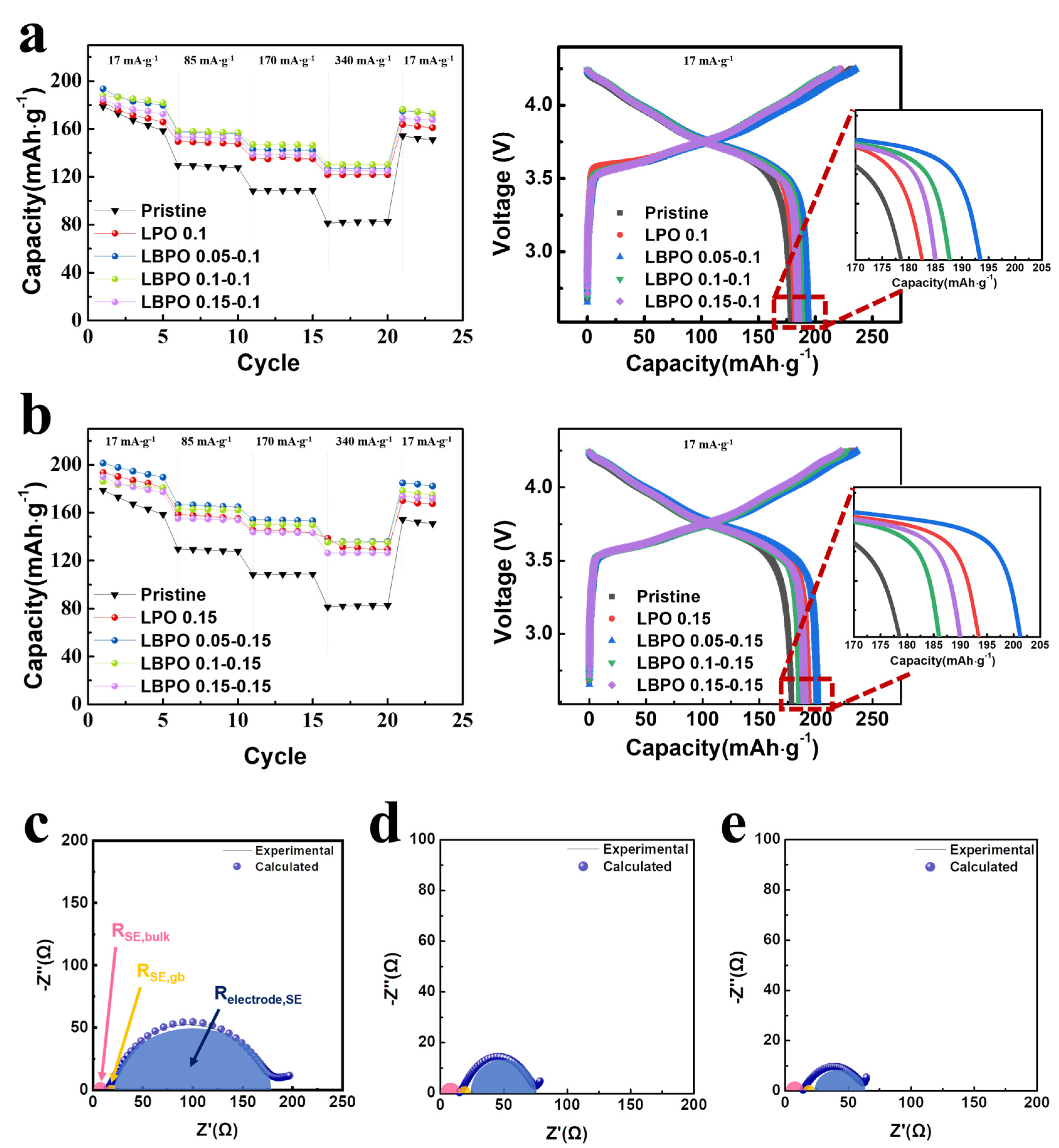
Figure 1. Discharge capacities at current densities of 17, 85, 170, and 340 mA·g−1 for the pristine NCM and (a) LPO 0.1-, LBPO 0.05–0.1-, LBPO 0.1–0.1-, and LBPO 0.15–0.1-coated NCMs; (b) LPO 0.15-, LBPO 0.05–0.15-, LBPO 0.1–0.15-, and LBPO 0.15–0.15-coated NCMs. Right side of the figure shows the initial charge–discharge curves obtained in the left figure. Nyquist plots of the ASSCs containing (c) pristine, (d) LPO 0.15-coated, and (e) LBPO 0.05–0.15-coated NCMs.
Batteries 09 00292 g001
Figure 2. SEM (left) and TEM (right) images of the (a,d) pristine, (b,e) LPO 0.15-coated, and (c,f) LBPO 0.05–0.15-coated NCMs powders. Right of the TEM images (g,h) are the XPS spectra obtained from the left samples.
Batteries 09 00292 g002
Figure 3. S 2p XPS profiles of the composite electrodes containing (a) pristine NCM before the test, (b) pristine NCM after 100 cycles, and (c) LBPO 0.05–0.15-coated NCM after 100 cycles; P 2p XPS profiles of the composite electrodes containing (d) pristine NCM before the test, (e) pristine NCM after 100 cycles, and (f) LBPO 0.05–0.15-coated NCM after 100 cycles.
Batteries 09 00292 g003
Figure 4. Cross-sectional STEM image (left) and EDS line profile (right) of the pristine NCM before the test.
Batteries 09 00292 g004
Figure 5. Cross-sectional STEM image (left) and EDS line profile (right) of the pristine NCM after 100 cycles at a current density of 170 mA·g−1.
Batteries 09 00292 g005
Figure 6. Cross-sectional STEM image (left) and EDS line profile (right) of the LBPO 0.05–0.15-coated NCM after 100 cycles at a current density of 170 mA·g−1.
Batteries 09 00292 g006
Figure 7. Schematic illustration presenting the effect of LBPO coating.
Batteries 09 00292 g007
Table 1. Discharge capacities of the pristine and LPO- and LBPO-coated NCMs at current densities of 17, 85, 170, and 340 mA·g−1, their Coulombic efficiencies at 17 mA·g−1, and their capacity retentions.
SamplesDischarge Capacity (mAh·g−1)Coulombic Efficiency, η (%)Capacity Retention (%) *
17 mA·g−1
(1st Cycle)
85 mA·g−1
(7th Cycle)
170 mA·g−1
(12th Cycle)
340 mA·g−1
(17th Cycle)
Pristine178.7129.3108.882.176.3745.94
LPO 0.1 coated182.6149.1134.9121.882.2266.70
LPO 0.15 coated193.6157.8145.1131.282.7467.77
LBPO 0.05–0.1 coated193.6157.4142.7126.982.2865.55
LBPO 0.1–0.1 coated187.7158.2147.0130.485.6369.47
LBPO 0.15–0.1 coated185.1153.2138.8125.283.7967.64
LBPO 0.05–0.15 coated201.4166.4154.1135.885.2767.43
LBPO 0.1–0.15 coated186.0162.9150.2135.481.7972.80
LBPO 0.15–0.15 coated190.0154.9143.7126.585.5566.58
* Capacity retention is defined as the percentage of capacity retained at 340 mA·g−1 compared to that at 17 mA·g−1.
Table 2. Impedance values calculated from the fitting for the pristine, LPO 0.15-coated, LBPO 0.05–0.15-coated NCMs.
SamplesImpedance Values
RSE,bulk (Ω)RSE,gb (Ω)Relectrode/SE (Ω)Rtotal (Ω)
Pristine14.59.4165.3189.2
LPO 0.15 coated15.39.251.776.2
LBPO 0.05–0.15 coated14.38.340.162.7
Disclaimer/Publisher’s Note: The statements, opinions and data contained in all publications are solely those of the individual author(s) and contributor(s) and not of MDPI and/or the editor(s). MDPI and/or the editor(s) disclaim responsibility for any injury to people or property resulting from any ideas, methods, instructions or products referred to in the content.

