Article

Crosslinked Hyperbranched Polyglycerol-Based Polymer Electrolytes for Lithium Metal Batteries

1
Fraunhofer Institute for Manufacturing Technology and Advanced Materials, Wiener Straße 12,28359 Bremen, Germany
2
Department 2 Biology/Chemistry, University of Bremen, Leobener Straße 3, 28359 Bremen, Germany
*
Author to whom correspondence should be addressed.
Batteries 2023, 9(9), 431; https://doi.org/10.3390/batteries9090431
Submission received: 14 July 2023 / Revised: 9 August 2023 / Accepted: 18 August 2023 / Published: 23 August 2023
(This article belongs to the Special Issue Advanced Electrolytes for Metal Ion Batteries)

Abstract

:
Tailored partially methylated and methacrylated hyperbranched polyglycerols (hbPG-MAx/OMey) combined with lithium bis(trifluoromethanesulfonyl)imide (LiTFSI) as conducting salt were investigated after crosslinking with respect to their application as solid polymer electrolytes (SPE) in lithium metal batteries. For sample preparation and coating, a straightforward solvent-free photopolymerization method was applied. With the aim of finding the right balance between mechanical and electrochemical properties, electrolytes with different crosslinking densities were studied. High crosslink density increases mechanical integrity but reduces local chain motion and thus ionic conductivity at the same time. Differential scanning calorimetry (DSC), chronoamperometric and impedance measurements show that the hyperbranched polyether structure interacts strongly with lithium cations. Finally, the SPE with the lowest crosslinking density was selected and investigated in cycling tests due to the parameters of highest absolute values in conductivity (2.1 × 10⁻⁶ S cm−1 at 30 °C; 2.0 × 10⁻⁵ S cm−1 at 60 °C), lowest Tg (from DSC: −39 °C), electrochemical stability window (4.3 V vs. Li/Li+) and mechanical strength (1.6 ± 0.4 MPa at 25 °C). At low C-rates and elevated temperatures (60 °C), cells were cycled with high Coulombic efficiency. At high C-rates, a distinct decrease in specific capacity was observed due to insufficient ionic conductivity.

Graphical Abstract

1. Introduction

Electric mobility represents the key technology to replace fossil fuels and reduce CO2 emissions. The ambition to push the electric mobility market requires increasing research efforts in energy storage technologies in order to realize innovative battery concepts [1,2,3]. Therefore, innovative material concepts for lithium metal battery (LMB) technologies are currently in the interest of research in terms of energy density, lifetime efficiency, operating temperature range, charge/discharge cycling, safety properties, ruggedness and production simplification as well as cost reduction [1,3,4,5,6,7,8]. Lithium ion batteries (LIBs), or lithium secondary batteries, are already used in a wide range of applications, e.g. for communication as well as consumer electronics, electric vehicles and electrochemical energy storage [1,2,3,4,6,7,8].
The utilization of lithium metal in LMBs as anode material combined with high-energy cathode materials are required due to an aspired energy density maximization [4,6,8,9]. In particular, the application of metallic lithium as anode material is beneficial due to its high theoretical specific capacitance (lithium metal 3860 mAh g−1 vs. graphite 372 mAh g−1) and low negative electrochemical potential (−3.04 V vs. SHE) [9]. Today’s commercial LIBs with graphite anodes usually use aprotic organic liquid electrolytes containing toxic, volatile and flammable compounds [4,7,10,11,12,13]. Accordingly, safety issues such as fire, explosions and leakage can be associated with liquid electrolytes [7,10,11,13]. In contrast to commercial liquid electrolytes, solvent-free solid polymer electrolytes (SPEs) represent a promising class of materials [7,8,14,15], along with sulfides and oxides [5,16,17], since they can be employed in a high-energy lithium metal-based all-solid-state battery (ASSB) [5,7,14]. In addition to lithium metal compatibility, SPEs offer enhanced resistance to variations in the volume of the electrodes during charge/discharge processes, improved safety features and excellent flexibility and processability [7,8,14].
Justified by the ability to solvate and transport Li+ ions, a variety of studies in the scientific literature reporting on SPEs focused on polyethylene oxide (PEO)-based materials [7,14,18]. Similar to crownethers coordinating metal cations, the oxygen atoms along the PEO backbone can interact with Li+ ions [7,12,14,19,20,21]. Below the melting temperature (Tm ≈ 65 °C) [13,15], the ionic conductivity of a thermoplastic PEO-based SPE is limited (~10−7 S cm−1 at RT) [8,12] due to its semicrystalline nature [12,13,14,15]. Many efforts have been made to reduce the crystallinity and optimize mechanical properties by adding additives [22,23,24,25,26] or by derivatization [12,13,27,28,29]. In addition, a remarkable diversity of alternative polymer host materials have been studied, such as polycarbonates, polyesters, polynitriles, polyalcohols, polyamines and poly(meth)acrylates [7,14,18]. However, material specific drawbacks like insufficient ionic conductivity, especially at ambient temperature, or poor mechanical stability, hamper large scale commercialization of SPEs [7,14,18]. Polymer electrolytes are prepared frequently by casting followed by evaporation of organic solvents, which is unsuitable for large-scale industrial manufacturing [10]. An ideal strategy for mass production is therefore a solvent-free approach. Demonstrated by Wang et al., a monofunctional poly(ethylene glycol) methyl ether methacrylate (PEGMEM) was mixed with lithium bis(trifluoromethanesulfonyl)imide (LiTFSI) to form a homogeneous precursor solution in a solvent-free approach [10]. After an extended period of UV polymerization, a SPE was formed with a comb-like polymer structure, named poly-PEGMEM. In dependence of the chain length of the linear PEO side chain moiety, the investigated electrolyte presents a comparatively high conductivity of 1.44 × 10⁻⁴ S cm−1 at 30 °C and excellent compatibility with metallic lithium as well as a wide electrochemical window (5.1 V vs. Li/Li+ at 60 °C). However, our own attempts to reproduce the poly-PEGMEM-based polymer electrolyte system showed a lack of mechanical strength. Moreover, the concept of solvent-free polymerizable polymer electrolytes was addressed in two preceding studies. Nishimoto et al. copolymerized ethylene oxide (EO) and 2-(2-methoxyethoxy)ethyl glycidyl ether (MEEGE) and esterified terminal hydroxyl groups with acrylic acid to obtain polymerizable macromonomers with branched side chains [30]. Mixtures of synthesized macromonomers, dissolved lithium salt and photoinitiator were used to form solvent-free polymer electrolytes after photopolymerization. Continued by Watanabe et al., polymer network electrolytes with dissolved lithium salt were prepared by reaction of crosslinkable macromonomers with branched ether side chains [31]. The macromonomers were synthesized by copolymerization of EO and MEEGE in the presence of diglycerol to yield branched polyether tetraols. The tetra-functional polyol was modified by partial methoxyethylation followed by acrylation of the remaining hydroxyl groups. The ionic conductivity of crosslinked polymer electrolytes was dependent on the Li+ salt content, molecular weight and the extent of methoxyethylation or crosslink density.
Highly branched, dendritic, star- or comb-like polymer structures were attributed to pronounced local segmental motion due to the amorphous state [7,10,12,13,18,27,32,33,34]. The concept of hyperbranched polymer electrolytes and their lack of crystallinity was introduced by Hawker et al. in the year 1996 [35], which studied a series of branched electrolytes based on linear oligomeric PEO and phenyl units. Subsequently, attempts were carried out to utilize hyperbranched polyglycerol (hbPG) and their derivatives as a matrix for Li+ ions [32,36,37,38,39,40]. The polymer architecture of highly functional hbPG coupled with the ability to complex Li+ ions by coordinating groups on the polymer chain as well as to solve high levels of salt turned out to be a promising electrolyte material [32,36,37,38,39,40].
However, the many terminal hydroxyl groups from the hbPG structure have proven to be a disadvantage. The hydrogen bonds between the OH groups increase the Tg considerably and the OH groups themselves are not electrochemically stable during the redox cycle in a LMB [32]. Taking this into account, Kim et al. presents a fully methylated hbPG electrolyte [32]. The synthesized methylated polymer exhibited low Tg (−72 °C) compared to unmodified hbPG (Tg: −17 °C). Using lithium trifluoromethanesulfonate (CF3SO3Li) as conducting salt, an ion conductivity of 1.03 × 10⁻⁵ S cm−1 at 30 °C was obtained with a Li/O ratio of 1:20. Generally, the absence of crystalline or rigid segments in branched polyether-based polymers results in low mechanical strength, which is reflected in viscous to fluid behaviour [34,41].
The combination of hbPG structures, multifunctional end-group capping and crosslinking could be an approach for a novel SPE. Three-dimensionally crosslinked polymer structures exhibit high mechanical stability compared to their noncrosslinked counterparts [42,43,44]. They can act as a separator to insulate the positive electrode from the negative electrode and could be a solution to minimize or suppress problematic lithium dendrite growth [7,16,43].
With this background, a novel SPE based on photopolymerizable partially methylated and methacrylated hyperbranched polyglycerol (hbPG-MAx/OMey) was investigated in this work. In our previous studies, the polymer architecture was designed by the molecular mass, branching degree as well as end group functionality [41,45]. The mechanical stability was varied by crosslinking via tailored methacrylate substitution. So far, the utilization of such macromolecular structures in LIBs as well as the correlation between the degree of crosslinking and electrochemical properties are unknown. The focus of this work is to understand the structure–property relationship of modified hbPG-based polymer electrolytes and in this context addresses the following issues: Effect of polymer functionality towards (i) conductivity, (ii) chemical stability against metallic lithium, (iii) mechanical stability while maintaining high chain mobility, and (iv) charge/discharge cycling performance using lithium metal as an anode material.

2. Experimental Part

2.1. Materials

The following reagents and materials were used as received: 2,2-Dimethoxy-2-phenylacetophenone (DMPA, ≥98.0%, TCI Deutschland GmbH, Eschborn, Germany), lithium bis(trifluoromethanesulfonyl)imide (LiTFSI, 99.9%, Solvionic, Toulouse, France) was dried in vacuum at 120 °C for 16 h before use, WhatmanTM glass microfiber filter (Grade GF/A, GE Healthcare Life Sciences, Little Chalfont, United Kingdom) was dried in vacuum at 80 °C for 16 h before use, and Li-foil (150 µm) from Albemarle U.S. Inc. (Kings Mountain, NC, USA). Lithium iron phosphate (LFP) cathodes with an active material content of 77 wt.% were prepared as follows: LFP (Clariant, Muttenz, Switzerland), polyvinylidene difluoride (PVDF, 11.5 wt.%, Solef® 5130, Solvay, Hannover, Germany) and carbon black powder (11.5 wt.%, Super C65, Timcal, Bodio, Switzerland) mixed in N-methyl-2-pyrrolidone (NMP, >99%, Sigma-Aldrich, Taufkirchen, Germany). Hereafter, the slurry was doctor-bladed onto Al foil. After drying and calendering, the thickness of the cathode without the Al foil was about 20 µm.

2.2. Methods

FTIR Fourier-transform infrared spectroscopy (FTIR) spectra were recorded on a Bruker ALPHA II series spectrometer equipped with an ALPHA‘s Platinum ATR single reflection diamond ATR module in a wavelength range between 4000 and 400 cm−1. All spectra were measured with a resolution of 2 cm−1 and 32 scans. Bruker OPUS software (version 8.1) was used to process the data.
DSC Differential scanning calorimetry (DSC) analysis were performed using a TA Instruments Discovery DSC under N2 atmosphere. The temperature range was set from −90 °C to 100 °C with a heating rate of 20 K min−1 in the first and second run, respectively. The glass transition temperature (Tg) was determined from the maximum of the first derivative of heat flow during the first heating. TA Instruments TRIOS software (version 4.5.0) was used for evaluation.
XRD X-ray diffraction (XRD) were performed on a Rigaku MiniFlex 600 diffractometer with Cu Kα radiation (λ = 1.54 Å). Diffraction data were collected with a step width of 0.05° in the 2θ range from 5° to 80° and a measurement time of 2 s per step. Both a glass sample holder and an Al target in an inert sample chamber were used.
DMA Dynamic mechanical analysis (DMA) were carried out with a DMA Q800 from TA Instruments via single cantilever mode. The measurements were performed in a temperature range from −90 °C to 100 °C, with a frequency of 1 Hz, an amplitude of 20 μm and a heating rate of 2 K min−1. The size of specimens used was 25 × 5 × 2 mm3. The data were processed with the TA Instruments software TRIOS (version 4.5.0).
EIS For the determination of the temperature-dependent ionic conductivity, glass microfiber filters (WhatmanTM, ⌀ = 18 mm) infiltrated with liquid polymer electrolyte (LPE, see Section 2.3.4) or stainless steel (SS) electrodes (⌀ = 18 mm) coated with solid polymer electrolytes (SPE, see Section 2.3.5) were placed between SS blocking electrodes ((SSǀLPEǀSS) or (SSǀSPEǀSS)) in an El-Cell® ECC-Std test cell. Electrochemical impedance spectroscopy (EIS) was performed with a Gamry Instruments Interface 1010E Potentiostat between −20 °C and 80 °C with an amplitude of 10 mV in a frequency range of 1 MHz to 1 Hz. After the measurement, the specific thickness of the SPE layer was determined. The data were evaluated using ZView® software (version 3.3a). The ionic conductivity σ was calculated using Equation (1):
σ = L / S × R
where L is the thickness of electrolyte layer, R is the bulk resistance of polymer electrolyte and S is the contact area of electrode and electrolyte. The average value of σ was calculated from three measurements.
LSV Linear sweep voltammetry (LSV) was recorded between −0.5 and 7 V vs. Li/Li+ with a scan rate of 1 mV s−1 to determine the electrochemical stability window of the SPE. The LiǀSPEǀSS cell was tested at 60 °C.
tLi+ The Li+ transference number (tLi+) was obtained by using chronoamperometric and impedance spectroscopic measurement using symmetric cells with a LiǀSPEǀLi setup. For the potentiostatic polarization, a voltage of 10 mV was applied during the polarization step. The steady-state current was reached after 16 h of polarization at 60 °C. The voltage and frequency parameters for the initial and steady-state EIS measurements were taken from conductivity measurements. The electrolyte resistances were determined with a frequency range between 1 MHz and 0.1 Hz before and after polarization. According to a report by Evans, Vincent and Bruce for polymer electrolytes [46] with mobile cations and anions, tLi+ was calculated using Equation (2):
t Li + = I SS Δ V I 0 R 0 / I 0 Δ V I SS R SS        
where I0 is the initial current, Iss the steady-state current, ΔV the applied potential, R0 and Rss the electrode resistances before and after polarization, respectively.
Galvanostatic Cycling The constant current cycling tests were performed using a coin cell (CR2032) with a LiǀSPEǀLFP setup. To avoid short circuits, cells were assembled with a SPE-coated cathode (see Section 2.3.5) with a diameter of 16 mm and a smaller Li metal anode (⌀ = 15 mm). Two SS spacers (thickness: 2 × 0.5 mm) were used to ensure contact with the coin cells case. Cells were charged and discharged at 30 °C and at 60 °C using the BaSyTec battery test system in the potential range between 2.5 and 3.9 V vs. Li/Li+. The actual usable capacity of the LFP cathode in each cell was adjusted and set after up to three cycles at C/10. The cyclization with different C-rates was performed with five cycles each at C/10, C/5, C/2, 1C and C/10 again. The equilibrium period between the change of the different C-rates was 15 h. Specific capacity were calculated based on the weight of the active material (⌀ = 16 mm). Long-term cyclization was performed with C/10 at 60 °C. The data were processed using BaSyTec software (version 6.2.29.0).

2.3. Polymer Electrolyte Preparation

2.3.1. Partially Methylated and Methacrylated Polyglycerols

Three viscous, partially methylated and methacrylated hbPG prepolymers (hbPG-MA0.26/OMe0.74) 3a, (hbPG-MA0.13/OMe0.87) 3b and (hbPG-MA0.05/OMe0.95) 3c were obtained in a three-step synthesis procedure from our previous study [45]. The hbPG based on 1,1,1-tris(hydroxymethyl)propane (TMP) with an initiator/monomer ratio of 1:40 was mixed with different aliquots of dimethyl sulfate (DMS) (1.0 eq., 1.2 eq., and 1.4 eq. per OH group, respectively), in three separate methylation reaction mixtures. The following methacrylation of residual hydroxyl groups was carried out with methacrylic anhydride (MAAH), triethylamine (TEA) and 4-dimethylaminopyridine (DMAP).

2.3.2. Fully Methylated Polyglycerol

Liquid methylated hbPG (hbPG-OH0.02/OMe0.98) 3d (polymer No. 9) originated from a previous study [41]. The fully methylation of hbPG 1 was carried out in a two-step synthesis approach. Accordingly, the hbPG based on TMP as initiator and glycidol as monomer was used with an initiator/monomer ratio of 1:40. DMS was used as alkylating agent (1.6 eq. per OH group) in the reaction mixture during methylation.

2.3.3. Preparation of Polymer Electrolyte Mixtures

Firstly, the polymers 3a3d were predried under compressed air flow using synthetic air and mechanical mixing. The following preparation steps were performed in an argon-filled glove box (H2O, O2 < 0.1 ppm, MBraun). Each polymer (2.000 g) was mixed with finely ground lithium bis(trifluoromethanesulfonyl)imide (LiTFSI) (0.627 g for 3a+LiTFSI, 0.635 g for 3b+LiTFSI, 0.641 g for 3c+LiTFSI, 0.644 g for 3d+LiTFSI) by mechanical stirring to form a homogeneous solution (Li:O = 1:20, approx. 24 wt.% LiTFSI depending on oxygen atom content of the prepolymers, EO backbone oxygen as well as ester oxygen were considered in the calculation). After stirring for 16 h at 50 °C, the electrolyte solution 3d+LiTFSI was completed. In contrast, the prepolymer-salt mixtures were stirred at 50 °C for 16 h under exclusion of light. Then, 1.0 wt.% 2,2-dimethoxy-2-phenylacetophenone (DMPA) (0.020 g) (related to the prepolymer mass) as photoinitiator was added to each of prepolymer–salt solutions and the mixture was stirred for additional 2 h to obtain the final precursor electrolyte solutions 3a+LiTFSI, 3b+LiTFSI and 3c+LiTFSI.

2.3.4. Liquid Electrolyte

For impedance measurements, glass microfiber filter (WhatmanTM, ⌀ = 18 mm) were infiltrated with the prepared liquid electrolyte solution 3d+LiTFSI. The soaked separator was placed between two stainless steel (SS) electrodes (⌀ = 18 mm) for measurements.

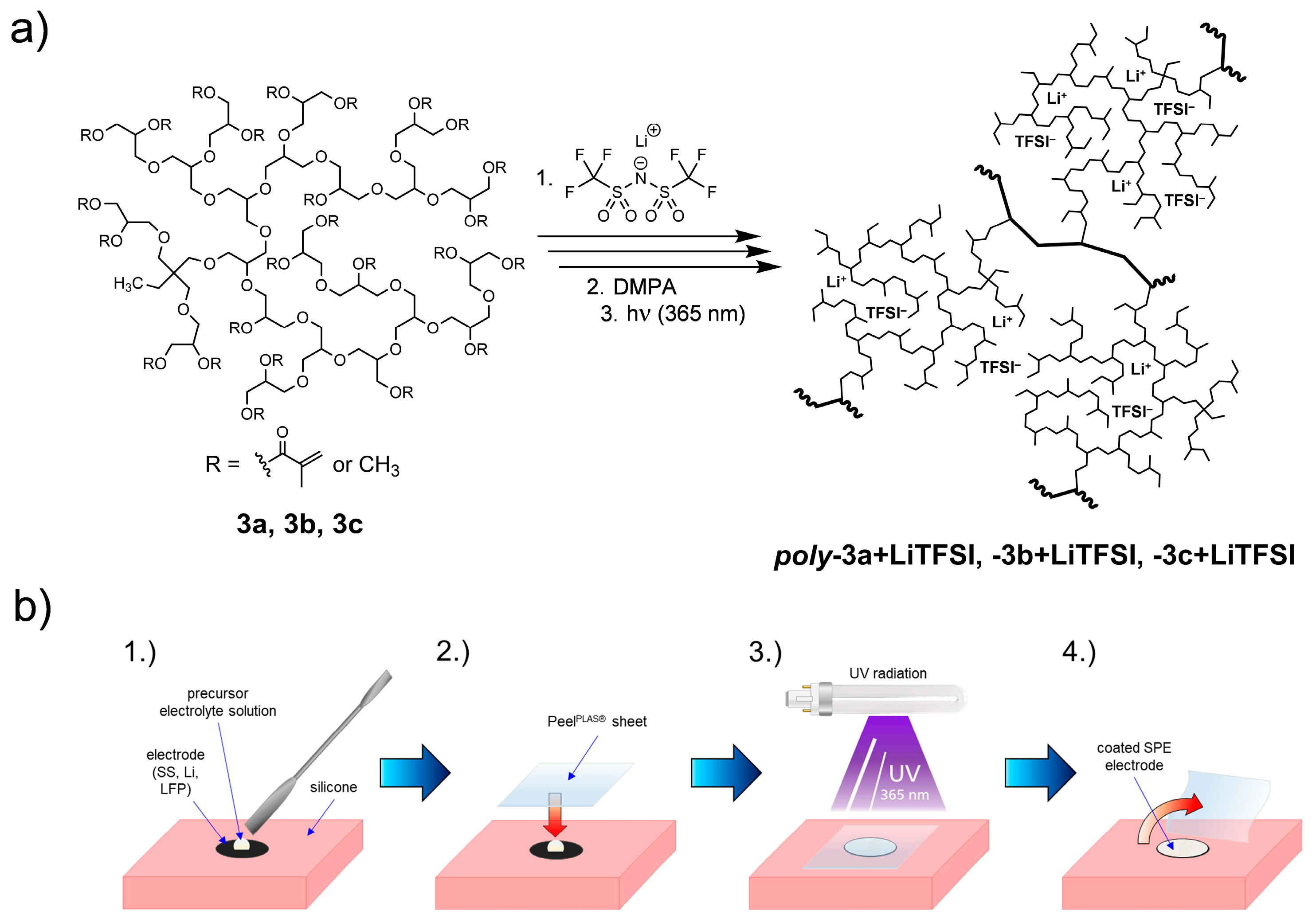
2.3.5. Electrode Coating via Photopolymerization

The viscous precursor electrolyte solutions 3a+LiTFSI, 3b+LiTFSI and 3c+LiTFSI were each applied dropwise on different electrode types (SS, ⌀ = 18 mm; Li, ⌀ = 17 mm; LFP, ⌀ = 16 mm) (approx. 0.08 g electrolyte per electrode). A nonadhesive silicone pad served as a work surface. To create a smooth and uniform surface, a 50 µm PeelPLAS® sheet [47] based on a PA66 film with a plasmapolymeric release layer was placed on top of the electrode. The viscous precursor electrolyte was evenly distributed on the electrode surface and polymerized for 3 min under a conventional nail UV lamp (0.7 W cm−2 (measured with BTS256-UV from Gigahertz-Optik), 99N-UVL1 distributed by 99nails—Cura GmbH) with a wavelength of 365 nm. The PeelPLAS® sheet was peeled off and the overflowed electrolyte was removed to obtain the final coated SPE electrodes. The SPE layer thicknesses ranged from 200 µm to 400 µm on SS, Li and LFP.
Crosslinked, partially methylated and methacrylated polyglycerol electrolytes containing LiTFSI as conducting salt (poly-hbPG-MAx/OMey+LiTFSI) are designated as poly-3a+LiTFSI, poly-3b+LiTFSI and poly-3c+LiTFSI, respectively.

2.3.6. Preparation of DMA Specimens

The viscous precursor electrolyte solutions 3a+LiTFSI, 3b+LiTFSI and 3c+LiTFSI were poured into silicone molds with dimensions of 25 × 5 × 2 mm3. The PeelPLAS® sheet was placed on top of the mold. Then, the specimens were polymerized for 8 min under the UV lamp, demolded, turned 180°, and exposed to the UV beam for an additional 2 min.

3. Results and Discussion

3.1. Preparation of SPEs

The electrochemical investigations are based on our preliminary work of two studies, in which the synthetic route (see Section 2.3.1 and Section 2.3.2) of the present polymers and their chemical structure and properties have already been discussed in detail [41,45]. With the intention of forming a solid polymer electrolyte (SPE) in a solvent-free approach (see Figure 1a), the polymeric structure was adjusted to be applied in a Li-metal cell. As known from previous studies, hyperbranched polyglycerols (hbPGs) have a highly flexible aliphatic polyether backbone, multiple functional groups as well as an amorphous structure with no crystalline component [48,49,50,51]. These properties could provide a versatile and beneficial scaffold for a SPE. As known from the literature, reducing the glass transition temperature (Tg) to enhance the segmental chain mobility is one of the simplest and most effective ways to improve ionic conductivity [8,14,18]. With the intention of lowering the Tg to improve segmental motion of polymer chains, an approach for partial methylation of the hbPG end groups was described in our previous study [41].
In addition, this type of modification achieves improved compatibility with lithium metal [32]. Based on this, polymerizable methacrylate groups were incorporated into the macromolecular structure in our second follow-up study [45] to ensure mechanical stability. The degree of crosslinking was tailored via the proportion of crosslinker groups within the macromolecule.
Adapted without further changes, the fully methylated hbPG polymer (hbPG-OH0.02/OMe0.98) 3d from our first study [41] and the three various crosslinkable, partially methylated and methacrylated hbPG prepolymers (hbPG-MA0.26/OMe0.74) 3a, (hbPG-MA0.13/OMe0.87) 3b and (hbPG-MA0.05/OMe0.95) 3c from our second study [45] with varied degrees of methacrylate substitution (DS) were used and tested in this work as polymer electrolytes.
To achieve efficient interfacial contact between SPE and cathode material, the different types of electrodes were coated with polymer electrolytes via solvent-free in situ polymerization. As shown in Figure 1b, the viscous precursor electrolyte solutions 3a+LiTFSI, 3b+LiTFSI and 3c+LiTFSI were applied on the electrode surface and polymerized under UV radiation using a common photoinitiator (DMPA) and a PeelPLAS® release sheet. The release sheet was needed to create a smooth and uniform SPE surface. Due to the formation of a three-dimensional network, the SPE films were mechanically stable, so no additional separator was required for cell assembly. However, the liquid electrolyte solution 3d+LiTFSI without implemented methacrylate groups and subsequent lack of mechanical stability could only be used in combination with a glass microfiber separator served as a reference for the conductivity measurements.

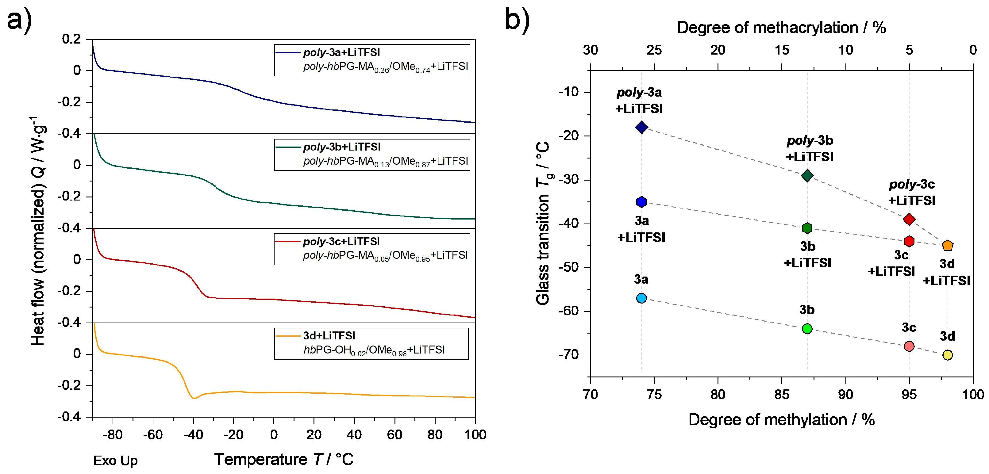
3.2. Structural and Thermal Analysis of SPEs

After UV polymerization of the precursor solutions, a slight decrease in the C=C band at ν = 1637 cm−1 and a minor shift of the C=O band from ν = 1718 cm−1 to ν = 1725 cm−1 is observed for the poly-3a+LiTFSI, -3b+LiTFSI and -3c+LiTFSI samples in the FT-IR spectra (see Supplementary Materials—Figure S1), indicating that methacrylate groups reacted. Details regarding the molecular structure, crosslinking and the resulting formation of a three-dimensional network of poly-hbPG-MAx/OMey have already been discussed previously [41,45]. For the polymer electrolytes, a possible Li+ coordination to the carbonyl oxygen and an associated shift of this band to lower wavenumbers due to a lower electron density could not be observed [52,53]. In contrast, the C-O-C ether band is strongly affected by cation complexation. However, the corresponding signals are in a superimposed region of absorption by the TFSI anion. The peak intensities between ν = 1352 cm−1 and ν = 1055 cm−1 are consistent with dissociated TFSI anions [12,54,55]. All in all, these observations suggest virtually no interaction between Li+ and the C=O carbonyl group, but LiTFSI interacts strongly with the ether side chains of the hbPG backbone. Furthermore, it should be noted that both the precursor solutions as well as the SPEs were found to be sensitive to trace amounts of water. Similar to PEG, pure hbPG-MAx/OMey has a tendency to absorb water. In presence of hygroscopic LiTFSI, samples outside the glovebox rapidly absorbed moisture from the air as indicated by an increase in the OH band over time.
DSC thermograms of the pure prepolymers 3a3c and fully methylated polymer 3d without additives have already been examined [41,45]. All thermograms described below indicate an amorphous character and show a monotonic decrease of the Tg with increasing DM (see Figure 2a; Supplementary Information—Figure S2).
It should be noted that the XRD experiment (see Supplementary Information—Figure S3) also confirms the amorphous nature of the crosslinked SPE poly-3c+LiTFSI, as no sharp Bragg reflections can be identified in the diffractograms starting from the polymer electrolyte. The addition of lithium conducting salt (Li:O = 1:20) significantly increases the Tg of the respective precursors 3a+LiTFSI, 3b+LiTFSI, 3c+LiTFSI or polymer electrolyte solution 3d+LiTFSI (see Table 1; Figure 2b). Compared to the polymers without salt addition, a Tg increase between 22 °C to 25 °C was observed for the electrolytes. This concentration-dependent phenomenon can be explained by the fact that coordinated lithium ions act as a noncovalent crosslinker by complexing with two or more polyether chains [7,12,14,19,20,21]. Accordingly, the mobility of the polymer chains is reduced. After photopolymerization of the precursors, the Tg of the respective SPE species poly-3a+LiTFSI, -3b+LiTFSI and -3c+LiTFSI shifts to higher temperatures. The crosslinking and the change of macromolecular structure leads to the formation of bulky, inflexible polymer chains associated with a decrease in chain mobility and free volume, resulting in a further increase in Tg [31,44,45,56]. Among the three studied SPEs, poly-3c+LiTFSI has the lowest crosslinking density and thus shows the lowest Tg (−39 °C).

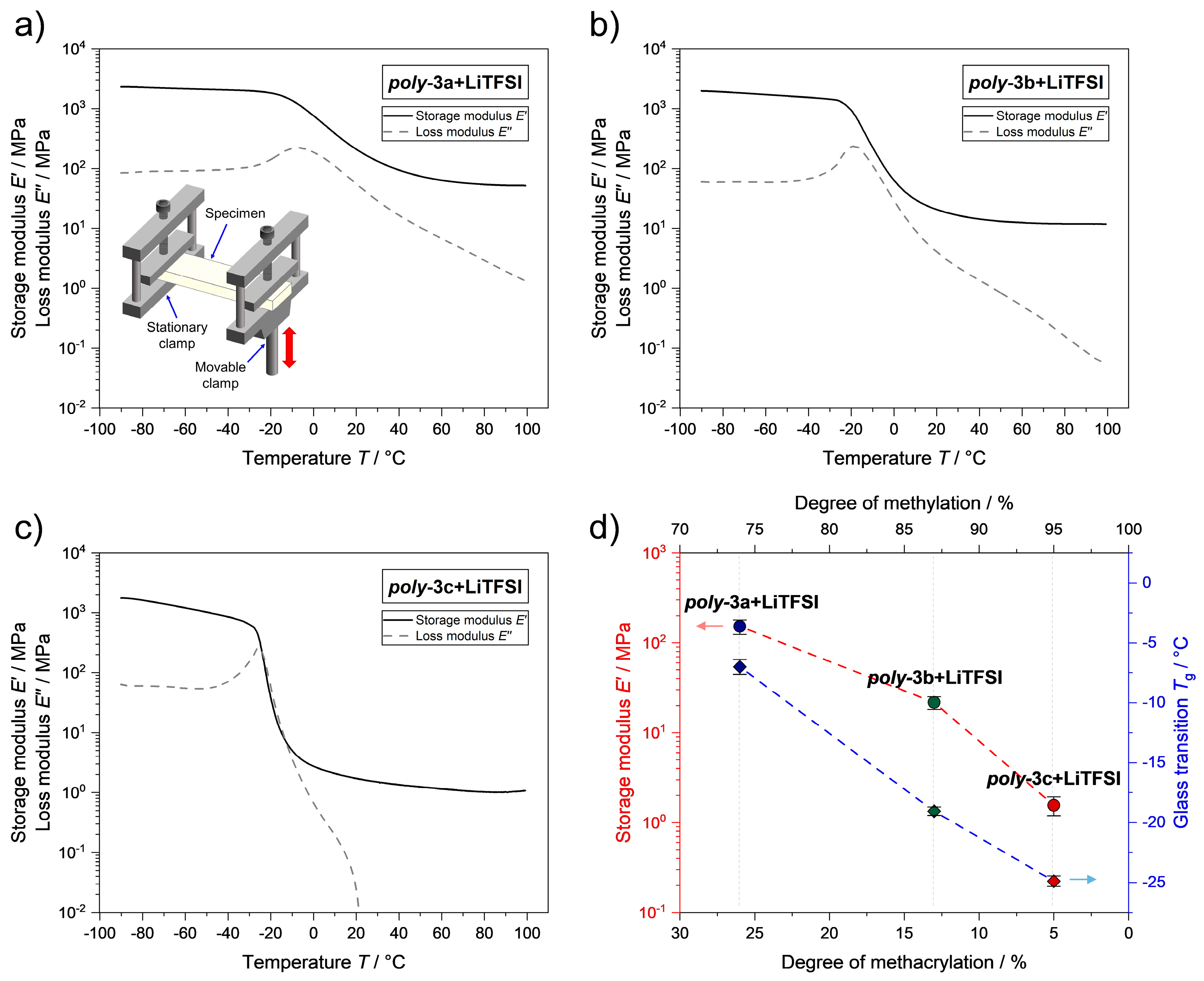
3.3. Mechanical Properties

Towards the goal of creating a mechanically stable separator layer that resists volume changes and prevents the growth of lithium dendrites during long cycle processes, the mechanical properties of the crosslinked SPEs were examined with DMA. The DMA results (see Figure 3) demonstrate that the SPE properties after curing were correlated to the average number of methacrylate groups per macromolecule. As described in our previous study, the higher the degree of crosslinking groups within the precursor macromolecules, the higher the crosslink density after polymerization, which is also reflected in stiffness of the resulting specimens [45]. Interestingly, the measured magnitudes of the storage moduli of the SPEs did not change essentially compared to the storage moduli of the crosslinked polymers without LiTFSI [45]. The compensating effect of an expected reduction in crosslink density due to the addition of an additive salt with simultaneous complexation of polymer segments by Li+ in the context of stiffening and Tg increase could be an explanation. DMA plots of selected poly-3a+LiTFSI, -3b+LiTFSI and -3c+LiTFSI samples with the storage modulus (E′) as well as loss modulus (E″) against temperature are shown in Figure 3a–c. The maximum of the loss modulus-temperature curves was used for the determination of the Tg (see Table 1, Figure 3d). The DMA curve shape reflects the variation of the three-dimensional network densities as well as the mechanical strength depending on the DS of the respective macromolecular precursor.
As shown in Figure 3d and Table 1, SPEs with a higher degree of DS have a higher crosslink density after curing and consequently a higher E′. At the same time, a higher crosslinking density ensures an increase in Tg. E″ provides information about the viscous response of a material associated with the amount of energy dissipated in the sample. For the poly-3c+LiTFSI samples with the lowest DS, the DMA results revealed that E″ exceeds E′ between −24 °C to −13 °C during the measurements (see Supplementary Information—Figure S4). This observation indicates a domination of ideal-viscous to viscoelastic property (E″ > E′; tan δ > 1), suggesting a liquid-like behaviour of the solid polymeric system [45].
Nevertheless, poly-3c+LiTFSI is not a liquid, since the slightly three-dimensional intermolecular methacrylate linkage provides wide-mesh long-range order. At elevated temperatures above 20 °C, a nearly constant E′ and a very low E″ were observed in poly-3c+LiTFSI samples, indicating an almost purely elastic behaviour (E″ << E′). As the material is deformed and bond angles change along the chains, entropy decreases as fewer conformations are available. In contrast to the observed stiffness in poly-3c+LiTFSI samples, this principle follows the theory of rubber elasticity. According to this, polymeric chains in low crosslinked networks can be considered as an entropic spring [57]. The poly-3c+LiTFSI electrolyte combines characteristics of solids and liquids.
According to an approach from the literature, electrolytes with high elastic modulus can effectively suppress the growth of lithium dendrites [16,43,58]. Monroe and Newman demonstrated in their kinetic model that the shear modulus (G) should be above 7 GPa to physically inhibit lithium dendrite formation, which modulus is about twice that of metallic lithium [59]. Contrary to theoretical predictions, crosslinked polyethylene/poly(ethylene oxide)-based SPEs with low modulus (G ≈ 0.1 MPa) show remarkable resistance to dendrites growth [43].
These and other studies suggest that high modulus alone is not a requirement for dendrite growth control [16,43,58]. With our data, an estimation of G is possible according to Equation (3) [60] using the Young’s modulus (E) from the linear elastic range via an oscillating bending measurement (Ef) (or a tensile test (Et)), if a Poisson’s ratio (µ) is assumed in the corresponding temperature interval (see Supplementary Information—Table S1).
G = E / 2 1 + μ
Typically, polymers have a µ, which refers to the deformability under stress, in the range of 0.3 for hard and 0.5 for soft materials, such as rubbery materials [61]. Following Equation (3), the G values of the studied SPEs are about three times smaller than the experimentally determined E′ values. Contrary to the postulated requirements [59] and the maintenance of high elasticity, G in the order of GPa appears to be inaccessible to polymer-based electrolytes.

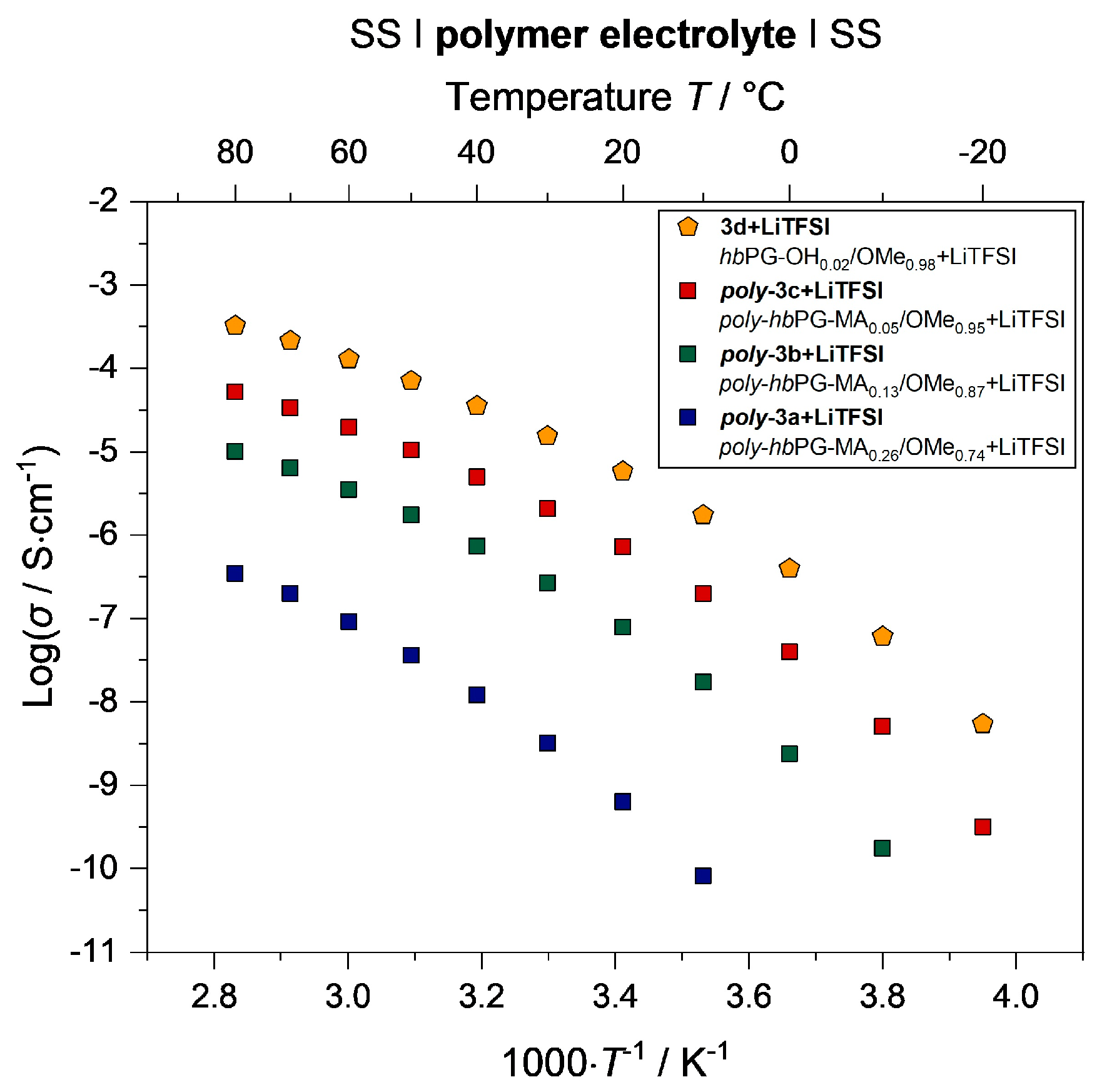
3.4. Electrochemical Properties

The Nyquist plots of poly-3c+LiTFSI at various temperatures exhibit one semicircle up to the maximum measured frequency (see Supplementary Information—Figure S5). The same behaviour was observed for all prepared polymer electrolytes. The semicircle is attributed to the sample bulk resistance that can be fitted using a combination of resistive (R) and capacitive (CPE) elements, while the straight line in the low frequency region is the result of charge diffusion at the two blocking stainless steel electrodes [21,62,63].
The Arrhenius plots in Figure 4 show the conductivities calculated from the fitted bulk resistances for all four studied hbPG-based electrolytes with different degrees of methylation and methacrylation at different temperatures. The conductivity of polymer electrolytes increases with decreasing crosslink density and mechanical strength, respectively (see Supplementary Information—Figure S6).
Ionic conduction occurs mainly in the amorphous phases and is related to the Tg of the polymer, since Li+ transport is associated with local structural relaxations [7,8,14,18,21]. Therefore, the liquid noncrosslinked polymer electrolyte 3d+LiTFSI has the highest conductivity compared to the other SPEs. However, this is accompanied by a lack of mechanical stability. The conductivity value of 1.5 × 10⁻⁵ S cm−1 at 30 °C for 3d+LiTFSI measured in this work is in the same order of magnitude compared with the methylated hbPG-based electrolyte system of Kim et al. (1.03 × 10⁻⁵ S cm−1 at 30 °C) [32]. In contrast, the polymer electrolyte poly-3a+LiTFSI exhibits the lowest conductivity due to its highest crosslink density, while poly-3c+LiTFSI achieved the highest conductivity of 2.1 × 10⁻⁶ S cm−1 at 30 °C (2.0 × 10⁻⁵ S cm−1 at 60 °C) (see Table 1) due to its most flexible side chains. The curved nonlinear temperature dependence of conductivity in the range from −20 °C to 80 °C suggests that the conduction mechanism follows the Vogel–Tammann–Fulcher (VTF) [7,14]. Thus, the ionic conductivity of these polymer electrolytes are strongly affected by ion transport coupled with segmental motion and free volume of the polymer matrix. A linear Arrhenius behaviour indicating a rigid polymer system in which ion transport occurs primarily via a hopping mechanism is not observed.
The respective pseudo-activation energy (Ep) was calculated from the slopes of linear fits (see Supplementary Information—Figure S7) according to the empirical VTF Equation (4) [5,14,21,64]:
σ = A T 1 / 2 e x p E p / R T T 0  
were σ represents the total ionic conductivity, A the pre-exponential factor related to the number of charge ions, R the gas constant, T the experimental temperature and T0 (also known as the ‘Vogel temperature’) the reference temperature corresponding zero configurational entropy, which is taken typically 50 K below the Tg.
Overall, the extracted Ep values (~5 kJ mol−1) are very similar for all investigated systems (see Supplementary Information—Table S2). Ep implying the energy barrier for ion migration in the polymer matrix. The linear relationship as well as the regression values (R2) of the fits are close to unity. This confirms the VTF behaviour and indicates that the relaxation processes are thermally activated. Due to the lowest Tg and the highest conductivity among the three investigated SPEs, the electrolyte poly-3c+LiTFSI was focused on in further analysis.
In addition to the Li+ conductivity, the cationic transference number (tLi+), was measured via chronoamperometry to describe the migration ability of cations in the electrolytes [14,46,65]. According to Evans, Vincent and Bruce, tLi+ was calculated with Equation (2) [46]. The results are shown in Table 1. Chronoamperometry current-time curve and impedance spectra of a Liǀpoly-3c+LiTFSIǀLi cell are depicted in Figure 5a. The tLi+ of poly-3a+LiTFSI was calculated to be 0.19, while for poly-3b+LiTFSI and poly-3c+LiTFSI similar tLi+ values of 0.08 and 0.07 were reached, respectively (see Table 1). The latter two values are very low compared to PEO electrolytes (tLi+ ≈ 0.2) [65]. This indicates a strong interaction of Li+ with the branched polymeric scaffold. Nevertheless, a certain trend can be identified in the crosslinked polymer electrolytes. With increasing network density, which is accompanied by an increased carbonyl content, the polymer electrolytes show a higher tLi+. Typically, polyester and polycarbonate-based electrolytes exhibit a favourable Li+ transport compared to polyether-based electrolytes due to the lower solvation strength [14]. Depending on the amount of incorporated carbonyl groups, the same effect could explain the trend of tLi+ in our investigated electrolyte system. With increased carbonyl or methacrylate content, Li+ is less strongly bound to the polymer.
The electrochemical window specifies the operating voltage of the electrolyte material. As shown in Figure 5b, the electrochemical stability window of poly-3c+LiTFSI was investigated by the LSV method at 60 °C. The negative scan reveals that the SPE decomposes at around 1.5 V (vs. Li/Li+). The characteristic signals could be attributed to the LiTFSI decomposition assumed in the literature [66,67]. During the positive scan, the poly-3c+LiTFSI shows a decomposition voltage of 4.3 V (vs. Li/Li+). These results demonstrate that poly-3c+LiTFSI exhibits a sufficient electrochemical window for use in common cells with cathode materials such as LFP or lithium nickel manganese cobalt oxide (NMC) [4].

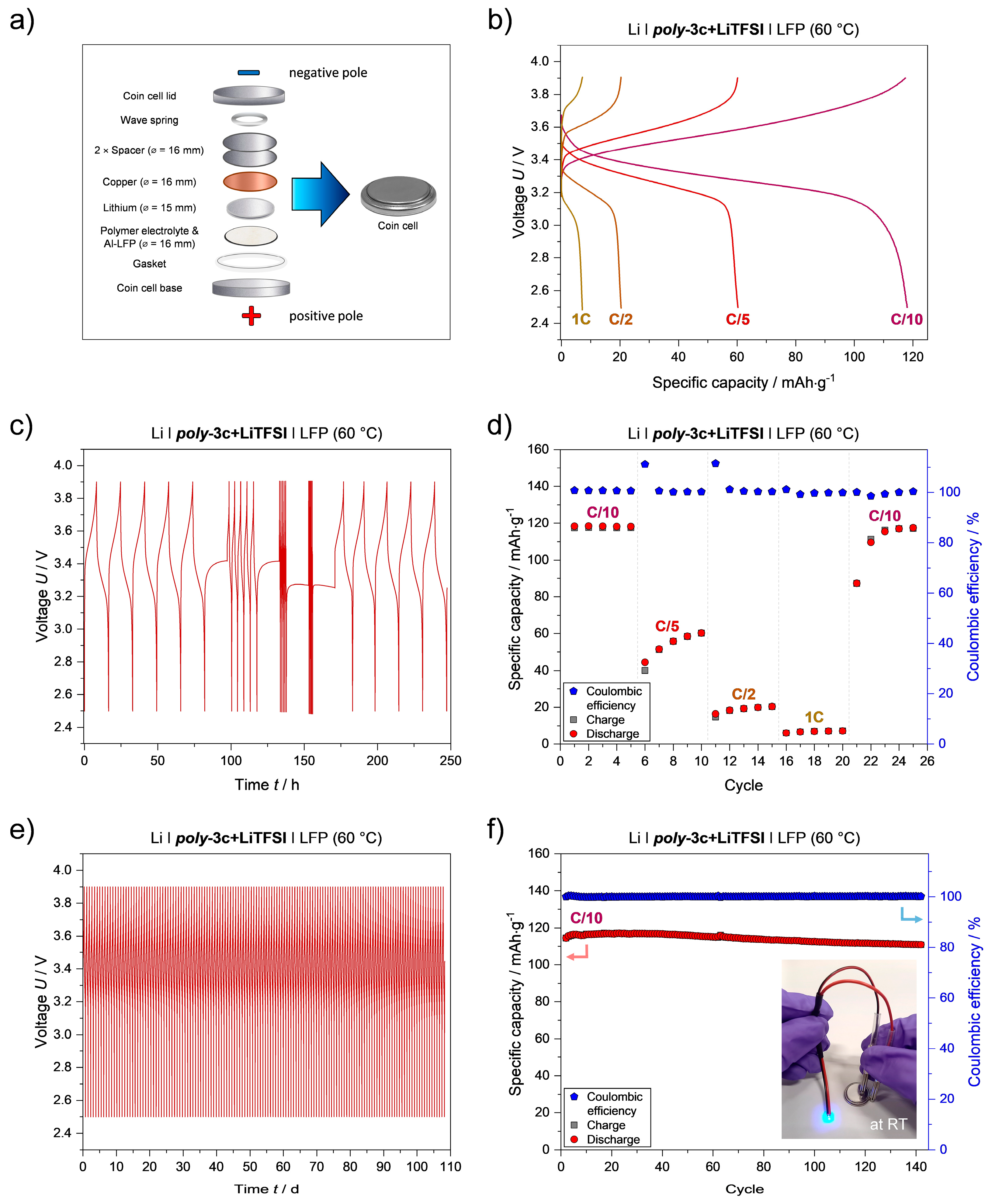
3.5. Cell Performance

Due to the highest absolute values in conductivity, lowest Tg, sufficient electrochemical stability window and mechanical strength electrolyte poly-3c+LiTFSI was favoured for cycling tests to evaluate the applicability of hbPG-based polymer electrolytes in ASSB cells. In general, the performance of an ASSB depends on the ion transport capacity of its SPE and on the interfacial contact between the electrolytes and the electrodes. The influence of cell temperature on the impedance and the enhancement of the Li+ diffusion at elevated temperature is well known [5,7,14,21].
Coin cells were assembled with coated SPE cathodes based on poly-3c+LiTFSI and a smaller lithium metal anode (see Figure 6a) to avoid short circuits. However, this proven setup results in lower capacity due to the reduced interfacial contact area (reduction of interfacial contact 12%) between the coated cathode and lithium. As a result, the full potential of the cells is not exploited. For the calculations of the maximum theoretical specific capacity of a cell, the reduced contact area was not taken into account.
The charge/discharge voltage curves at different C-rates of a Liǀpoly-3c+LiTFSIǀLFP cell at 60 °C, shown in Figure 6b,c, reveal the absence of flat charge/discharge plateaus. Normally, a flat charge/discharge plateau at ~3.4 V vs. Li/Li+ is typical for LFP [4]. This unusual curve shape indicates high polarization at the active material interfaces probably due to the slow diffusion coefficient of Li+ within the LFP cathode material and lack of interfacial contact [4]. Accordingly, the pronounced voltage hysteresis is due to the high overvoltages of the cell reaction.
Cycling capacities at different C-rates of a Liǀpoly-3c+LiTFSIǀLFP cell at 60 °C are shown in Figure 6d. At C/10, the specific capacity of the cell was 118 mAh g−1 (corresponding to ~74% of the theoretical capacity of LFP (~160 mAh g−1) [4]. The capacity values are lower than the theoretical specific capacity of LFP, because the cathode composition, manufacturing as well as electrode setup are not optimized. It is likely that the electrolyte has not penetrated deeply enough into the LFP cathode, even with liquid application. Thus, the interphase between the electrode and electrolyte is not sufficient to ensure proper ion transport.
As the C-rate increases, the specific capacity decreases strongly, which is probably due to a high charge concentration gradient in the electrolyte. After electrochemical stress, the cathode material recovered to a constant capacity level after a few cycles. At 1C, low capacities of around 7 mAh g−1 were achieved. The low specific capacities at high C-rates suggests that the electrolyte is not suitable for fast-charging. However, the Columbic efficiencies are close to 100%, except for the first cycle after the transition to a higher C-rate.
The observation that the Coulombic efficiencies are greater than 100% is attributed to the reconditioning time between the charge/discharge cycles and the open-circuit voltage (OCV) relaxation to a steady state value when current stops flowing [68]. This effect is associated with a change in starting conditions and the higher initial voltage illustrated by the state of charge between the respective cycles (see Figure 6c).
Remarkably, when the charge/discharge current returned from 1C to C/10, the specific capacity was reversibly restored after a few cycles to 117 mAh g−1, indicating that the poly-3c+LiTFSI-based SPE has both a good structural and a good electrochemical stability. As assumed above, a high C-rate leads to a high charge concentration gradient in the electrolyte. Despite an equilibrium period, this gradient effect may still be present in the first cycle after the current change, so that the cell reaches the charge cut-off potential relatively quickly. After a few cycles with a low C-rate of C/10, the concentration gradient relaxed again.
As shown in Supplementary Information—Figure S8, the Liǀpoly-3c+LiTFSIǀLFP cell provided lower capacity when the temperature was lowered to 30 °C, mainly due to the lower ionic conductivity of the SPE. Nevertheless, charge/discharge cycling at 30 °C is possible, but with restrictions in terms of the utilizable capacity. At high C-rates, the cut-off potential was quickly reached resulting in no capacity at 1C.
The specific capacities as a function of cycle number at constant C/10 rate of a Liǀpoly-3c+LiTFSIǀLFP cell at 60 °C are depicted in Figure 6f. At elevated temperatures of 60 °C the cell shows a stable cycling behaviour (see Figure 6e) with high Coulombic efficiencies. The good match between charge and discharge capacities implies that no side reactions such as decomposition of electrolyte take place, underlining the stable cycle behaviour. The cell delivered an initial specific discharge capacity of 115 mAh g−1. After 140 cycles, the specific discharge capacity was 111 mAh g−1. The specific capacity retention exceeded 97% of its initial capacity. The inset image in Figure 6f shows the functional demonstration of a charged Liǀpoly-3c+LiTFSIǀLFP coin cell at room temperature with a light-emitting diode (LED) as consumer.

4. Conclusions

For the first time, partially methylated and methacrylated hyperbranched polyglycerols (hbPG-MAx/OMey) with dissolved lithium conducting salt (LiTFSI) and different degree of crosslinking were investigated as solid polymer electrolytes (SPE) with regard to their suitability for the application in lithium metal batteries (LMBs). The ability to apply a solvent-free photopolymerization method using a release sheet greatly facilitated sample preparation and electrode coating on a laboratory scale. In dynamic mechanical analyses and impedance measurements, it was demonstrated that both mechanical strength and ionic conductivity could be varied by crosslinking via a tailored methacrylate substitution of the functional precursor macromolecule. In addition, it has been systematically shown that when the crosslink density of polymer electrolytes is reduced, the mechanical strength also decreases accordingly, while at the same time the conductivity increases due to the higher local structural chain motion. Therefore, both mechanical properties and conductivity are strongly interrelated and remain in counteraction to each other. The crosslinked and amorphous character of the hyperbranched scaffold influenced by lithium ion complexation and methacrylate crosslinking was also investigated. Differential scanning calorimetry, chronoamperometric and impedance measurements indicate that the hyperbranched polyether structure, in particular the polyglycerol-based backbone, interacts strongly with the lithium cations, as reflected by a strong increase in the glass transition temperature (Tg) after addition of LiTFSI to the polymer matrix and a low transfer number (tLi+). An impact of the degree of crosslinking on the pseudo-activation energy (Ep) could not be observed. For cycling performance tests in LMBs, the SPE poly-hbPG-MA0.05/OMe0.95+LiTFSI with the lowest methacrylate content was selected. This SPE showed the highest absolute conductivity (2.1 × 10⁻⁶ S cm−1 at 30 °C; 2.0 × 10⁻⁵ S cm−1 at 60 °C), the lowest Tg (from DSC: −39 °C), a sufficient electrochemical stability window (4.3 V vs. Li/Li+) and mechanical strength (1.6 ± 0.4 MPa at 25 °C). At low C-rates and elevated temperatures (60 °C), the LiǀSPEǀLFP cells were cycled with high Coulombic efficiency. However, when the C-rate was increased, the insufficient ionic conductivity led to a significant decrease in capacity.

Supplementary Materials

The following supporting information can be downloaded at: https://www.mdpi.com/article/10.3390/batteries9090431/s1. Figure S1. (a) FTIR spectra of hbPG-MAx/OMey+LiTFSI precursors. (b) FTIR spectra of UV cured poly-hbPG-MAx/OMey SPEs. Figure S2. DSC thermograms of hbPG-MAx/OMey+LiTFSI precursors with various degree of methylation and methacrylation as well as the DSC thermogram of the hbPG-OH0.02/OMe0.98+LiTFSI electrolyte. Figure S3. XRD diffractograms of poly-hbPG-MA0.05/OMe0.95+LiTFSI measured (a) on a glass sample holder and (b) on an Al target in an inert sample chamber. Figure S4. Section of a DMA measurement of poly-3c+LiTFSI with displayed loss factor (tan δ). Figure S5. Nyquist plots of poly-3c+LiTFSI at different temperatures. Figure S6. Temperature dependence of ionic conductivity as well as mechanical strength of hbPG based polymer electrolytes (Li:O = 1:20) with different degrees of methylation and methacrylation. Figure S7. Temperature dependence of ionic conductivity of hbPG based polymer electrolytes (Li:O = 1:20) with different degrees of methylation and methacrylation using Vogel-Tammann-Fulcher (VTF) fitting curves. Figure S8. (a) Voltage profiles of a Liǀpoly-3c+LiTFSIǀLFP cell at different C-rates at 30 °C. (b) Specific charge/discharge capacities of a Liǀpoly-3c+LiTFSIǀLFP cell at different C-rates at 30 °C. Table S1. Estimation of the shear modulus (G) based on the experimentally determined storage modulus (E′) at 25 °C assuming a Poisson’s ratio (µ) of 0.5 for each sample. Table S2. Parameters determined through experimental data fitting using Vogel-Tammann-Fulcher (VTF) model.

Author Contributions

N.N.: Conceptualization, Investigation, Visualization, Writing—original draft. G.A.: Supervision, Writing—review and editing. K.K.: Supervision, Funding acquisition, Resources. L.B.: Supervision, Writing—review and editing, Project administration. All authors have read and agreed to the published version of the manuscript.

Funding

This work is part of the project “MaLiFest” (11-76251-99-2/17 (ZN3402)), which is funded by the Lower Saxony Ministry of Science and Culture.

Data Availability Statement

The data presented in this study are available on request from the corresponding author.

Acknowledgments

The authors thank Matthias Ott for providing the PeelPLAS® release sheet. Further thanks to Iris Gottschalk for carrying out DSC and DMA measurements, Michael Gockeln for recording XRD diffractograms and Alexander Gräfenstein for the organization and production of LFP cathodes.

Conflicts of Interest

The authors declare that they have no known competing financial interests or personal relationships that could have appeared to influence the work reported in this paper.

References

  1. Schmuch, R.; Wagner, R.; Hörpel, G.; Placke, T.; Winter, M. Performance and cost of materials for lithium-based rechargeable automotive batteries. Nat. Energy 2018, 3, 267–278. [Google Scholar] [CrossRef]
  2. Armand, M.; Tarascon, J.-M. Building better batteries. Nature 2008, 451, 652–657. [Google Scholar] [CrossRef]
  3. Goodenough, J.B.; Kim, Y. Challenges for Rechargeable Li Batteries. Chem. Mater. 2010, 22, 587–603. [Google Scholar] [CrossRef]
  4. Korthauer, R. Handbuch Lithium-Ionen-Batterien, 1st ed.; Springer: Berlin/Heidelberg, Germany, 2013; ISBN 978-3-642-30653-2. [Google Scholar]
  5. Sun, C.; Liu, J.; Gong, Y.; Wilkinson, D.P.; Zhang, J. Recent advances in all-solid-state rechargeable lithium batteries. Nano Energy 2017, 33, 363–386. [Google Scholar] [CrossRef]
  6. Wagner, R.; Preschitschek, N.; Passerini, S.; Leker, J.; Winter, M. Current research trends and prospects among the various materials and designs used in lithium-based batteries. J. Appl. Electrochem. 2013, 43, 481–496. [Google Scholar] [CrossRef]
  7. Long, L.; Wang, S.; Xiao, M.; Meng, Y. Polymer electrolytes for lithium polymer batteries. J. Mater. Chem. A 2016, 4, 10038–10069. [Google Scholar] [CrossRef]
  8. Yue, L.; Ma, J.; Zhang, J.; Zhao, J.; Dong, S.; Liu, Z.; Cui, G.; Chen, L. All solid-state polymer electrolytes for high-performance lithium ion batteries. Energy Storage Mater. 2016, 5, 139–164. [Google Scholar] [CrossRef]
  9. Jiao, S.; Zheng, J.; Li, Q.; Li, X.; Engelhard, M.H.; Cao, R.; Zhang, J.-G.; Xu, W. Behavior of Lithium Metal Anodes under Various Capacity Utilization and High Current Density in Lithium Metal Batteries. Joule 2018, 2, 110–124. [Google Scholar] [CrossRef]
  10. Wang, Z.; Chen, S.; Huang, Z.; Wei, Z.; Shen, L.; Gu, H.; Xu, X.; Yao, X. High conductivity polymer electrolyte with comb-like structure via a solvent-free UV-cured method for large-area ambient all-solid-sate lithium batteries. J. Mater. 2019, 5, 195–203. [Google Scholar] [CrossRef]
  11. Zhang, H.; Armand, M. History of Solid Polymer Electrolyte-Based Solid-State Lithium Metal Batteries: A Personal Account. Isr. J. Chem. 2021, 61, 94–100. [Google Scholar] [CrossRef]
  12. Barteau, K.P.; Wolffs, M.; Lynd, N.A.; Fredrickson, G.H.; Kramer, E.J.; Hawker, C.J. Allyl Glycidyl Ether-Based Polymer Electrolytes for Room Temperature Lithium Batteries. Macromolecules 2013, 46, 8988–8994. [Google Scholar] [CrossRef]
  13. Lee, S.-I.; Schömer, M.; Peng, H.; Page, K.A.; Wilms, D.; Frey, H.; Soles, C.L.; Yoon, D.Y. Correlations between Ion Conductivity and Polymer Dynamics in Hyperbranched Poly(ethylene oxide) Electrolytes for Lithium-Ion Batteries. Chem. Mater. 2011, 23, 2685–2688. [Google Scholar] [CrossRef]
  14. Mindemark, J.; Lacey, M.J.; Bowden, T.; Brandell, D. Beyond PEO—Alternative host materials for Li + -conducting solid polymer electrolytes. Prog. Polym. Sci. 2018, 81, 114–143. [Google Scholar] [CrossRef]
  15. Li, J.; Cai, Y.; Wu, H.; Yu, Z.; Yan, X.; Zhang, Q.; Gao, T.Z.; Liu, K.; Jia, X.; Bao, Z. Polymers in Lithium-Ion and Lithium Metal Batteries. Adv. Energy Mater. 2021, 11, 2003239. [Google Scholar] [CrossRef]
  16. Zhao, Q.; Stalin, S.; Zhao, C.-Z.; Archer, L.A. Designing solid-state electrolytes for safe, energy-dense batteries. Nat. Rev. Mater. 2020, 5, 229–252. [Google Scholar] [CrossRef]
  17. Boaretto, N.; Garbayo, I.; Valiyaveettil-SobhanRaj, S.; Quintela, A.; Li, C.; Casas-Cabanas, M.; Aguesse, F. Lithium solid-state batteries: State-of-the-art and challenges for materials, interfaces and processing. J. Power Source 2021, 502, 229919. [Google Scholar] [CrossRef]
  18. Xue, Z.; He, D.; Xie, X. Poly(ethylene oxide)-based electrolytes for lithium-ion batteries. J. Mater. Chem. A 2015, 3, 19218–19253. [Google Scholar] [CrossRef]
  19. Klein, R.; Wurm, F.R. Aliphatic Polyethers: Classical Polymers for the 21st Century. Macromol. Rapid Commun. 2015, 36, 1147–1165. [Google Scholar] [CrossRef]
  20. Borodin, O.; Smith, G.D. Mechanism of Ion Transport in Amorphous Poly(ethylene oxide)/LiTFSI from Molecular Dynamics Simulations. Macromolecules 2006, 39, 1620–1629. [Google Scholar] [CrossRef]
  21. Aziz, S.B.; Woo, T.J.; Kadir, M.; Ahmed, H.M. A conceptual review on polymer electrolytes and ion transport models. J. Sci. Adv. Mater. Devices 2018, 3, 1–17. [Google Scholar] [CrossRef]
  22. Fan, L.-Z.; Maier, J. Composite effects in poly(ethylene oxide)–succinonitrile based all-solid electrolytes. Electrochem. Commun. 2006, 8, 1753–1756. [Google Scholar] [CrossRef]
  23. Jayathilaka, P.; Dissanayake, M.; Albinsson, I.; Mellander, B.-E. Effect of nano-porous Al2O3 on thermal, dielectric and transport properties of the (PEO)9LiTFSI polymer electrolyte system. Electrochim. Acta 2002, 47, 3257–3268. [Google Scholar] [CrossRef]
  24. Peters, F.; Langer, F.; Hillen, N.; Koschek, K.; Bardenhagen, I.; Schwenzel, J.; Busse, M. Correlation of Mechanical and Electrical Behavior of Polyethylene Oxide-Based Solid Electrolytes for All-Solid State Lithium-Ion Batteries. Batteries 2019, 5, 26. [Google Scholar] [CrossRef]
  25. Croce, F.; Persi, L.; Scrosati, B.; Serraino-Fiory, F.; Plichta, E.; Hendrickson, M. Role of the ceramic fillers in enhancing the transport properties of composite polymer electrolytes. Electrochim. Acta 2001, 46, 2457–2461. [Google Scholar] [CrossRef]
  26. Zhang, N.; He, J.; Han, W.; Wang, Y. Composite solid electrolyte PEO/SN/LiAlO2 for a solid-state lithium battery. J Mater. Sci. 2019, 54, 9603–9612. [Google Scholar] [CrossRef]
  27. Marzantowicz, M.; Dygas, J.R.; Krok, F.; Florjańczyk, Z.; Zygadło-Monikowska, E.; Lapienis, G. Ionic conductivity of electrolytes based on star-branched poly(ethylene oxide) with high concentration of lithium salts. Solid State Ion. 2011, 192, 137–142. [Google Scholar] [CrossRef]
  28. Nishimoto, A.; Watanabe, M.; Ikeda, Y.; Kohjiya, S. High ionic conductivity of new polymer electrolytes based on high molecular weight polyether comb polymers. Electrochim. Acta 1998, 43, 1177–1184. [Google Scholar] [CrossRef]
  29. Watanabe, M.; Endo, T.; Nishimoto, A.; Miura, K.; Yanagida, M. High ionic conductivity and electrode interface properties of polymer electrolytes based on high molecular weight branched polyether. J. Power Source 1999, 81–82, 786–789. [Google Scholar] [CrossRef]
  30. Nishimoto, A.; Agehara, K.; Furuya, N.; Watanabe, T.; Watanabe, M. High Ionic Conductivity of Polyether-Based Network Polymer Electrolytes with Hyperbranched Side Chains. Macromolecules 1999, 32, 1541–1548. [Google Scholar] [CrossRef]
  31. Watanabe, M.; Hirakimoto, T.; Mutoh, S.; Nishimoto, A. Polymer electrolytes derived from dendritic polyether macromonomers. Solid State Ion. 2002, 148, 399–404. [Google Scholar] [CrossRef]
  32. Kim, S.-C.; Oh, T.H.; Kim, D.W.; Lee, C.; Kang, Y. Ion-conducting hyperbranched PEG electrolytes derived from poly(glycidol). Macromol. Res. 2009, 17, 141–143. [Google Scholar] [CrossRef]
  33. Itoh, T. Effect of branching in base polymer on ionic conductivity in hyperbranched polymer electrolytes. Solid State Ion. 2002, 150, 337–345. [Google Scholar] [CrossRef]
  34. Gao, C.; Yan, D. Hyperbranched polymers: From synthesis to applications. Prog. Polym. Sci. 2004, 29, 183–275. [Google Scholar] [CrossRef]
  35. Hawker, C.J.; Chu, F.; Pomery, P.J.; Hill, D.J.T. Hyperbranched Poly(ethylene glycol)s: A New Class of Ion-Conducting Materials. Macromolecules 1996, 29, 3831–3838. [Google Scholar] [CrossRef]
  36. Xinling, W.; Jianjun, C.; Ling, H.; Xiaozhen, T. Synthesis and ionic conductivity of hyperbranched poly(glycidol). J. Polym. Sci. B Polym. Phys. 2001, 39, 2225–2230. [Google Scholar] [CrossRef]
  37. Xiaoying, S.; Xiaohui, Y.; Yunhang, L.; Xinling, W. Synthesis and characterization of a multiarm star polymer. J. Polym. Sci. A Polym. Chem. 2004, 42, 2356–2364. [Google Scholar] [CrossRef]
  38. Yang, X.; Sun, X.; Shao, J.; Liu, Y.; Wang, X. Ionic conductivity of multiarm star polymer/LiClO4 electrolytes. J. Polym. Sci. B Polym. Phys. 2004, 42, 4195–4198. [Google Scholar] [CrossRef]
  39. Sato, T. Ion-Conductive Polymer Electrolyte Composition of Polyglycidol. U.S. Patent 6,469,107 B1, 22 October 2002. [Google Scholar]
  40. Sato, T. Polymeric Compound, Polymer for Polyelectrolyte, and Composition for Ionically Conductive Polyelectrolyte. U.S. Patent 6,472,106 B1, 29 October 2002. [Google Scholar]
  41. Neumann, N.; Boskamp, L.; Hartwig, A.; Koschek, K. Synthesis and characterization of hyperbranched polyglycerols with various degree of methylation employing phase-transfer conditions. Polymer 2021, 229, 124002. [Google Scholar] [CrossRef]
  42. Itoh, T.; Gotoh, S.; Horii, S.; Hashimoto, S.; Uno, T.; Kubo, M.; Fujinami, T.; Yamamoto, O. Polymer electrolytes based on hyperbranched polymer with cross-linkable groups at the terminals. J. Power Source 2005, 146, 371–375. [Google Scholar] [CrossRef]
  43. Khurana, R.; Schaefer, J.L.; Archer, L.A.; Coates, G.W. Suppression of lithium dendrite growth using cross-linked polyethylene/poly(ethylene oxide) electrolytes: A new approach for practical lithium-metal polymer batteries. J. Am. Chem. Soc. 2014, 136, 7395–7402. [Google Scholar] [CrossRef]
  44. Fu, G.; Kyu, T. Effect of Side-Chain Branching on Enhancement of Ionic Conductivity and Capacity Retention of a Solid Copolymer Electrolyte Membrane. Langmuir 2017, 33, 13973–13981. [Google Scholar] [CrossRef] [PubMed]
  45. Neumann, N.; Thinius, S.; Abels, G.; Hartwig, A.; Koschek, K.; Boskamp, L. Multifunctional hyperbranched prepolymers with tailored degree of methylation and methacrylation. Polymer 2023, 276, 125886. [Google Scholar] [CrossRef]
  46. Evans, J.; Vincent, C.A.; Bruce, P.G. Electrochemical measurement of transference numbers in polymer electrolytes. Polymer 1987, 28, 2324–2328. [Google Scholar] [CrossRef]
  47. Scheller, J.; Brenner, T.; Ott, M.; Fladung, T.; Baur, P.J. Release properties of plasma polymeric coated polymer films and adhesive strength of transferred polyurethane coatings to fiber-reinforced thermosets. Adv. Manuf. Polym. Compos. Sci. 2022, 8, 11–21. [Google Scholar] [CrossRef]
  48. Sunder, A.; Mülhaupt, R.; Haag, R.; Frey, H. Hyperbranched Polyether Polyols: A Modular Approach to Complex Polymer Architectures. Adv. Mater. 2000, 12, 235–239. [Google Scholar] [CrossRef]
  49. Sunder, A.; Hanselmann, R.; Frey, H.; Mülhaupt, R. Controlled Synthesis of Hyperbranched Polyglycerols by Ring-Opening Multibranching Polymerization. Macromolecules 1999, 32, 4240–4246. [Google Scholar] [CrossRef]
  50. Frey, H.; Haag, R. Dendritic polyglycerol: A new versatile biocompatible material. Rev. Mol. Biotechnol. 2002, 90, 257–267. [Google Scholar] [CrossRef]
  51. Wilms, D.; Stiriba, S.-E.; Frey, H. Hyperbranched polyglycerols: From the controlled synthesis of biocompatible polyether polyols to multipurpose applications. Acc. Chem. Res. 2010, 43, 129–141. [Google Scholar] [CrossRef]
  52. Imholt, L.; Dörr, T.S.; Zhang, P.; Ibing, L.; Cekic-Laskovic, I.; Winter, M.; Brunklaus, G. Grafted polyrotaxanes as highly conductive electrolytes for lithium metal batteries. J. Power Source 2019, 409, 148–158. [Google Scholar] [CrossRef]
  53. Bardenhagen, I.; Soto, M.; Langer, F.; Koschek, K.; Schwenzel, J. Solid electrolyte based on 2-adamantanone for all-solid-state lithium-ion batteries. Ionics 2022, 28, 3615–3621. [Google Scholar] [CrossRef]
  54. Wen, S.J.; Richardson, T.J.; Ghantous, D.I.; Striebel, K.A.; Ross, P.N.; Cairns, E.J. FTIR characterization of PEO + LiN(CF3SO2)2 electrolytes. J. Electroanal. Chem. 1996, 408, 113–118. [Google Scholar] [CrossRef]
  55. Echeverri, M.; Kim, N.; Kyu, T. Ionic Conductivity in Relation to Ternary Phase Diagram of Poly(ethylene oxide), Succinonitrile, and Lithium Bis(trifluoromethane)sulfonimide Blends. Macromolecules 2012, 45, 6068–6077. [Google Scholar] [CrossRef]
  56. Fox, T.G.; Loshaek, S. Influence of molecular weight and degree of crosslinking on the specific volume and glass temperature of polymers. J. Polym. Sci. 1955, 15, 371–390. [Google Scholar] [CrossRef]
  57. Everaers, R.; Kremer, K. Test of the Foundations of Classical Rubber Elasticity. Macromolecules 1995, 28, 7291–7294. [Google Scholar] [CrossRef]
  58. Barai, P.; Higa, K.; Srinivasan, V. Lithium dendrite growth mechanisms in polymer electrolytes and prevention strategies. Phys. Chem. Chem. Phys. 2017, 19, 20493–20505. [Google Scholar] [CrossRef] [PubMed]
  59. Monroe, C.; Newman, J. The Impact of Elastic Deformation on Deposition Kinetics at Lithium/Polymer Interfaces. Electrochim. Acta 2005, 152, A396. [Google Scholar] [CrossRef]
  60. Deutsches Institut für Normung e. V. Kunststoffe—Bestimmung Dynamisch-Mechanischer Eigenschaften—Teil 1: Allgemeine Grundlagen; Beuth Verlag GmbH: Berlin, Germany, 2019. [Google Scholar]
  61. Elias, H.-G. Physikalische Strukturen und Eigenschaften, 6th ed.; Wiley-VCH: Weinheim, Germany, 2009; ISBN 3-527-29960-2. [Google Scholar]
  62. Bouchet, R.; Lascaud, S.; Rosso, M. An EIS Study of the Anode Li/PEO-LiTFSI of a Li Polymer Battery. Macromolecules 2003, 150, A1385. [Google Scholar] [CrossRef]
  63. Vadhva, P.; Hu, J.; Johnson, M.J.; Stocker, R.; Braglia, M.; Brett, D.J.L.; Rettie, A.J.E. Electrochemical Impedance Spectroscopy for All-Solid-State Batteries: Theory, Methods and Future Outlook. ChemElectroChem 2021, 8, 1930–1947. [Google Scholar] [CrossRef]
  64. Saeed, M.A.M.; Abdullah, O.G. Effect of High Ammonium Salt Concentration and Temperature on the Structure, Morphology, and Ionic Conductivity of Proton-Conductor Solid Polymer Electrolytes Based PVA. Membranes 2020, 10, 262. [Google Scholar] [CrossRef]
  65. Siekierski, M.; Bukat, M.; Ciosek, M.; Piszcz, M.; Mroczkowska-Szerszeń, M. Transference Number Determination in Poor-Dissociated Low Dielectric Constant Lithium and Protonic Electrolytes. Polymers 2021, 13, 895. [Google Scholar] [CrossRef]
  66. Tułodziecki, M.; Tarascon, J.-M.; Taberna, P.-L.; Guéry, C. Catalytic reduction of TFSI-containing ionic liquid in the presence of lithium cations. Electrochem. Commun. 2017, 77, 128–132. [Google Scholar] [CrossRef]
  67. Shin, W.; Manthiram, A. A Facile Potential Hold Method for Fostering an Inorganic Solid-Electrolyte Interphase for Anode-Free Lithium-Metal Batteries. Angew. Chem. Int. Ed. Engl. 2022, 61, e202115909. [Google Scholar] [CrossRef] [PubMed]
  68. Theuerkauf, D.; Swan, L. Characteristics of Open Circuit Voltage Relaxation in Lithium-Ion Batteries for the Purpose of State of Charge and State of Health Analysis. Batteries 2022, 8, 77. [Google Scholar] [CrossRef]
Figure 1. (a) The chemical synthetic route of crosslinked polymer species as well as solvation of Li+ conducting salt (LiTFSI) in the resulting SPE. (b) Schematic step-by-step illustration of electrode coating process.
Batteries 09 00431 g001
Figure 2. (a) DSC thermograms of hbPG-based polymer electrolytes with different degrees of methylation and methacrylation. (b) Glass transition temperature (Tg) of polymers species in dependence of the degree of methylation or methacrylation, before and after UV curing as well as lithium salt addition [41,45].
Batteries 09 00431 g002
Figure 3. (ac) Exemplary DMA measurements of selected poly-3a+LiTFSI, -3b+LiTFSI and -3c+LiTFSI samples and schematic experimental measuring setup (inset image). (d) Determined storage modulus E′ at 25 °C (red line) as well as determined Tg (blue line), both in dependence on the degree of methacrylation for the products poly-3a+LiTFSI, -3b+LiTFSI and -3c+LiTFSI. The Tg values were identified as the maximum of the loss modulus-temperature curves. The standard deviation was calculated from three measurements. Arrows indicates the correct axis for reading.
Batteries 09 00431 g003
Figure 4. Arrhenius plots of hbPG-based polymer electrolytes with different degrees of methylation and methacrylation with Li:O = 1:20.
Batteries 09 00431 g004
Figure 5. (a) Chronoamperometry of Liǀpoly-3c+LiTFSIǀLi cell with applied potential difference of 10 mV (60 °C). The inset shows the AC impedance spectra before and after polarization at 60 °C. (b) Linear sweep voltammogram of poly-3c+LiTFSI at 60 °C measured with a scan rate of 1 mV s−1. The negative scan is displayed in blue and the positive scan in red.
Batteries 09 00431 g005
Figure 6. (a) LFP-coated 2032-coin cell configuration. (b) In each case, the 5th charge/discharge voltage curve of a Liǀpoly-3c+LiTFSIǀLFP cell at different C-rates at 60 °C. (c) Voltage profiles of a Liǀpoly-3c+LiTFSIǀLFP cell at different C-rates at 60 °C. The C-rate is the same for discharge and charge process and change from C/10 to C/5, C/2, 1C each for five cycles and back to C/10. The potential window was set from 2.5 V to 3.9 V vs. Li/Li+. (d) Specific charge/discharge capacities and Coulombic efficiencies of a Liǀpoly-3c+LiTFSIǀLFP cell at different C-rates at 60 °C. (e) Voltage profiles of a Liǀpoly-3c+LiTFSIǀLFP cell at constant C/10 rate at 60 °C. (f) Specific charge/discharge capacities and Coulombic efficiencies of a Liǀpoly-3c+LiTFSIǀLFP cell at constant C/10 rate at 60 °C. Functional verification of a charged Liǀpoly-3c+LiTFSIǀLFP coin cell at room temperature using an LED (inset image).
Batteries 09 00431 g006
Table 1. Modified hbPG-based polymer electrolytes with individual degree of methylation (DM), degree of methacrylation substitution (DS), glass transition temperature (Tg), storage module (E′), ionic conductivity and transference number (tLi+).
No.Name aDM a
/%
DS a
/%
Tg DSC b
/°C
Tg DMA c
/°C
Ed
/MPa
Ionic Conductivity e
/S⋅cm−1 (30 °C) /S⋅cm−1 (60 °C)
tLi+ e
poly-3a+LiTFSIpoly-hbPG-MA0.26/OMe0.74+LiTFSI7426−18−7152 ± 283.2 × 10−99.1 × 10−80.19
poly-3b+LiTFSIpoly-hbPG-MA0.13/OMe0.87+LiTFSI8713−28−1922 ± 42.7 × 10−73.5 × 10−60.08
poly-3c+LiTFSIpoly-hbPG-MA0.05/OMe0.95+LiTFSI955−39−251.6 ± 0.42.1 × 10−62.0 × 10−50.07
3d+LiTFSIhbPG-OH0.02/OMe0.98+LiTFSI980−45--1.5 × 10−51.3 × 10−4-
a Composition determined via 1H NMR by integration of OH groups or CH3 from methacrylate groups compared with the CH3 group of the TMP core unit [41,45]; b Tg characterized by DSC; c Tg characterized by DMA, determined as the maximum of the loss modulus-temperature curves; d E′ was determined at 25 °C. The standard deviation was calculated from three measurements; e the average value was calculated from three measurements.
Disclaimer/Publisher’s Note: The statements, opinions and data contained in all publications are solely those of the individual author(s) and contributor(s) and not of MDPI and/or the editor(s). MDPI and/or the editor(s) disclaim responsibility for any injury to people or property resulting from any ideas, methods, instructions or products referred to in the content.

