Abstract
Germanium–cobalt–indium nanostructures were synthesized via cathodic electrodeposition from aqueous complex solutions of Ge (IV) and Co (II) with drop-like indium crystallization centers. This approach features simplicity, avoids heating and allows using cheaper GeO2 instead of pure Ge as starting material. Further, in this case, target nanostructures grow directly upon the substrate. Various analytical methods (scanning electron microscopy, transmission electron microscope and X-ray diffraction) were used for characterization of the nanostructures under study. The samples obtained consist of an array of globular particles of 200 to 800 nm, with nanowires in between. The globules, in turn, contain primary particles of 5 to 10 nm consisting of cobalt, germanium and oxygen. Nanowires consist of germanium and indium. The electrochemical properties of the above-mentioned nanostructures were assessed with cyclic voltammetry and galvanostatic cycling. The germanium–cobalt–indium nanostructures are characterized by a high specific capacity upon lithium insertion, which is approximately 1350 mAh/g at C/8, and a high Coulomb cycling efficiency in the first cycle (approximately 0.76). Germanium–cobalt–indium nanostructures show the ability to operate at high rates up to 16 C at a wide temperature range from +20 to −35 °C.
Keywords:
lithium-ion batteries; lithium insertion; germanium; cobalt; indium; anode materials; cyclability 1. Introduction
The importance of lithium-ion batteries in modern life cannot be overestimated and this is brilliantly confirmed by the award of the Nobel Prize in Chemistry in 2019 to J. Goodenough, M. S. Whittingham, and A. Yoshino precisely for the creation of these batteries. Despite the great progress made in their technology, improving their performance is still a key challenge [1]. In particular, many efforts are aimed toward development of new electrode materials with high insertion capacity, rate capability, and cyclability [2]. In the overwhelming majority of modern lithium-ion batteries, the negative electrodes (anodes) are made of carbon (graphitic) materials. Such materials have the ability to reversibly insert lithium and provide acceptable battery cycling, but their specific capacity being as low as 370 mAh/g leaves much to be desired. The materials possessing much higher theoretical specific capacity are well known, and among them, silicon has the maximal theoretical specific capacity of up to 4200 mAh/g [3]. Unfortunately, the use of silicon as a functional anode material has certain problems, and its commercialization is limited. Germanium is the nearest neighbor of silicon in the Periodic Table. Recently, rather interesting results on germanium-based anodes were reported (see, e.g., reviews [4,5]). Upon lithium insertion, germanium is able to form alloys Li15Ge4 and even Li22Ge5, which corresponds to a theoretical specific capacity of 1384, and 1624 mAh/g [6,7]. These quantities are 4 fold that of graphite. It is worth noting that both electronic conductivity and Li+ diffusivity of Ge are much higher, than that of Si [8]. Unfortunately, germanium, similar to other high-capacity materials, including silicon, suffers from huge inner tension and volume expansion at lithium insertion [4]. This volume expansion is accompanied by germanium cracking and disintegration, which results in growth of intergranular Ohmic resistance. Moreover, multiple periodical volume variations lead to corresponding periodical SEI destructions and recover with electrolyte expenditure. At least two strategies can be used for solving this problem: (i) passing to nanomaterials (including nanopowders, nanowires, thin films, and nanoporous bodies) and (ii) using multi-component systems (alloys, composites, etc.). The effective nanomaterials are germanium nanowires, made, e.g., via electrodeposition from aqueous GeO2 solution with drop-like indium crystallization centers [9]. Being an intermediate in the production of elemental germanium, GeO2 is much cheaper than germanium. It is worth noting that the electrochemical technique used in the present work allows growth of nanostructures directly on the electrode current collector, without binders or conductive additives. As for the multi-component system, the recent paper [10] deserves certain attention. Here, nanostructure composites Ge–Co-P with brutto-composition CoGe2P0.1 were manufactured via electrolysis of aqueous GeO2 electrolyte. Such composites demonstrated specific a capacity up to 855 mAh/g at 25 mA/g. The capacity fading in the long-term test with 400 mA/g amounting to 1.85 mAh per cycle or 0.27% per cycle.
Although some assumptions about the mechanism of the processes were put forward in [10], the role of individual components remained unclear. It is generally accepted that cobalt metal does not insert lithium [11]. At the same time, there are a lot of examples of the beneficial effect of cobalt in alloys, composites and various multi-component structures. In multi-phase systems [12,13,14,15,16,17,18], including core–shell structures [12,13,14], cobalt plays the role of support, which alleviates volume expansion and offers mechanical stability. Moreover, Co provides electrical conductivity in these cases. For instance, it was shown in [13] that Co shells on Si grains provide an approximately 44-fold deceleration of capacity fading. The authors of [15] demonstrated enhancement in specific capacity from 200 to 400 mAh/g when going from plain Ni3S2 to a composite of Ni3S2 with Co nanofibers. The article in [16] describes an interconnected Co-nanosheet array supported Si film showing excellent performances in terms of capacity and rate capability, and stable cycle ability. It is shown in [17] that cobalt in the Si/SiOx/Co composite plays the role of a mechanical buffer on the one hand, and of a conductive agent on the other hand. The electrode based on such a composite demonstrated a specific capacity up to 1602 mAh/g (of Si/SiOx) after 200 cycles at 2 A/g. In single-phase systems [19,20,21,22,23,24,25,26], including cobalt-based alloys [19,20,21,22], the alloys are destroyed at the first polarization with formation of inactive cobalt nanoparticles and a lithiated second component. It was noted in [10] that there are only three papers on the Ge–Co alloys in the literature [27,28,29] and all of them cannot be considered reliable. Indeed, the study in [27] describes composite CoGe2@C with a specific capacity very different to theoretical calculations, the study in [28] put forward an idea that Co is not an inactive component in the Ge−Co system because redox-transformation Co2+/Co3+ contributes some extra capacity, and the study in [29] reported a specific capacity 1535 mAh/g—an overestimation.
The present work is aimed to study the electrochemical behavior of Ge–Co–In electrodes manufactured via cathodic deposition similar to in [9]. In essence, this work is a continuation of studies [9,10].
2. Results
2.1. Morphological and Physical Studies
The morphology of the obtained sample is shown in Figure 1.
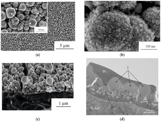
Figure 1.
SEM images of the surface (a,b) and cross-section (c) of the sample with different magnifications and TEM image of the cross-section (d). 1—spherical globular particles; 2—Ge nanowires.
One can see that the morphology of the sample differs from that of Ge nanowires [9] and composite CoGe2P0.1 [10]. The main structure unit in this case is globular particles with a characteristic diameter of 200 to 800 nm. Undoubtedly, these particles are secondary units consisting of primary particles of 5 nm, along with rare pieces of nanowires.
The investigation of the cross-section of the sample using TEM showed that spherical globular particles (1—Figure 1c) formed on top of the nanowires (2—Figure 1c), which are usually obtained by electrochemical deposition of Ge using In nanoparticles as crystallization centers of Ge [9].
Figure 2 shows the BF-STEM (Bright Field Scanning Transmission Electron Microscopy, JEOL, Tokyo, Japan) image of the sample and EDX maps corresponding to Ge, Co, In, as well as O and Cr. The signal from Cr (Figure 2f) appears in the EDX map due to the presence of the Cr sublayer, which was deposited for enhancing the adhesion of the main deposit to titanium foil (see the Section 4.1).
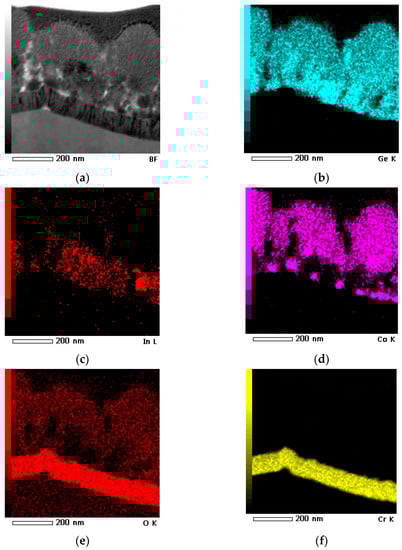
Figure 2.
BF-STEM image acquired from a sample side cleavage (a) along with EDX mapping of Ge (b), In (c), Co (d), O (e), and Cr (f).
A comparative qualitative analysis of the obtained maps of the elements distribution showed that the globular structures consist of cobalt, germanium and oxygen. In turn, the nanowires consist of germanium (Figure 2c) and contain both a dissolved indium in a small concentration (Figure 2d) and its inclusions, apparently related to In nanoparticles, which are located in nanowire vertices, which is typical for structures obtained by electrodeposition from aqueous solutions with indium crystallization centers [9].
Figure 3 presents the results of X-ray phase analysis, which enables drawing more or less certain conclusions about the phase composition of the material under study. On the X-ray pattern, along with intense peaks of titanium, there are low-intensity peaks at ~27.1°, 32.9°, 44.3°, 45.1°. Peaks at 27.1° and 45.1° can be attributed to the cubic modification of Ge (Card 04-0545), and that at 32.9° to the tetragonal modification of indium (70-2888). The peak at approximately 44.3° most likely belongs to the cubic modification of Co (89-7093). This sample was marked as a Ge–Co–In nanostructure.
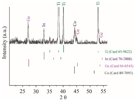
Figure 3.
XRD patterns of Ge–Co–In electrode.
2.2. Electrochemical Studies
Figure 4 shows the cyclic voltammograms (CVs) at Ge–Co–In for the first and the second cycles taken at a potential scan rate of 0.1 mV/s at temperatures of 20, 0, −20 and −35 °C.
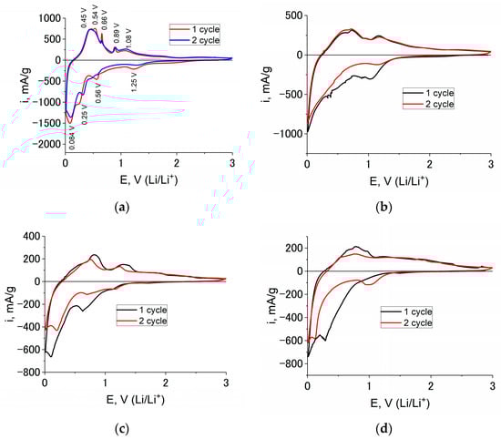
Figure 4.
CVs at Ge–Co–In sample for the first and the second cycles at a potential scan rate 0.1 mV/s and temperatures 20 (a), 0 (b), −20 (c), and −35 °C (d). The cycle numbers can be found in the figure.
CV registered at 20 °C (Figure 4a) reveals four clear cathodic peaks. The peak potential 1.32 V is related to the electrolyte reduction and SEI formation. The peaks at potentials 0.32 and 0.08 V are related to lithium insertion into germanium and indium with formation, correspondingly LixGe and LiyIn alloys. The cathodic peak at 0.56 V is related to lithium insertion into indium too. This fact is confirmed by CV, taken at indium electrode (Figure 5a). Temperature lowering results in negative shift of peak potentials (Figure 4b–d). For instance, the peak related to the electrolyte reduction lies at potentials 1.00, 0.65, and 0.30 V at the temperatures 0, −20 and −35 °C, respectively. Moreover, at the temperatures lower than 0 °C, the peaks corresponding to lithium insertion into germanium and indium combine in one poorly expressed peak.
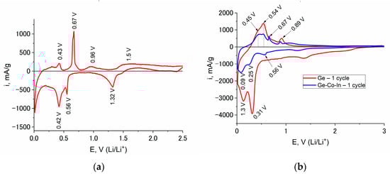
Figure 5.
CVs at In (a), Ge (b, red line) and Ge–Co–In (b, blue line) at a scan rate of 0.1 mV/s and a temperature of 20 °C. The cycle numbers can be found in the figure.
The anode part of the CV reflects the process of lithium extraction from LixGe and LiyIn. At a temperature of 20 °C, this process is described by two distinct peaks in the potential regions of 0.48 and 1.08 V, as well as two weak peaks in the potential regions of 0.66 and 0.89 V. The cathode peak at a potential of 0.56 V and the anode peak at a potential of 0.66 V refers to the insertion/extraction of lithium from LiyIn, which is also confirmed by the CV recorded in the interaction of indium with lithium (Figure 5a). As the temperature decreases, the anode current peaks shift in the positive direction. In addition, the peak height ratio changes, and at a temperature of −35 °C, some of the peaks disappear (Figure 4d).
Germanium-based anode materials are characterized by a large irreversible capacity in the first cycle [4], which is associated with the cracking of germanium upon lithium insertion and the formation of a new (fresh) germanium surface. The CV results showed that the irreversible capacity of Ge–Co–In in the first cycle turned out to be much less than that for germanium. Thus, the Coulomb efficiency of cycling of the first cycle for Ge and Ge–Co–In at a temperature of 20 °C was 0.26 and 0.70, respectively (Figure 5b). Lowering the temperature led to an increase in the Coulomb efficiency of the first cycle, so at temperatures of 0, −20 and −35 °C for Ge–Co–In it was 0.7, 079 and 0.8, respectively.
Comparison and analysis of the CV results (CVs at In, Ge and Ge–Co–In samples) suggest that the insertion of lithium into Ge–Co–In results in the formation of LixGe and LiyIn compounds (Figure 5b).
It is worth noting that CVs taken in the course of prolonged cycling at a scan rate of 0.2 mV/s shows the excellent stability of Ge–Co–In at reversible lithium insertion (Figure 6).
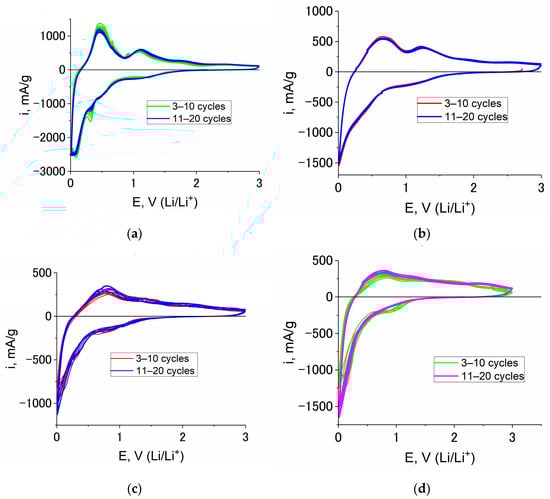
Figure 6.
CVs of Ge–Co–In sample at a scan rate of 0.2 mV/s and temperatures of 20 (a), 0 (b), −20 (c) and −35 °C (d). The cycle numbers can be found in the figure.
To confirm the rather good cyclability of Ge–Co–In, comparative CV tests were carried out with the electrodes made from Ge–In, Ge–Co and Ge–Co–In at room temperature. The results of multiple cycling are shown in Figure 7.
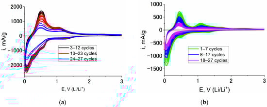
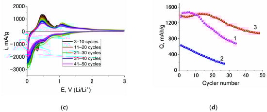
Figure 7.
Consecutive CVs taken at electrodes from Ge–In (a), Ge–Co (b), and Ge–Co–In (c); and capacity fading upon cycling of Ge–In (1), Ge–Co (2) and Ge–Co–In (3) (d).
Figure 7d earnestly shows advantages of Ge–Co–In in comparison with its counterparts. It must be especially stressed that all these CVs were measure without vinylene carbonate additives.
The results of galvanostatic studies of Ge–Co–In are shown in Figure 8. As can be seen from the curves, at all temperatures, the shape of the cathode curve in the first cycle slightly differs from the shape of the cathode curves in subsequent cycles, which is associated with the reduction in the electrolyte and the formation of SEI on the Ge–Co–In surface. The conclusion of the rather low irreversible capacity of the first cycle agrees with the above results of voltametric measurements. At the same time, at all temperatures, the cathodic capacity notably exceeds the anode capacity in the corresponding cycle. The Coulomb efficiency of cycling slightly depends on temperature and amounts to 0.68, 0.75, 0.76, and 0.78 at temperatures of 20, 0, −20, and −35 °C, respectively. The Ge–Co–In discharge capacity was 1360, 1206, 928 and 826 mAh/g at 20, 0, −20, and −35 °C, respectively (at 180 mA/g).
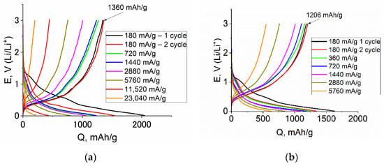
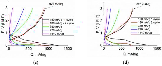
Figure 8.
Galvanostatic charge–discharge curves registered at Ge–Co–In at various current density and the temperatures of 20 (a), 0 (b), −20 (c), and −35 (d) °C.
The variations in the discharge capacity Q of Ge–Co–In during cycling with different current densities i at temperatures of 20, 0, −20 and −35 °C are shown in Figure 9. Figure 8a presents the initial data of discharge capacity, Figure 9b presents Q, i dependences in bi-logarithmic coordinates to determine the applicability of the Peuckert equation.
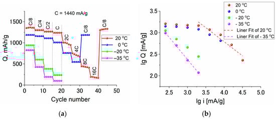
Figure 9.
The dependence of the discharge capacity of Ge–Co–In on current density in regular (a) and bi-logarithmic (b) coordinates. The current densities and temperatures are shown in the plots.
Figure 10 shows the temperature dependence of discharge capacity registered at various current densities. Here, this dependence is expressed in Arrhenius-kind coordinates, “logarithm of capacity vs. reciprocal absolute temperature”, which reflects the activation nature of the insertion process.
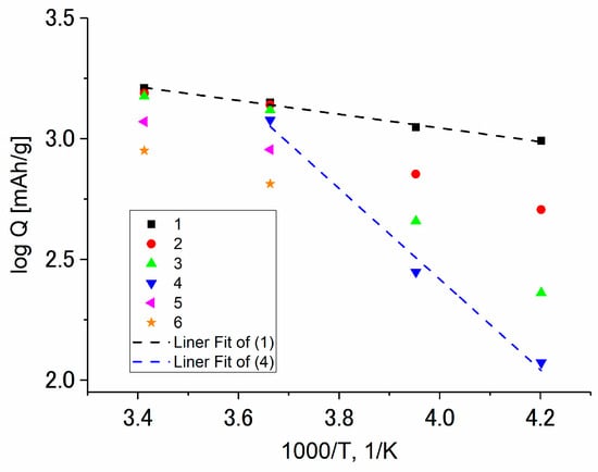
Figure 10.
The temperature dependence of the discharge capacity of Ge–Co–In measured at current densities (mA/g): 180 (1), 360 (2), 720 (3), 1440 (4), 2880 (5), and 5760 (6).
3. Discussion
According to EDX analysis, the sample under study contained 84% Ge, 7.6% In and 8.4% Co. The theoretical specific capacity of Ge for lithium insertion amounts to 1624 mAh/g, which corresponds to the stoichiometry of Ge5Li22 [30]. The theoretical specific capacity of indium is equal to 1010 mAh/g, which corresponds to the stoichiometry In3Li13 [31]. Therefore, the theoretical specific capacity of Ge–Co–In amounts to 1440 mAh/g (provided the cobalt metal does not insert lithium).
With due account for oxygen existence in the samples found by EDX, one cannot exclude the existence of some amount cobalt oxides (CoO or CoO2). It is known that such oxides reveal certain activity on lithium insertion (e.g., according the following process CoO + 2Li+ + 2e → Co + Li2O). It is worth noting that even if we suppose that all oxygen enters in CoO, the extra capacity will be 47 mAh/g (with due account for Co content 8.4%) or 3% of total theoretical capacity.
Figure 6 shows the outstanding cyclability of Ge–Co–In nanostructures. Indeed, the capacity fading at least for initial 20 cycles was under the limits of detection. It must be especially stressed that the results shown in Figure 6 were obtained without using additives of vinylene carbonate, which is known to increase the long-term cycling stability [32,33].
Figure 9b show that at room temperature, the measured discharge capacity is invariant at low current densities, and notable dependence on current reveals only for current densities higher than 2880 mA/g. In the range of higher current densities, the dependence formally obeys the Peukert equation Q = ki−α, with α close to 1, which is unusual. At the lowest temperature, such a dependence is shown at all current densities and α remains the same.
As can be seen from Figure 10, the temperature dependence of discharge capacity is usual. At low current densities, the slope of logQ,1/T dependence is vanishingly small and corresponds to formal activation energy ca. 5 kJ/mole. An increase in current density results in an increase in this quantity up to 38 kJ/mole.
4. Materials and Methods
4.1. Samples Preparation
A 50 µm thick Ti foil was used as the current collector substrate. The foil was pre-cleaned in H2O-H2O2-NH4OH solution (4:1:1) at a temperature of 80 °C for 15 min followed by washing in hot deionized water and drying in an air stream. A chromium layer of approximately 80 nm thickness was used to provide adhesion of the formed layer to the substrate. This layer was deposited by magnetron sputtering. The foil was cut into 2 × 3 cm pieces. Arrays of indium particles were formed using the electrochemical deposition method. Electrochemical deposition of indium was carried out in a two-electrode cell. The working electrode was a titanium-chrome (Ti-Cr) substrate with a chemically resistant varnish around the working area. A platinum plate was used as a counter electrode. The solution consisted of 0.015 M citric acid and 0.01 M indium chloride InCl3. Deposition was performed at room temperature in the galvanostatic mode at 2 mA/cm2 for 5 min. Deposition was performed at a solution temperature of 20 °C (maintained by a Termex VT-01 thermostat). The current density was set using an Autolab PGSTAT302N galvanostat/potentiostat. Currents are normalized to the geometric surface area of the electrode.
Ge–Co–In nanostructures were cathodically deposited in a conventional three-electrode electrochemical cell at a constant potential of −1.1 V (Ag/AgCl) for 10 min. The cell contained an auxiliary electrode made from platinum foil and a silver/silver chloride reference electrode. The cell was thermostated at 20 °C. To prepare the electrolyte for deposition, 1 part of solution A was mixed with 30 parts of solution B. The composition of solution A: 0.01 M CoSO4 and 0.1 M CH3COONa. The composition of solution B: 0.1 M GeO2, 0.1 M C4H6O4, and 0.5 M K2SO4.
Just after deposition, the nanostructures were rinsed with distilled water and dried with argon flow. The nanostructures were weighted by an analytical balance Metter Toledo XP 205 with an accuracy of 10 μg. The average load of nanostructures was 100 μg/cm2.
The formation of Ge–Co–In nanostructures is shown schematically in Figure 11.
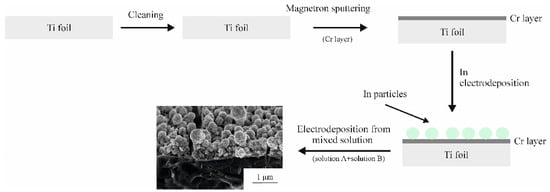
Figure 11.
Schematic representation of the formation of Ge–Co–In nanostructures.
4.2. Samples Physical Characterization of Ge–Co–In Nanostructures
The structural properties and elemental composition of the obtained samples were characterized by scanning electron microscopy (SEM) and energy-dispersive X-ray analysis (EDX) on an FEI Helios G4 CX Dual Beam scanning electron microscope (Thermo Fisher Scientific Inc., Waltham, MA, USA).
X-ray diffraction (XRD) pattern measurements were carried out in a Rigaku D/MAX 2200 diffractometer with a CuKα radiation.
For fine structure and elemental composition of nanostructure assessment, a JEOL JEM 2100 Plus transmission electron microscope (JEOL, Tokyo, Japan) was used. This microscope was supplied with a JEOL EX-24261M1G5T energy dispersive analyzer. The accelerating voltage was 200 kV, the electron beam current in the STEM mode was 1 nA. Preparation of the samples for TEM studies was carried out using a Helios G4CX FEI two-beam scanning electron microscope (Thermo Fisher Scientific Inc., Waltham, MA, USA). The Pt layer was used as a protective layer and for charge removal of the sample surface. Prior to TEM study, the sample was treated in plasma (75% argon and 25% oxygen) using a FISCHIONE model 1020 plasma cleaner.
4.3. Electrochemical Characterization
4.3.1. Electrochemical Setup
Sealed three-electrode cells were used for all electrochemical measurements. The cells were made of polytetrafluorethylene. To ensure the tightness of the cells, their housings and lids had flanges and were fastened with threaded studs. Each cell contained a working electrode (Ge–Co–In nanostructures on a titanium foil serving as a current collector), a counter electrode (lithium metal rolled onto a stainless steel current collector), and a reference electrode (lithium metal rolled also onto a stainless steel current collector). The visible surface area of the working electrode amounting to 1 cm2. The visible surface area of the auxiliary and reference ones was 1.5 cm2.
The working electrodes were preliminarily dried under vacuum at a temperature of 120 °C for 4 h. After drying, the electrodes in a sealed container were transferred into a glove box (Spektroskopicheskie Sistemy, Moscow, Russia) with dry oxygen-free argon (less than 1 ppm of O2 and H2O). The electrochemical cells were assembled and filled with electrolyte in this very glove box. A polypropylene separator (UFIM, Moscow, Russia) was impregnated by home-made electrolyte (1 M LiClO4 in a mixture of propylene carbonate and dimethoxyethane (7:3)). The original reagents for the electrolyte were qualified as Battery grade and were used without additional drying. The water content in the electrolyte was monitored by K. Fischer using a coulometric titrator (coulometer 917, Metrohm, Herisau, Switzerland). The amount of water did not exceed 20 ppm.
Low-temperature electrochemical measurements were carried out using a KTX-65-165 climatic chamber (Smolenskoye SKTB SPU, Smolensk, Russia) combined with a P-20X potentiostat (ELINS STC JSC, Moscow, Russia). The temperature accuracy was 0.1 °C. Prior to measurements, the electrochemical cells were placed in the climatic chamber and kept at a given temperature for 2 h.
4.3.2. Electrochemical Measurements
Cyclic voltammetry curves (the dependence of current on potential) of the test samples were recorded using a P-20X potentiostat (ELINS STC JSC, Moscow, Russia). The potential scan rates were 0.1 mV/s for the initial two cycles and 0.2 mV/s for the subsequent cycles.
Chropotentiometry (galvanostatic method) was used to study the dependence of the working electrode potential on the transmitted charge. Galvanostatic charge–discharge curves were recorded using an AZRIVK-0.05A-5 V multichannel computer-aided cycler (JSC Buster, Moscow, Russia). The charge current corresponded to the cathodic polarization (lithium insertion) and the discharge current corresponded to the anode polarization (lithium extraction). In all cases, the charge current was equal to the discharge current. The charge was carried out to an end potential of 10 mV, and the discharge was carried out to a potential of 3000 mV. The current densities ranged from 180 to 23,040 mA/g. The specific current and specific capacitances were calculated relative the weight of Ge–Co–In. The current equal to 1440 mA/g corresponded to a 1 C rate.
5. Conclusions
Recently, germanium is considered as a rather promising active material for a negative electrode (anode) of lithium-ion batteries. Indeed, Ge can form alloys with lithium up to composition Li22Ge5, which corresponds to an insertion capacity as high as 1624 mAh/g. Unfortunately, lithium insertion into germanium is accompanied by notable volume expansion and corresponding growth of internal stresses, which results in destruction (cracking and pulverization) of the Ge-based electrode. This failure can be avoided by using nanostructures as well as multi-component systems.
In the present work, the germanium–cobalt–indium nanostructures were synthesized by cathodic deposition from aqueous complex solutions of Ge (IV) and Co (II) upon titanium sheets with indium nanoseeds for the first time. The obtained nanostructures do not contain any binders as well as conducting additives. These nanostructures can be synthesized at supports with various geometry and composition. It is important that the nanostructures described in the present work can be manufactured by roll-to-roll technology on an industrial scale. The nanostructures have globular morphology and contain secondary spherical globules with a diameter from 200 to 800 nm consisting of primary particles of 5 to 10 nm. In the space between the globules, some nanowires are located. The globules contain Co, Ge and O, whereas the nanowires consist of Ge and In. In the course of galvanostatic cycling, the electrode based on Ge–Co–In nanostructures demonstrates a rather high specific capacity for lithium insertion, amounting to 1350 mAh/g at the rate C/8 and room temperature, as well as a high Coulomb efficiency of 76% even in the first cycle. The Ge–Co–In nanostructure can be charged and discharged at 16 C (23 A/g) at a temperature range from +20 to −35 °C. The salient feature of the above described nanostructures is their very good cyclability; capacity fading does not exceed 0.04% per cycle (without the use of electrolyte additives such as vinylene carbonate). Thus, the synthesized Ge–Co–In nanostructures can be considered as a high-capacity stable anode material for the negative electrodes of lithium-ion batteries.
Author Contributions
S.A.G., writing of original draft and supervision; I.M.G., methodology, investigation, and writing of original draft; I.K.M., investigation; T.L.K., conceptualization, writing of original draft, and methodology; E.V.K., investigation and visualization; A.M.S., conceptualization, supervision; M.V.P., investigation; L.S.V., investigation; S.A.N., investigation. All authors have read and agreed to the published version of the manuscript.
Funding
This work was supported by a grant from Russian Science Foundation No 20-79-10312, https://rscf.ru/en/project/20-79-10312/ (accessed on 20 July 2020).
Data Availability Statement
Not applicable.
Conflicts of Interest
The authors declare no conflict of interest.
References
- Kim, T.; Song, W.; Son, D.-Y.; Ono, L.K.; Qi, Y. Lithium-ion batteries: Outlook on present, future, and hybridized technologies. J. Mater. Chem. A 2019, 7, 2942–2964. [Google Scholar]
- Mahmud, S.; Rahman, M.; Kamruzzaman, M.; Ali, M.O.; Emon, M.S.A.; Khatun, H.; Ali, M.R. Recent advances in lithium-ion battery materials for improved electrochemical performance: A review. Results Eng. 2022, 15, 100472. [Google Scholar]
- Mukanova, A.; Jetybayeva, A.; Myung, S.-T.; Kim, S.-S.; Bakenov, Z. A mini-review on the development of Si-based thin film anodes for Li-ion batteries. Mater. Today Energy 2018, 9, 49–66. [Google Scholar]
- Wu, S.; Han, C.; Iocozzia, J.; Lu, M.; Ge, R.; Xu, R.; Lin, Z. Germanium-Based Nanomaterials for Rechargeable Batteries. Angew. Chem. Int. Ed. 2016, 55, 7898–7923. [Google Scholar]
- Hu, Z.L.; Zhang, S.; Zhang, C.J.; Cui, G.L. High performance germanium-based anode materials. Coordin. Chem. Rev. 2016, 326, 34–85. [Google Scholar]
- Sangster, J.; Pelton, A.D. The Ge-Li (germanium-lithium) system. J. Phase Equil. 1997, 18, 289–294. [Google Scholar]
- Morris, A.J.; Grey, C.P.; Pickard, C.J. Thermodynamically stable lithium silicides and germanides from density functional theory calculations. Phys. Rev. B 2014, 90, 054111. [Google Scholar]
- Graetz, J.; Ahn, C.C.; Yazami, R.; Fultz, B. Nanocrystalline and thin film germanium electrodes with high lithium capacity and high-rate capabilities. J. Electrochem. Soc. 2004, 151, A698–A702. [Google Scholar]
- Gavrilin, I.M.; Kudryashova, Y.O.; Kuz’mina, A.A.; Kulova, T.L.; Skundin, A.M.; Emets, V.V.; Volkov, R.L.; Dronov, A.A.; Borgardt, N.I.; Gavrilov, S.A. High-rate and low-temperature performance of germanium nanowires anode for lithium-ion batteries. J. Electroanalyt. Chem. 2021, 888, 115209. [Google Scholar]
- Kulova, T.L.; Skundin, A.M.; Gavrilin, I.M.; Kudryashova, Y.O.; Martynova, I.K.; Novikova, S.A. Binder-Free Ge-Co-P Anode Material for Lithium-Ion and Sodium-Ion Batteries. Batteries 2022, 8, 89. [Google Scholar]
- Nzereogu, P.U.; Omah, A.D.; Ezema, F.I.; Iwuoha, E.I.; Nwanya, A.C. Anode materials for lithium-ion batteries: A review. Appl. Surf. Sci. Adv. 2022, 9, 100233. [Google Scholar] [CrossRef]
- Chen, X.; Huang, Y.; Zhang, K. Cobalt nanofibers coated with layered nickel silicate coaxial core-shell composites as excellent anode materials for lithium-ion batteries. J. Colloid Interface Sci. 2018, 513, 788–796. [Google Scholar] [CrossRef]
- Cetinkaya, T.; Uysal, M.; Guler, M.O.; Akbulut, H. Developing lithium-ion battery silicon/cobalt core-shell electrodes for enhanced electrochemical properties. Int. J. Hydrog. Energy 2014, 39, 21405–21413. [Google Scholar] [CrossRef]
- Chen, X.; Huang, Y.; Han, X.; Zhang, K. Synthesis of cobalt nanofibers and nickel sulfide nanosheets hierarchical core-shell composites for anode materials of lithium-ion batteries. Electrochim. Acta 2018, 284, 418–426. [Google Scholar] [CrossRef]
- Chen, X.; Huang, Y.; Zhang, K.; Zhang, W. Cobalt fibers anchored with tin disulfide nanosheets as high-performance anode materials for lithium-ion batteries. J. Colloid Interface Sci. 2017, 506, 291–299. [Google Scholar] [CrossRef] [PubMed]
- Huang, X.H.; Wu, J.B.; Cao, Y.Q.; Zhang, P.; Lin, Y.; Guo, R.Q. Cobalt nanosheet arrays supported silicon film as anode materials for lithium-ion batteries. Electrochim. Acta 2016, 203, 213–220. [Google Scholar] [CrossRef]
- Suh, S.; Choi, H.; Eom, K.S.; Kim, H.-J. Enhancing the electrochemical properties of a Si anode by introducing cobalt metal as a conductive buffer for lithium-ion batteries. J. Alloys Compd. 2020, 827, 154102. [Google Scholar] [CrossRef]
- Park, H.; Kim, K.; Jeong, K.; Kang, J.S.; Choe, H.-H.; Thirumalraj, B.; Sung, Y.-E.; Han, H.N.; Kim, J.-H.; Dunand, D.C.; et al. Integrated porous cobalt oxide/cobalt anode with micro- and nano-pores for lithium-ion battery. Appl. Surf. Sci. 2020, 525, 146592. [Google Scholar] [CrossRef]
- Zhang, Z.; Yan, X.; Li, C.; Song, H.; Mao, C.; Peng, H.; Li, G. Nitrogen-doped carbon sphere encapsulating antimony-cobalt antimony binary nanoseeds as promising anode material for high performance lithium-ion battery. J. Alloys Compd. 2020, 821, 153500. [Google Scholar] [CrossRef]
- Zhu, J.; Sun, T.; Chen, J.; Shi, W.; Zhang, X.; Lou, X.; Mhaisalkar, S.; Hng, H.H.; Boey, F.; Ma, J.; et al. Controlled Synthesis of Sb Nanostructures and Their Conversion to CoSb3 Nanoparticle Chains for Li-Ion Battery Electrodes. Chem. Mater. 2010, 22, 5333–5339. [Google Scholar] [CrossRef]
- Park, M.-G.; Song, J.H.; Sohn, J.-S.; Lee, C.K.; Park, C.-M. Co–Sb intermetallic compounds and their disproportionated nanocomposites as high-performance anodes for rechargeable Li-ion batteries. J. Mater. Chem. A 2014, 2, 11391–11399. [Google Scholar] [CrossRef]
- Xie, J.; Zhao, X.B.; Cao, G.S.; Zhao, M.J.; Su, S.F. Solvothermal synthesis and electrochemical performances of nanosized CoSb3 as anode materials for Li-ion batteries. J. Power Sources 2005, 140, 350–354. [Google Scholar] [CrossRef]
- Fei, H.; Liu, X.; Li, Z. Hollow Cobalt Coordination Polymer Microspheres: A Promising Anode Material for Lithium-ion Batteries with High Performance. Chem. Eng. J. 2015, 281, 453–458. [Google Scholar] [CrossRef]
- Ashraf, S.; Mehek, R.; Iqbal, N.; Noor, T.; Ali, G.; Wahab, A.; Qayyum, A.A.; Ahmad, A. ZIF 67 derived Co–Sn composites with N-doped nanoporous carbon as anode material for Li-ion batteries. Mater. Chem. Phys. 2021, 270, 124824. [Google Scholar] [CrossRef]
- Wang, D.; Zhou, J.; Li, J.; Jiang, X.; Wang, Y.; Gao, F. Cobalt-boron nanoparticles anchored on graphene as anode of lithium-ion batteries. Chem. Eng. J. 2019, 360, 271–279. [Google Scholar] [CrossRef]
- Skoda, D.; Kazda, T.; Munster, L.; Hanulikova, B.; Styskalik, A.; Eloy, P.; Debecker, D.P.; Vilcakova, J.; Cech, O.; Simonikova, L.; et al. Microwave-assisted synthesis of platelet-like cobalt metal-organic framework, its transformation to porous layered cobalt-carbon nanocomposite discs and their utilization as anode materials in sodium-ion batteries. J. Energy Storage 2020, 27, 101113. [Google Scholar] [CrossRef]
- Zhao, W.; Chen, J.; Lei, Y.; Du, N.; Yang, D. A novel three-dimensional architecture of Co–Ge nanowires towards high-rate lithium and sodium storage. J. Alloys Compd. 2020, 815, 152281. [Google Scholar] [CrossRef]
- Kim, D.-H.; Park, C.M. Co–Ge compounds and their electrochemical performance as high-performance Li-ion battery anodes. Mater. Today Energy 2020, 18, 100530. [Google Scholar] [CrossRef]
- Jing, Y.-Q.; Qu, J.; Jia, X.-Q.; Zhai, X.-Z.; Chang, W.; Zeng, M.-J.; Li, X.; Yu, Z.-Z. Constructing tunable core-shell Co5Ge3@Co nanoparticles on reduced graphene oxide by an interfacial bonding promoted Kirkendall effect for high lithium storage performances. Chem. Eng. J. 2021, 408, 127266. [Google Scholar] [CrossRef]
- Dadd, A.T.; Hubberstey, P. Solubilities of silicon and of germanium in liquid lithium. Lithium–germanium partial phase diagram. J. Chem. Soc. Faraday Trans. 1 F 1981, 77, 1865. [Google Scholar] [CrossRef]
- Zhou, X.; Zhang, F.; Liu, S.; Du, Y.; Jin, B. Phase equilibria and thermodynamic investigation of the In–Li system. Calphad 2020, 70, 101779. [Google Scholar] [CrossRef]
- Kennedy, T.; Mullane, E.; Geaney, H.; Osiak, M.; O’Dwyer, C.; Ryan, K.M. High-Performance Germanium Nanowire-Based Lithium-Ion Battery Anodes Extending over 1000 Cycles Through in Situ Formation of a Continuous Porous Network. Nano Lett. 2014, 14, 716–723. [Google Scholar] [CrossRef] [PubMed]
- Kulova, T.L.; Gavrilin, I.M.; Kudryashova, Y.O.; Skundin, A.M.; Gavrilov, S.A. Cyclability enhancement and decreasing the irreversible capacity of anodes based on germanium nanowires for lithium-ion batteries. Mendeleev Commun. 2021, 31, 842–843. [Google Scholar] [CrossRef]
Disclaimer/Publisher’s Note: The statements, opinions and data contained in all publications are solely those of the individual author(s) and contributor(s) and not of MDPI and/or the editor(s). MDPI and/or the editor(s) disclaim responsibility for any injury to people or property resulting from any ideas, methods, instructions or products referred to in the content. |
© 2023 by the authors. Licensee MDPI, Basel, Switzerland. This article is an open access article distributed under the terms and conditions of the Creative Commons Attribution (CC BY) license (https://creativecommons.org/licenses/by/4.0/).