Article

An Investigation into Sustainable Solutions: Utilizing Hydrated Lime Derived from Oyster Shells as an Eco-Friendly Alternative for Semiconductor Wastewater Treatment

Center for Bioresources Recycling, Institute for Advanced Engineering, Yongin 11780, Republic of Korea
*
Author to whom correspondence should be addressed.
Recycling 2024, 9(4), 61; https://doi.org/10.3390/recycling9040061
Submission received: 20 June 2024 / Revised: 10 July 2024 / Accepted: 24 July 2024 / Published: 26 July 2024

Abstract

:
Due to its acidic nature and high fluoride concentration, hydrated lime (Ca(OH)2) is commonly used for neutralization and fluoride control in semiconductor wastewater treatment. This study investigated the efficacy of treating high fluoride-containing wastewater using hydrated lime derived from oyster shells as an alternative to limestone. Overall, the characteristics of removing pollutants in acidic wastewater using shell-based hydrated lime showed similar patterns to hydrated lime from limestone. The treatment efficiency was 50% or less under theoretical Ca/F molar ratio (=0.5) conditions for the formation of fluorite (CaF2), while the fluorine removal rate reached 99% under somewhat higher Ca/F conditions due to the influence of ionic components in the wastewater. Interestingly, chloride content did not increase even in the initial reaction stages, in contrast to our concerns about oyster shells generally containing salt to a certain extent due to their growth in seawater; instead, the chloride concentration decreased over time, similar to nitrate (NO3). In controlling fluoride in wastewater, surpassing the theoretical Ca/F molar ratio, particularly considering the presence of other anionic species such as SO4²− and PO4³, the optimal Ca/F ratio for fluoride removal was found to be 1.59. This value is approximately 16% lower than the calculated value (Ca/F = 1.85) when accounting for other anions. X-ray diffraction results confirmed the presence of CaSO4, Ca3(PO4)2, and CaF2 in the precipitate recovered after the reaction, indicating the effective removal of ionic contaminants. This observation suggests that oyster shell-derived hydrated lime could serve as a viable calcium resource for treating acidic wastewater and represents a potential alternative to traditional limestone-based methods.

1. Introduction

Fluoride (F) is essential for bone health but prolonged exposure to elevated concentrations can result in various health issues including fluorosis, osteomalacia, dental fluorosis, and neurological damage to bones and skeletons [1,2]. The World Health Organization (WHO) warns that even with concentrations of fluorine specifically in the range of 1–2 mg/L over an extended period may lead to fluorosis. In Korea, the Drinking Water Management Act regulates fluoride as an inorganic substance harmful to human health, establishing a drinking water quality standard of 1.5 mg/L. This emphasizes the importance of monitoring and controlling fluoride levels in drinking water to protect public health.
Fluoride in water primarily originates from the dissolution of F-bearing minerals such as fluorite, phosphorite, and mica, as well as from natural sources such as volcanoes and hot springs. Without artificial contamination, the fluoride concentration increases mainly due to water-rock interactions. However, the rapid expansion of the electronics industry has introduced a new environmental challenge, emerging as a notable source of high fluoride pollution discharged through wastewater [3].
Semiconductor production, known for its complexity, involves processes such as deposition, photoresist coating, lithography, etching, doping, and washing [4]. These processes utilize various acidic chemicals, such as hydrofluoric acid (HF), sulfuric acid (H2SO4), nitric acid (HNO3), and phosphoric acid (H3PO4), leading to the generation of acidic wastewater containing harmful substances [5,6]. Wastewater from this sector accounts for approximately 19.3% of daily industrial wastewater generation in Korea (approximately 177,937 m3/day), imposing a significant environmental burden [6]. This highlights the need for heightened awareness and management to address the potential environmental impacts of fluoride discharge from electronic manufacturing processes.
Various technologies, including adsorption [7,8], ion exchange [9], precipitation [10,11,12], reverse osmosis, and electrodialysis [13,14], are actively being explored for treating acidic wastewater containing fluoride. Given that semiconductor wastewater typically has a low pH, methods such as adsorption or ion exchange, despite facing pH challenges, are widely adopted due to their cost-effectiveness and the absence of the need for precipitation. The precipitation method involves removing calcium ions from sources such as Ca(OH)2, CaCl2, and CaCO3 and forming fluorite (CaF2) through a chemical reaction, as follows:
Ca(OH)2 + 2F → CaF2 + 2H2O
CaCl2 + 2F + 2H+ → CaF2 + 2H+ + 2Cl
CaCO3 + 2F + 2H+ → CaF2 + 2H+ + CO32−
However, the fluorite formed in the process cannot be entirely removed from the water due to its solubility (0.016 g/L at 20 °C). Furthermore, compounds that are insoluble in water, resulting from reactions with calcium-based compounds, combine with various anions present in water to form insoluble compounds [15]. These anions include Cl, PO4³, NO3, SO4², etc. Lu and Liu [16] confirmed that the presence of phosphorus in water leads to the formation of a precipitate in the form of hydroxyapatite (Ca10(PO4)6(OH)2) when the pH increases, hindering fluoride removal. Consequently, it is more common to inject an excess of the required Ca content for fluoride treatment through precipitation than the theoretically required amount.
To replace Ca-based sources as adsorption materials, extensive studies are being conducted to identify calcium-replacement materials from various waste resources. Notably, oyster shells have garnered attention as an alternative material to limestone owing to their high Ca content and potential for waste recycling. Despite being primarily studied as an adsorbent for acid gas in the literature [17,18,19,20], limited research has explored its suitability for fluoride treatment. As environmental concerns grow, there is an increasing demand for research on shell materialization. However, few studies have investigated the application of shells in treating acidic wastewater, especially in the semiconductor industry. This emphasizes the need for studies investigating the use of shells as wastewater treatment agents. Research from Lee et al. [21] and Ha et al. [22] suggested that oyster shells possess a greater specific surface area and calcium content than limestone after calcination due to their rough surface properties. Additionally, unlike limestone, shells contain elevated levels of Na, Cl, P, and S, which persist even after calcination [22].
This study conducted a comparative experiment to assess the reactivity of shell-based calcium compounds for fluoride treatment in comparison to traditional limestone-based hydrated lime. Importantly, the experiment utilized industrial wastewater generated from a semiconductor process rather than simulated fluorine-containing wastewater. This approach allows for the observation of the effects on various ion components present in wastewater. This study revealed that the reactivity of oyster shell-based hydrated lime is very similar to that of limestone-based material. Specifically, chloride concentrations did not increase over time, despite oyster shells having relatively higher chloride content compared to limestones. However, it was confirmed that a high Ca/F molar ratio of 2.0 or higher is necessary for both limestone and shell-based materials for effective fluoride treatment because of the presence of high levels of anionic chemical species in wastewater. These findings indicate the potential industrial use of oyster shells, an abandoned waste material, as an alternative to existing limestone.

2. Results and Discussion

2.1. Chemical Compositions of Semiconductor Wastewater

Table 1 presents the results of the water quality analysis for the semiconductor wastewater obtained in this study. The wastewater was of a highly acidic nature with a pH of approximately 1.84. Notably, the fluoride ion content measured at 3286 ppm was accompanied by elevated concentrations of Cl, NO3, PO43−, and SO42−. The concentration of SO42− exceeded 15,000 ppm, which was notably greater than that of the other anions. These distinctive characteristics, including the high levels of hydrofluoric acid (HF) and the prevalence of strong acids such as hydrochloric acid (HCl), nitric acid (HNO3), sulfuric acid (H2SO4), and phosphoric acid (H3PO4), appear to align with the semiconductor manufacturing process, particularly in the etching and cleaning stages [5,6].

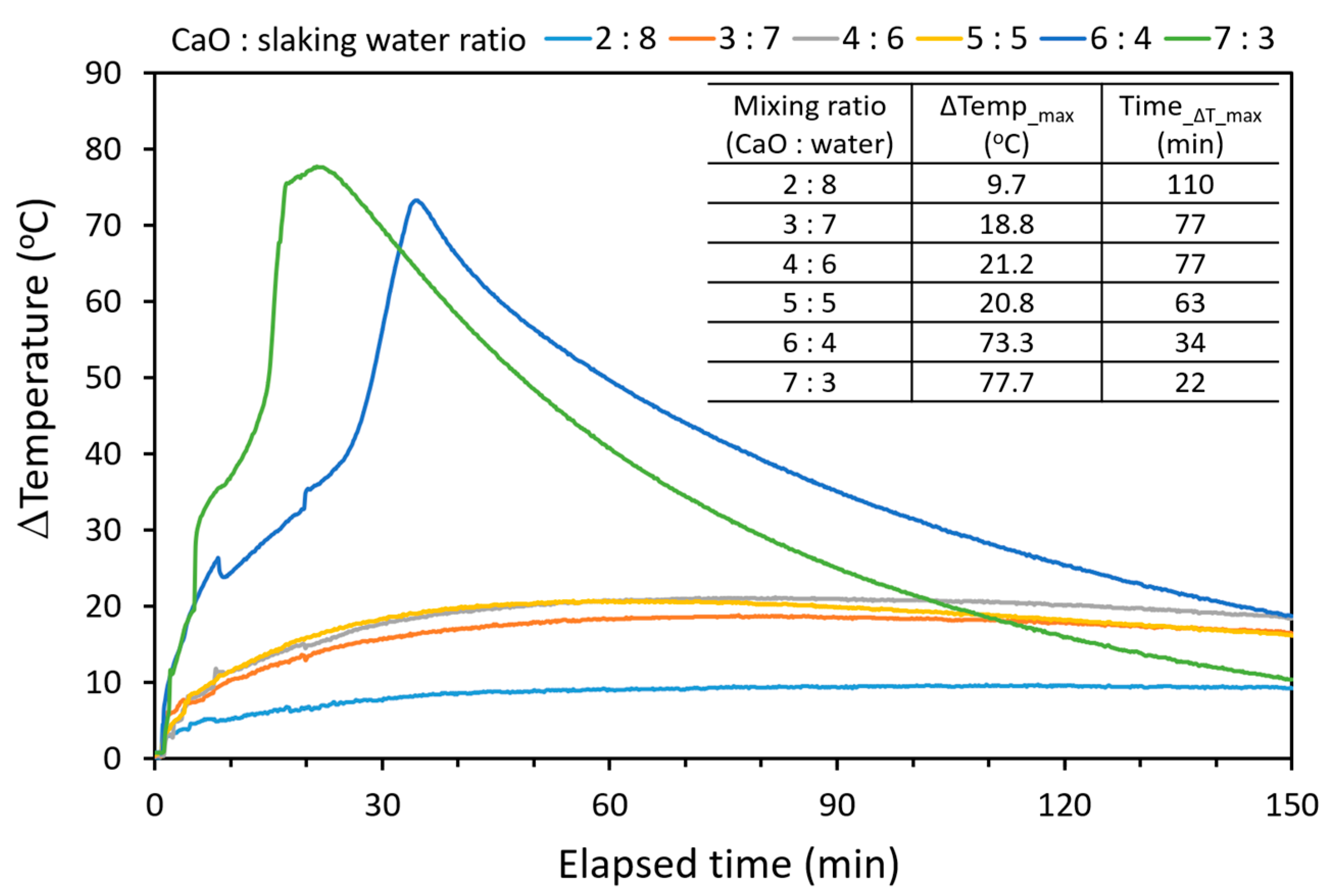
2.2. Hydration of CaO from Calcined Oyster Shell and Limestone

Hydrated lime is produced by a hydration reaction of quicklime (CaO), wherein the exothermic reaction is produced as depicted in Equation (4).
CaO(s) + H2O(l) ↔ Ca(OH)2(l) + Heat (ΔH298K = −104 KJ/mol)
Figure 1 illustrates the variations in heat during the hydration of oyster shell-based CaO and compares it with that of CaO derived from limestone. Unlike limestone, oyster shells exhibit relatively low heat at the same solid-to-liquid ratio. If the mixing ratio of CaO to slaked water is 2:8, the temperature of the slaked water can reach approximately 100 °C, according to the theoretical heat of hydration shown in Equation (4). Factors influencing the hydration rate include the CaO purity, the initial temperature of the slaking water, and the CaO-to-slaking water ratio. As depicted in Figure 1, the maximum temperature, which serves as an indirect indicator of hydration rates, is highly variable and depends not only on the quality of the CaO but also on the initial slaking water temperature. Even when calcined oyster shells with CaO contents exceeding 97% were utilized, the exothermic patterns were notably lower, with temperature differences between the reactants and the atmosphere less than 10 °C. In investigations varying the mixing conditions of CaO to slaking water (2:8, 3:7, 4:6, 5:5, 6:4, and 7:3), hydration accelerated when the ratio of CaO exceeded 1.0 for the slaking water (6:4 and 7:3). Under these two conditions, the maximum temperatures reached 73.3 °C and 77.7 °C, respectively, which were significantly higher than the relatively lower mixing ratios. Moreover, there was a noticeable difference in the hydration rates calculated by the time required to reach the highest temperature.
In contrast to the pattern of limestone, hydration using oyster shells typically requires increasing the temperature to enhance the reactivity or using relatively hot initial slaking water at approximately 80 °C [22]. However, these results indicate that controlling the mixing ratio of CaO to slaking water can improve the hydration rate, irrespective of the initial slaking water temperature. These findings suggest a method to enhance reactivity in the production of hydrated lime based on CaO prepared from oyster shells.

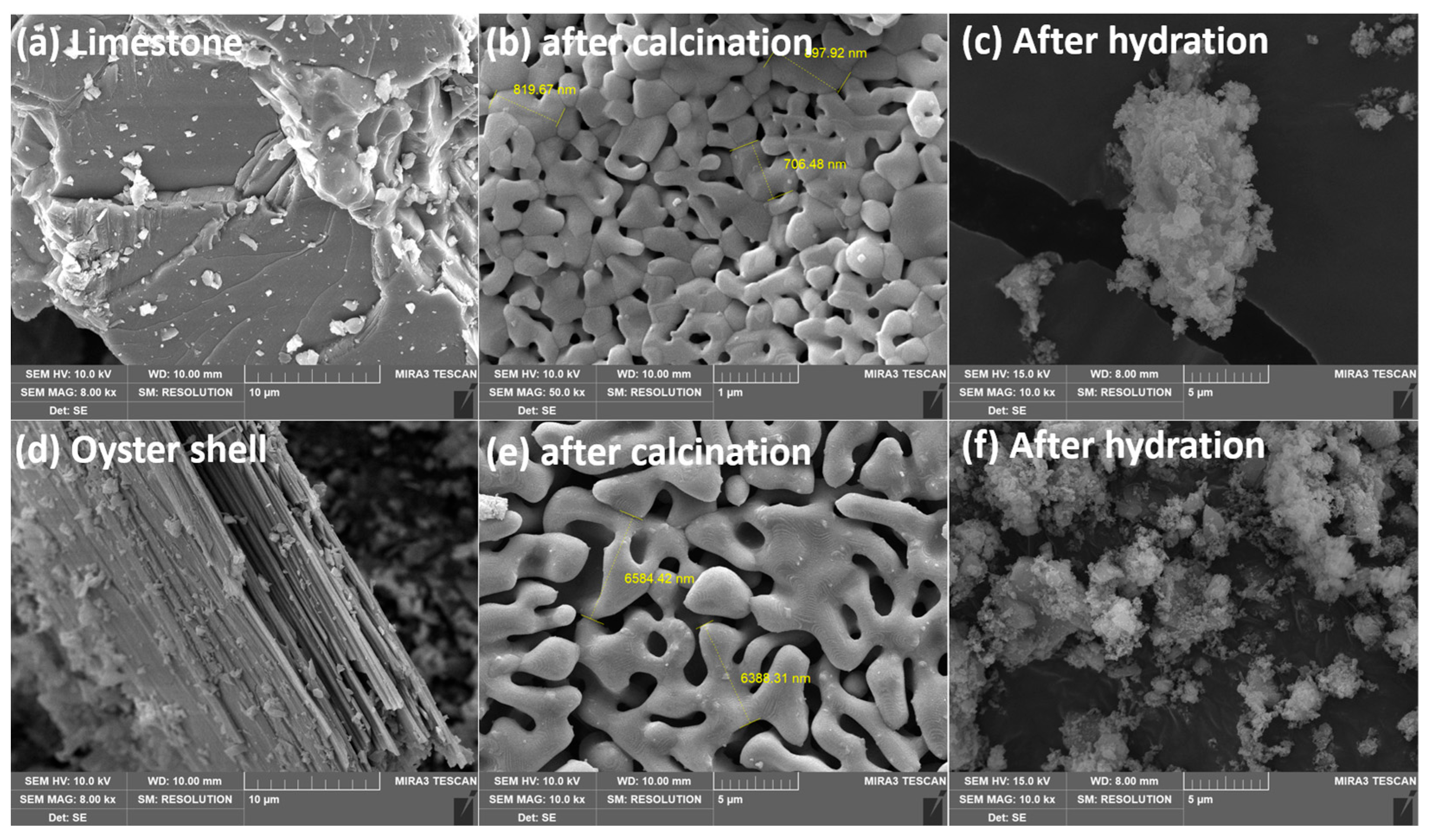
2.3. SEM Images for Quick and Hydrated Lime

Previous studies [21,22] have indicated that oyster shells and limestone exhibit distinct surface morphologies. Limestone typically possesses a dense structure, whereas oyster shells display a layered, stacked structure. However, after calcination, both materials exhibit increased porosity due to CO2 degassing, and particle size is further known to increase during sintering at higher temperatures [21]. Figure 2 shows SEM photographs of oyster shells and limestone after calcination at 900 °C, revealing no clear differences between the two samples. Notably, the oyster shell, with its plate-like structure, results in relatively larger particles after calcination compared to limestone due to faster sintering under identical conditions. Specifically, the size of calcined oyster shell particles is approximately seven times larger than that of limestone (Figure 2b,e). However, both samples of hydrated lime derived from oyster shells and limestone consist of aggregated fine particles, with no significant differences observed in their appearance.

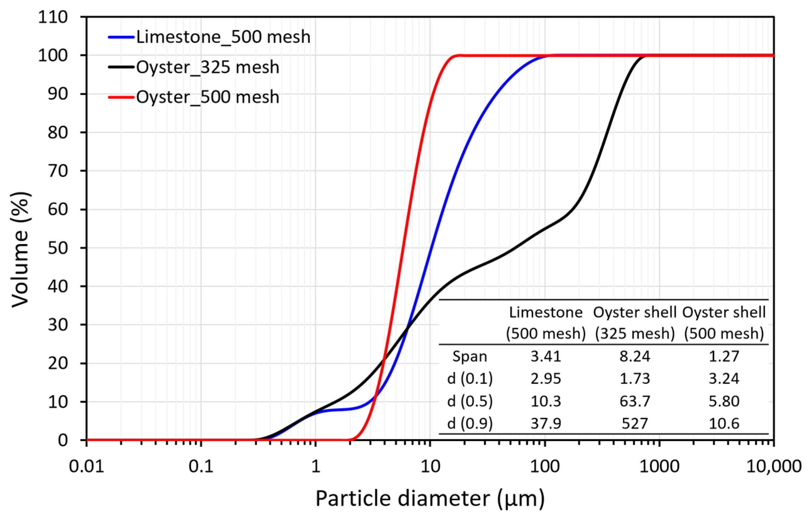
2.4. Particle Distribution of Hydrated Lime

When hydrated lime is prepared through a hydration reaction, it forms very small particles. However, these particles easily bond to each other, existing in the form of larger aggregates. Typically, the average ξ-potential of Ca(OH)2 dispersed in water is known to be approximately 34 mV [23]. Consequently, diluted hydrated lime is expected to maintain dispersibility through electrostatic repulsion, as proposed by the Derjaguin–Landau–Verwey–Overbeek (DLVO) theory. Given that the concentration of Ca(OH)2 in this study was greater than 20 wt%, some particles were prone to aggregation. Moreover, colloidal particle forms are known to grow irreversibly into new crystals on the crystal surface [24,25,26]. Unfortunately, these newly formed crystals do not completely restore their colloidal properties during heteroepitaxial rearrangement.
Figure 3 compares the particle size distribution of the hydrated lime produced from oyster shells and limestone. The limestone-based hydrated lime used in this study is a commercial product with a 500-mesh (=25 μm) passed sample. The value of d(0.5), the 50% size distribution cutoff point, is approximately 10 μm, and the span value is 3.4, indicating no significant deviation in the particle size. Even though the limestone-based hydrated lime passed through the 500 mesh, only approximately 80% of the total particles were less than 25 μm, and some large particles up to 130 μm in size were also observed.
On the other hand, the particle size distribution patterns of the hydrated lime produced from oyster shells showed high variance depending on the particle size. Two main peaks were observed for the sample that passed through the 325 mesh. The d(0.5) of the sample passing through the 325 mesh was approximately 63 μm, but the d(0.9) was approximately 530 μm, characterized by a wide particle size distribution. However, in the case of a sample that passed through the 500 mesh, the particle size showed a relatively homogeneous distribution after sieving with 500-mesh screens. It is characterized by a finer particle size (d(0.5) = 5.8 μm, d(0.9) = 10.6 μm) than limestone. Nevertheless, considering that Ca(OH)2 particles prepared by hydration agglomerate with time [27], the large particles of limestone-based hydrated lime that passed through the 500 mesh in this study also seem to reflect the above characteristics. However, these shell samples, like limestone, are expected to grow particles via entanglement with each other.

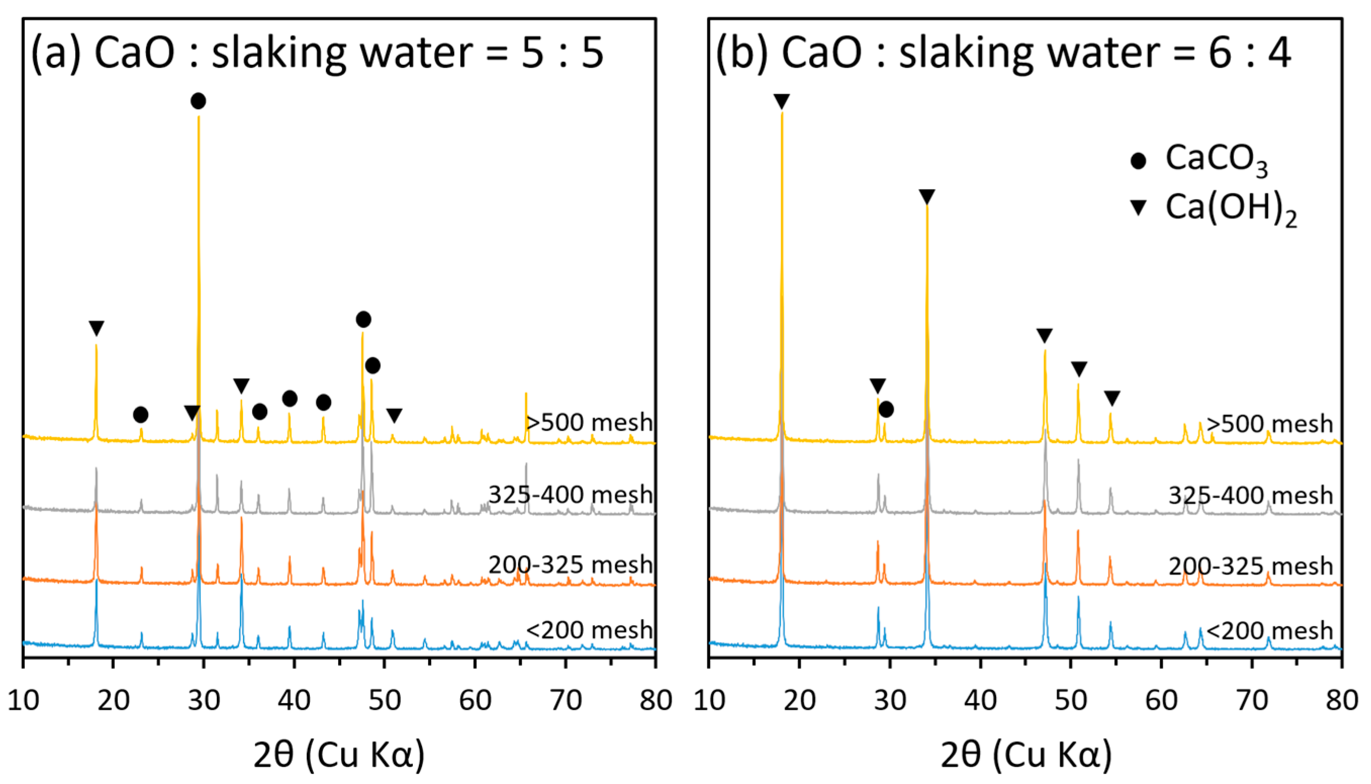
2.5. Mineralogical Properties of Hydrated Lime Derived from Oyster Shells

Calcium oxide undergoes a transformation into Ca(OH)2 through hydration. In contrast, the CaCO3 remaining in the calcined oyster shell and limestone, which was not completely calcined, retained its mineral phase and rarely dissolved in slaking water. To elucidate the mineral phase transition of the prepared hydrated lime, Figure 4 displays the XRD peak patterns after hydration. Throughout the hydration process, Ca(OH)2 is dominantly observed, indicating a substantial transformation. However, CaCO3 still existed after hydration, irrespective of the particle size, with the peak intensity varying based on the hydration conditions. Specifically, a higher CaO/slaking water ratio (1:1) results in a more pronounced conversion of CaO to Ca(OH)2. Conversely, when CaO and the hydration solution are mixed at a ratio of 5:5, CaCO3 becomes the primary peak across all particle sizes. These findings are corroborated by the table inserted in Figure 1. Examining the heat of hydration at a CaO–slaking water ratio of 1:1 revealed a minimal value at 20.8 °C. However, with an increased proportion of CaO, the hydration heat increases to 70 °C or higher within a relatively short reaction time. On the other hand, when considering limestone, the classification characteristics of CaCO3/Ca(OH)2 become more evident, particularly with respect to particle size.
Figure 5 presents a comparison of the XRD results for hydrated lime sieved through a 200 mesh and prepared at a CaO–slaking water ratio of 6:4 for both oyster shell and limestone. In the case of the oyster shell, CaCO3 was observed alongside Ca(OH)2, consistent with Figure 4b, but Ca(OH)2 dominated. In contrast, hydrated lime derived from limestone undergoes a phase transition to Ca(OH)2 through hydration. Furthermore, there is a distinct difference in mineral composition depending on particle size. At particle sizes coarser than the 200 mesh, Ca(OH)2 was the major mineral peak, resembling the pattern observed in oyster shells. However, even when Ca(OH)2 is present after sieving through tthe 200 mesh, CaCO3 is identified as the major mineral phase. Consequently, it is inferred that the persistence of the CaCO3 peak in the hydration reactant results from an incomplete phase transition from CaCO3 to Ca(OH)2 during calcination, influenced by the remaining CaCO3. Considering that the limestone used in this study has a particle size of approximately 5 mm, it is suggested that CO2 escapes, and the phase transition to CaO during calcination may not fully progress. As a result, it is hypothesized that larger particles undergo sintering externally, where heat transfer is effectively conducted, but complete phase transition does not occur internally.

2.6. Fluoride Removal of Hydrated Lime

2.6.1. Comparative Results for Oyster Shell and Limestone

Figure 6 illustrates the variations in the concentration of anionic species over reaction time, considering the particle size and Ca/F molar ratio of the prepared hydrated lime. Upon the injection of hydrated lime, there is a rapid decrease in the concentration of dissolved ions in wastewater. When comparing particle sizes passing through the 500 mesh from oyster shell and limestone, no significant differences were observed in the reduction patterns of dissolved ions. All the ions were effectively removed at a Ca/F molar ratio of 0.5, which is consistent with the theoretical value for fluorine removal. However, for particles coarser than the 325 mesh, the relative concentration (C/Co) of dissolved ions highly depended on the Ca/F ratio, particularly for F, SO4², and PO4³. The reduction in ionic concentration was noticeable and appeared to reach a plateau to some extent. Even when Ca(OH)2 derived from oyster shells passed through the 325 mesh and the 500 mesh was compared, and a higher concentration of F was observed compared to that of the fine particles, particle size emerged as a key factor influencing the reactivity of hydrated lime in acidic wastewater.
Table 2 summarizes the removal efficiencies for each dissolved ion with a 10 min reaction time. With a Ca/F ratio of 0.5, only approximately 40% of the fluorine was removed, and there was no further increase in removal efficiency even with extended reaction times. Additionally, injecting hydrated lime at twice the theoretical value (Ca/F = 1.0) did not significantly improve the F removal efficiency, which decreased by approximately 50%. Conversely, hydrated lime passed through the 500 mesh displayed high efficiency, exceeding 95% even under Ca/F = 0.5. While a higher dosage of hydrated lime may be required due to the levels of reactive ions (SO4², PO4³, Cl, and NO3) in the acidic wastewater used in this study, particle size appears to have a more pronounced impact than the Ca/F molar ratio on fluoride removal efficiency.
Similar patterns were observed for SO4², NO3, and PO4³, with slight variations in degree. A clear reduction in relative concentration was observed at the beginning of the reaction, and the removal efficiency approached 100% at a Ca/F ratio of 2.5. However, the level of Cl- increased under low Ca/F conditions, increasing by approximately 10% in the first 5 min of the reaction at Ca/F = 0.5. This increase is attributed to the influence of salt remaining in the shell, as shells are known to contain a certain amount of Na+ and Cl even after washing, as indicated by Ha et al. [22]. Despite using washed oyster shells followed by calcination in this study, it appears that some Cl remained in the hydrated lime. At a Ca/F ratio of 2.5, a decreasing pattern was observed from the beginning, suggesting that under high Ca/F conditions, Ca(OH)2 precipitation induced by excess Ca(OH)2 injection predominates over the effect of Cl from the shell.

2.6.2. pH Variations of Hydrated Lime Produced from Oyster Shells and Limestones

As hydrated lime reacts with acidic wastewater, the pH of the wastewater gradually increases due to the formation of mineral phases such as CaF2, CaSO4, Ca3(PO4)2, CaCl2, and Ca(NO3)2 by the neutralization of acidic wastewater. Figure 7 compares the observed pH values during the injection of hydrated lime made from two different materials into the semiconductor wastewater used in this study. The Ca/F molar ratio was calculated based on the content and injection volume of the hydrated lime. Changes in the pH of the hydrated lime made from shell and limestone are clearly observed according to the Ca/F molar ratio, and the differences between these two materials are also similar. Even under a Ca/F molar ratio of 1.2, the pH was as low as approximately 2.0, reaching near-neutral levels in the wastewater only when the Ca/F molar ratio was close to 1.6. However, the variations in pH are significant, indicating that the pH gradually recovers with the injection of hydrated lime. Beyond a given Ca/F molar ratio of 1.6, the changes in pH correspond quickly to the changes in the injected hydrated lime with minimal deviation. This recovery characteristic of pH aptly explains the removal efficiency of low ionic components at the previously low Ca/F ratio. Additionally, a similar pH buffering effect was observed for the hydrated limes made from limestone and oyster shells. The pH changes in shell-based hydrated lime from these two sources show similar results in terms of pH buffering for acid wastewater, indicating industrial applicability.

2.6.3. Effects of the Ca/F Molar Ratio

To ascertain the appropriate injection amount of hydrated lime for treating acidic wastewater, we confirmed the removal rate of dissolved ions by adjusting the injection amount, as shown in Figure 8. The removal rates of dissolved ions for the two types of hydrated lime were very similar. Although there were differences in the degree of removal for each dissolved ion, the oyster shell-based hydrated lime exhibited a somewhat higher removal rate of dissolved ions at the same Ca/F molar ratio.
While both oyster shell and limestone-based hydrated lime used in this experiment passed through a 500 mesh (26 μm) screen in the same manner, the particle size of the shell-based hydrated lime consisted of finer particles, approximately three times greater than that of limestone (Figure 3). This finer particle size likely contributed to the higher removal rate of dissolved ions in shell-based hydrated lime, reflecting the effect of the particle size of the prepared hydrated lime. Despite these differences, the reaction characteristics of both materials were very similar.
The fluorine removal rate was confirmed at a Ca/F ratio of 1.6, surpassing the theoretical value (Ca/F ratio = 0.5). Additionally, the removal rate of PO4³ increased rapidly at that point (Ca/F = 1.6). When comparing the removal rates of dissolved ions while increasing the Ca/F ratio, F and PO4³ showed removal rates close to 100% under a Ca/F ratio of 1.6. Conversely, SO4² exhibited a somewhat lower efficiency with a removal rate of approximately 80%, while NO3 and Cl showed only approximately 30% to 40% efficiency, even at a Ca/F molar ratio of 3.0. In acidic wastewater, various ions, including fluorine, exist, and these ions can be removed through the following reactions (Equations (5)–(9))
Ca(OH)2 + 2HF → CaF2 + H2O
Ca(OH)2 + 2HCl → CaCl2 + 2H2O
3Ca(OH)2 + 2H3PO4 → Ca3(PO4)2 + 6H2O
Ca(OH)2 + 2HNO3 → Ca(NO3)2 + 2H2O
Ca(OH)2 + H2SO4 → CaSO4 + 2H2O
Due to the presence of various ions in acidic wastewater, the amount of hydrated lime required for wastewater treatment was found to be excessive. Considering the concentration of ionic species in the wastewater, the Ca/F molar ratio necessary for removing these ionic components based on Equations (5)–(9) is calculated as 1.85. Despite a calculated error rate of approximately 16% compared to the measured value (Ca/F = 1.59), our results effectively demonstrate that the amount of hydrated lime injected must be considered in conjunction with the content of dissolved ions for treating acidic wastewater.

2.7. Mineralogical Characteristics of the Recovered Solid

After the application of hydrated lime to the semiconductor wastewater was terminated, the constituent minerals recovered from the reacted solid were identified through XRD analysis. The analysis revealed the formation of anhydrite and fluorite in the solid where the reaction took place. Interestingly, hydrated lime derived from both oyster shells and limestone did not exhibit any significant differences. Overall, the same mineral phases were observed even under relatively low Ca/F conditions. However, anhydrite was identified even under a very low Ca/F molar ratio, while fluorite was formed under relatively high Ca/F conditions. These findings align with the removal rate of dissolved ions based on the Ca/F molar ratio, as illustrated in Figure 9. Hydrated lime derived from both oyster shells and limestone seems to be associated with the efficiency of the removal of F- and SO4², which reached nearly 100% at a given Ca/F molar ratio of 1.6. On the other hand, although PO4³ exhibited a high removal rate similar to that of F- and SO4² at the same Ca/F ratio (=1.6), no corresponding mineral phase was observed in the XRD peaks. Calcium phosphate (Ca3(PO4)2), a possible mineral form during the removal of PO4³, exhibited peak positions at 25.7°, 31.9°, 40.8°, 42.3°, 43.8°, 48.2°, and 49.5°, overlapping with those of anhydrite [28]. Consequently, the peak of Ca2(PO4)2 was not clearly identified due to the anhydrite peak observed at some positions. In contrast to oyster shells, limestone-based hydrated lime exhibited a peak at approximately 45°, which decreased in intensity with an increasing Ca/F molar ratio. Since limestone contains relatively high amounts of Si, Al, and Fe, these elements are considered to influence these reactants.

3. Materials and Methods

3.1. Preparation of Hydrated Lime

Oyster shells collected in Tongyeong, Korea, served as the calcium source for producing hydrated lime for fluoride treatment. To eliminate surface impurities after removing the hanging ropes, the shells were washed with tap water and then naturally dried. Subsequently, the washed and dried oyster shells, along with the limestone, were crushed. Only samples within the 1 to 2 mm particle size range were selected for calcination at 900 °C for 2 h to obtain quicklime (CaO) powder. For the preparation of hydrated lime, CaO powder was stirred with distilled water. In these investigations, varying the mixing ratios of CaO from the calcined oyster shells to slaking water, specifically 2:8, 3:7, 4:6, 5:5, 6:4, and 7:3, were prepared. During this process, the heat of hydration was monitored to determine the characteristics of the hydration reaction. The reactant was recovered by screening through 325-mesh and 500-mesh sieves. The content of hydrated lime in the recovered solution was verified by measuring the quicklime content measurement via the EDTA titration method (ASTM-C25). In this experiment, limestone-based hydrated lime was employed, obtained as a 20 wt% content sample passed through a 500-mesh sieve and provided by a domestic manufacturer (Sangwoo Co., Ltd., Hwaseong, Korea). Hydrated lime, prepared using both materials derived from limestone and oyster shell, was then diluted to 10 wt% and utilized as the final experimental solution.

3.2. Experiment for Fluoride Removal

Fluoride-containing wastewater from the domestic semiconductor manufacturing process served as the substrate for assessing the efficacy of fluorine removal using the prepared hydrated lime. Two types of hydrated lime, each prepared at a concentration of 10 wt%, were added to 500 mL of fluorine-containing wastewater. The amount of injected hydrated lime was adjusted to test the Ca/F molar ratio within the range of 0.25 to 5.0. During the reaction, while maintaining a constant Ca/F molar ratio, the reaction persisted for approximately 5 min. Following the completion of the reaction, 5 mL of the reaction solution was aliquoted for further analysis. Real-time observation of pH changes was conducted throughout the reaction using a pH meter (HI-5522, Horiba Ltd., Kyoto, Japan). Water quality analysis was performed on five types of anions (F, Cl, PO4³, NO3, and SO4²) for the recovered reaction solutions under the specified Ca/F molar ratios.

3.3. Analytical Methods

The concentration of ionic species in wastewater obtained from the semiconductor process was analyzed using an ion chromatograph (Eco IC, Metrohm Co., Herisau, Switzerland). The morphology of the samples prepared from oyster shells and limestone after calcination and hydration was investigated using a field emission scanning electron microscope (Mira 3, Tescan, Brno, Czech Republic). The particle size distribution of the hydrated lime after passing through the 325- and 500-mesh steps was determined with a laser particle size analyzer (Hydro 2000MU, Malvern Ltd., Worcestershire, UK). Additionally, the identification of phase-transformed calcium compounds was carried out for samples recovered based on whether the prepared standard body (325 mesh) was passed. For this purpose, X-ray diffraction analysis (XRD-1800, Shimadzu Inc., Kyoto, Japan) was employed to confirm the phase transition characteristics of the hydrated lime. The relative ratio of the main peaks (CaCO3: 29.4°, Ca(OH)2: 34.0°) of CaCO3 and Ca(OH)2 was used to determine the phase transition. Furthermore, the mineral composition produced during XRD analysis was confirmed for the reaction solids, the reaction of which was completed in the fluorine removal ability experiment.

4. Conclusions

In the context of recycling oyster shells, which contain calcium as the major component, the feasibility of substituting limestone-based hydrated lime for acid wastewater treatment was examined. This study focused on fluoride removal, the manufacturing characteristics of hydrated lime derived from oyster shells, and its application to acidic wastewater in the semiconductor industry. Unlike limestone, the hydration reaction of oyster shells in the hydrated lime manufacturing process did not exhibit significant heat of hydration. However, it was possible to enhance the hydration heat through the control of the CaO-to-slaking-water ratio. When the gravimetric CaO content was 60% or more, the hydration heat increased significantly to greater than 70 °C. The results of batch and continuous experiments for acidic wastewater discharged from the semiconductor process demonstrated a performance level similar to that of hydrated lime prepared under the same particle size conditions, albeit with some variation depending on the particle size of hydrated lime. However, the results indicated that hydrated lime required approximately three times or more than the theoretical Ca/F molar ratio of 0.5. Since wastewater from semiconductor manufacturing processes contains elevated levels of SO4², PO4³, Cl, and NO3, exceeding the theoretical value becomes necessary when calculated based on F levels. These findings align with the XRD results for CaSO4 and Ca3(PO4)2, which confirmed that CaF2 in the precipitate recovered after the reaction. Drawing from these research findings, the potential for commercialization of abandoned oyster shells as a chemical for wastewater treatment as an alternative material to existing limestone has been aptly demonstrated.

Author Contributions

H.-J.L.: methodology, investigation, writing—original draft. S.K.: conceptualization, writing—review and editing, validation, supervision, funding acquisition. S.-E.L.: methodology and validation. All authors have read and agreed to the published version of the manuscript.

Funding

This research was supported by the Korea Ministry of Environment through the Korea Environmental Industry & Technology Institute (KEITI) under the program to develop eco-friendly new materials and processing technology derived from wildlife (Grant No. 1485019387).

Data Availability Statement

The data presented in this study are available upon request from the corresponding author.

Conflicts of Interest

The authors declare no competing interests.

References

  1. Fawell, J.; Bailey, K.; Chilton, J.; Dahi, E.; Magara, Y. Fluoride in Drinking-Water; IWA Publishing: London, UK, 2006. [Google Scholar]
  2. Everett, E.T. Fluoride’s effects on the formation of teeth and bones, and the influence of genetics. J. Den. Res. 2011, 90, 552–560. [Google Scholar] [CrossRef] [PubMed]
  3. McClean, B. Semiconductor Units Forecast to Exceed 1 Trillion Devices Again in 2021—A 13% Increase Is Expected to Lift Total Semiconductor Shipments to a New Record High; IC Insights: Scottsdale, AR, USA, 2021; Available online: https://www.icinsights.com/files/data/articles/documents/1363.pdf (accessed on 16 February 2024).
  4. Tsai, W.T.; Chen, H.P.; Hsien, W.Y. A review of uses, environmental hazards and recovery/recycle technologies of perfluorocarbons (PFCs) emissions from the semiconductor manufacturing processes. J. Loss Prev. Process Ind. 2002, 15, 65–75. [Google Scholar] [CrossRef]
  5. Wald, P.H.; Jones, J.R. Semiconductor manufacturing: An introduction to processes and hazards. Am. J. Ind. Med. 1987, 11, 203–221. [Google Scholar] [CrossRef] [PubMed]
  6. Sim, J.; Lee, J.; Rho, H.; Park, K.D.; Choi, Y.; Kim, D.; Kim, H.; Woo, Y.C. A review of semiconductor wastewater treatment processes: Current status, challenges, and future trends. J. Clean. Prod. 2023, 429, 139570. [Google Scholar] [CrossRef]
  7. Bhatnagar, A.; Kumar, E.; Sillanpää, M. Fluoride removal from water by adsorption—A review. Chem. Eng. J. 2011, 171, 811–840. [Google Scholar] [CrossRef]
  8. He, J.; Yang, Y.; Wu, Z.; Xie, C.; Zhang, K.; Kong, L.; Liu, J. Review of fluoride removal from water environment by adsorption. J. Environ. Chem. Eng. 2020, 8, 104516. [Google Scholar] [CrossRef]
  9. Paudyal, H.; Inoue, K.; Kawakita, H.; Ohto, K.; Kamata, H.; Alam, S. Removal of fluoride by effectively using spent cation exchange resin. J. Mater. Cycl. Waste Manag. 2018, 20, 975–984. [Google Scholar] [CrossRef]
  10. Won, C.H.; Choi, J.; Chung, J. Evaluation of optimal reuse system for hydrofluoric acid wastewater. J. Hazard. Mater. 2012, 239, 110–117. [Google Scholar] [CrossRef]
  11. Huang, H.; Liu, J.; Zhang, P.; Zhang, D.; Gao, F. Investigation on the simultaneous removal of fluoride, ammonia nitrogen and phosphate from semiconductor wastewater using chemical precipitation. Chem. Eng. J. 2017, 307, 696–706. [Google Scholar] [CrossRef]
  12. Lacson, C.F.Z.; Lu, M.C.; Huang, Y.H. Chemical precipitation at extreme fluoride concentration and potential recovery of CaF2 particles by fluidized-bed homogenous crystallization process. Chem. Eng. J. 2021, 415, 128917. [Google Scholar] [CrossRef]
  13. Ezzeddine, A.; Meftah, N.; Hannachi, A. Removal of fluoride from a industrial wastewater by a hybrid process combining precipitation and reverse osimosis. Desalin. Water Treat. 2015, 55, 2618–2625. [Google Scholar] [CrossRef]
  14. Katarzyna, M.N.; Martyna, G.; Malgorzata, K.K. Removal of fluoride ions by batch electrodialysis. Environ. Prot. Eng. 2015, 41, 67–81. [Google Scholar]
  15. Huang, C.J.; Liu, J.C. Precipitate flotation of fluoride-containing wastewater from a semiconductor manufacturer. Water Res. 1999, 33, 3403–3412. [Google Scholar] [CrossRef]
  16. Lu, N.C.; Liu, J.C. Removal of phosphate and fluoride from wastewater by a hybrid precipitation-microfiltration process. Sep. Purif. Technol. 2010, 74, 329–335. [Google Scholar] [CrossRef]
  17. Kim, S.H.; Hong, B.U.; Lee, J.W.; Cha, W.S.; Kim, K.; Moon, B.K. Evaluation of SO2 absorption efficiency for calcined oyster shell slurry using a simulated spray type-flue gas desulfurization (FGD) system: A comparative study with limestone slurry. Econ. Environ. Geol. 2019, 52, 119–128. [Google Scholar]
  18. Lim, J.; Cho, H.; Kim, J. Optimization of wet flue gas desulfurization system using recycled waste oyster shell as high-grade limestone substitutes. J. Clean. Prod. 2021, 318, 128492. [Google Scholar] [CrossRef]
  19. Kim, W.; Sigh, R.; Smith, J.A. Modified crushed oyster shells for fluoride removal from water. Sci. Rep. 2020, 10, 5759. [Google Scholar] [CrossRef]
  20. Terasaka, S.; Kamitakahara, M.; Yokoi, T.; Matsubara, H. Ability of hydroxyapatite synthesized from waste oyster shells to remove fluoride ions. Mater. Trans. 2015, 56, 1509–1512. [Google Scholar] [CrossRef]
  21. Lee, J.W.; Choi, S.H.; Kim, S.H.; Cha, W.S.; Kim, K.; Moon, B. Mineralogical changes of oyster shells by calcination: A comparative study with limestone. Econ. Environ. Geol. 2018, 51, 484–492. [Google Scholar]
  22. Ha, S.; Lee, J.W.; Choi, S.H.; Kim, S.H.; Kim, K.; Kim, Y. Calcination characteristics of oyster shells and their comparison with limestone from the perspective of waste recycling. J. Mater. Cycles Waste Manag. 2019, 21, 1075–1084. [Google Scholar] [CrossRef]
  23. Giorgi, R.; Dei, L.; Ceccato, M.; Schettino, C.; Baglioni, P. Nanotechnologies for conservation of cultural heritage: Paper and canvas deacidification. Langmuir 2002, 18, 8198–8203. [Google Scholar] [CrossRef]
  24. Penn, R.L.; Banfield, J.F. Imperfect oriented attachment: Dislocation generation in defect-free nanocrystals. Science 1998, 281, 969–971. [Google Scholar] [CrossRef] [PubMed]
  25. Penn, R.L.; Banfield, J.F. Morphology development and crystal growth in nanocrystalline aggregates under hydrothermal conditions: Insights from titania. Geochim. Cosmochim. Acta 1999, 63, 1549–1557. [Google Scholar] [CrossRef]
  26. Penn, R.L.; Oskam, G.; Strathamann, T.J.; Searson, P.C.; Stone, A.T.; Veblen, D.R. Epitaxial assembly in aged colloids. J. Phys. Chem. B 2001, 105, 2177–2182. [Google Scholar] [CrossRef]
  27. Rodriguez-Navarro, C.; Ruiz-Agudo, E.; Ortega-Huertas, M.; Hansen, E. Nanostructure and irreversible colloidal behavior of Ca(OH)2: Implications in cultural heritage conservation. Langmuir 2005, 21, 10948–10957. [Google Scholar] [CrossRef]
  28. Labtaini, I.; El-Hami, K. X-ray diffraction characterization of the untreated calcium phosphate from two Moroccan mining zones. Mater. Sci. Eng. Int. J. 2019, 3, 67–70. [Google Scholar]
Figure 1. Variations in the heat of hydration as a function of the mixing ratio of CaO to slaking water. ΔTemperature was calculated as the difference between the temperature during hydration and the temperature during the atmospheric environment. Tables are inserted to summarize the rates of the hydration reaction, including the maximum temperature reached and the corresponding time during hydration.
Recycling 09 00061 g001
Figure 2. SEM images of calcium compounds derived from limestone (ac) and oyster shell (df).
Recycling 09 00061 g002
Figure 3. Cumulative volume percentage of hydrated lime derived from oyster shells and limestone, categorized by particle size passing through 325 and 500 meshes, respectively. Tables are inserted to summarize the variance indicators and 10%, 50%, and 90% size distribution cutoff points.
Recycling 09 00061 g003
Figure 4. Mineral phases in oyster shell-based hydrated lime, varied by particle size, obtained from mixing ratios of CaO–slaking water = 5:5 and 6:4.
Recycling 09 00061 g004
Figure 5. Comparative XRD peak patterns classified by particle size at 200 mesh for hydrated lime from oyster shell and limestone.
Recycling 09 00061 g005
Figure 6. Variations in the relative concentration (C/Co) of anionic species in acidic wastewater treated with hydrated lime, considering different particle sizes and their sources.
Recycling 09 00061 g006
Figure 7. Intercorrelations of pH in acidic wastewater adjusted using hydrated lime produced from oyster shell and limestone.
Recycling 09 00061 g007
Figure 8. Variations in the removal efficiencies of anionic species in acidic wastewater as a function of Ca/F molar ratio.
Recycling 09 00061 g008
Figure 9. XRD results of solid reactants recovered from the treatment of acidic wastewater using hydrated lime produced from oyster shells and limestone at various Ca/F molar ratios.
Recycling 09 00061 g009
Table 1. Chemical composition of wastewater from the semiconductor process used in this study.
pHCa2+Mg2+Na+K+FClNO3PO43−SO42−
(−)(mg/L)
1.841100.73.79608.63.9732861453994394215,835
Table 2. Removal efficiencies of anionic species considering particle size and Ca/F molar ratio.
Anionic
Species
Sample IDCa/F Molar Ratio
Ca/F = 0.5Ca/F = 1.0Ca/F = 1.5Ca/F = 2.0Ca/F = 2.5
FOyster_32540.351.3N.AN.A99.8
Oyster_50095.195.495.799.3N.A
Limestone_50097.395.398.9100N.A
ClOyster_325−14.80.0N.AN.A23.1
Oyster_50097.898.097.998.3N.A
Limestone_50098.297.998.297.4N.A
PO43−Oyster_32519.219.8N.AN.A100
Oyster_50099.999.999.999.9N.A
Limestone_50099.999.999.9100N.A
NO3Oyster_32516.624.5N.AN.A59.2
Oyster_50099.499.599.599.4N.A
Limestone_50099.599.599.497.7N.A
SO42−Oyster_32530.681.0N.AN.A93.2
Oyster_50098.699.299.799.6N.A
Limestone_50098.599.499.598.3N.A
Sample IDs are annotated in the following order: source and particle size passing through.
Disclaimer/Publisher’s Note: The statements, opinions and data contained in all publications are solely those of the individual author(s) and contributor(s) and not of MDPI and/or the editor(s). MDPI and/or the editor(s) disclaim responsibility for any injury to people or property resulting from any ideas, methods, instructions or products referred to in the content.

