
Numerical Dolly Rollover Evaluation Using a Damping-Harmonic System with a Low Back Booster to Reduce Injuries in a Six-Year-Old Child

 ,
,  ,
,  , and
, and
Abstract
1. Introduction
2. Materials and Methods
2.1. Harmonic Dynamic System Setup
2.2. Boundary Conditions
3. Results
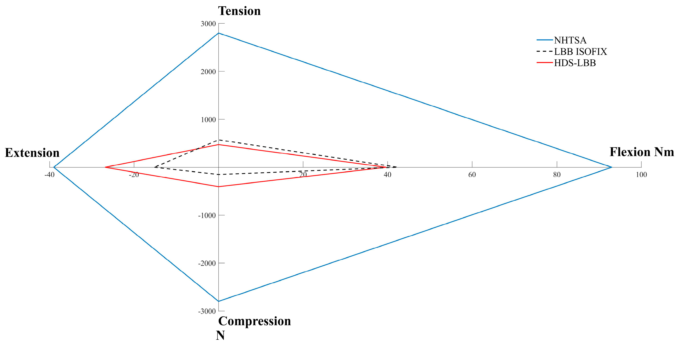
3.1. Head
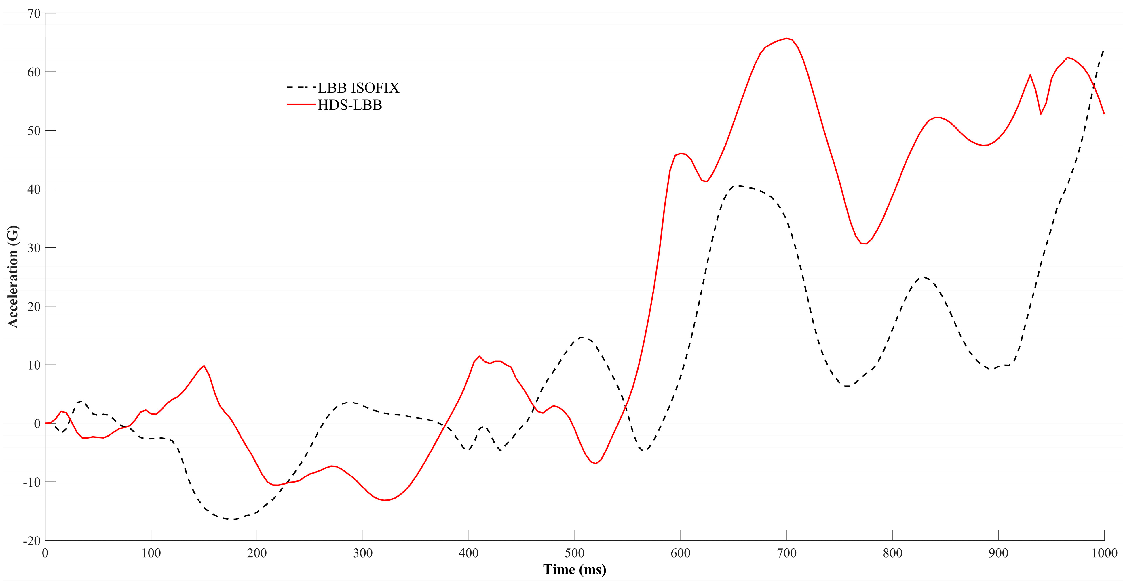
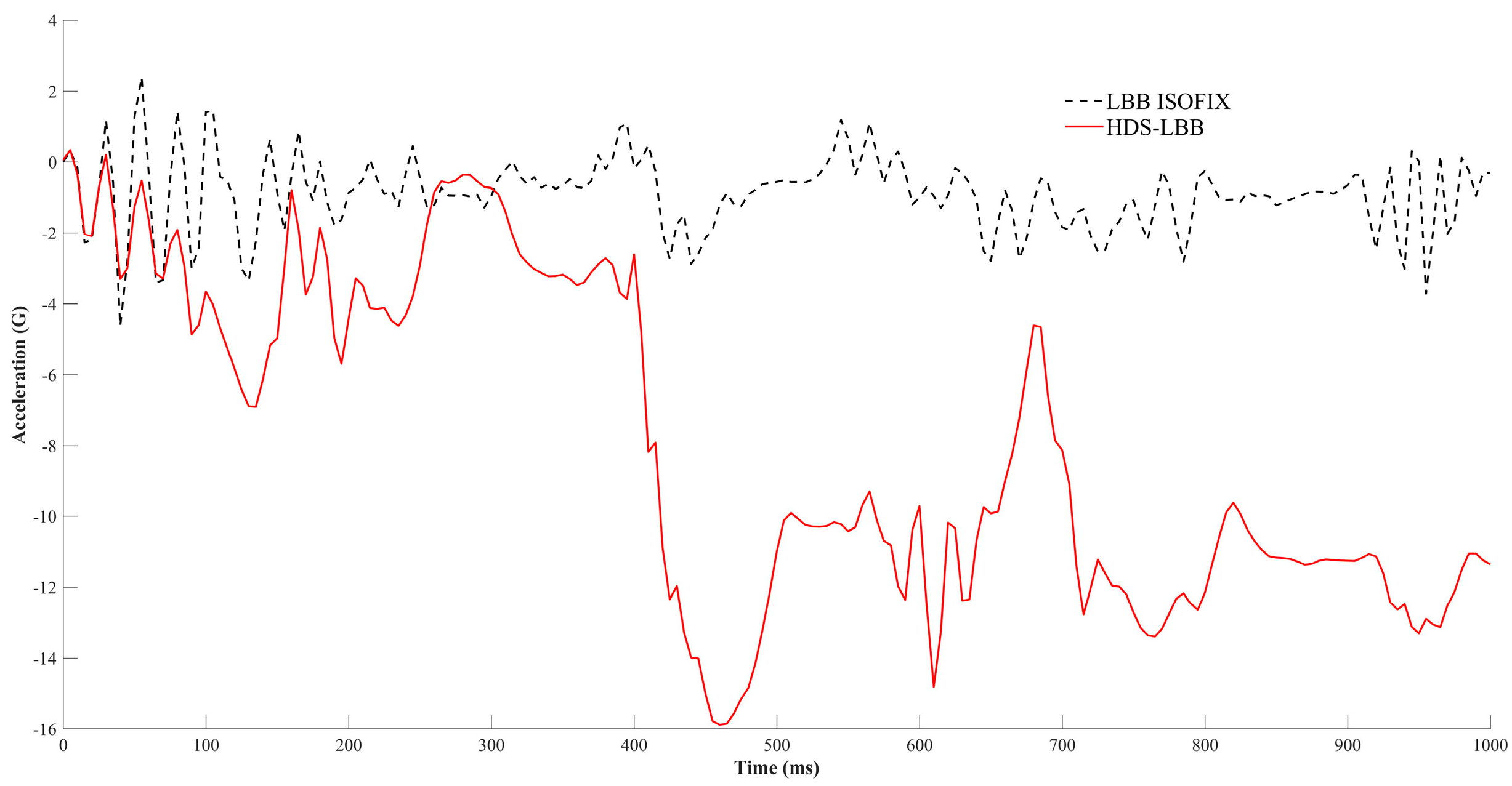
3.2. Thorax
4. Discussion
5. Conclusions
Author Contributions
Funding
Institutional Review Board Statement
Informed Consent Statement
Data Availability Statement
Acknowledgments
Conflicts of Interest
References
- Instituto Nacional de Estadística y Geografía (INEGI). Accidentes Por Tipo. 2023. Available online: https://www.inegi.org.mx/app/tabulados/interactivos/?pxq=ATUS_ATUS_4_63710dee-dbe8-45f2-b71b-01b7970b0966 (accessed on 2 August 2023).
- National Highway Traffic Safety Administration. Review of NMVCCS Rollover Variables in Support of Rollover Recon-Struction [DOT HS 811 235]; National Highway Traffic Safety Administration: Washington, DC, USA, 2010.
- El-Menyar, A.; Latifi, R.; Parchani, A.; Peralta, R.; Tuma, M.; Zarour, A.; Abdulrahman, H.; Al-Thani, H.; Asim, M.; El-Hennawy, H. Epidemiology, Causes and Prevention of Car Rollover Crashes with Ejection. Ann. Med. Health Sci. Res. 2014, 4, 495. [Google Scholar] [CrossRef] [PubMed]
- George, R.; John, L. Rollover Crash Study Vehicle: Design and Occupant Injuries; Monash University: Melbourne, Australia, 1994. [Google Scholar]
- Liu, S.; Fan, W.D.; Li, Y. Injury Severity Analysis of Rollover Crashes for Passenger Cars and Light Trucks Considering Temporal Stability: A Random Parameters Logit Approach with Heterogeneity in Mean and Variance. J. Saf. Res. 2021, 78, 276–291. [Google Scholar] [CrossRef] [PubMed]
- J2114_201102; SAE International Recommended Practice, Dolly Rollover Recommended Test Procedure. SAE Standard: Warrendale, PA, USA, 1993. [CrossRef]
- National Highway Traffic Safety Administration. Laboratory Test Procedure for FMVSS 208-14-Occupant Crash Protection; National Highway Traffic Safety Administration: Washington, DC, USA, 2008.
- Whitman, G.; Sicher, L.; Yannaccone, J.; Hooker, R. Dolly Rollover Testing of Child Safety Seats; SAE Technical Paper 2006-01-0914; SAE International: Warrendale, PA, USA, 2006. [Google Scholar] [CrossRef]
- Durbin, D.R.; Jermakian, J.S.; Kallan, M.J.; McCartt, A.T.; Arbogast, K.B.; Zonfrillo, M.R.; Myers, R.K. Rear Seat Safety: Variation in Protection by Occupant, Crash and Vehicle Characteristics. Accid. Anal. Prev. 2015, 80, 185–192. [Google Scholar] [CrossRef] [PubMed]
- Myers, R.K.; Lombardi, L.R.; Pfeiffer, M.R.; Curry, A.E. Restraint Use Characteristics among Crash-Involved Child Passengers: Identifying Opportunities to Enhance Optimal Restraint Use. Traffic Inj. Prev. 2022, 23, S213–S217. [Google Scholar] [CrossRef] [PubMed]
- Benedetti, M.; Klinich, K.D.; Manary, M.A.; Flannagan, C.A.C. Factors Affecting Child Injury Risk in Motor-Vehicle Crashes. Stapp Car Crash J. 2020, 63, 195–211. [Google Scholar]
- Durbin, D.R.; Chen, I.; Smith, R.; Elliott, M.R.; Winston, F.K. Effects of Seating Position and Appropriate Restraint Use on the Risk of Injury to Children in Motor Vehicle Crashes. Pediatrics 2005, 115, e305–e309. [Google Scholar] [CrossRef] [PubMed]
- García-España, J.F.; Durbin, D.R. Injuries to Belted Older Children in Motor Vehicle Crashes. Accid. Anal. Prev. 2008, 40, 2024–2028. [Google Scholar] [CrossRef] [PubMed]
- Valent, F.; McGwin, G.; Hardin, W.; Johnston, C.; Rue, L.W. Restraint Use and Injury Patterns among Children Involved in Motor Vehicle Collisions. J. Trauma Inj. Infect. Crit. Care 2002, 52, 745–751. [Google Scholar] [CrossRef] [PubMed]
- Rivara, F.P. Injuries and Death of Children in Rollover Motor Vehicle Crashes in the United States. Inj. Prev. 2003, 9, 76–80. [Google Scholar] [CrossRef] [PubMed]
- Center for Child Injury Prevention Studies. Injury Risk and Causation Scenarios of Children Involved in Rollover Crashes. Available online: https://cchips.research.chop.edu/injury-risk-and-causation-scenarios-of-children-involved-in-rollover-crashes (accessed on 6 December 2023).
- Martínez-Miranda, M.A.; Torres San Miguel, C.R.; Flores-Campos, J.A.; Ceccarelli, M. Numerical Simulation of a 2D Harmonic Oscillator as Coupling System for Child Restraint Systems (CRS). Mechanisms and Machine Science; Springer: Cham, Switzerland, 2021; Volume 91, pp. 492–502. [Google Scholar] [CrossRef]
- Cruz-Jaramillo, I.L.; Martínez-Sáez, L.; Torres-SanMiguel, C.R. Numerical Simulation of Mechanical Coupling for Low-Back Booster with a 6-Year-Old Child during a Crash Test. Appl. Sci. 2022, 12, 5350. [Google Scholar] [CrossRef]
- Holdampf, C.J.; Vangipuram, R. Vehicle Seat Interlock System. U.S. Patent No. 5,603,550, 18 February 1997. pp. 1–19. [Google Scholar]
- Lane, W.C., Jr. Apparatus with a Child Seat and an Energy Absorption Mechanism. U.S. Patent No. 5,685,603, 11 November 1996. pp. 1–20. [Google Scholar]
- Amesar, P.T.; Nakhla, S.; Przybylo, P.; Tobin, J.R. Energy Absorbing Tether for Child Safety Seat. U.S. Patent US-20090026815-A1, 28 January 2008. [Google Scholar]
- Wang, H. Energy Absorbing and Damping Device for Child Car Seat. European Patent EP3040234B1, 26 December 2013. [Google Scholar]
- Van Der Veer, E.; Van Mourik, O.; Van Houtert, R. Rotating Child Safety Seat. JUSTIA Patent 20130154318, 9 September 2012. [Google Scholar]
- Graham, S. Fundamentals of Mechanical Vibrations, 2nd ed.; McGraw-Hill: New York, NY, USA, 2016. [Google Scholar]
- Cruz-Jaramillo, I.L.; Torres-San Miguel, C.R.; Martínez-Sáez, L.; Ramírez-Vela, V.; Urriologoitia-Calderón, G.M. Numerical Low-Back Booster Analysis in a 6-Year-Old Infant during a Dolly Rollover Test. J. Adv. Transp. 2020, 2020, 5803623. [Google Scholar] [CrossRef]
- Marzougui, D.; Radwan, R.; Cui, C.; Kan, C.-D.; Opiela, K.S. Extended Validation of the Finite Element Model for the 2010 Toyota Yaris Passenger Sedan. In Proceedings of the Transportation Research Board 92nd Annual Meeting, Washington, DC, USA, 13–17 January 2013. [Google Scholar]
- Carrero, A. Simulación de Un Choque Lateral Con Dummy Con Cinturón Mediante LS-DYNA; Universidad Carlos III de Madrid Escuela Politécnica Superior: Madrid, Spain, 2011. [Google Scholar]
- Kang, S.; Chen, C.; Guha, S.; Paladugu, M.; Ramasamy, M.S.; Gade, L.; Zhu, F. LS-DYNA Belted Occupant Model. In Proceedings of the 15th International LS-DYNA Users Conference, Detroit, MI, USA, 10–14 June 2018. [Google Scholar]
- UNECE. Regulation No. 129 of the Economic Commission for Europe of the United Nations (UN/ECE)—Uniform Provisions Concerning the Approval of Enhanced Child Restraint Systems Used on Board of Motor Vehicles (ECRS); UNECE: Geneva, Switzerland, 2018. [Google Scholar]
- UNECE. UN Regulation No. 129 Increasing the Safety of Children in Vehicles; UNECE: Geneva, Switzerland, 2016. [Google Scholar]
- Callister, W.D.; Rethwisch, D.G. Materials Science and Engineering: An Introduction, 10th ed.; Wiley: Hoboken, NJ, USA, 2018. [Google Scholar]
- Tay, Y.Y.; Lim, C.S.; Lankarani, H.M. A Finite Element Analysis of High-Energy Absorption Cellular Materials in Enhancing Passive Safety of Road Vehicles in Side-Impact Accidents. Int. J. Crashworthiness 2014, 19, 288–300. [Google Scholar] [CrossRef]
- Beer, F.P.; Johnston, E.R.; DeWolf, J.T. Mecánica de Materiales, 8th ed.; McGraw Hill: New York, NY, USA, 2021. [Google Scholar]
- Hibbeler, C. Mecánica de Materiales, 9th ed.; Pearson: London, UK, 2017. [Google Scholar]
- Alamsyah; Sari, F.I.; Arifuddin, A.M.N.; Pawara, M.U.; Mubarak, A.A. Experimental Test of Tensile Strength of Barge Deck Plate Welded Joints. Int. J. Metacentre 2022, 2, 9–17. [Google Scholar]
- Chung, C.-H.; Choi, H.; Park, J. Local Collision Simulation of an SC Wall Using Energy Absorbing Steel. Nucl. Eng. Technol. 2013, 45, 553–564. [Google Scholar] [CrossRef]
- Lee Spring Resortes de Compresión. Available online: https://www.leespring.mx/es/resortes-de-compresion (accessed on 1 August 2023).
- DICTATOR. Amortiguadores de Impacto DICTATOR. Available online: https://dictator.es/herrajes-y-accionamientos/amortiguadores-hidraulicos/amortiguadores-de-impacto/amortiguadores-de-impacto#:~:text=Los%20amortiguadores%20de%20impacto%20de,en%20ambos%20lados%20(ZDH) (accessed on 1 August 2023).
- Gavelin, A.; Lindquist, M.; Oldenburg, M. Modelling and Simulation of Seat-Integrated Safety Belts Including Studies of Pelvis and Torso Responses in Frontal Crashes. Int. J. Crashworthiness 2007, 12, 367–379. [Google Scholar] [CrossRef]
- Reed, W.S.; Keskin, A.T. Vehicular Deceleration and Its Relationship to Friction; SAE Technical Paper 890736; SAE International: Warrendale, PA, USA, 1989. [Google Scholar] [CrossRef]
- Eppinger, R.; Sun, E.; Bandak, F.; Haffner, M.; Khaewpong, N.; Maltese, M.; Kuppa, S.; Nguyen, T.; Takhounts, E.; Tannous, R.; et al. Development of Improved Injury Criteria for the Assessment of Advanced Automotive Restraint Systems-II; National Highway Traffic Safety Administration: Washington, DC, USA, 1999.
- Wismans, J.; Waagmeester, K.; Le Claire, M.; Hynd, D.; De Jager, K.; Palisson, A.; van Ratingen, M.; Trosseille, X. Q-Dummies Report: Advanced Child Dummies and Injury Criteria for Frontal Impact; EEVC: London, UK, 2018. [Google Scholar]


| Test Speed | 13.34 m/s |
| Time interval | 1–1000 ms |
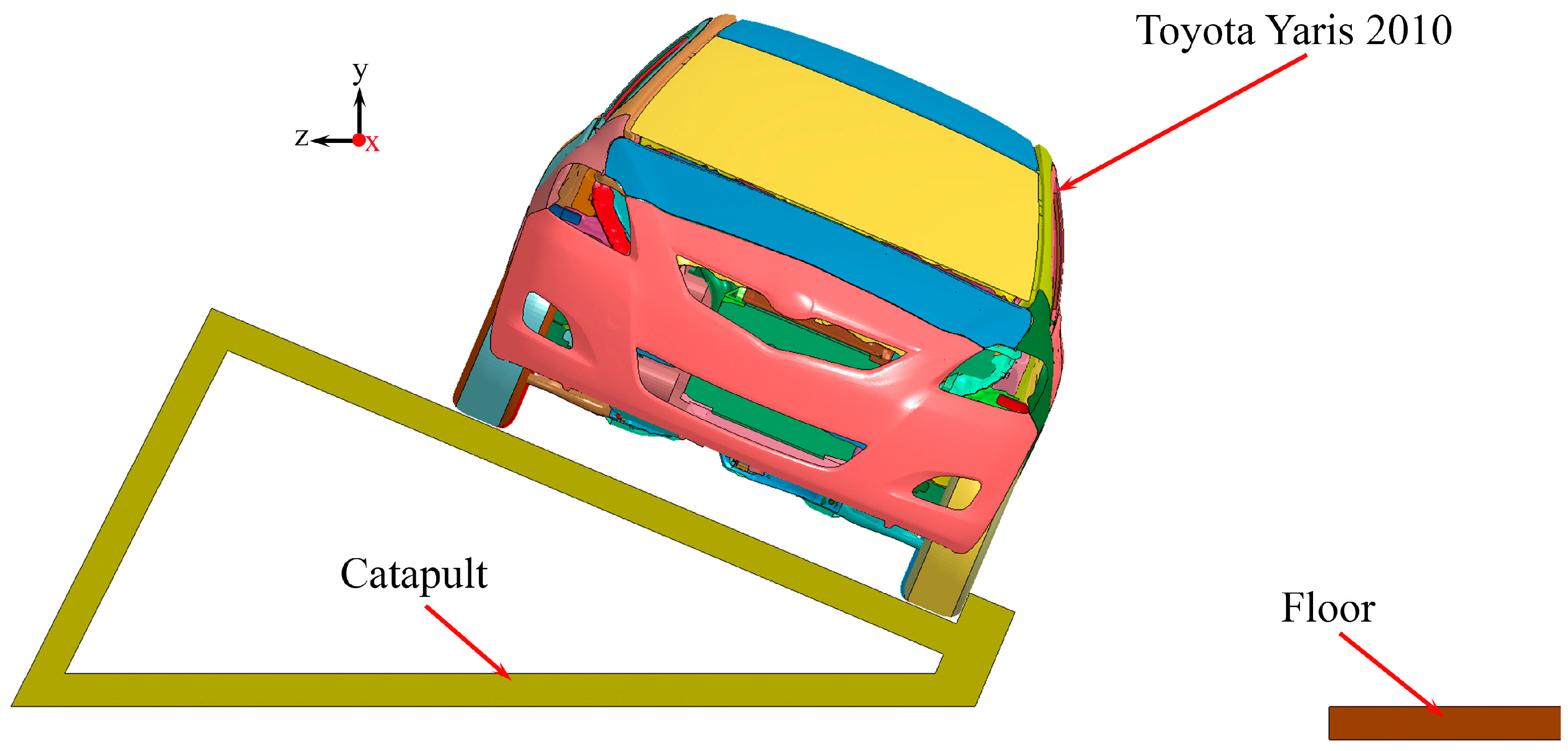
| Car | Toyota Yaris 2010 |
| Car weight | 1100 kg |
| Roll direction | Right passenger side |
| Component | Subcomponent | Mesh Formulation | Type Elements | Element Formulation | Nodes | Elements |
|---|---|---|---|---|---|---|
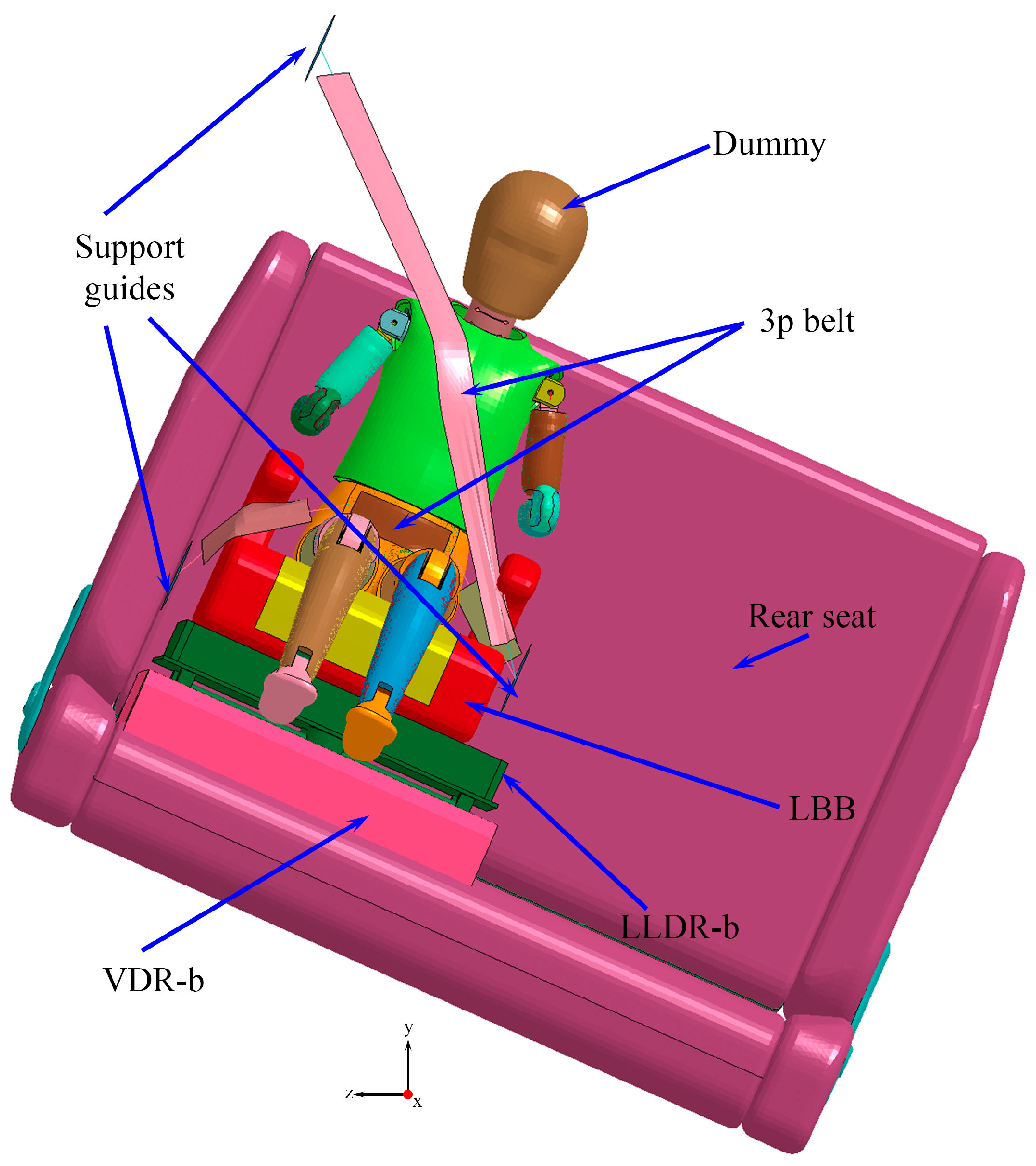
| LBB | Support material | Tetrahedral | Solid | Constant stress solid element | 21,156 | 92,028 |
| LBB cushioning | Tetrahedral | Solid | Constant stress solid element | 3510 | 10,028 | |
| Seatbelt | Lap belt and shoulder belt | Linear Triangle | Shell (Bidimensional) | Belytschko–Tsay | 667 | 1168 |
| Seat | Steel support | Tetrahedral | Solid | Constant stress solid element | 30,852 | 92,118 |
| Seat cushioning | Tetrahedral | Solid | Constant stress solid element | 183,855 | 827,071 | |
| Harmonic Device System (HDS) | Longitudinal–lateral displacement reduction box (LLDR-b) | Hexahedral | Solid | Constant stress solid element | 106,147 | 69,199 |
| Vertical displacement reduction box (VDR-b) | Hexahedral | Solid | Constant stress solid element | 240,294 | 208,335 |
| Material | Constitutive Model Selected in LS-DYNA | Density | Young’s Modulus (GPa) | Yield Strength (GPa) | Poisson’s Ratio |
|---|---|---|---|---|---|
| Steel | RIGID (020) | 210 | 0.6 | 0.3 | |
| Polypropylene [31] | ELASTIC (001) | 1.35 | 0.036 | 0.312 | |
| Foam DAX 55 [32] | LOW_DENSITY_FOAM (057) | --- | 0.31 | ||
| Aluminum 1100-H14 [33] | ELASTIC (001) | 70 | 0.095 | 0.33 | |
| ASTM A36 steel [34,35,36] | PLASTIC_KINEMATIC (003) | 200 | 0.25 | 0.32 | |
| Concrete [34] | RIGID (020) | 29 | --- | 0.15 |
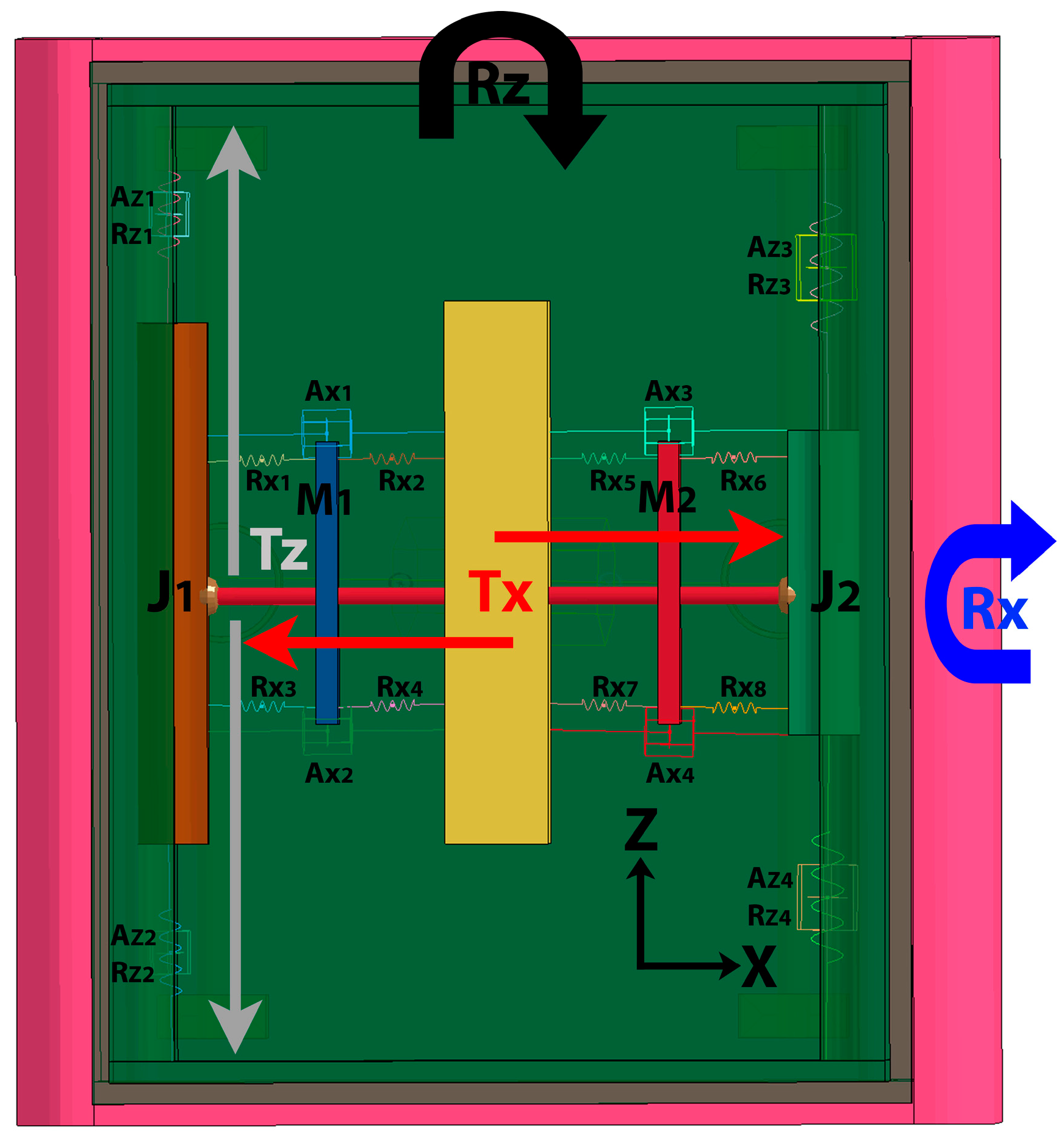
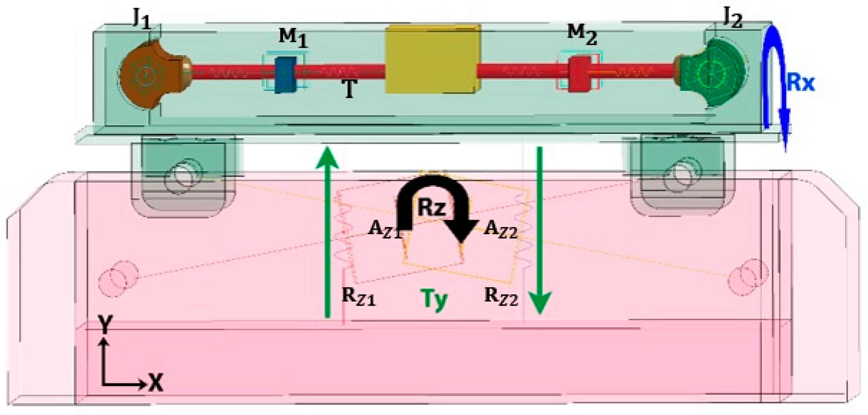
| Device | ID | Value | Length (mm) |
|---|---|---|---|
| Dampers | 0.015 | 150 | |
| 0.015 | 100 | ||
| 0.015 | 150 | ||
| 0.04 | 250 | ||
| Springs | 50 | ||
| 100 | |||
| 150 | |||
| 275 |
| Subsystem 1 | Subsystem 2 | LS DYNA CARD Selected |
|---|---|---|
| Tires | Catapult | CONTACT_AUTOMATIC SURFACE TO SURFACE |
| Vehicle | Floor | CONTACT_AUTOMATIC SURFACE TO SURFACE |
| Rear seat | Child dummy | CONTACT_AUTOMATIC SURFACE TO SURFACE |
| Seatbelt | Child dummy | CONTACT_AUTOMATIC SURFACE TO SURFACE |
| Mechanical coupling | Child dummy | CONTACT_AUTOMATIC SURFACE TO SURFACE |
| Mechanical coupling | Rear seat | CONTACT_AUTOMATIC SURFACE TO SURFACE |
| Injury Metrics | IARVS | ||||||
|---|---|---|---|---|---|---|---|
| Units | Values from the Numerical Simulations Performed | NHTSA Threshold [41] | EEVC [42] | ||||
| HDS-LBB | LBB-ISOFIX | UN R94 | AIS > −3 20% LR | AIS > −3 50% LR | |||
| HIC15 | --- | 144 | 156 | 700 | 986 | 1083 | 1389 |
| Nij | --- | 0.833 TE | 0.443—TE 0.660—TF 0.510—CE 0.594—CF | 1 | --- | --- | --- |
| Neck force (Fz) | N | 404.41 T | 150.64 | 2800 T 2800 C | 1824 | 2101 | 2304 |
| Neck moment (My) | Nm | 26.86 E | 15.17 | 93 F 39 E | 94 | 118 | 143 |
| Chest deflection | mm | 14 | 5 | 40 | 42 | 33 | 49 |
| Thorax acceleration | G’s | 58 | 25 | 60 | --- | --- | --- |
Disclaimer/Publisher’s Note: The statements, opinions and data contained in all publications are solely those of the individual author(s) and contributor(s) and not of MDPI and/or the editor(s). MDPI and/or the editor(s) disclaim responsibility for any injury to people or property resulting from any ideas, methods, instructions or products referred to in the content. |
© 2024 by the authors. Licensee MDPI, Basel, Switzerland. This article is an open access article distributed under the terms and conditions of the Creative Commons Attribution (CC BY) license (https://creativecommons.org/licenses/by/4.0/).
Share and Cite
Cruz-Jaramillo, I.L.; Torres-Ariza, J.L.; Grave-Capistrán, M.A.; Alcántara-Arreola, E.A.; Espinoza-Garcés, C.A.; Torres-SanMiguel, C.R. Numerical Dolly Rollover Evaluation Using a Damping-Harmonic System with a Low Back Booster to Reduce Injuries in a Six-Year-Old Child. Safety 2024, 10, 53. https://doi.org/10.3390/safety10020053
Cruz-Jaramillo IL, Torres-Ariza JL, Grave-Capistrán MA, Alcántara-Arreola EA, Espinoza-Garcés CA, Torres-SanMiguel CR. Numerical Dolly Rollover Evaluation Using a Damping-Harmonic System with a Low Back Booster to Reduce Injuries in a Six-Year-Old Child. Safety. 2024; 10(2):53. https://doi.org/10.3390/safety10020053
Chicago/Turabian StyleCruz-Jaramillo, Ivan Lenin, José Luis Torres-Ariza, Mario Alberto Grave-Capistrán, Elliot Alonso Alcántara-Arreola, Carlos Alberto Espinoza-Garcés, and Christopher René Torres-SanMiguel. 2024. "Numerical Dolly Rollover Evaluation Using a Damping-Harmonic System with a Low Back Booster to Reduce Injuries in a Six-Year-Old Child" Safety 10, no. 2: 53. https://doi.org/10.3390/safety10020053
APA StyleCruz-Jaramillo, I. L., Torres-Ariza, J. L., Grave-Capistrán, M. A., Alcántara-Arreola, E. A., Espinoza-Garcés, C. A., & Torres-SanMiguel, C. R. (2024). Numerical Dolly Rollover Evaluation Using a Damping-Harmonic System with a Low Back Booster to Reduce Injuries in a Six-Year-Old Child. Safety, 10(2), 53. https://doi.org/10.3390/safety10020053