
Mechanics of Bio-Inspired Protective Scales


Abstract
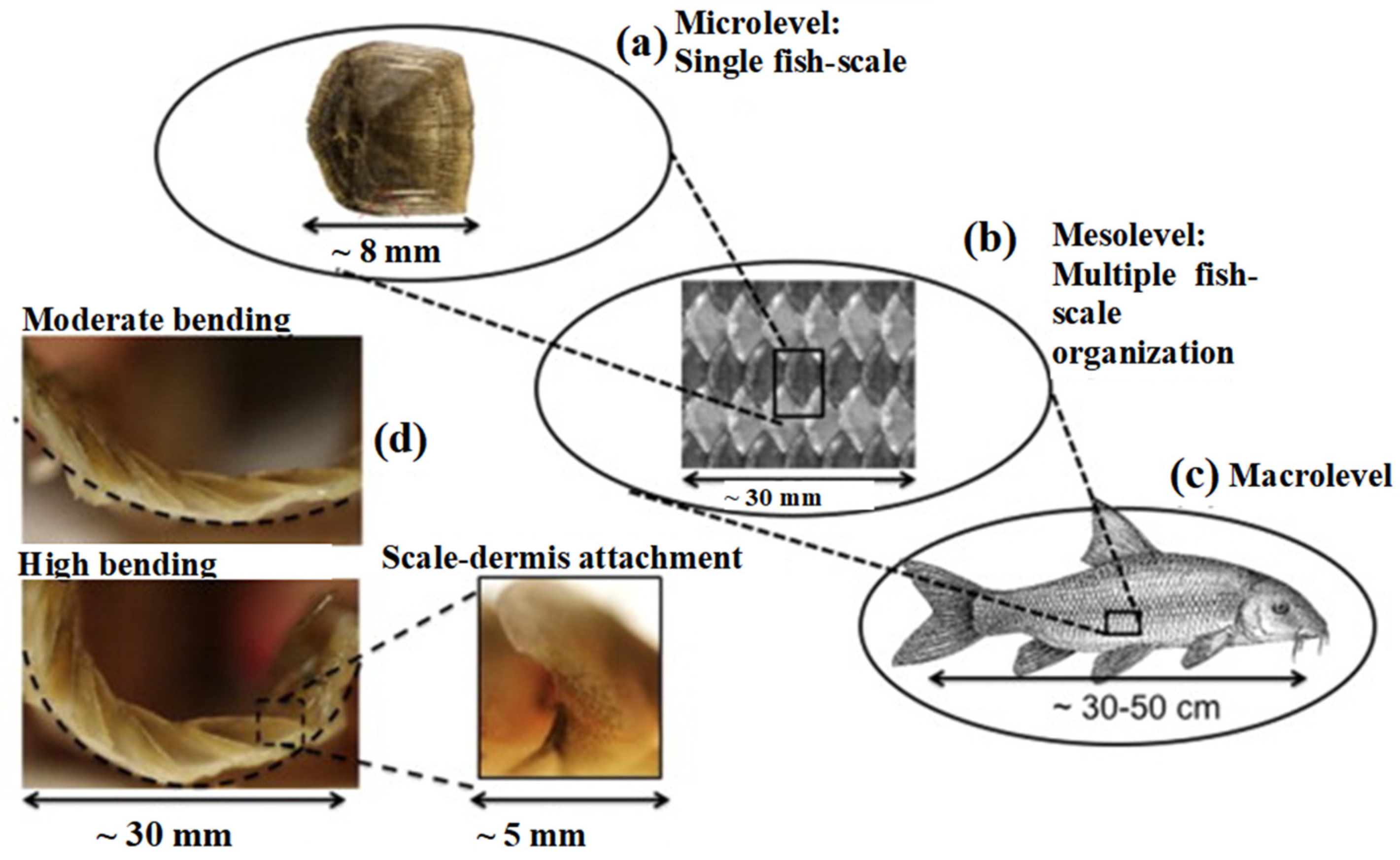
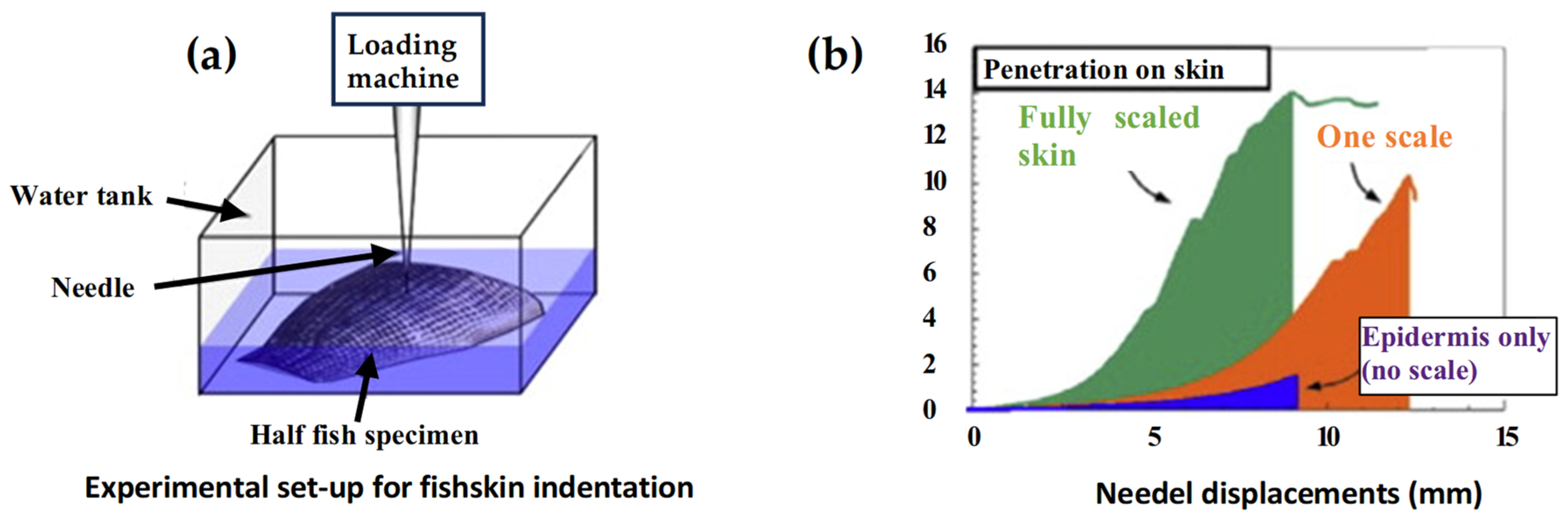
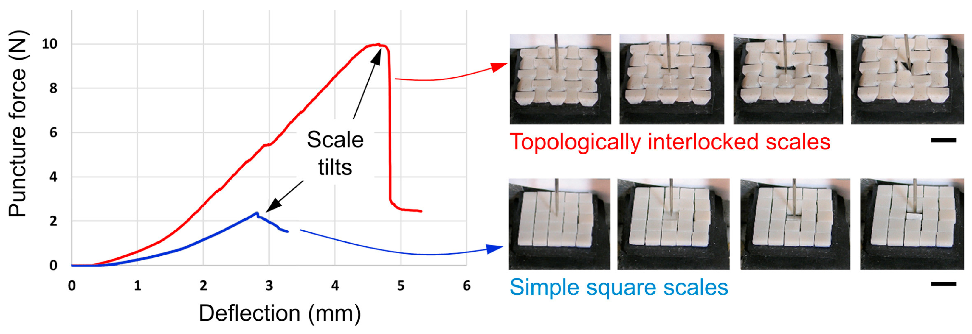
:1. Introduction
2. Materials and Methods
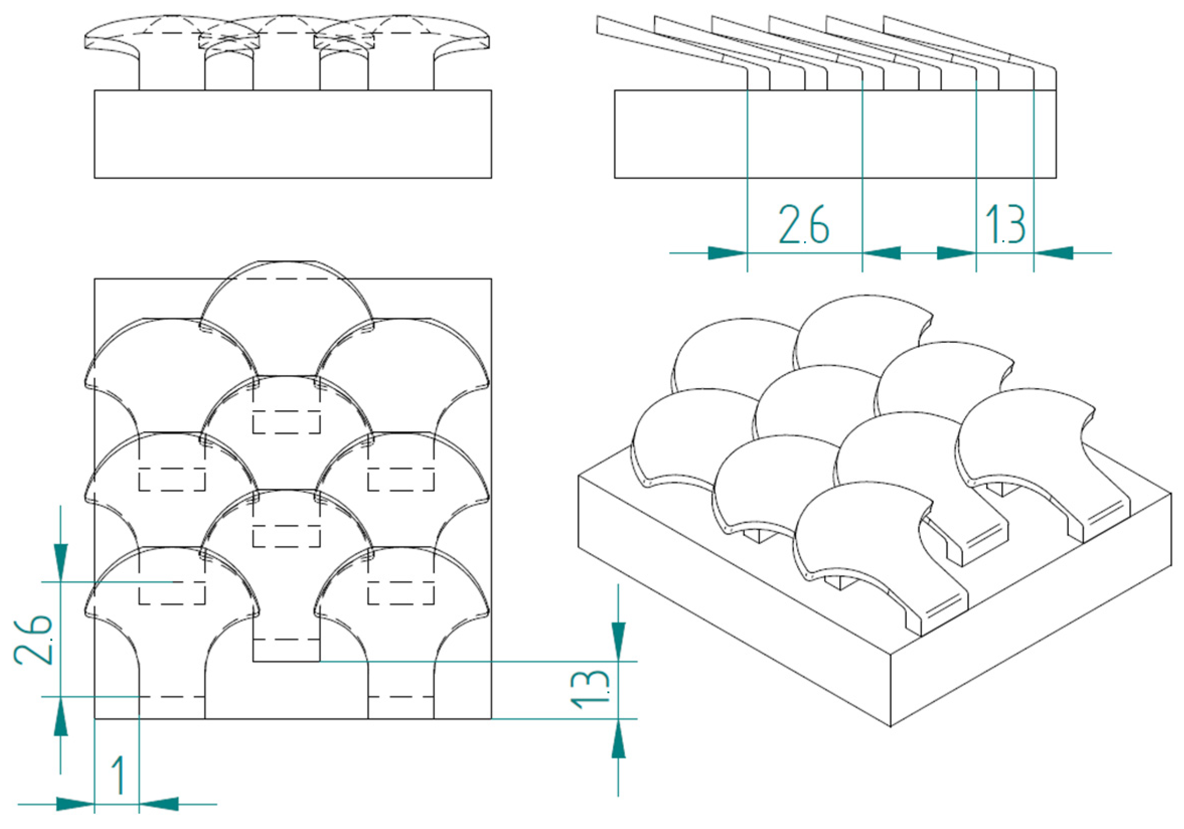
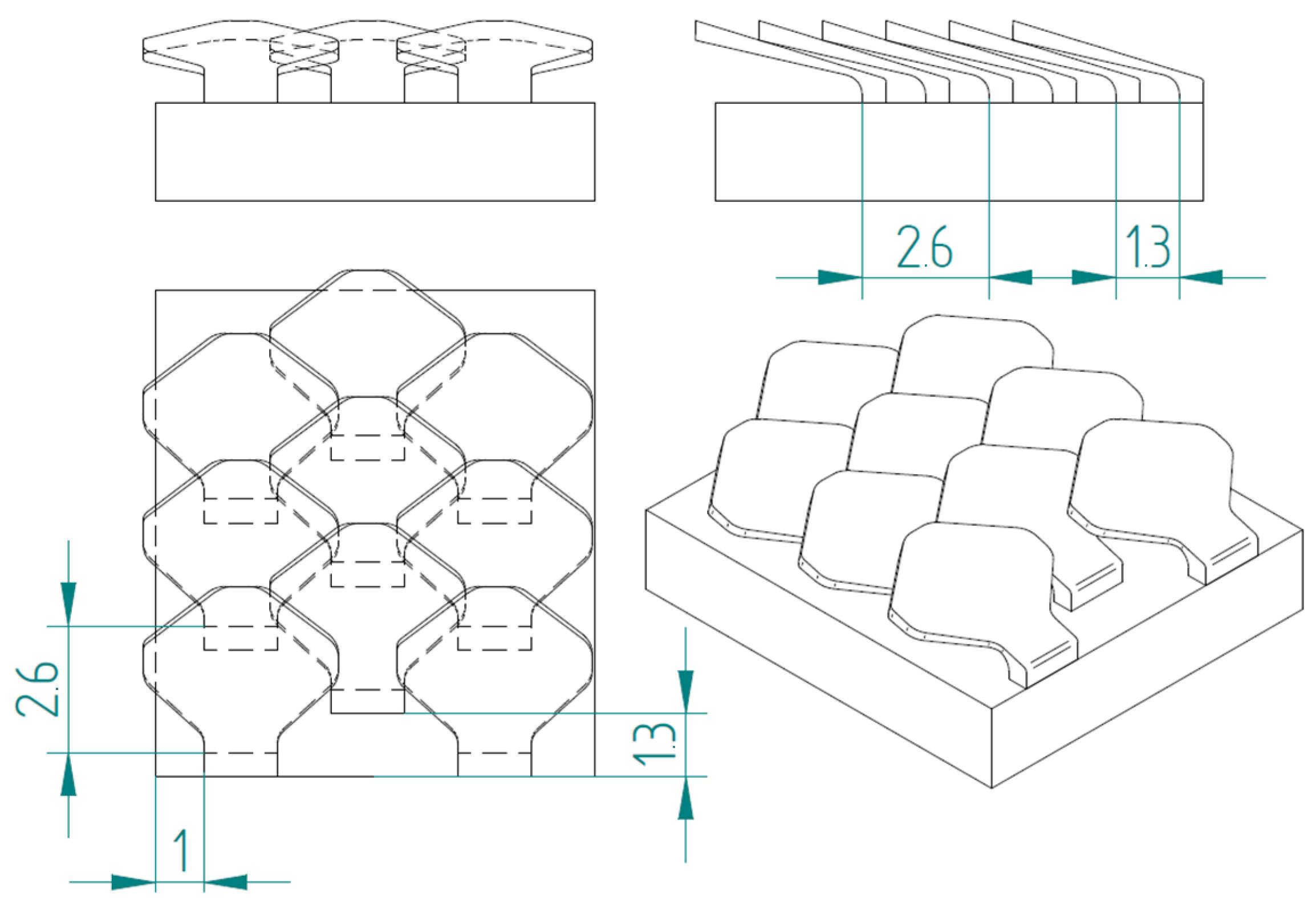
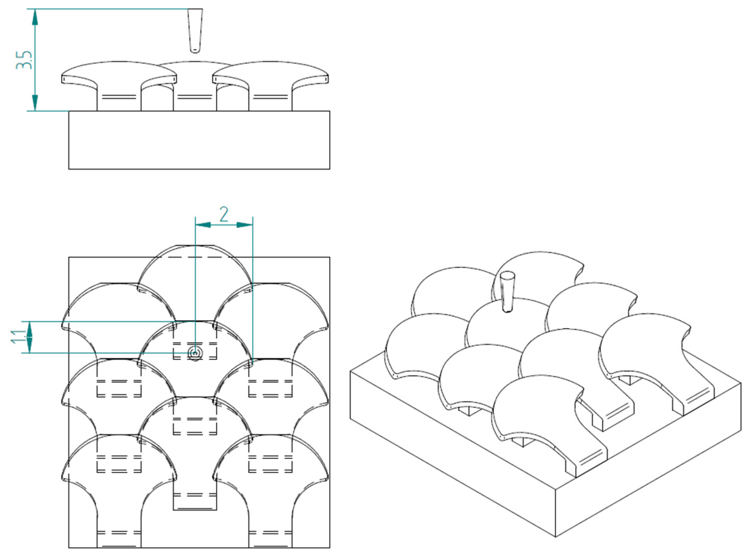
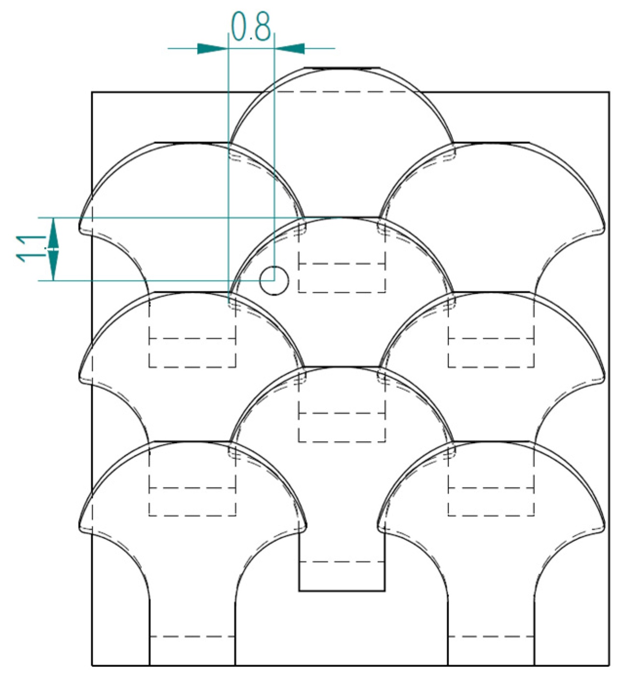
2.1. Novel Scale Models
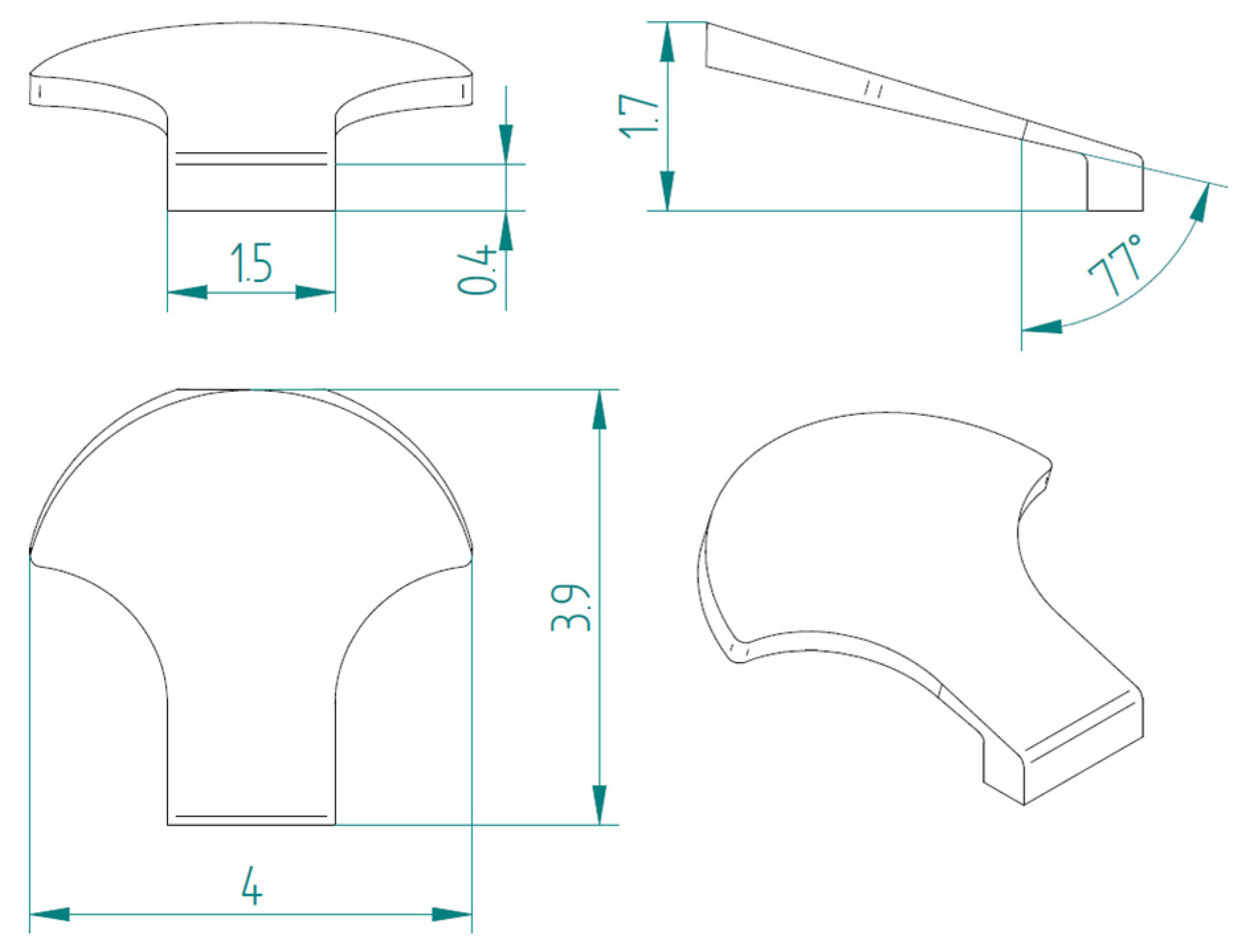
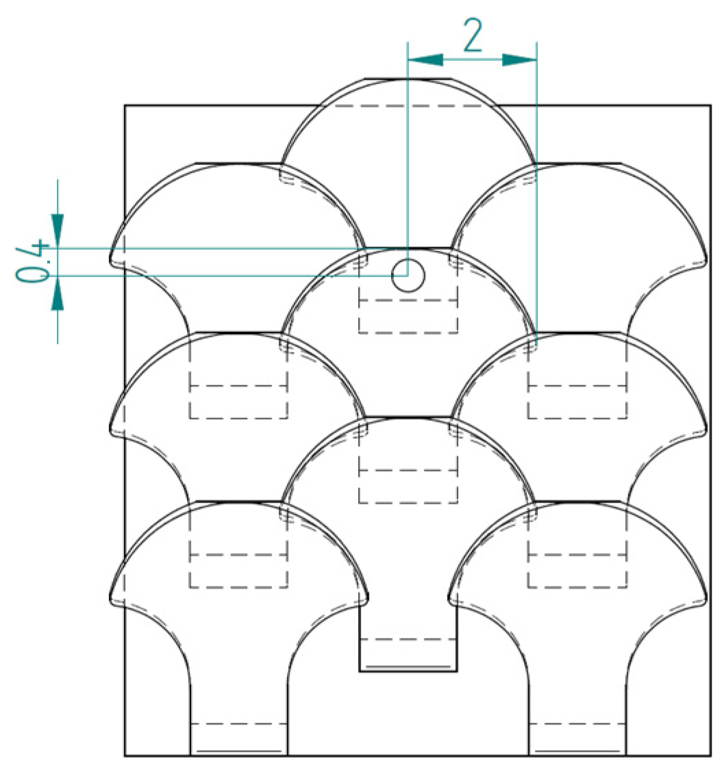
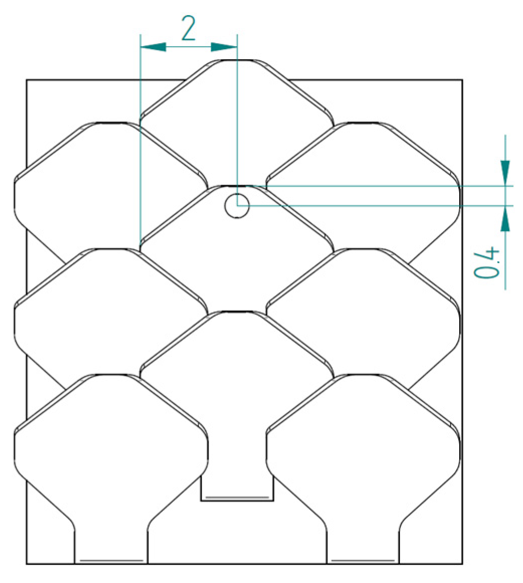
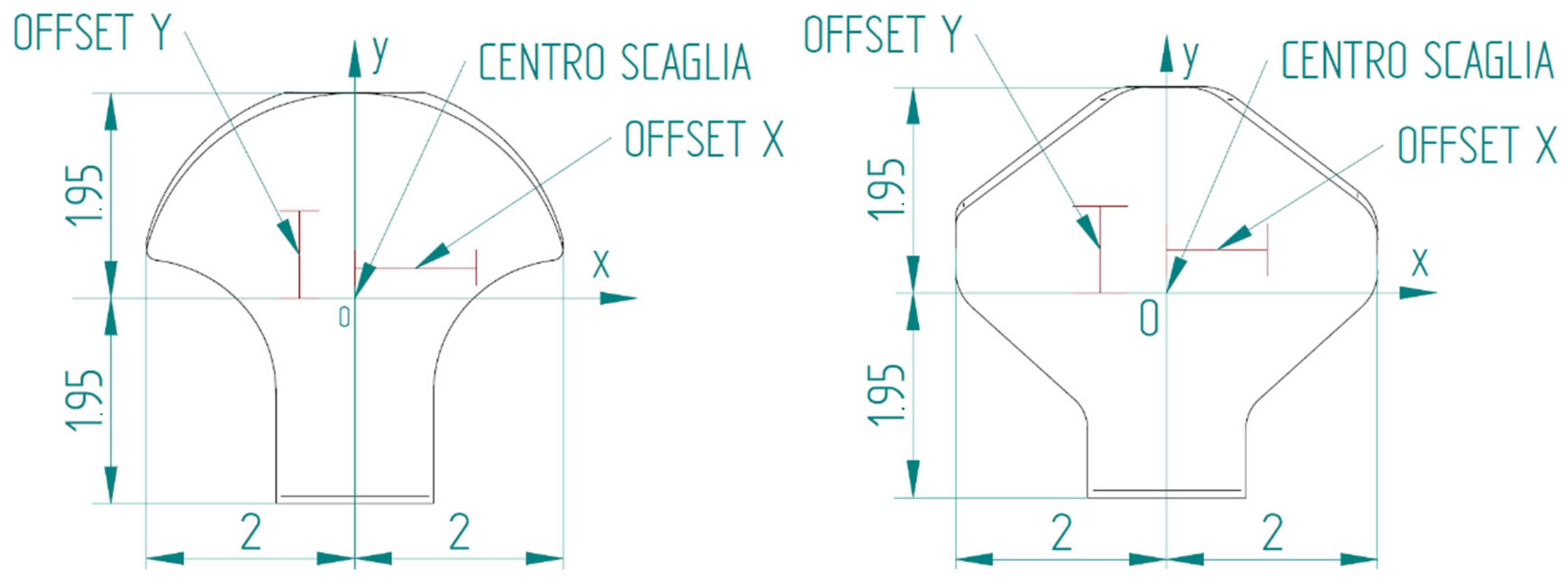
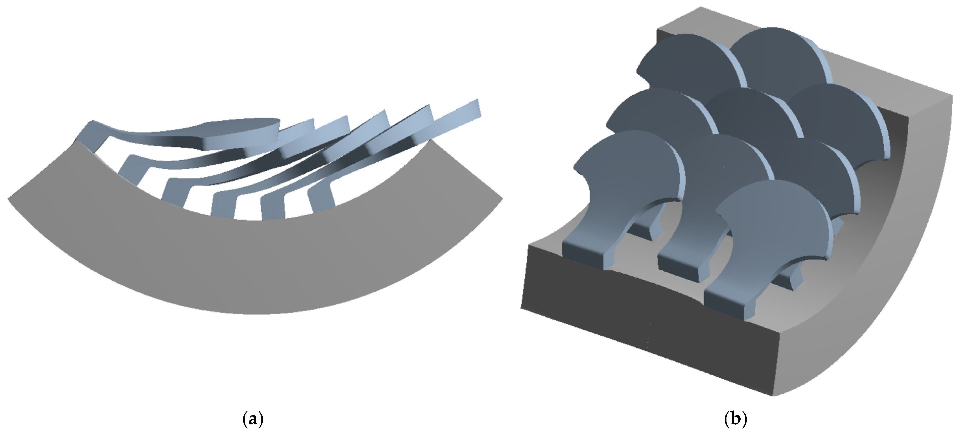
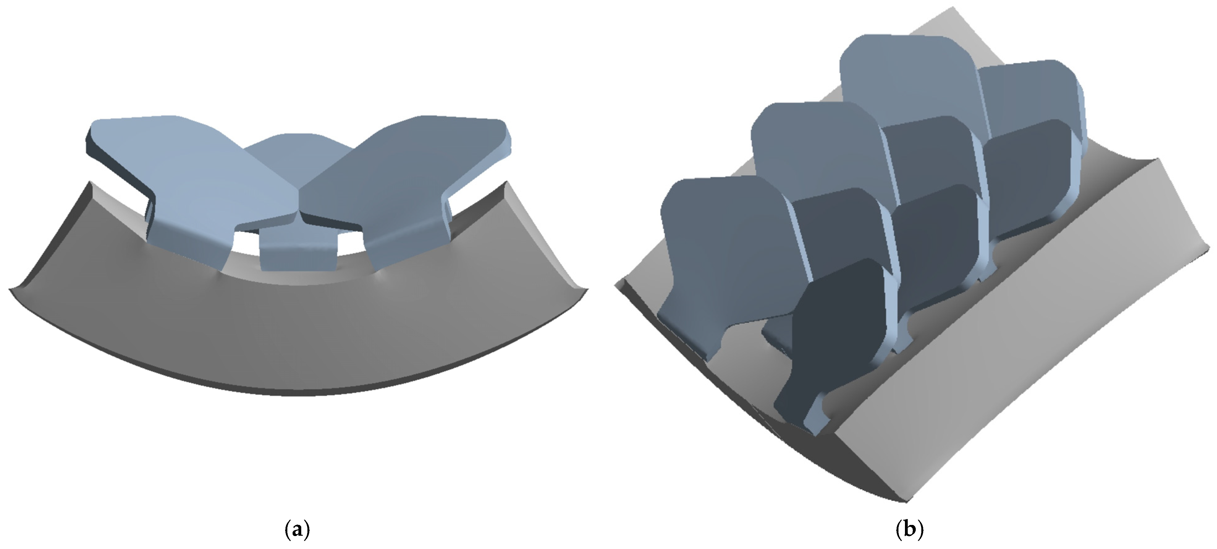
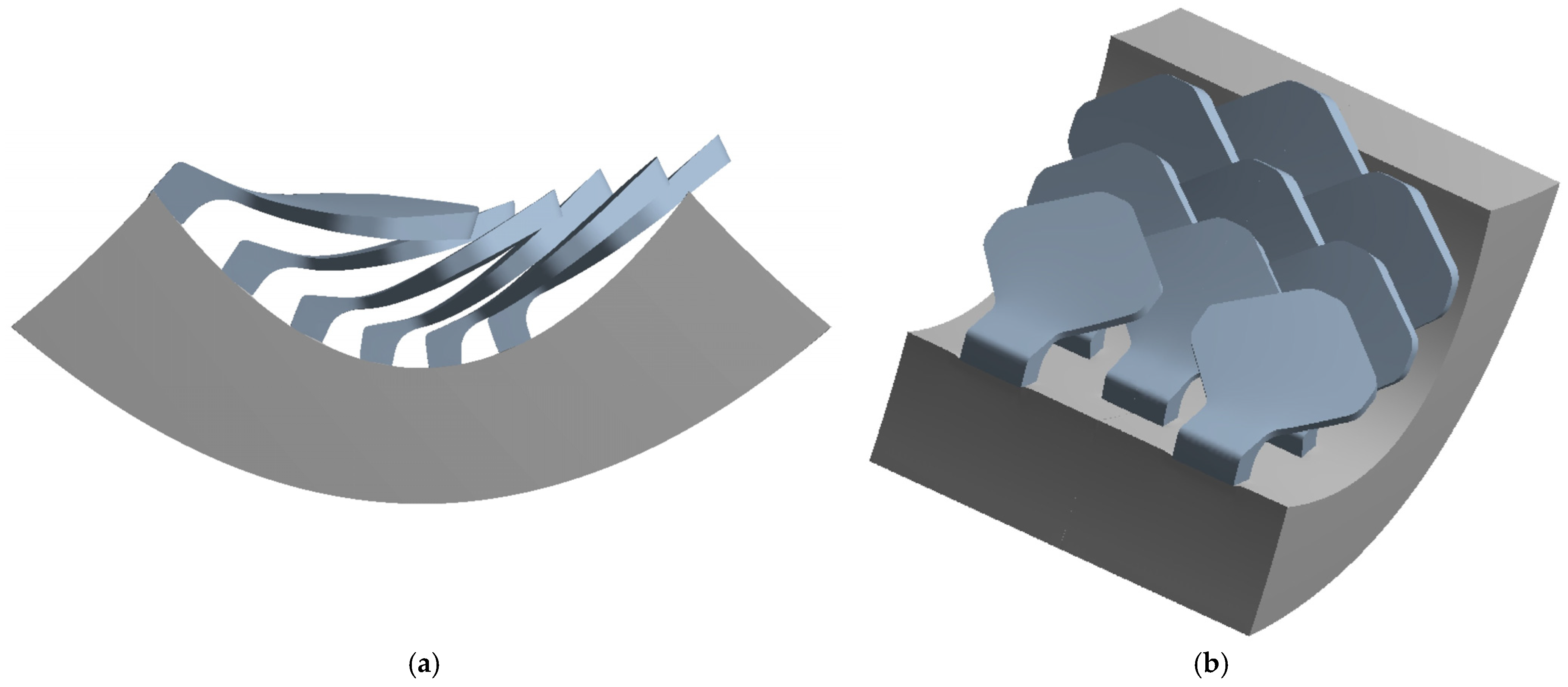
2.1.1. Type 1 Bio-Inspired Scale
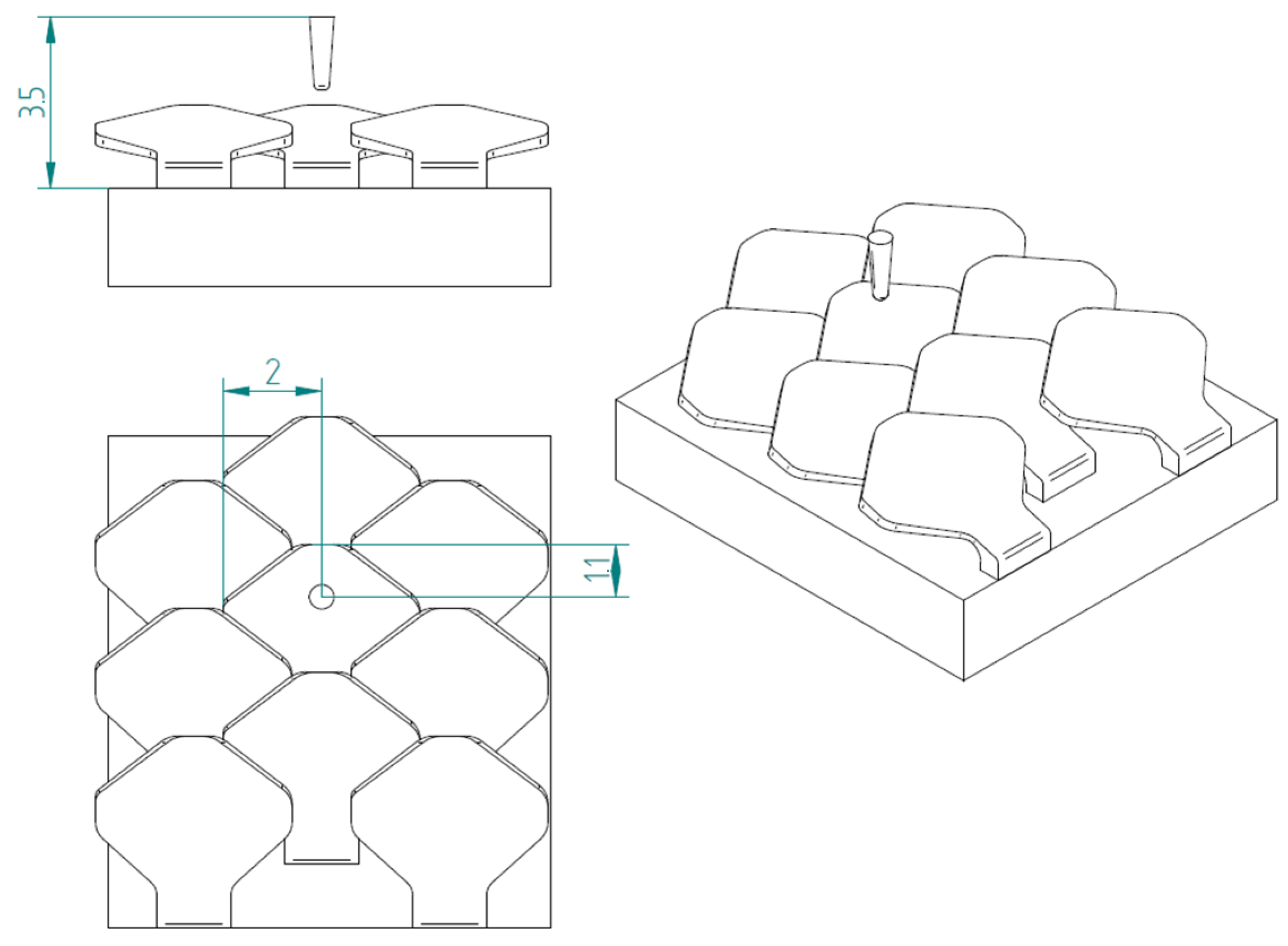
2.1.2. Type 2 Bio-Inspired Scale
2.1.3. Substrate
2.2. Numerical Method
2.2.1. Material Properties
- Density ρ = 1040 kg/m3;
- Young’s longitudinal modulus of elasticity E = 3 GPa = 3000 MPa;
- Poisson coefficient ν = 0.35.
- Density ρ = 1200 kg/m3;
- Young’s longitudinal modulus of elasticity E = 0.5 GPa = 500 MPa;
- Poisson’s ratio ν = 0.4.
- Density ρ = 7850 kg/m3;
- Young’s longitudinal modulus of elasticity E = 200 GPa = 200,000 MPa;
- Poisson’s ratio ν = 0.3;
- Breaking strength σr = 460 MPa.
2.2.2. Finite Element Model
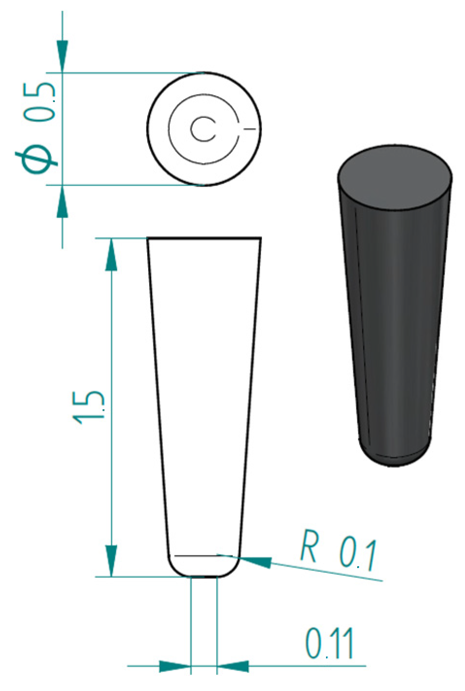
2.2.3. Puncture Resistance Test
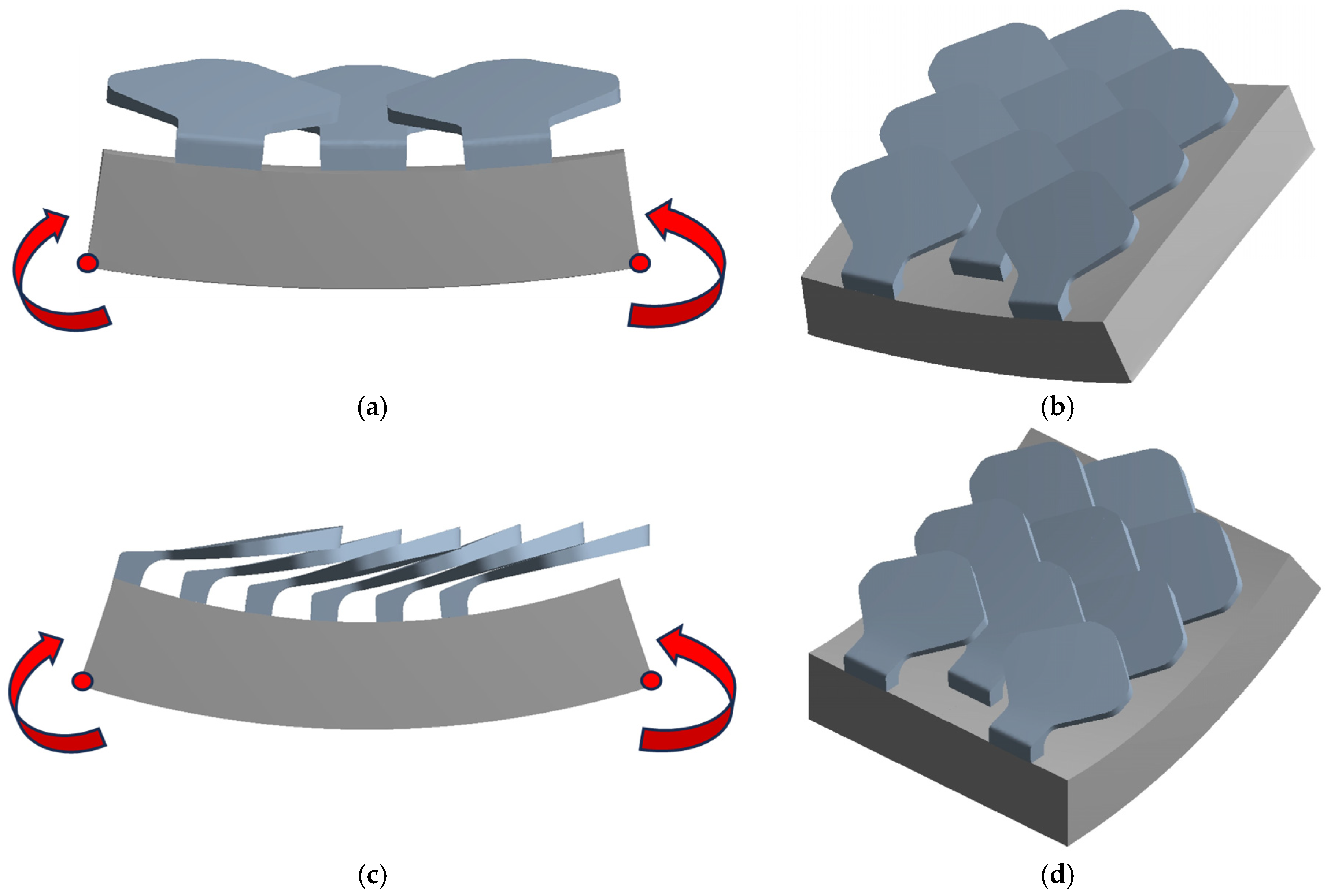
2.2.4. Flexural Test
3. Results
3.1. Type 1 Bio-Inspired Scale
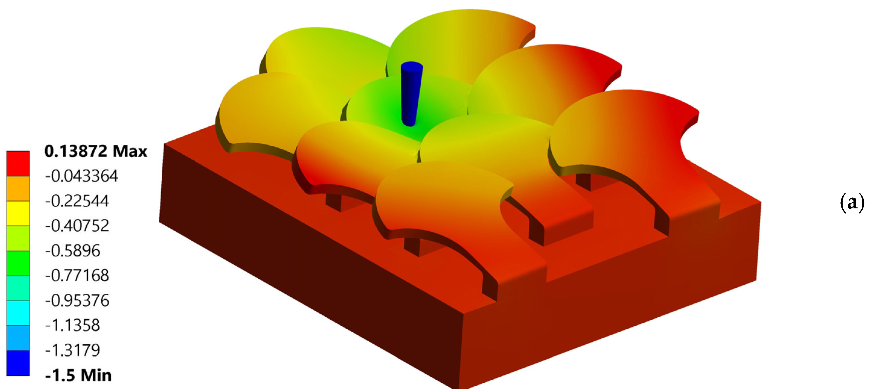
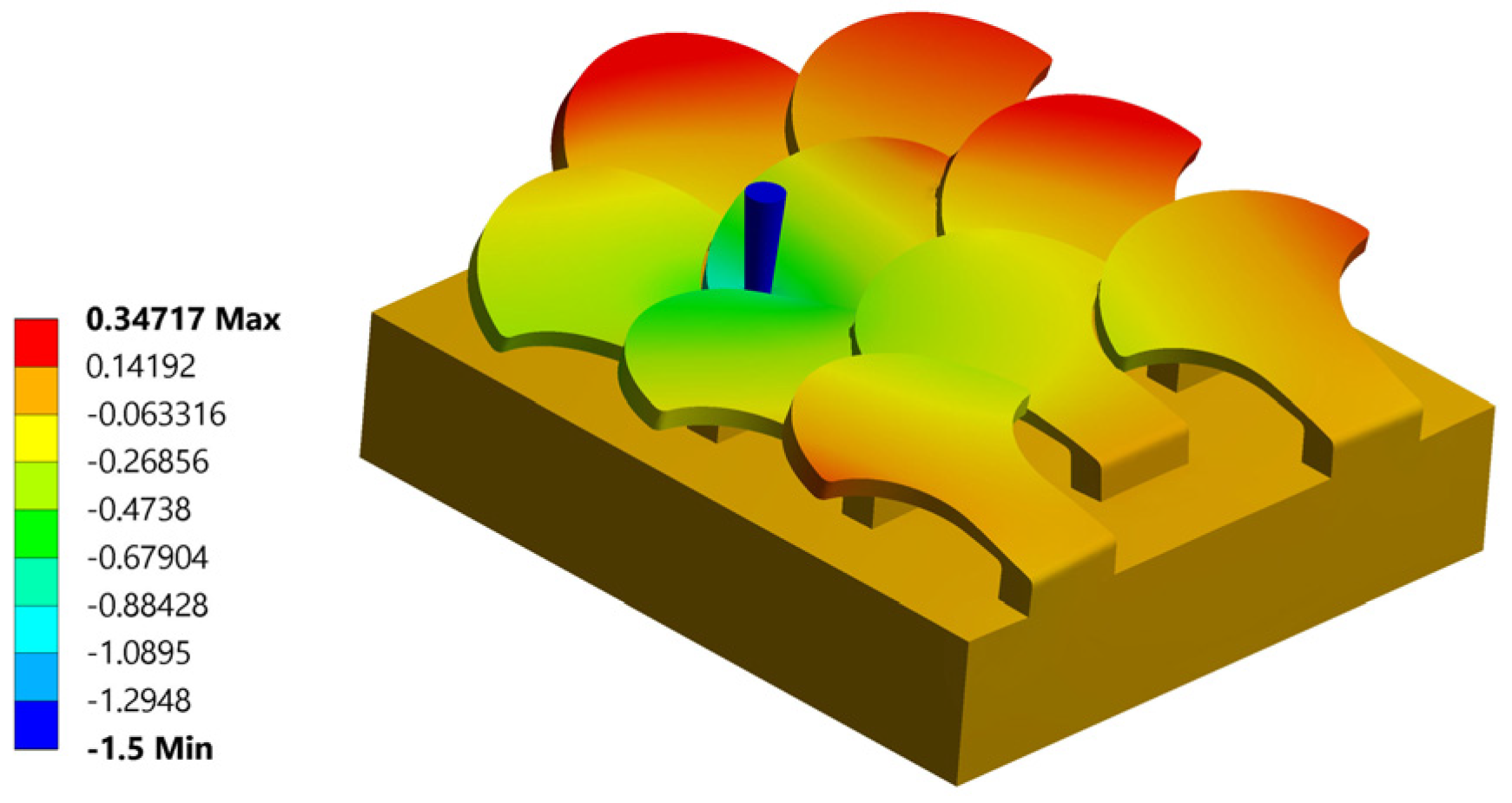
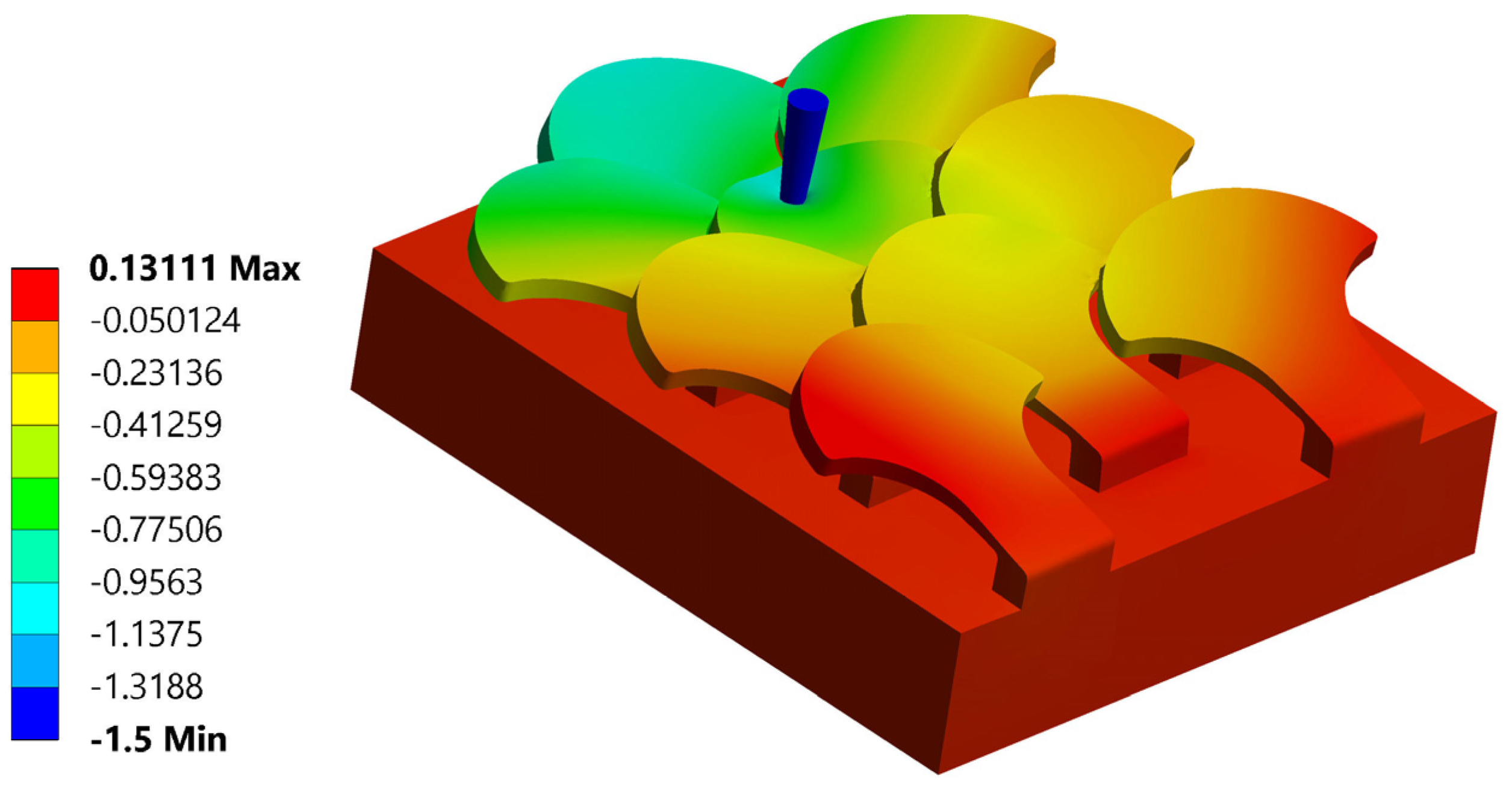
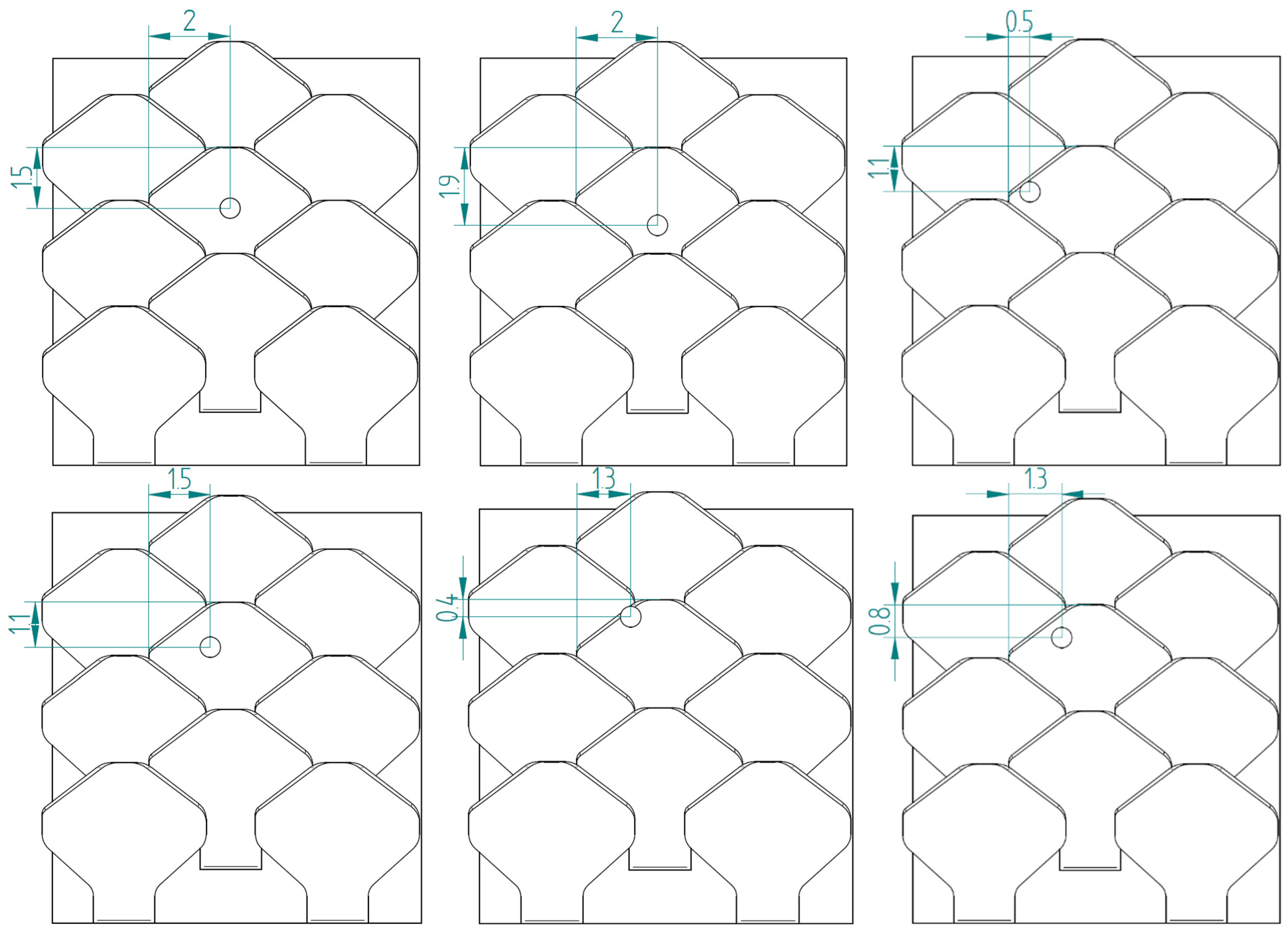
3.1.1. Simulation Number 1: Tip at the Center of the Scale
3.1.2. Simulation Number 2: Tip Near the Left Edge of the Scale
3.1.3. Simulation Number 3: Tip Near the Upper Edge of the Scale
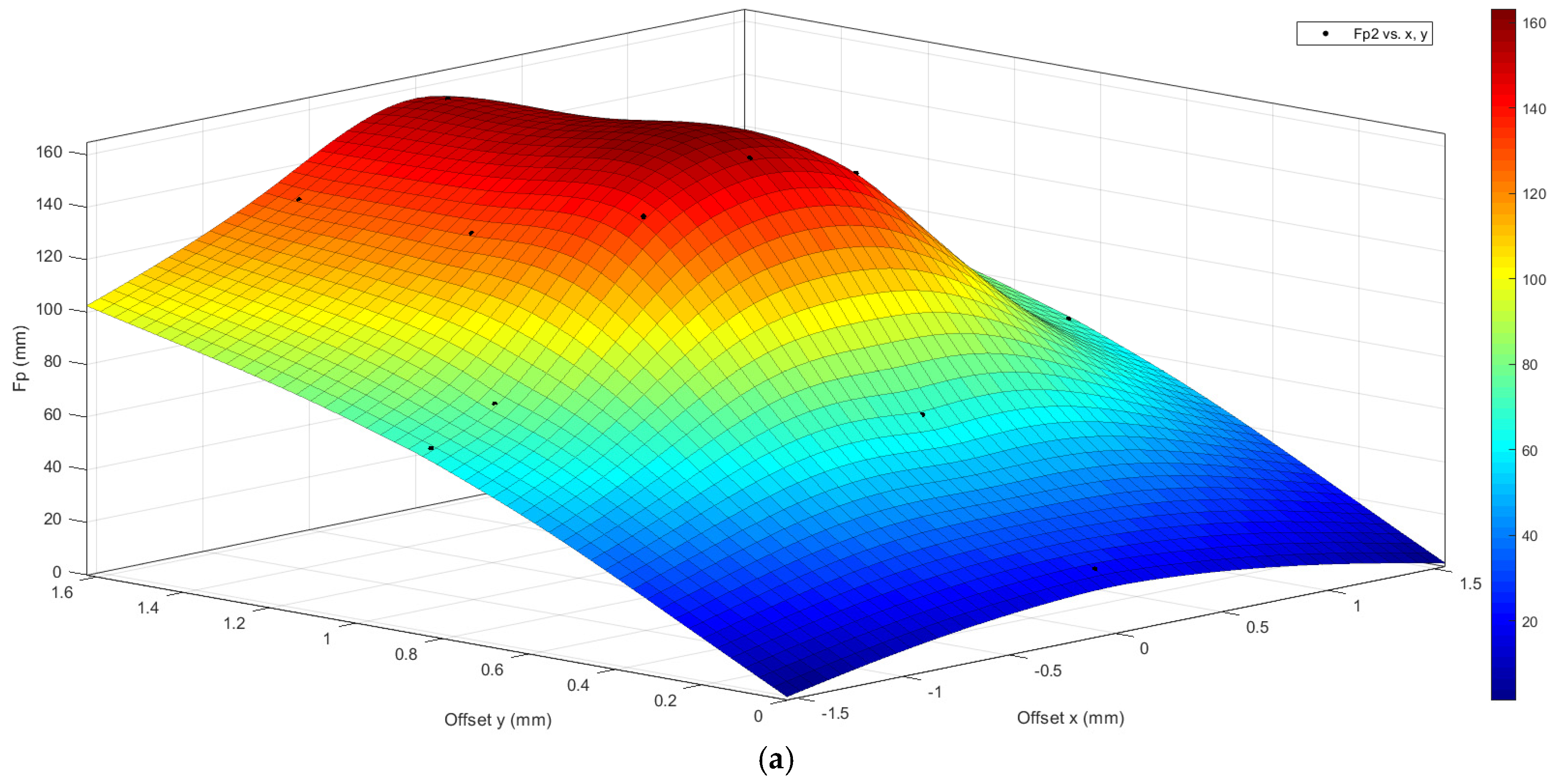
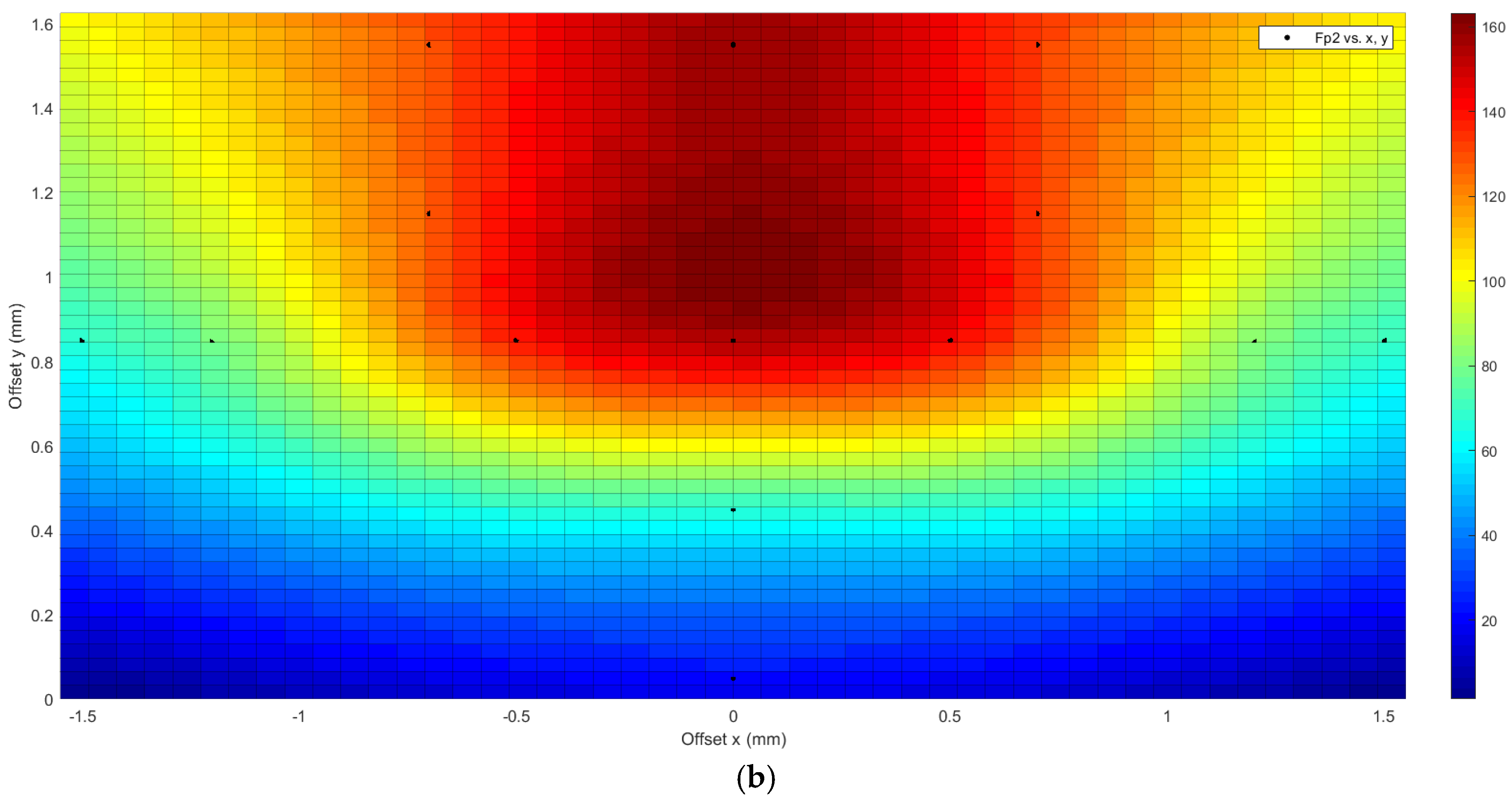
3.2. Type 2 Bio-Inspired Scale Structure
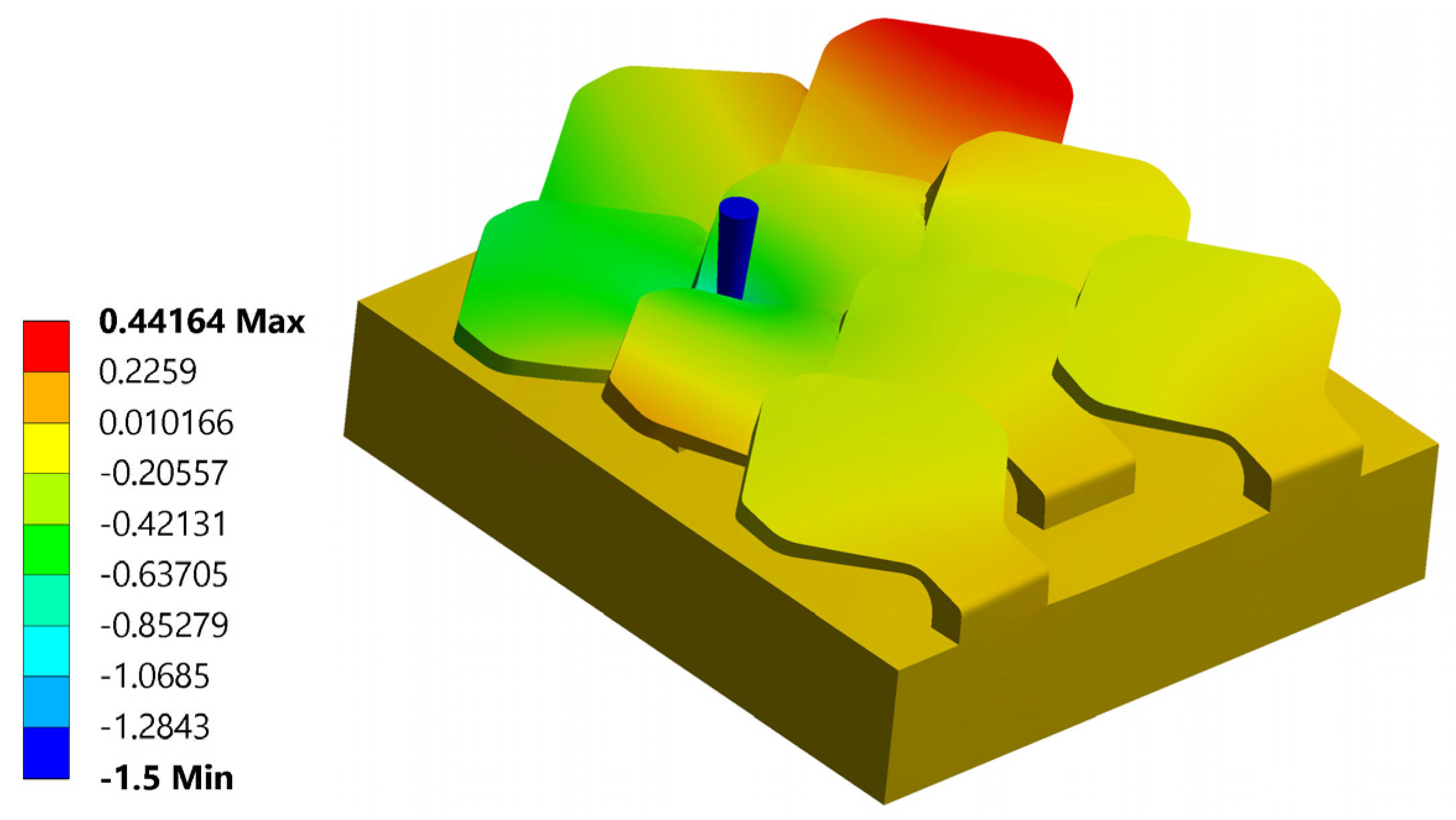
3.2.1. Simulation Number 1: Tip Near the Center of the Scale
3.2.2. Simulation Number 2: Tip Near the Left Edge of the Scale
3.2.3. Simulation Number 3: Tip Near the Upper Edge of the Scale
3.3. Comparison Between the Two Bio-Inspired Scales
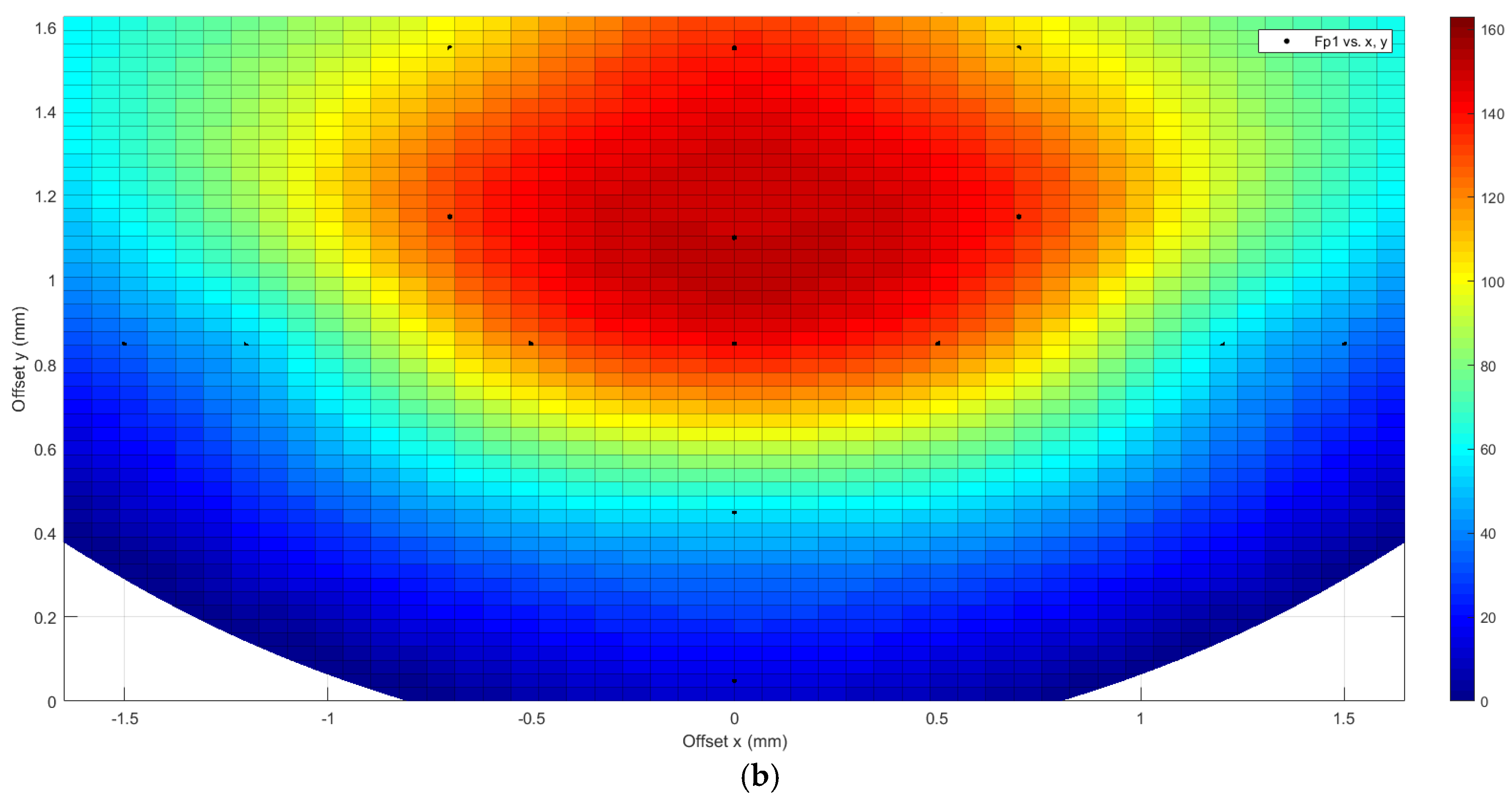
- Very low puncture resistance values were found in analysis number 5, in which the tip is placed near the center of the scale. This is due to the fact that at that point, the affected scale is more exposed, since it is less helped by the nearby scales, due to the degree of overlap used;
- Analysis number 9 is the only one in which the type 1 bio-inspired scale structure has a greater perforation resistance than the type 2 bio-inspired scale structure.
3.4. Flexural Test
3.4.1. Type 1 Bio-Inspired Scale Structure
3.4.2. Type 2 Bio-Inspired Scale Structure
4. Discussion
5. Conclusions
- Scale material;
- Substrate construction material;
- Geometric structure of the scale: dimensions, shape, and thickness;
- Distance between the various scales placed above the substrate;
- Types of reciprocal dispositions of the scales: with scales placed side by side, with overlapping scales, and with overlapping and staggered scales;
- The ratio between the surface area of the scale and the distance between their centers;
- The ratio between the area of the connection to the substrate and the area of the scale.
Future Work
Author Contributions
Funding
Institutional Review Board Statement
Data Availability Statement
Conflicts of Interest
References
- Yang, W.; Chen, I.H.; Gludovatz, B.; Zimmermann, E.A.; Ritchie, R.O.; Meyers, M.A. Natural flexible dermal armor. Adv. Mater. 2013, 25, 31–48. [Google Scholar] [CrossRef] [PubMed]
- Naleway, S.E.; Taylor, J.R.A.; Porter, M.M.; Meyers, M.A.; McKittrick, J. Structure and mechanical properties of selected protective systems in marine organisms. Mater. Sci. Eng. C 2016, 59, 1143–1167. [Google Scholar] [CrossRef]
- Porter, M.M.; Ravikumar, N.; Barthelat, F.; Martini, R. 3D-printing and mechanics of bio-inspired articulated and multi-material structures. J. Mech. Behav. Biomed. Mater. 2017, 73, 114–126. [Google Scholar] [CrossRef] [PubMed]
- Martini, R.; Balit, Y.; Barthelat, F. A comparative study of bio-inspired protective scales using 3D printing and mechanical testing. Acta Biomater. 2017, 55, 360–372. [Google Scholar] [CrossRef]
- Martini, R.; Barthelat, F. Stretch-and-release fabrication, testing and optimization of a flexible ceramic armor inspired from fish scales. Bioinspir. Biomim. 2016, 11, 066001. [Google Scholar] [CrossRef] [PubMed]
- Szewciw, L.; Zhu, D.; Barthelat, F. The nonlinear flexural response of a whole teleost fish: Contribution of scales and skin. J. Mech. Behav. Biomed. Mater. 2017, 76, 97–103. [Google Scholar] [CrossRef] [PubMed]
- Szewciw, L.; Barthelat, F. Mechanical properties of striped bass fish skin: Evidence of an exotendon function of the stratum compactum. J. Mech. Behav. Biomed. Mater. 2017, 73, 28–37. [Google Scholar] [CrossRef]
- Vernerey, F.J.; Musiket, K.; Barthelat, F. Mechanics of fish skin: A computational approach for bio-inspired flexible composites. Int. J. Solids Struct. 2014, 51, 274–283. [Google Scholar] [CrossRef]
- Wang, S.; Li, S.; Xu, T.; Bian, Y.; Miao, C.; Luo, C. A Comparative study of the mechanical properties of the bio-inspired overlapped scales fabricated by 3D printing. Extrem. Mech. Lett. 2023, 63, 102052. [Google Scholar] [CrossRef]
- Meyers, M.A.; Chen, P.Y.; Lopez, M.I.; Seki, Y.; Lin, A.Y.M. Biological materials: A materials science approach. J. Mech. Behav. Biomed. Mater. 2011, 4, 626–657. [Google Scholar] [CrossRef] [PubMed]
- Hossain, M.S.; Ebrahimi, H.; Ghosh, R. Fish scale inspired structures: A review of materials, manufacturing and models. Bioinspir. Biomim. 2022, 17, 61001. [Google Scholar] [CrossRef] [PubMed]
- Currey, J.D. The design of mineralised hard tissues for their mechanical functions. J. Exp. Biol. 1999, 202, 3285–3294. [Google Scholar] [CrossRef] [PubMed]
- Zhang, D.; Zhu, M.; Li, Z. Fish scales and their biomimetic applications. Front. Mater. 2021, 8, 649456. [Google Scholar]
- Martini, R.; Barthelat, F. Stability of hard plates on soft substrates and application to the design of bioinspired segmented armor. J. Mech. Phys. Solids 2016, 92, 195–209. [Google Scholar] [CrossRef]
- Chen, I.H.; Yang, W.; Meyers, M.A. Alligator osteoderms: Mechanical behavior and hierarchical structure. Mater. Sci. Eng. C 2014, 35, 441–448. [Google Scholar] [CrossRef]
- Chen, I.H.; Kiang, J.H.; Correa, V.; Lopez, M.I.; Chen, P.Y.; McKittrick, J.; Meyers, M.A. Armadillo armor: Mechanical testing and micro-structural evaluation. J. Mech. Behav. Biomed. Mater. 2011, 4, 713–722. [Google Scholar] [CrossRef] [PubMed]
- Wang, B.; Yang, W.; Sherman, V.R.; Meyers, M.A. Pangolin armor: Overlapping, structure, and mechanical properties of the keratinous scales. Acta Biomater. 2016, 41, 60–74. [Google Scholar] [CrossRef]
- Chang, Y.; Chen, P.Y. Hierarchical structure and mechanical properties of snake (naja atra) and turtle (ocadia sinensis) eggshells. Acta Biomater. 2016, 31, 33–49. [Google Scholar] [CrossRef] [PubMed]
- Yang, W.; Gludovatz, B.; Zimmermann, E.A.; Bale, H.A.; Ritchie, R.O.; Meyers, M.A. Structure and fracture resistance of alligator gar (atractosteus spatula) armored fish scales. Acta Biomater. 2013, 9, 5876–5889. [Google Scholar] [CrossRef] [PubMed]
- Quan, H.; Yang, W.; Lapeyriere, M.; Schaible, E.; Ritchie, R.O.; Meyers, M.A. Structure and mechanical adaptability of a modern elasmoid fish scale from the common carp. Matter 2020, 3, 842–863. [Google Scholar] [CrossRef]
- Ghods, S.; Murcia, S.; Ossa, E.A.; Arola, D. Designed for resistance to puncture: The dynamic response of fish scales. J. Mech. Behav. Biomed. Mater. 2019, 90, 451–459. [Google Scholar] [CrossRef]
- Porter, M.M.; Novitskaya, E.; Castro-Ceseña, A.B.; Meyers, M.A.; McKittrick, J. Highly deformable bones: Unusual deformation mechanisms of seahorse armor. Acta Biomater. 2013, 9, 6763–6770. [Google Scholar] [CrossRef] [PubMed]
- Besseau, L.; Bouligand, Y. The twisted collagen network of the box-fish scutes. Tissue Cell 1998, 30, 251–260. [Google Scholar] [CrossRef] [PubMed]
- Rudykh, S.; Ortiz, C.; Boyce, M.C. Flexibility and protection by design: Imbricated hybrid microstructures of bio-inspired armor. Soft Matter 2015, 11, 2547–2554. [Google Scholar] [CrossRef] [PubMed]
- Barthelat, F. Science and engineering of natural materials: Merging structure and materials. J. Mech. Behav. Biomed. Mater. 2013, 19, 1–2. [Google Scholar] [CrossRef]
- Rawat, P.; Zhu, D.; Rahman, M.Z.; Barthelat, F. Structural and mechanical properties of fish scales for the bio-inspired design of flexible body armors: A review. Acta Biomater. 2021, 121, 41–67. [Google Scholar] [CrossRef]
- Ghosh, R.; Ebrahimi, H.; Vaziri, A. Contact kinematics of biomimetic scales. Appl. Phys. Lett. 2014, 105, 233701. [Google Scholar] [CrossRef]
- Porter, M.M.; Adriaens, D.; Hatton, R.L.; Meyers, M.A.; McKittrick, J. Why the seahorse tail is square. Science 2015, 349, aaa6683. [Google Scholar] [CrossRef]
- Wen, L.; Weaver, J.C.; Lauder, G.V. Biomimetic shark skin: Design, fabrication and hydrodynamic function. J. Exp. Biol. 2014, 217, 1656–1666. [Google Scholar] [CrossRef] [PubMed]
- Sherman, V.R.; Quan, H.; Yang, W.; Ritchie, R.O.; Meyers, M.A. A comparative study of piscine defense: The scales of arapaima gigas, latimeria chalumnae and atractosteus spatula. J. Mech. Behav. Biomed. Mater. 2017, 73, 1–16. [Google Scholar] [CrossRef]
- Miranda, P.; Pajares, A.; Meyers, M.A. Bioinspired composite segmented armour: Numerical simulations. J. Mater. Res. Technol. 2019, 8, 1274–1287. [Google Scholar] [CrossRef]
- Shafiei, A.; Pro, J.W.; Martini, R.; Barthelat, F. The very hard and the very soft: Modeling bio-inspired scaled skins using the discrete element method. J. Mech. Phys. Solids 2021, 146, 104176. [Google Scholar] [CrossRef]
- Yang, W.; Naleway, S.E.; Porter, M.M.; Meyers, M.A.; McKittrick, J. The armored carapace of the boxfish. Acta Biomater. 2015, 23, 1–10. [Google Scholar] [CrossRef] [PubMed]
- Ghosh, R.; Ebrahimi, H.; Vaziri, A. Frictional effects in biomimetic scales engagement. EPL 2016, 113, 34003. [Google Scholar] [CrossRef]
- Dharmavaram, S.; Ebrahimi, H.; Ghosh, R. Coupled bend–twist mechanics of biomimetic scale substrate. J. Mech. Phys. Solids 2022, 159, 104711. [Google Scholar] [CrossRef]
- Ortiz, C.; Boyce, M.C. Bioinspired design of flexible armor based on chiton scales. Nat. Commun. 2019, 10, 13215. [Google Scholar]
- Wang, X.; Liu, J.; Li, J.; Ma, X. Modeling bioinspired fish scale designs via a geometric and computational approach. Materials 2021, 14, 5378. [Google Scholar]
- Meyers, M.A.; Lin, A.Y.M.; Chen, I.H.; Seki, Y.; Lopez, M.I. Microstructure and mechanical properties of fish scales from Megalops atlanticus. J. Mech. Behav. Biomed. Mater. 2013, 20, 1–14. [Google Scholar]
- Dura, H.B.; Hazell, P.J.; Wang, H.; Wang, J. Energy absorption of composite 3D-printed fish scale inspired protective structures subjected to low-velocity impact. Compos. Sci. Technol. 2024, 255, 110725. [Google Scholar] [CrossRef]
- Dura, B.; Hazell, P.J.; Wang, H.; Escobedo-Diaz, J.P. Effect of scale morphology on the mechanical response of bio-inspired fish-scale-based protective structures. Compos. Part A Appl. Sci. Manuf. 2023, 174, 107720. [Google Scholar] [CrossRef]
- Tian, X.; Chen, L.; Zhou, J.; Wang, E.; Wang, M.; Jakubovics, N.; Li, J.; Song, K.; Lau, K.T.; Koepfli, K.-P.; et al. Pangolin scales as adaptations for innate immunity against pathogens. BMC Biol. 2024, 22, 234. [Google Scholar] [CrossRef]


| Number of Analyses | Point of Action of the Tip with Respect to the Center of the Scale | Critical Drilling Force Fp (N) | ||
|---|---|---|---|---|
| Offset X (mm) | Offset Y (mm) | Structure Bio 1 | Structure Bio 2 | |
| 1 | 0 | 0.85 | 144 N | 156 N |
| 2 | −1.2 | 0.85 | 56 N | 82 N |
| 3 | 0 | 1.55 | 136 N | 158 N |
| 4 | 0 | 0.45 | 60 N | 70 N |
| 5 | 0 | 0.05 | 16 N | 23 N |
| 6 | −1.5 | 0.85 | 39 N | 70 N |
| 7 | −0.5 | 0.85 | 129 N | 142 N |
| 8 | −0.7 | 1.55 | 105 N | 131 N |
| 9 | −0.7 | 1.15 | 134 N | 130 N |
Disclaimer/Publisher’s Note: The statements, opinions and data contained in all publications are solely those of the individual author(s) and contributor(s) and not of MDPI and/or the editor(s). MDPI and/or the editor(s) disclaim responsibility for any injury to people or property resulting from any ideas, methods, instructions or products referred to in the content. |
© 2025 by the authors. Licensee MDPI, Basel, Switzerland. This article is an open access article distributed under the terms and conditions of the Creative Commons Attribution (CC BY) license (https://creativecommons.org/licenses/by/4.0/).
Share and Cite
Pantano, A.; Baiamonte, V. Mechanics of Bio-Inspired Protective Scales. Biomimetics 2025, 10, 75. https://doi.org/10.3390/biomimetics10020075
Pantano A, Baiamonte V. Mechanics of Bio-Inspired Protective Scales. Biomimetics. 2025; 10(2):75. https://doi.org/10.3390/biomimetics10020075
Chicago/Turabian StylePantano, Antonio, and Vincenzo Baiamonte. 2025. "Mechanics of Bio-Inspired Protective Scales" Biomimetics 10, no. 2: 75. https://doi.org/10.3390/biomimetics10020075
APA StylePantano, A., & Baiamonte, V. (2025). Mechanics of Bio-Inspired Protective Scales. Biomimetics, 10(2), 75. https://doi.org/10.3390/biomimetics10020075