

A Numerical Study of Flow Past a Wall-Mounted Dolphin Dorsal Fin at Low Reynolds Numbers


Abstract
1. Introduction
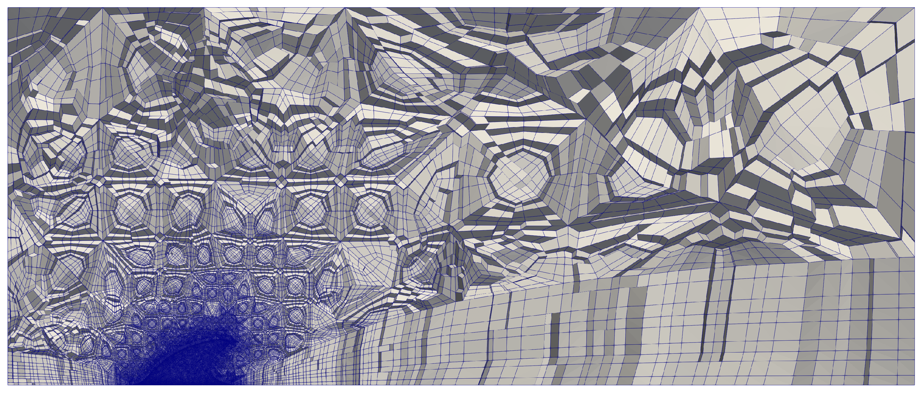
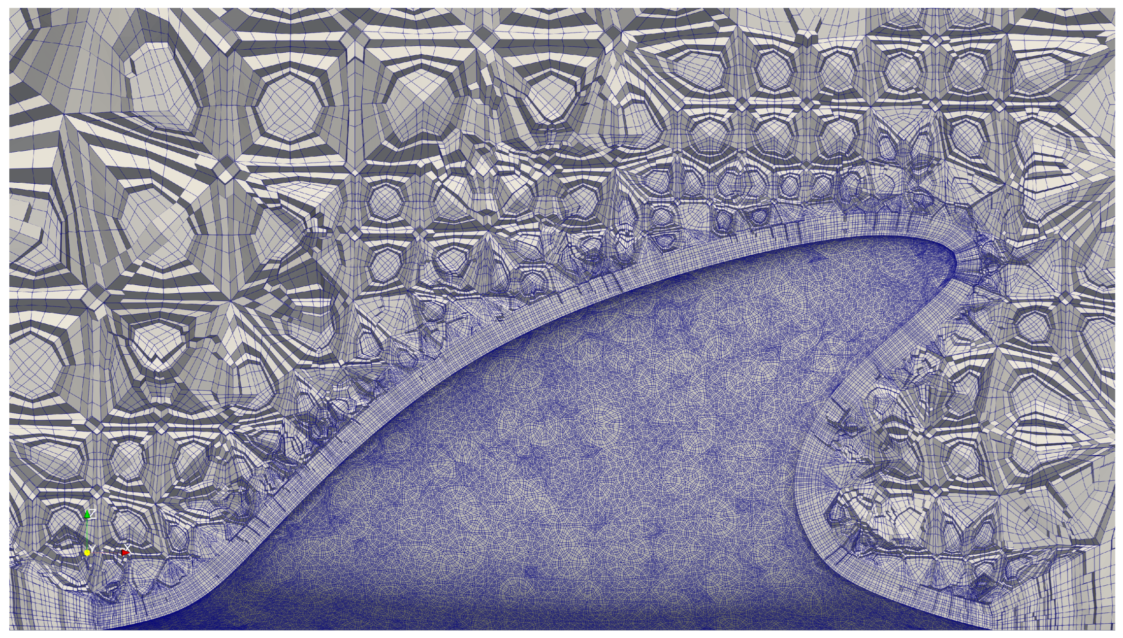
2. Computational Methods
2.1. NEK5000
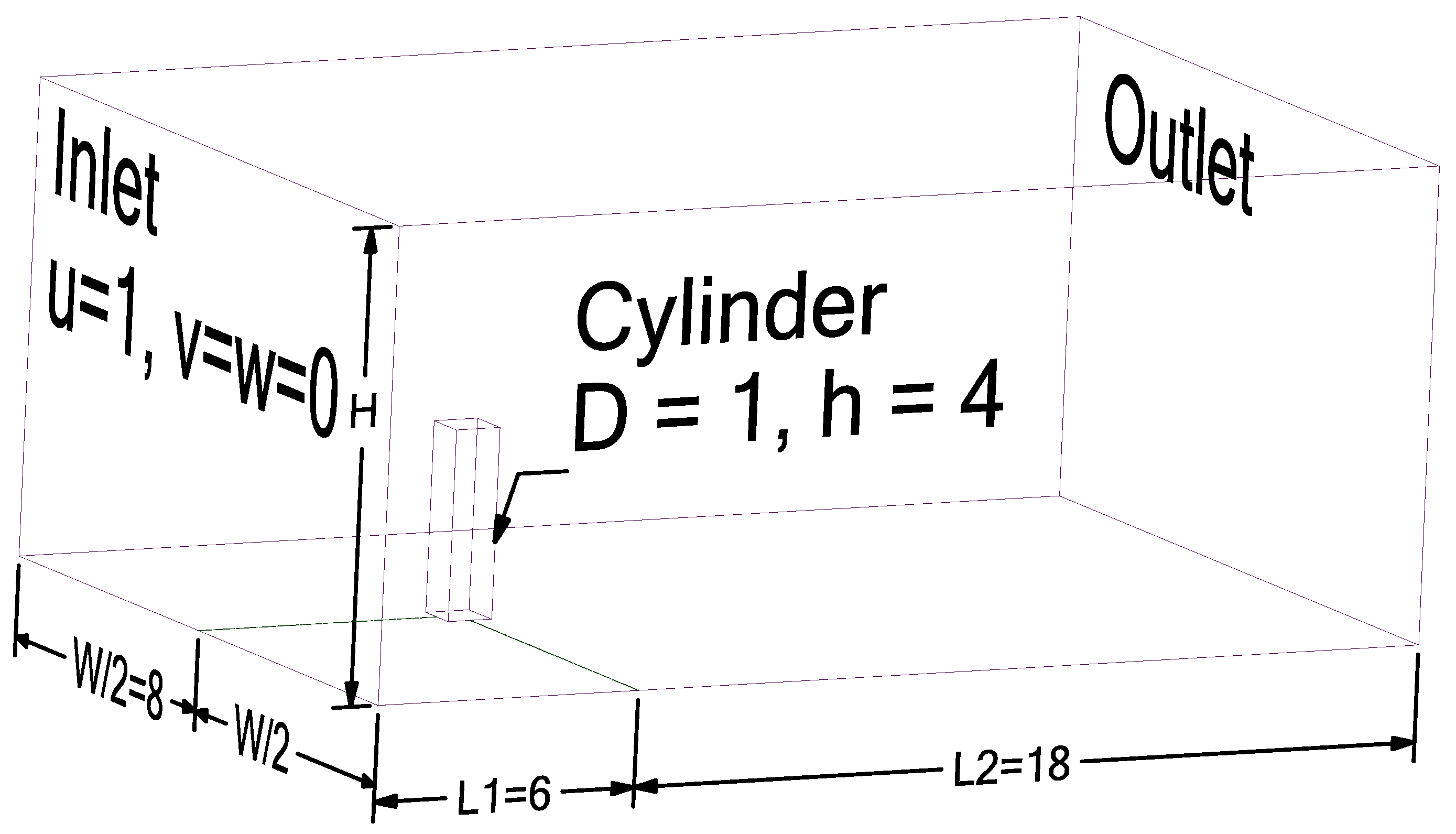
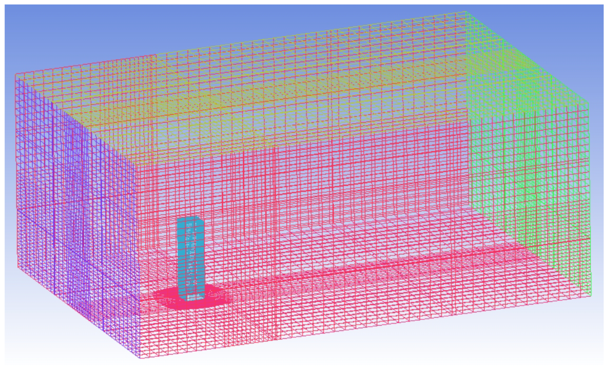
2.2. Problem Setup
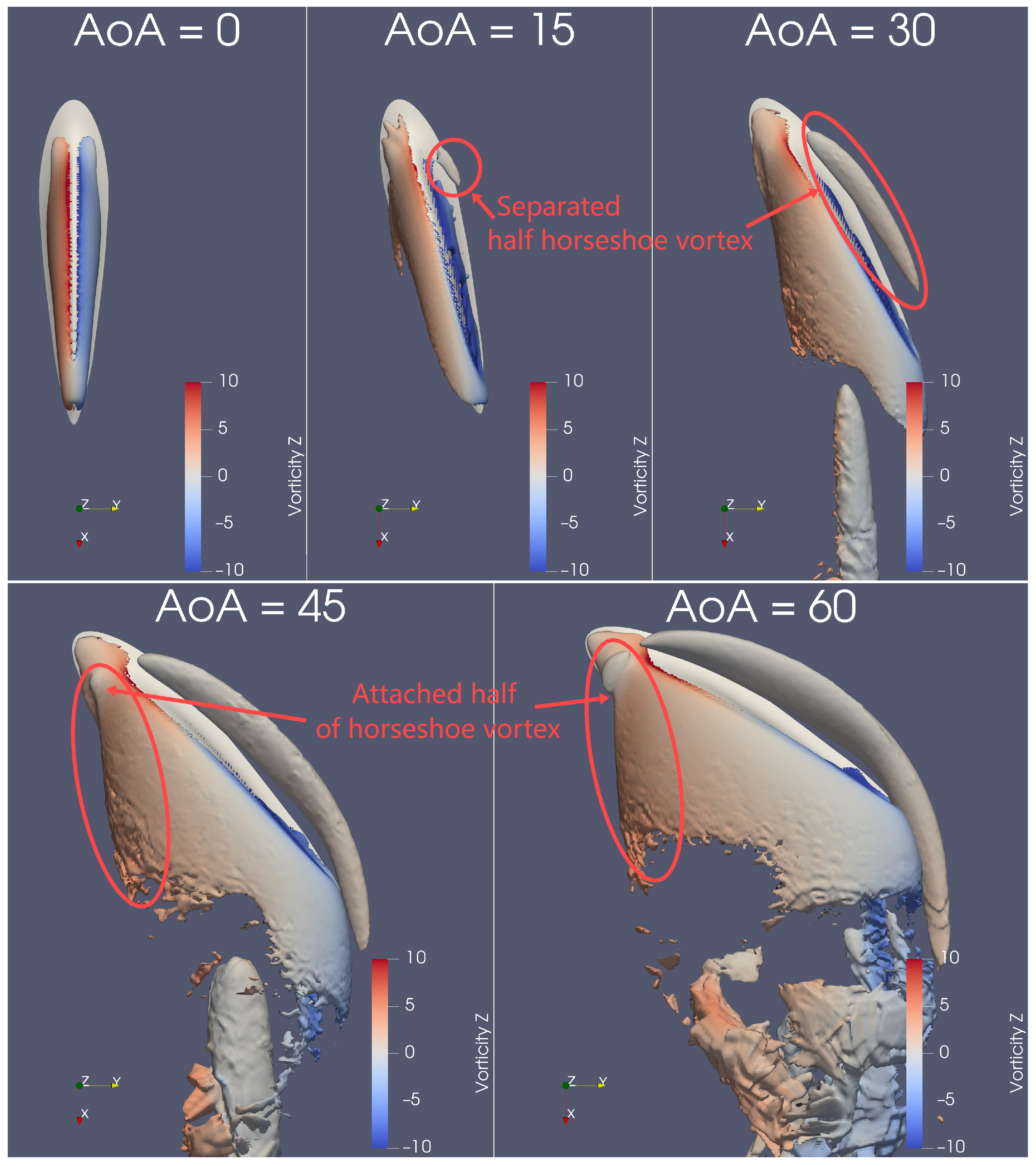
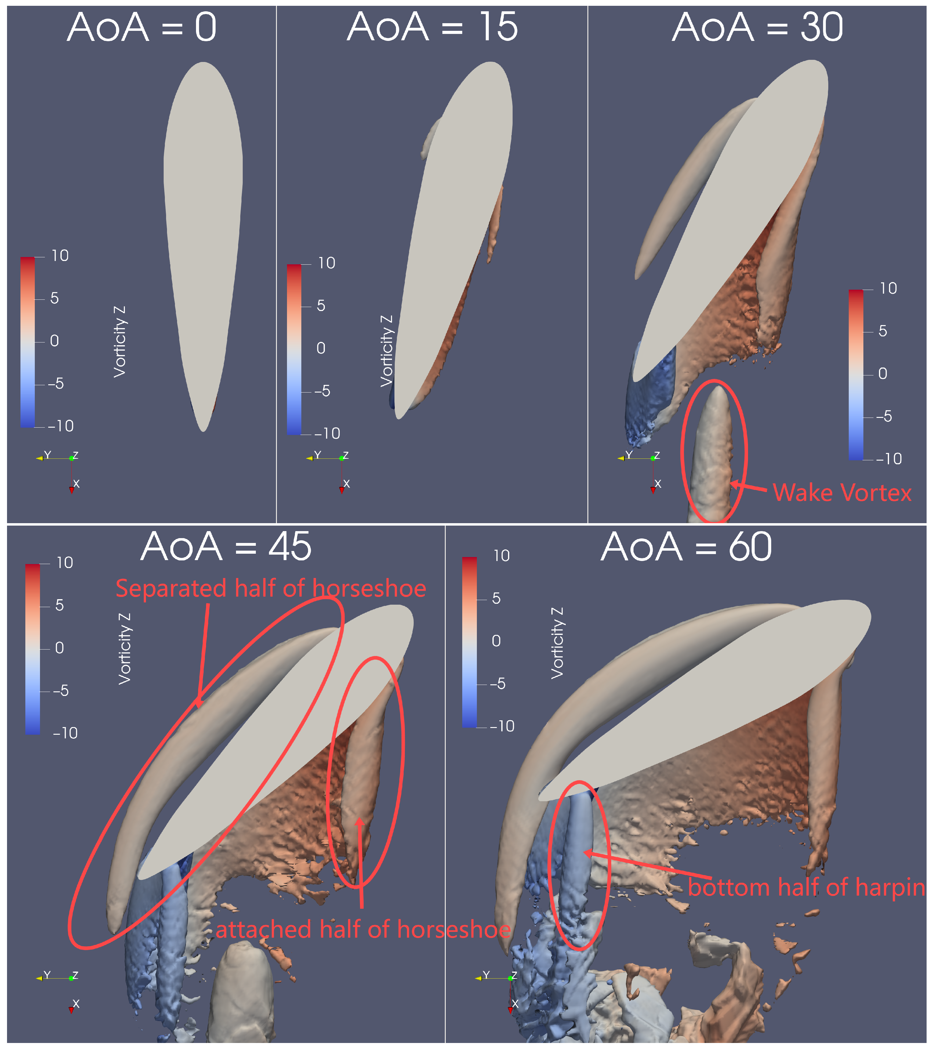
3. Discussion of Numerical Results
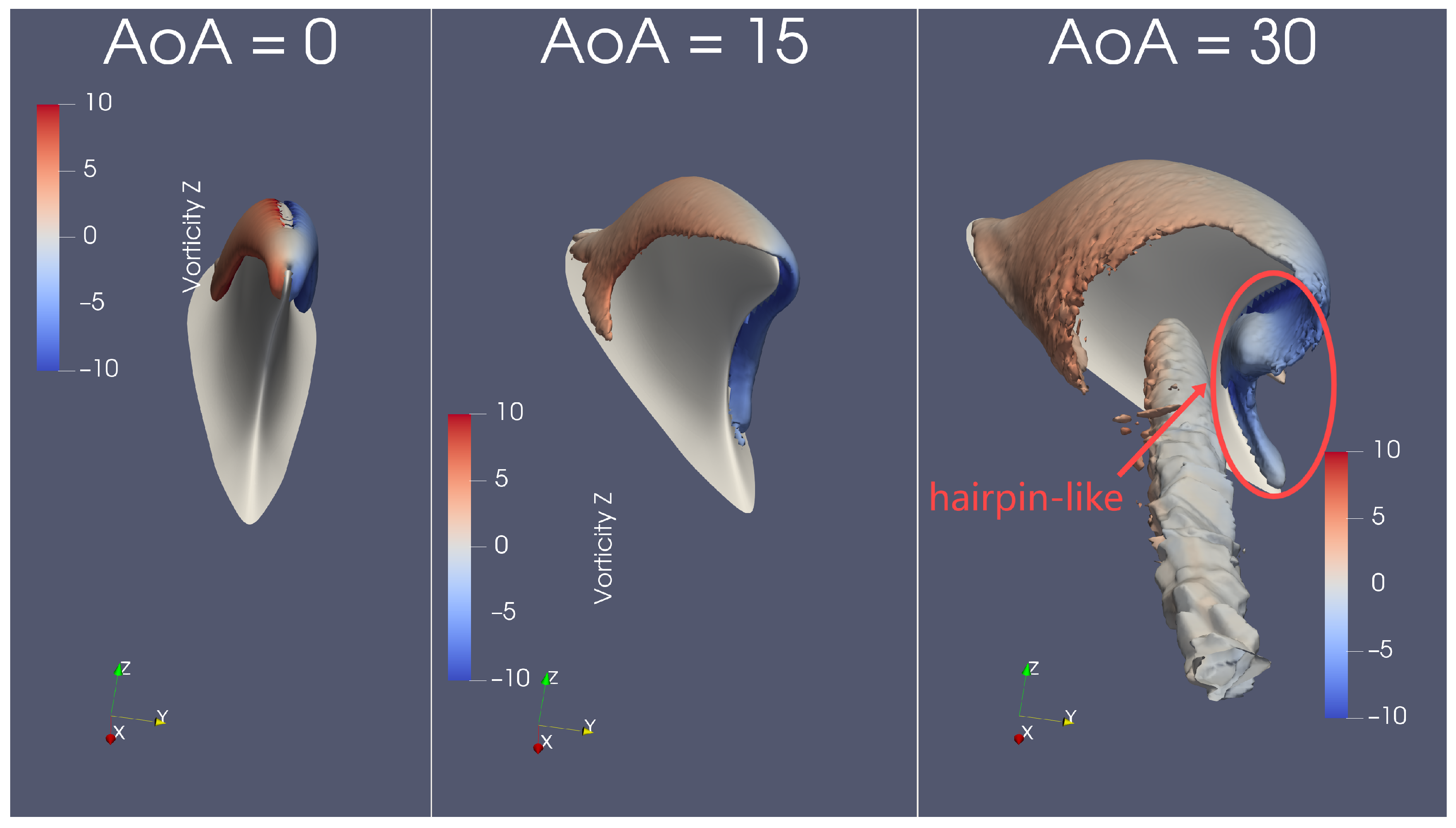
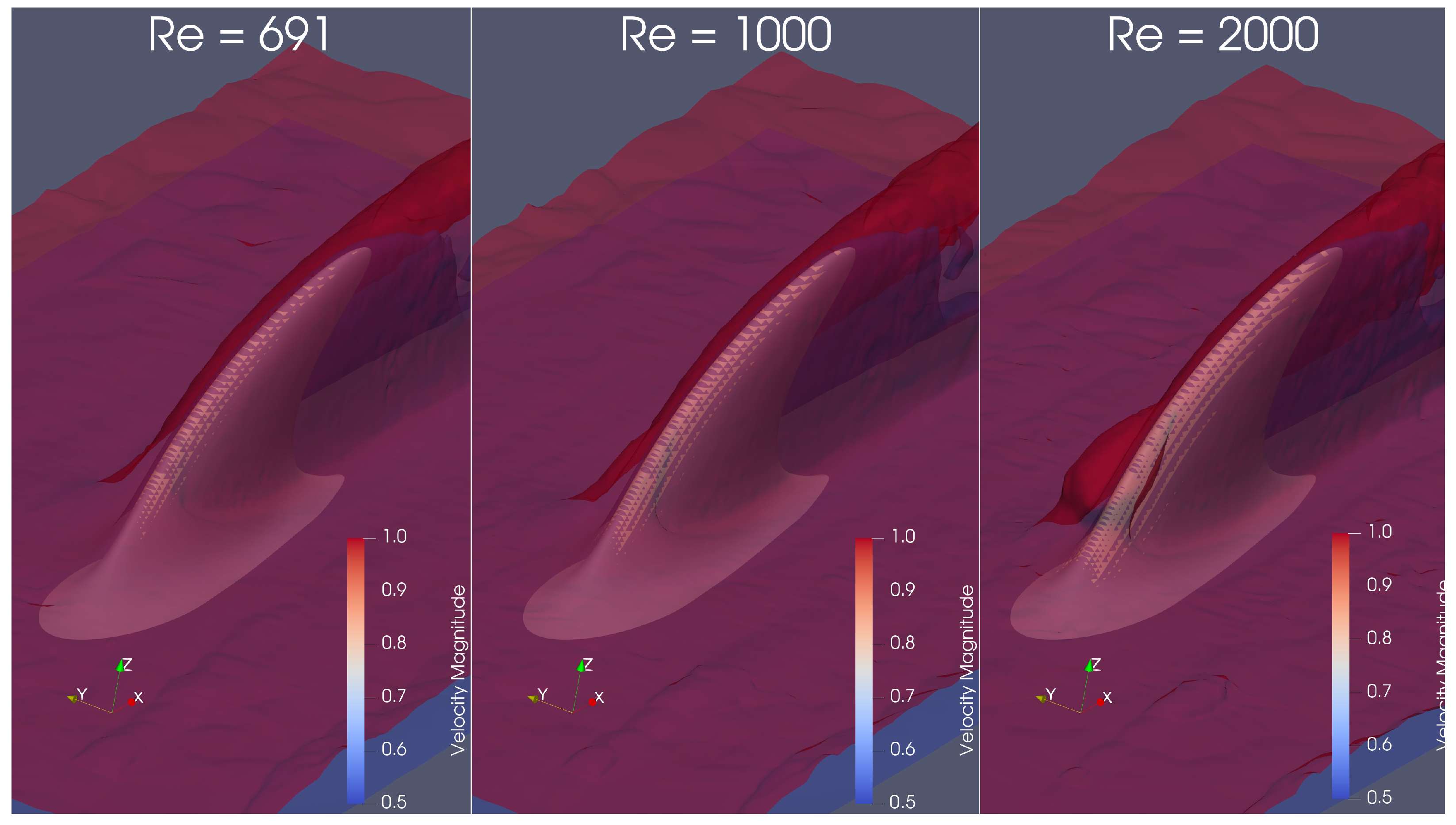
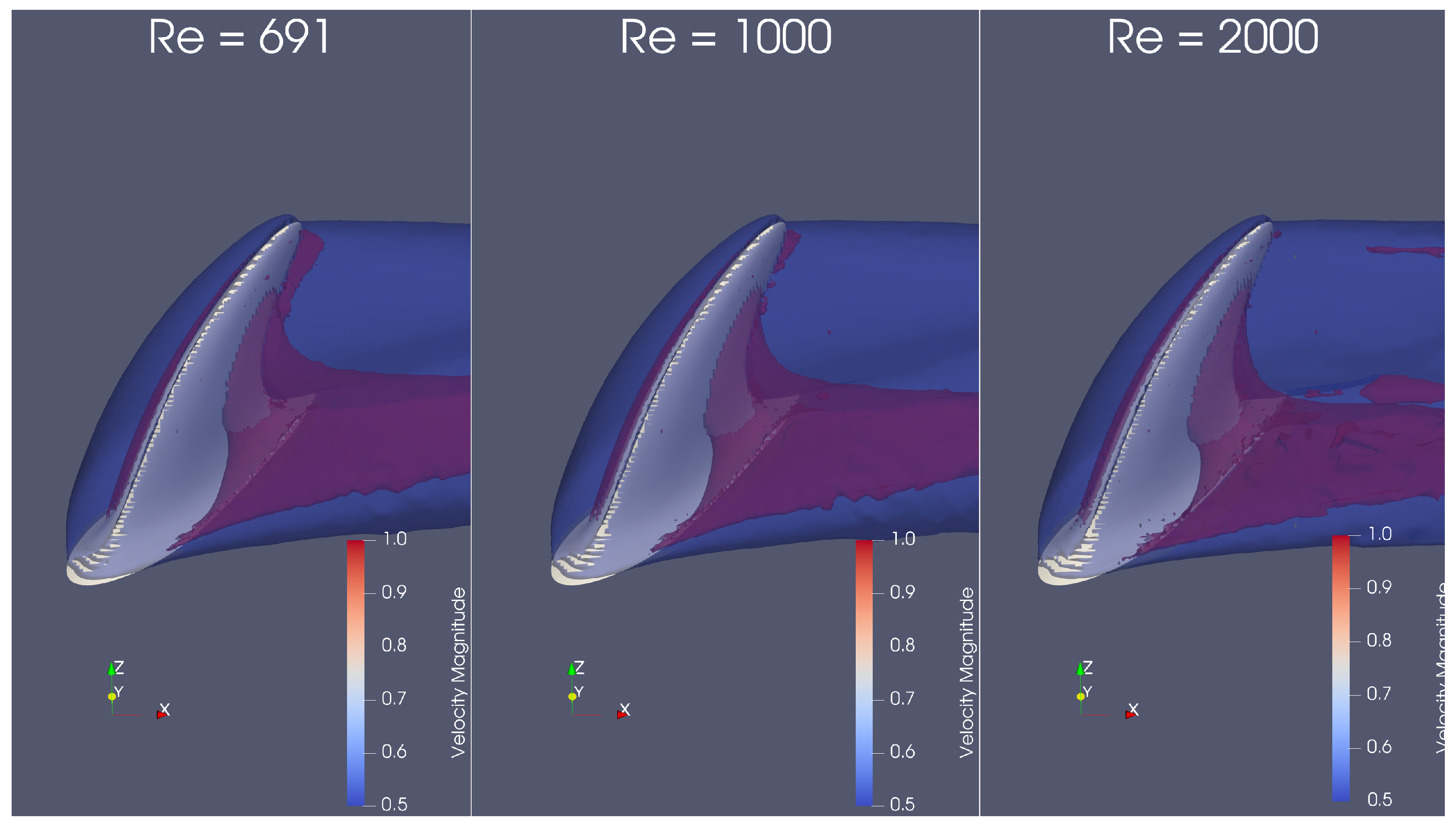
Flow Structure by Q-Criterion Isosurface
4. Conclusions
Author Contributions
Funding
Data Availability Statement
Conflicts of Interest
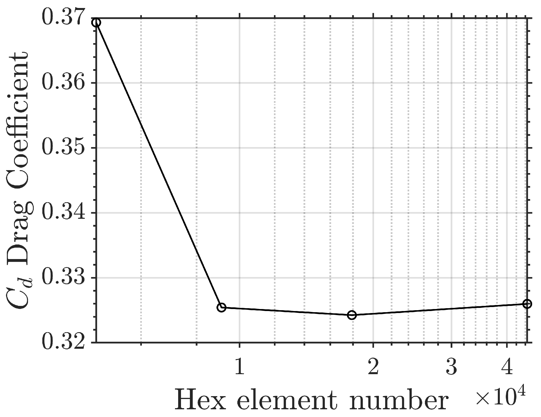
Appendix A. Validation

| Name | Grid Resolution | Element Number | Time Step | Mean Drag Coefficient, Re = 250 | |
|---|---|---|---|---|---|
| M1 | a | 1.81 b | c | 0.00625 | 1.264 |
| M2 | 2.44 | 0.00500 | 1.243 | ||
| M3 | 3.24 | 0.00417 | 1.234 | ||
| M4 | 4.23 | 0.00300 | 1.230 | ||
| Ming’s Level-1 | 39.8 | 0.002 | 1.186 | ||
| Ming’s Level-2 | 61.8 | 0.001 | 1.208 | ||
| Ming’s Level-3 | 82.4 | 0.0008 | 1.213 | ||
| Saha’s Coarse Level | 16.6 | 0.002 | 1.19 | ||
| Saha’s Middle Level | 28.9 | 0.002 | 1.23 | ||
| Saha’s Refined Level | 40.4 | 0.002 | 1.23 |
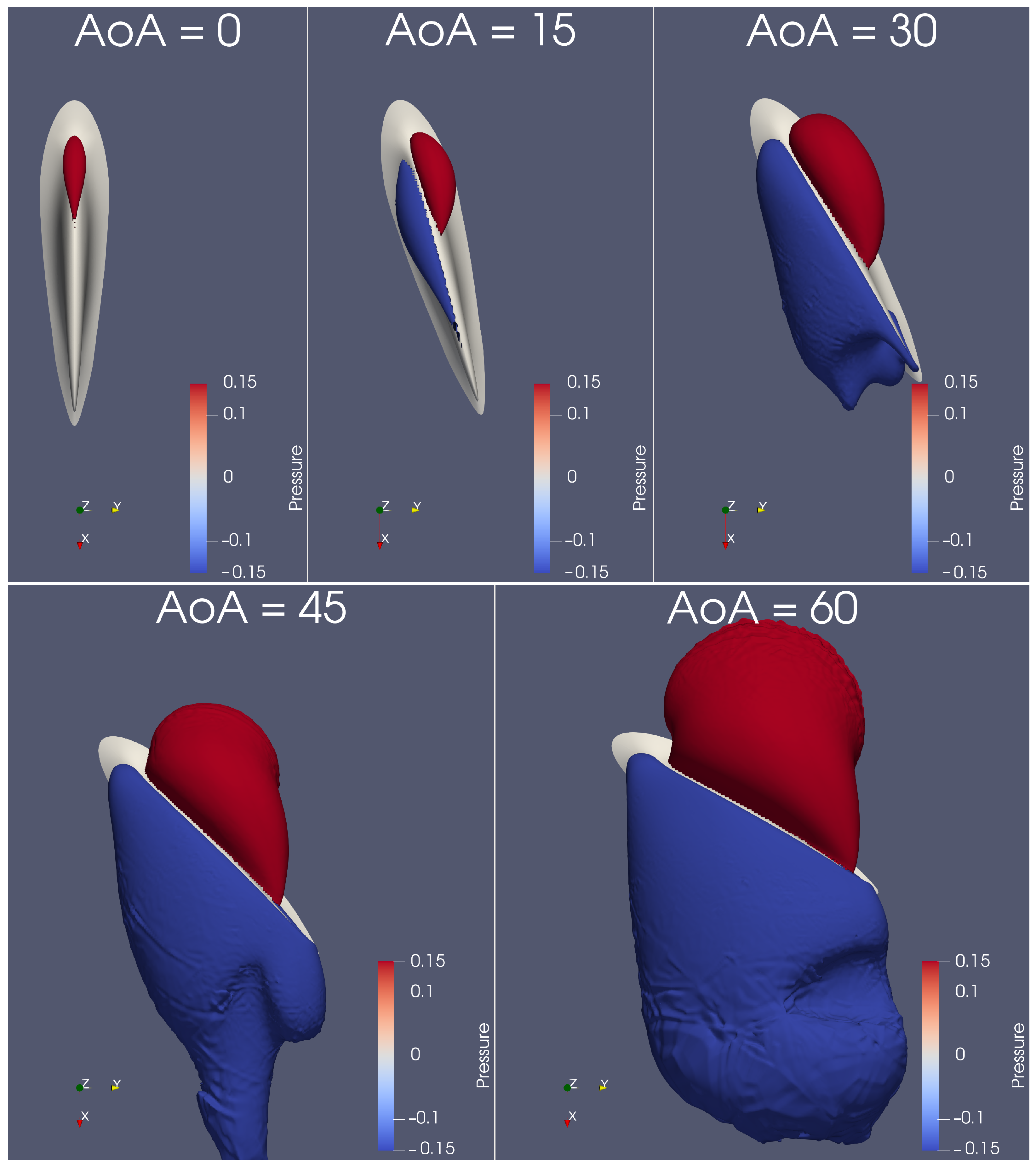
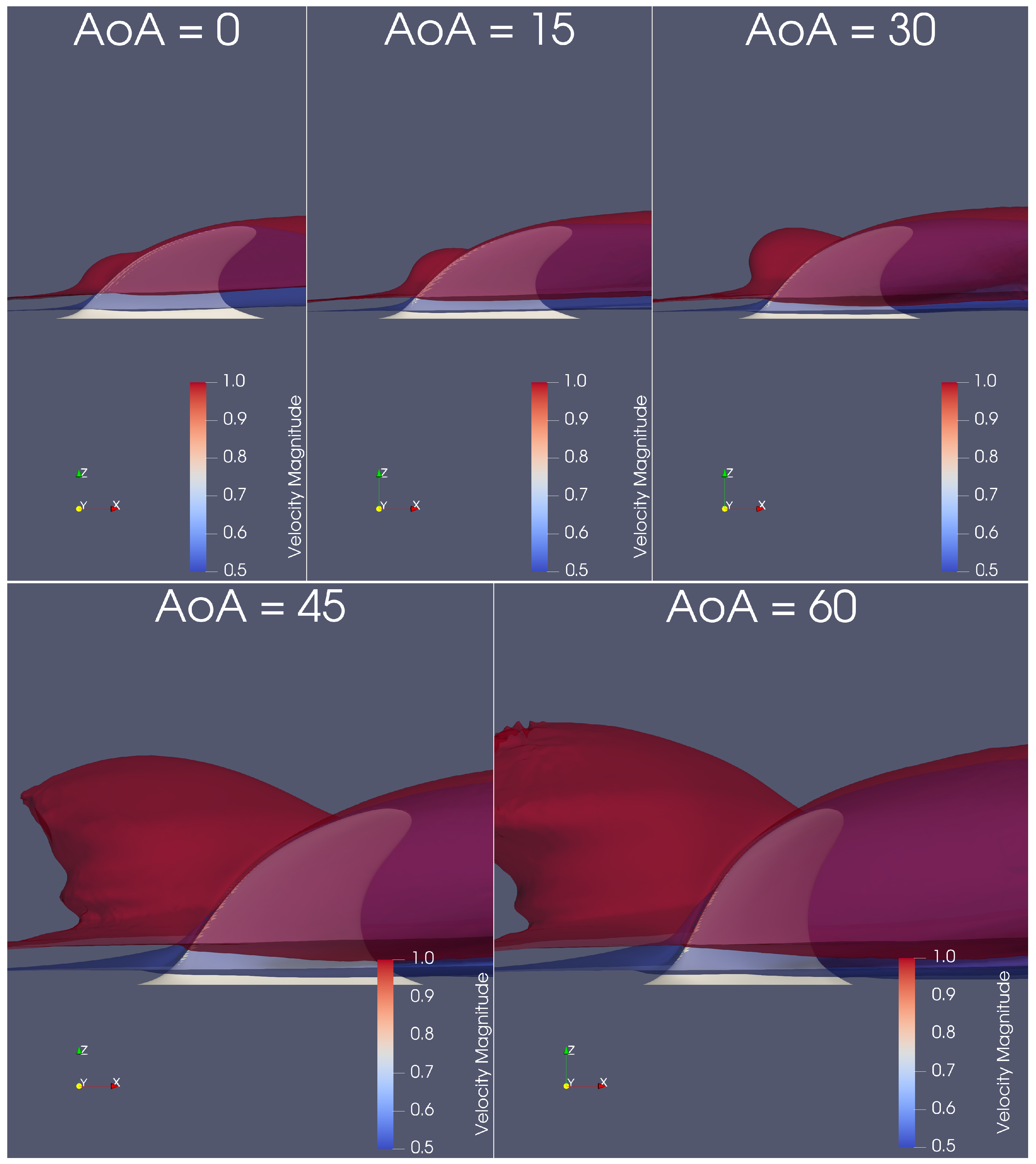
Appendix A.1. Pressure and Velocity Distribution
Appendix B. Additional Data
References
- Shoele, K.; Zhu, Q. Drafting mechanisms between a dolphin mother and calf. J. Theor. Biol. 2015, 382, 363–377. [Google Scholar] [CrossRef] [PubMed]
- Weihs, D. The Hydrodynamics of Dolphin Drafting. J. Biol. 2004, 3, 8. [Google Scholar] [CrossRef] [PubMed]
- Yu, J.; Wang, T.; Chen, D.; Meng, Y. Quantifying the Leaping Motion Using a Self-Propelled Bionic Robotic Dolphin Platform. Biomimetics 2023, 8, 21. [Google Scholar] [CrossRef] [PubMed]
- Fish, F.E.; Rohr, J. Review of Dolphin Hydrodynamics and Review of Dolphin Hydrodynamics; Technical Report; Space and Naval Warfare Systems Command: San Diego, CA, USA, 1999; Available online: https://apps.dtic.mil/sti/citations/ADA369158 (accessed on 7 September 2024).
- Wang, J.; Pavlov, V.; Lou, Z.; Dong, H. Computational investigation of thrust production of a dolphin at various swimming speeds. In Proceedings of the American Society of Mechanical Engineers, Fluids Engineering Division (Publication) FEDSM, Virtual, Online, 10–12 August 2021; Volume 1. [Google Scholar] [CrossRef]
- Wang, J.; Wu, Z.; Tan, M.; Yu, J. Controlling the depth of a gliding robotic dolphin using dual motion control modes. Sci. China Inf. Sci. 2020, 63, 192206. [Google Scholar] [CrossRef]
- Han, P.; Wang, J.; Fish, F.E.; Dong, H. Kinematics and Hydrodynamics of a Dolphin in Forward Swimming. In Proceedings of the AIAA AVIATION 2020 FORUM (2020), Virtual Event, 15–19 June 2020; p. 3015. [Google Scholar] [CrossRef]
- Pavlov, V.; Vincent, C.; Mikkelsen, B.; Lebeau, J.; Ridoux, V.; Siebert, U. Form, function, and divergence of a generic fin shape in small cetaceans. PLoS ONE 2021, 16, e0255464. [Google Scholar] [CrossRef]
- Fish, F.E.; Howle, L.E.; Murray, M.M. Hydrodynamic flow control in marine mammals. Integr. Comp. Biol. 2008, 48, 788–800. [Google Scholar] [CrossRef]
- Niño-Torres, C.A.; Olvera-Gómez, J.A.; Ramos, E.; Castelblanco-Martínez, D.N.; Blanco-Parra, M.P.; May-Collado, L.J.; Sellares, R. High similarities in dorsal fin ratios of common bottlenose dolphins (Tursiops truncatus) in the Caribbean Sea. Mar. Mammal Sci. 2023, 39, 533–552. [Google Scholar] [CrossRef]
- Li, S.; Wu, Z.; Wang, J.; Qiu, C.; Tan, M.; Yu, J. Robust Depth and Heading Control System for a Novel Robotic Dolphin With Multiple Control Surfaces. IEEE Trans. Autom. Sci. Eng. 2024, 1–16. [Google Scholar] [CrossRef]
- Bashtani, I.; Esfahani, J.A.; Kim, K.C. Hybrid CFD-ANN approach for evaluation of bio-inspired dolphins dorsal fin turbulators of heat exchanger in turbulent flow. Appl. Therm. Eng. 2023, 219, 119422. [Google Scholar] [CrossRef]
- Rahmani, M.; Jafari Gavzan, I.; Dehghan Manshadi, M. Experimental investigation of the effect of sail geometry on the flow around the SUBOFF submarine model inspired by the dolphin’s dorsal fin. Ships Offshore Struct. 2024, 19, 769–778. [Google Scholar] [CrossRef]
- Guo, J.; Zhang, W.; Han, P.; Fish, F.E.; Dong, H. Thrust generation and propulsive efficiency in dolphin-like swimming propulsion. Bioinspir. Biomim. 2023, 18, 056001. [Google Scholar] [CrossRef] [PubMed]
- Bergmann, M. Numerical modeling of a self-propelled dolphin jump out of water. Bioinspir. Biomim. 2022, 17, 065010. [Google Scholar] [CrossRef] [PubMed]
- Skrovan, R.C.; Williams, T.M.; Berry, P.S.; Moore, P.W.; Davis, R.W. The diving physiology of bottlenose dolphins (Tursiops truncatus): II. Biomechanics and changes in buoyancy at depth. J. Exp. Biol. 1999, 202, 2749–2761. [Google Scholar] [CrossRef]
- Wu, Z.; Yu, J.; Yuan, J.; Tan, M. Towards a gliding robotic dolphin: Design, modeling, and experiments. IEEE/ASME Trans. Mechatron. 2019, 24, 260–270. [Google Scholar] [CrossRef]
- Zhang, Y.; Wu, Z.; Wang, J.; Tan, M. Design and Analysis of a Bionic Gliding Robotic Dolphin. Biomimetics 2023, 8, 151. [Google Scholar] [CrossRef]
- Pavlov, V.V.; Rashad, A.M. A non-invasive dolphin telemetry tag: Computer design and numerical flow simulation. Mar. Mammal Sci. 2012, 28, E16–E27. [Google Scholar] [CrossRef]
- Okamura, T.; Akune, Y.; Mori, T.; Morisaka, T.; Otomo, W.; Wakabayashi, I.; Watanabe, S.; Yoda, K. Contribution of flippers and dorsal fins to the lateral/directional inherent stability during straight-line swimming in small cetaceans. J. Zool. 2021, 315, 165–174. [Google Scholar] [CrossRef]
- Tanaka, H.; Li, G.; Uchida, Y.; Nakamura, M.; Ikeda, T.; Liu, H. Measurement of time-varying kinematics of a dolphin in burst accelerating swimming. PLoS ONE 2019, 14, e0210860. [Google Scholar] [CrossRef]
- Noren, S.R.; Biedenbach, G.; Redfern, J.V.; Edwards, E.F. Hitching a ride: The formation locomotion strategy of dolphin calves. Funct. Ecol. 2008, 22, 278–283. [Google Scholar] [CrossRef]
- Tawade, J.V.; Biradar, M.M.; Benal, S.S. A new approach of MHD flows for UCM fluid over a permeable moving plate with space and temperature dependent internal heat generation/absorption. AIP Conf. Proc. 2020, 2236, 060002. [Google Scholar] [CrossRef]
- Zhong, Q.; Dong, H.; Quinn, D.B. How dorsal fin sharpness affects swimming speed and economy. J. Fluid Mech. 2019, 878, 370–385. [Google Scholar] [CrossRef]
- Fischer, P.; Lottes, J.; Tufo, H. Nek5000; Technical Report; Argonne National Laboratory (ANL): Argonne, IL, USA, 2007. [Google Scholar]
- Quartapelle, L. Numerical Solution of the Incompressible Navier-Stokes Equations; Birkhäuser: Basel, Switzerland, 2012; International Series of Numerical Mathematics; Volume 113. [Google Scholar]
- Abouhussein, A.; Peet, Y.T. Computational framework for efficient high-fidelity optimization of bio-inspired propulsion and its application to accelerating swimmers. J. Comput. Phys. 2023, 482, 112038. [Google Scholar] [CrossRef]
- Patera, A.T. A spectral element method for fluid dynamics: Laminar flow in a channel expansion. J. Comput. Phys. 1984, 54, 468–488. [Google Scholar] [CrossRef]
- Karniadakis, G.; Sherwin, S. Spectral/hp Element Methods for Computational Fluid Dynamics; Oxford University Press: Cary, NC, USA, 2007. [Google Scholar] [CrossRef]
- Fischer, P.F. Implementation Considerations for the OIFS/Characteristics Approach to Convection Problems; Argonne National Laboratory: Argonne, IL, USA, 2003. [Google Scholar]
- Rezaeiravesh, S.; Jansson, N.; Peplinski, A.; Vincent, J.; Schlatter, P. Nek5000 Theory, Implementation and Optimization. KTH, FLOW-SESE Course. 2021. Available online: https://www.mech.kth.se/~pschlatt/Nek5000_2021.pdf (accessed on 7 September 2024).
- Tufo, H.M.; Fischer, P.F. Fast Parallel Direct Solvers for Coarse Grid Problems. J. Parallel Distrib. Comput. 2001, 61, 151–177. [Google Scholar] [CrossRef]
- Saha, A.K. Unsteady flow past a finite square cylinder mounted on a wall at low Reynolds number. Comput. Fluids 2013, 88, 599–615. [Google Scholar] [CrossRef]
- Zhang, D.; Cheng, L.; An, H.; Zhao, M. Direct numerical simulation of flow around a surface-mounted finite square cylinder at low Reynolds numbers. Phys. Fluids 2017, 29, 045101. [Google Scholar] [CrossRef]
- Rastan, M.R.; Sohankar, A.; Alam, M.M. Low-Reynolds-number flow around a wall-mounted square cylinder: Flow structures and onset of vortex shedding. Phys. Fluids 2017, 29, 103601. [Google Scholar] [CrossRef]
- Martínez-Sánchez, Á.; López, E.; Le Clainche, S.; Lozano-Durán, A.; Srivastava, A.; Vinuesa, R. Causality analysis of large-scale structures in the flow around a wall-mounted square cylinder. J. Fluid Mech. 2023, 967. [Google Scholar] [CrossRef]


Disclaimer/Publisher’s Note: The statements, opinions and data contained in all publications are solely those of the individual author(s) and contributor(s) and not of MDPI and/or the editor(s). MDPI and/or the editor(s) disclaim responsibility for any injury to people or property resulting from any ideas, methods, instructions or products referred to in the content. |
© 2024 by the authors. Licensee MDPI, Basel, Switzerland. This article is an open access article distributed under the terms and conditions of the Creative Commons Attribution (CC BY) license (https://creativecommons.org/licenses/by/4.0/).
Share and Cite
Lin, Z.; Gao, A.; Zhang, Y. A Numerical Study of Flow Past a Wall-Mounted Dolphin Dorsal Fin at Low Reynolds Numbers. Biomimetics 2024, 9, 682. https://doi.org/10.3390/biomimetics9110682
Lin Z, Gao A, Zhang Y. A Numerical Study of Flow Past a Wall-Mounted Dolphin Dorsal Fin at Low Reynolds Numbers. Biomimetics. 2024; 9(11):682. https://doi.org/10.3390/biomimetics9110682
Chicago/Turabian StyleLin, Zhonglu, Ankang Gao, and Yu Zhang. 2024. "A Numerical Study of Flow Past a Wall-Mounted Dolphin Dorsal Fin at Low Reynolds Numbers" Biomimetics 9, no. 11: 682. https://doi.org/10.3390/biomimetics9110682
APA StyleLin, Z., Gao, A., & Zhang, Y. (2024). A Numerical Study of Flow Past a Wall-Mounted Dolphin Dorsal Fin at Low Reynolds Numbers. Biomimetics, 9(11), 682. https://doi.org/10.3390/biomimetics9110682