

Bioarchitectonic Nanophotonics by Replication and Systolic Miniaturization of Natural Forms


Abstract
1. Introduction
2. Materials and Methods
2.1. Instrumentation
2.2. Elements of Insect Organs
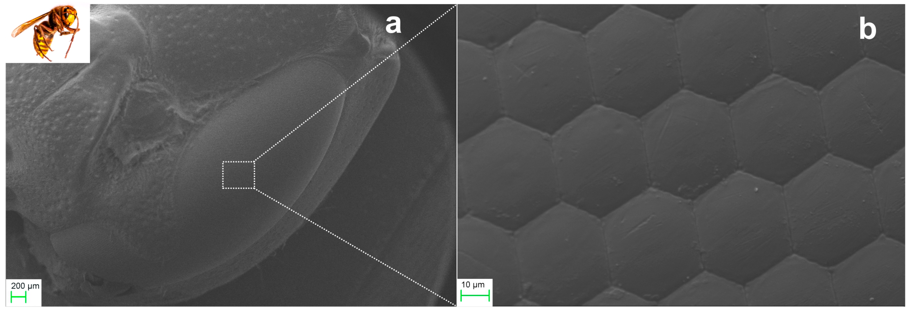
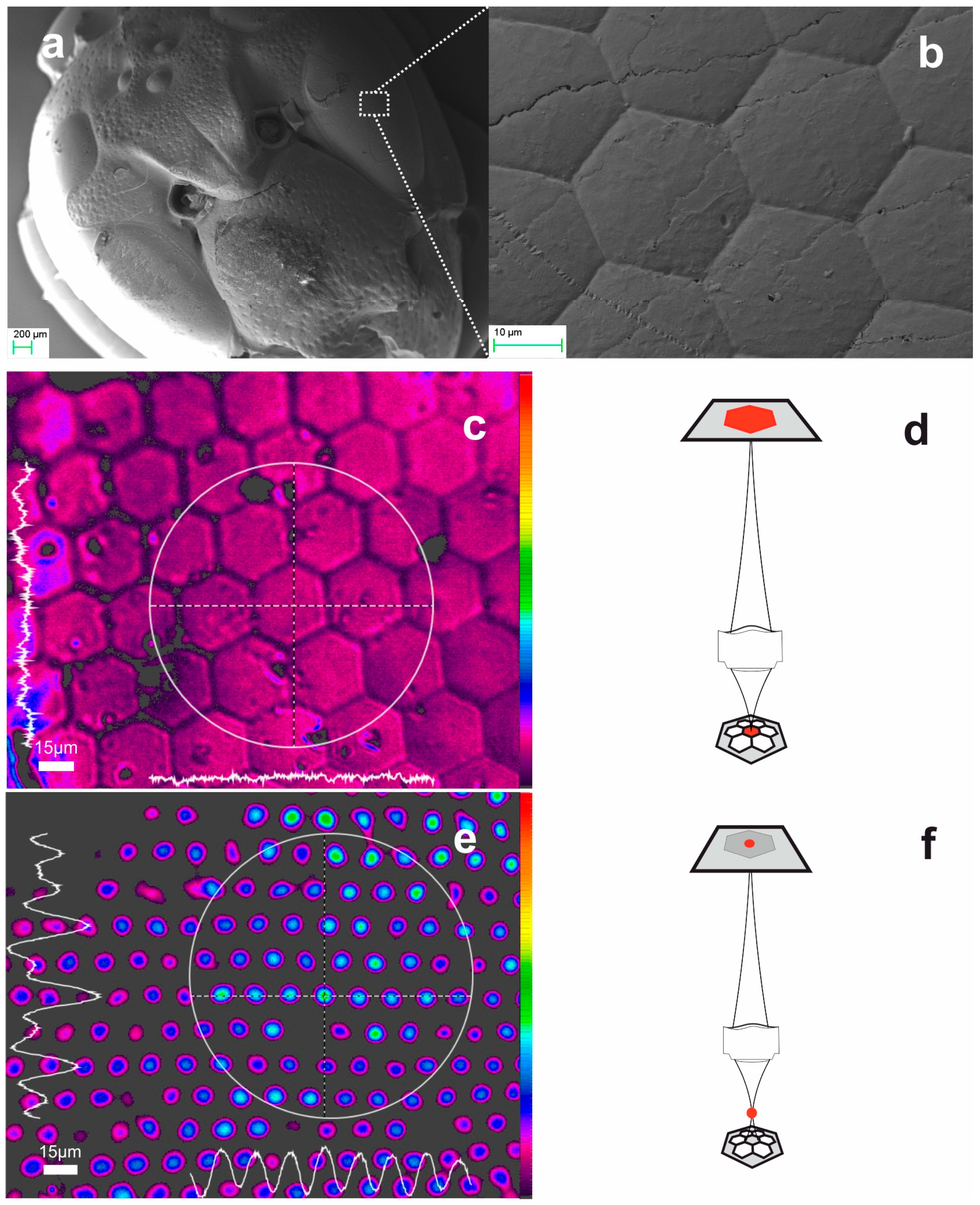
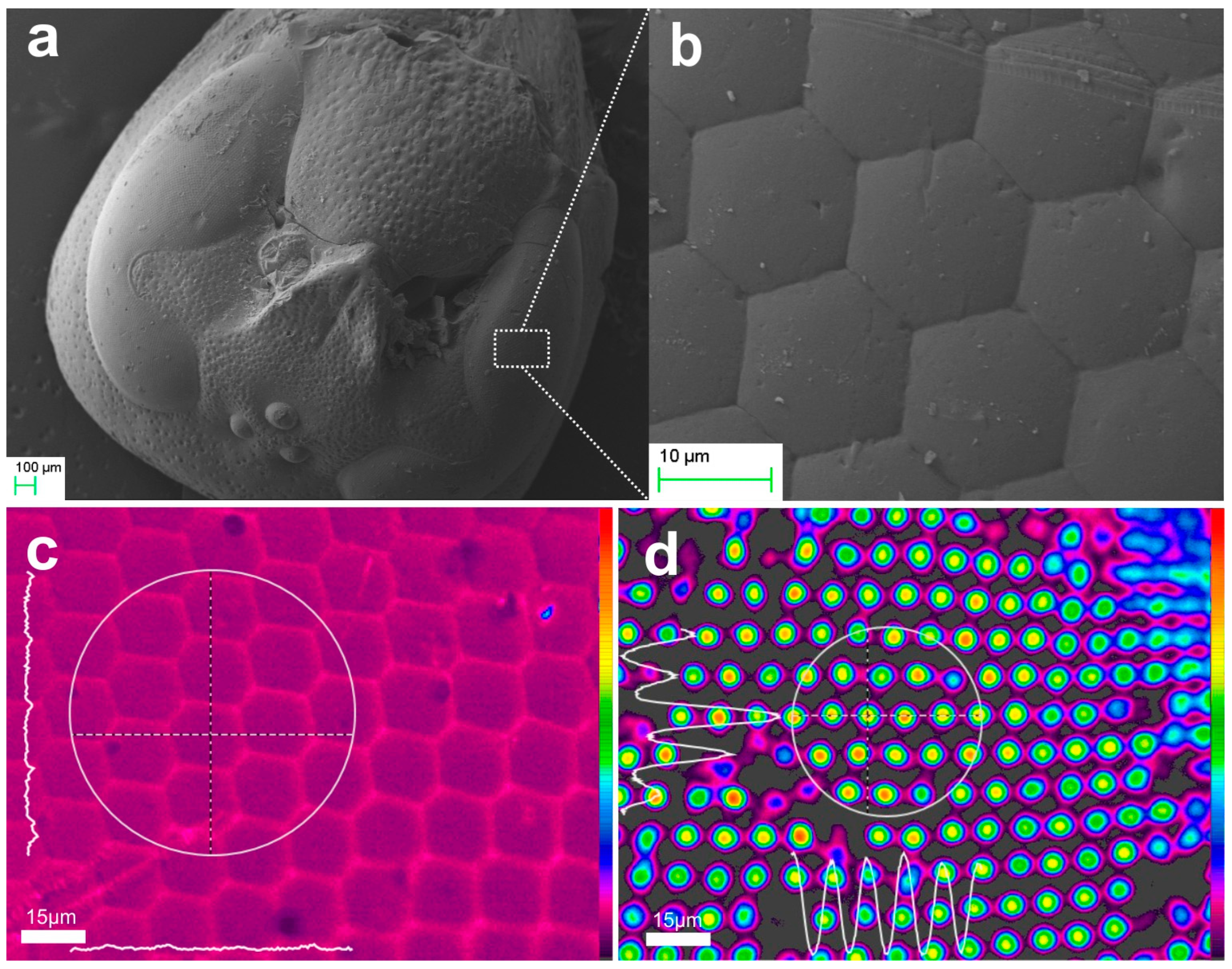
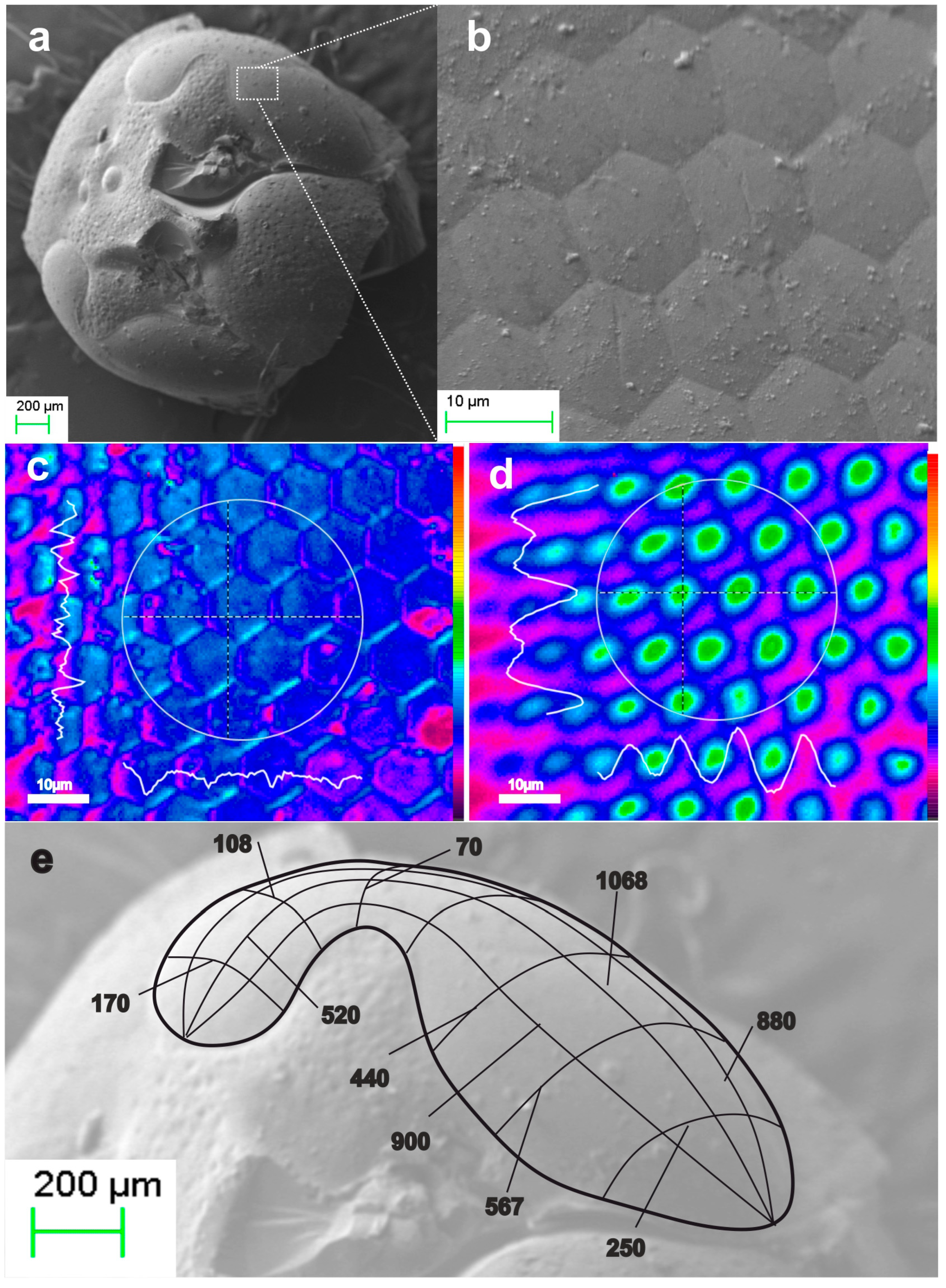
2.2.1. Ommatidia
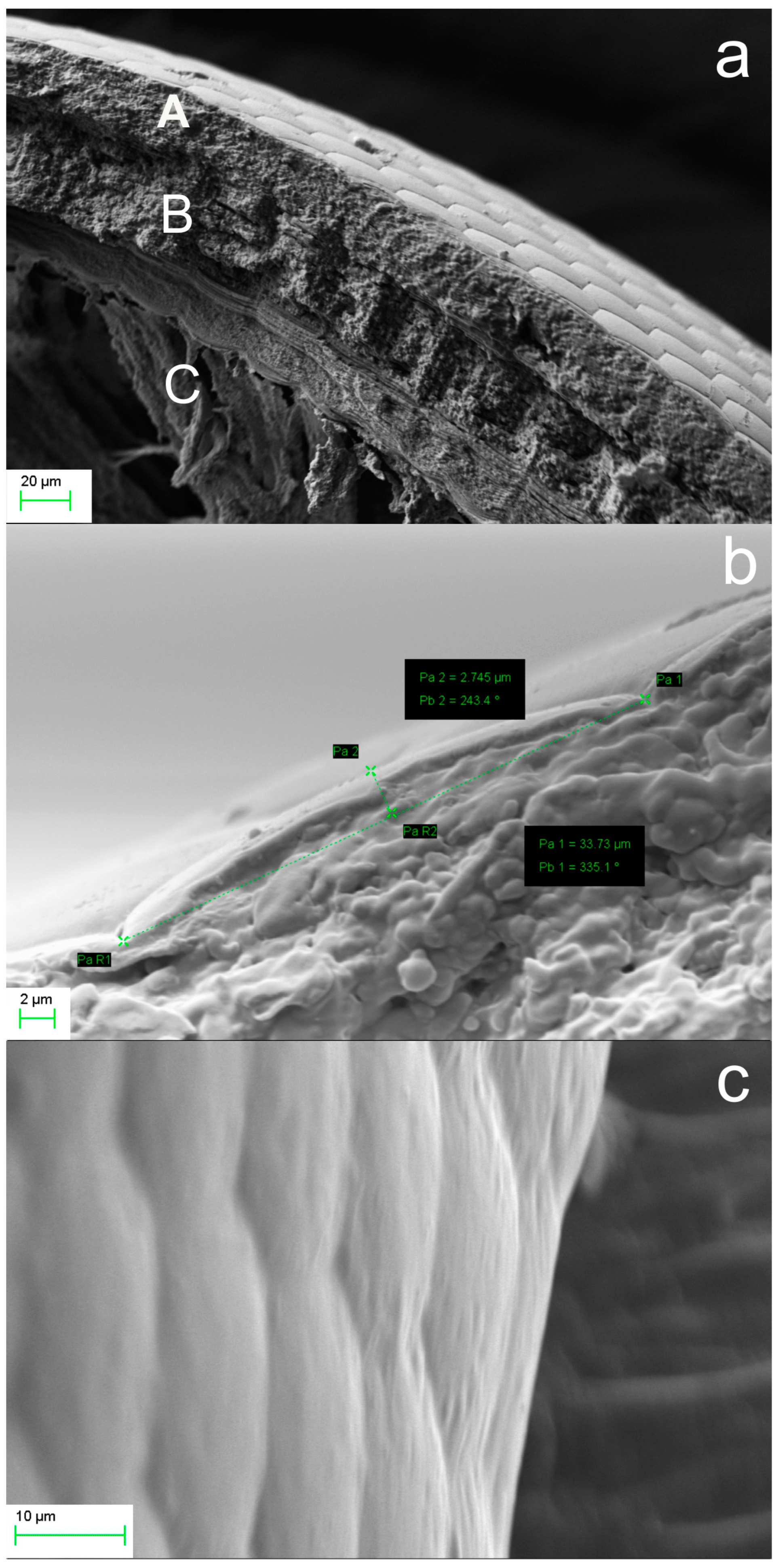
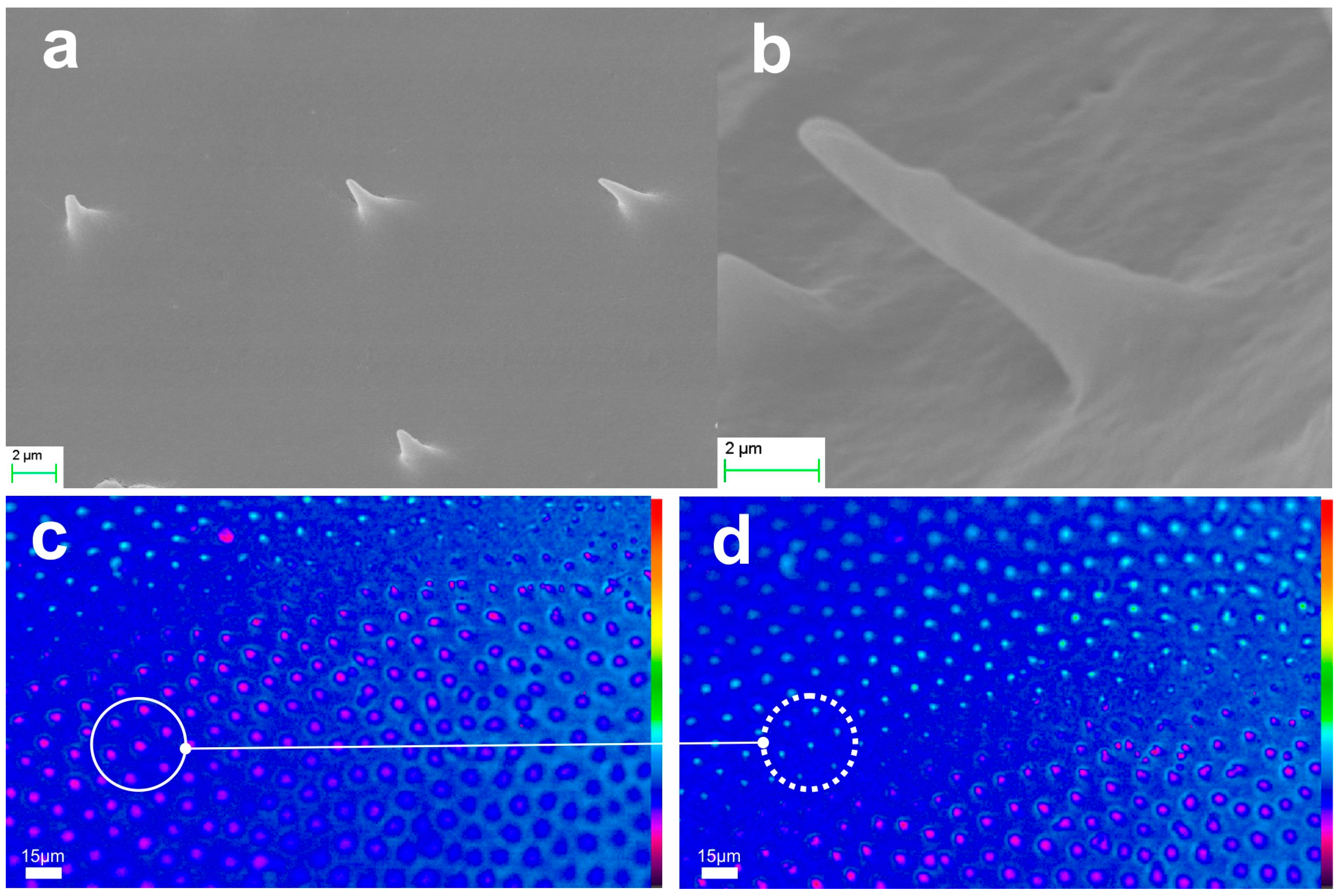
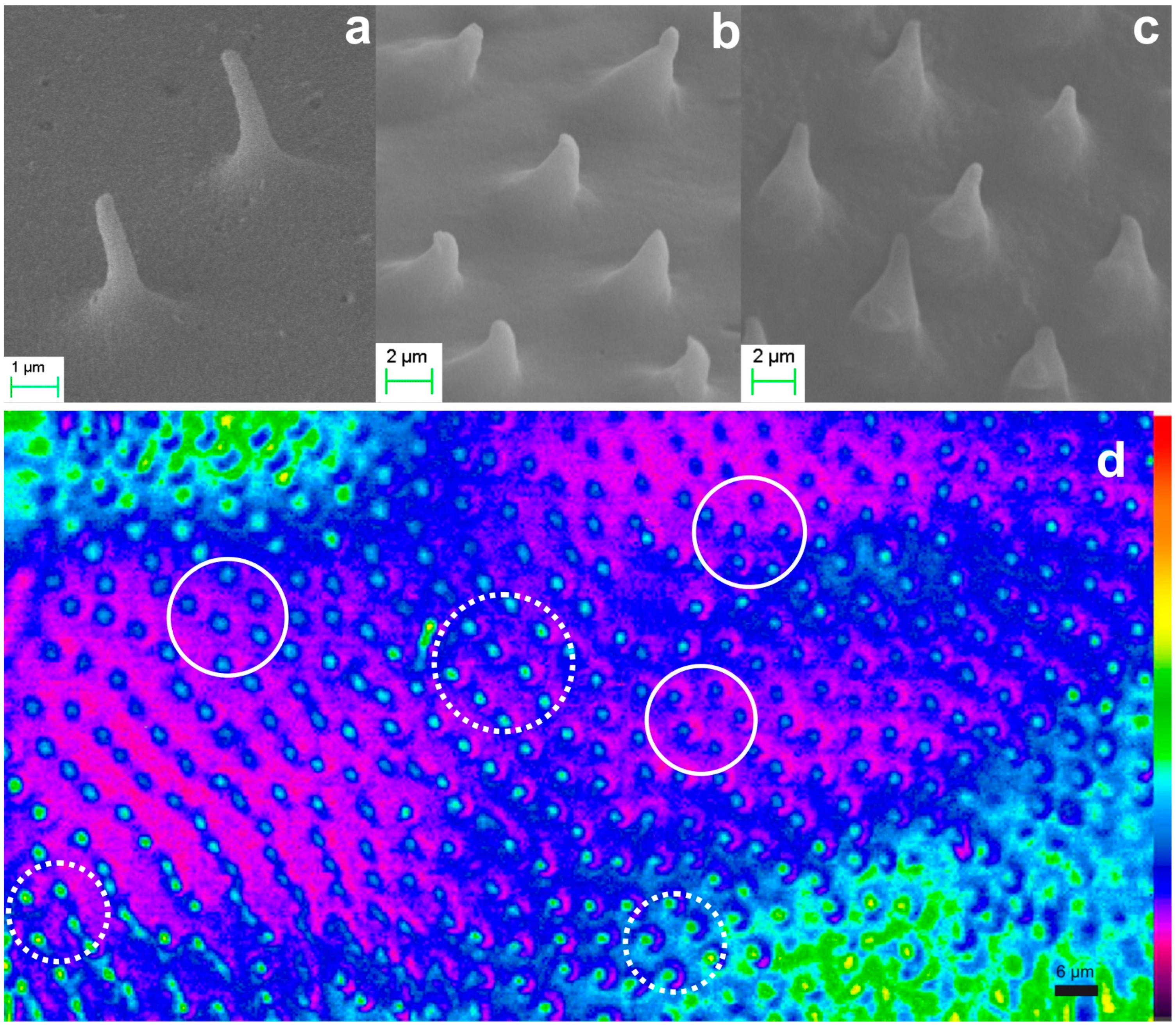
2.2.2. Microtrichia
2.3. Aerogel and Xerogel Solid Replicas
2.4. Systolic Miniaturization of Aerogel and Xerogel Replicas
3. Results and Discussion
3.1. Bioarchitectonics in Biomimetics
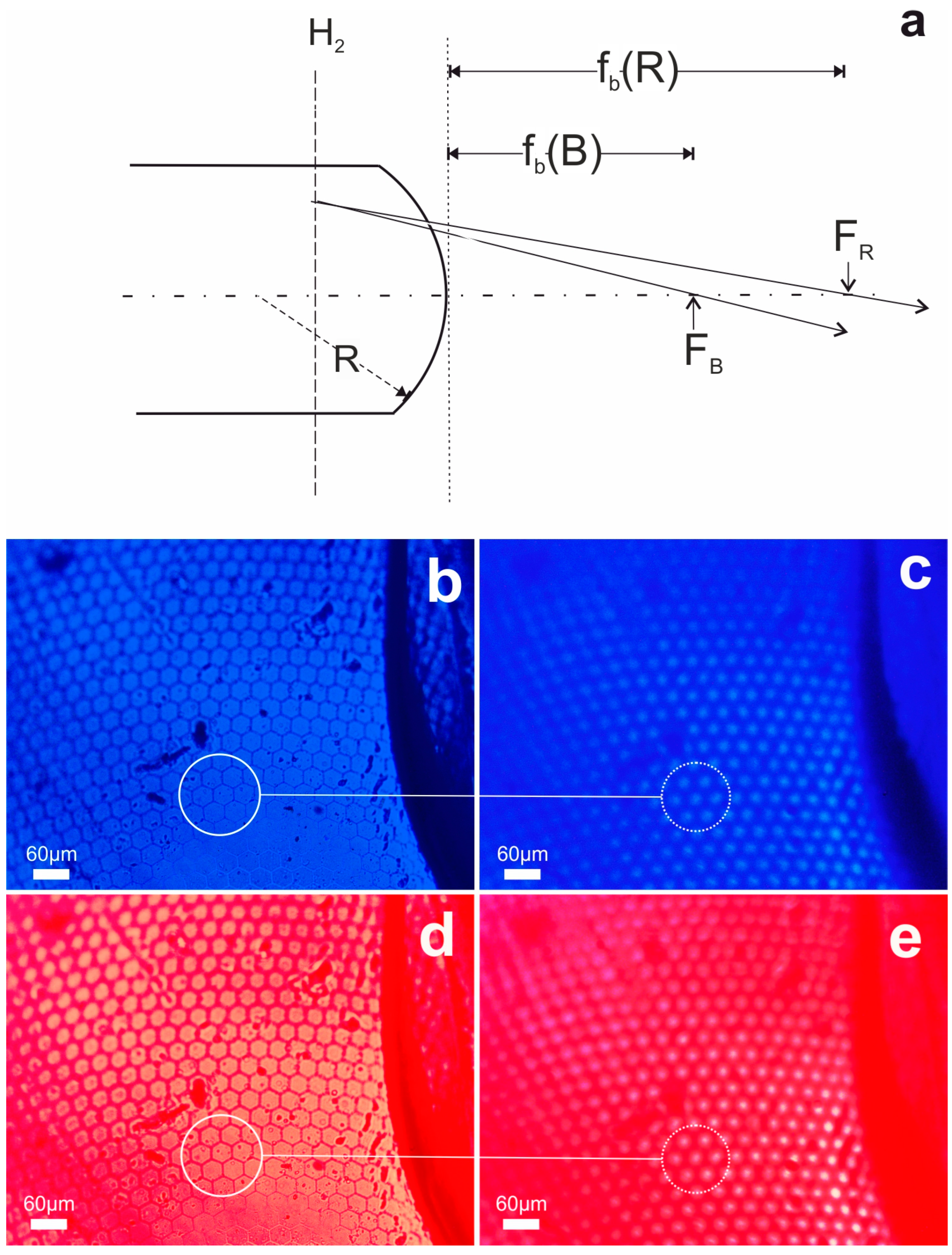
3.2. The Paradigm of Biorchitectonic Compound Eye
3.3. The Paradigm of Bioarchitectonic Microneedles
4. Conclusions
5. Patents
Author Contributions
Funding
Institutional Review Board Statement
Data Availability Statement
Acknowledgments
Conflicts of Interest
References
- Zhao, H.; Lee, Y.; Han, M.; Sharma, B.K.; Chen, X.; Ahn, J.-H.; Rogers, J.A. Nanofabrication approaches for functional three-dimensional architectures. Nano Today 2020, 30, 100825. [Google Scholar] [CrossRef]
- Wang, K.; Ma, Q.; Qu, C.X.; Zhou, H.T.; Cao, M.; Wang, S.D. Review on 3D Fabrication at Nanoscale. Autex Res. J. 2023, 23, 350–369. [Google Scholar] [CrossRef]
- Vainos, N.A. (Ed.) Laser Growth and Processing of Photonic Structures; Woodhead Publishing: Cambridge, UK, 2012. [Google Scholar]
- Zergioti, I.; Koundourakis, G.; Vainos, N.; Fotakis, C. Direct Write Technologies for Rapid Prototyping: Applications to Sensors, Electronics and Passivation Coatings; Pique, A., Chrisey, D.B., Eds.; Academic Press: Washington, DC, USA, 2002; Chapter 8; pp. 493–516. [Google Scholar]
- Chatzipetrou, M.; Massaouti, M.; Tsekenis, G.; Trilling, A.K.; Ande, E.; Scheres, L.; Smulders, M.M.J.; Zuilhof, H.; Zergioti, I. Direct Creation of Biopatterns via a Combination of Laser-Based Techniques and Click Chemistry. Langmuir 2017, 33, 848–853. [Google Scholar] [CrossRef] [PubMed]
- Mills, B.; Grant-Jacob, J.A.; Zervas, M.N. Predictive visualisation of high repetition rate femtosecond machining of silica using deep learning. Opt. Mater. Express 2023, 13, 3641–3652. [Google Scholar] [CrossRef]
- Seok, I.; Kilula, D.; Guo, Z. Micro/Nanoscale 3-Dimensional Fabrication using Multi-Photons Polymerization: Review. ES Mater. Manuf. 2023, 21, 849. [Google Scholar] [CrossRef]
- Merkininkaitė, G.; Aleksandravičius, E.; Varapnickas, S.; Gailevičius, D.; Šakirzanovas, S.; Malinauskas, M. Ultrafast Laser Nanostructuring; Stoian, R., Bonse, J., Eds.; Springer: Cham, Switzerland, 2023; Volume 239, pp. 787–823. [Google Scholar]
- Cummins, C.; Lundy, R.; Walsh, J.J.; Ponsinet, V.; Fleury, G.; Morris, M.A. Enabling future nanomanufacturing through block copolymer self-assembly: A review. Nano Today. 2020, 35, 100936. [Google Scholar] [CrossRef]
- Li, D.; Tian, X.; Yang, W.; Wang, X.; Liu, Y.; Shan, J. Hydrophobicity-driven self-assembly of nanoplastics and silver nanoparticles for the detection of polystyrene microspheres using surface enhanced Raman spectroscopy. Chemosphere 2023, 339, 1–9. [Google Scholar] [CrossRef] [PubMed]
- Braun, P.V. Materials Chemistry in 3D Templates for Functional Photonics. Chem. Mater. 2014, 26, 277–286. [Google Scholar] [CrossRef]
- Naveena, K.; Chinniah, C.; Shanthi, M. Insect micro-morphology and its applications. J. Entomol. Zool. Stud. 2020, 8, 246–254. [Google Scholar]
- Cook, T.A. The Curves of Life; Dover: New York, NY, USA, 1979. [Google Scholar]
- Gwilt, J. An Encyclopedia of Architecture, Historical, Theoretical, & Practical; Longmans, Green & Co.: London, UK, 1888. [Google Scholar]
- Bhushan, B. Biomimetics: Lessons from nature—An overview. Phil. Trans. R. Soc. A 2009, 367, 1445–1486. [Google Scholar] [CrossRef]
- Galloway, J.M.; Bramble, J.P.; Staniland, S.S. Biomimetic Synthesis of Materials for Technology. Chem. Eur. J. 2013, 19, 8710–8725. [Google Scholar] [CrossRef] [PubMed]
- Sun, J.; Chao, L.; Bhushan, B. A review of beetle hindwings: Structure, mechanical properties, mechanism and bioinspiration. J. Mech. Behav. Biomed. Mater. 2019, 94, 63–73. [Google Scholar] [CrossRef] [PubMed]
- Kim, D.H.; Kim, J.J.; Kong, D.J.; Lee, G.J.; Song, Y.M. Bio-inspired tunable optics and photonics: Bridging the gap between nature and technology. Int. J. Optomechatronics 2024, 18, 1–28. [Google Scholar] [CrossRef]
- Serres, J.R.; Viollet, S. Insect-inspired vision for autonomous vehicles. Curr. Opin. Insect Sci. 2018, 30, 46–51. [Google Scholar] [CrossRef]
- Ahmed, T. Bio-inspired artificial synapses: Neuromorphic computing chip engineering with soft biomaterials. Mem. Mater. Devices Circuits Syst. 2023, 6, 10008. [Google Scholar] [CrossRef]
- Jung, Y.C.; Bhushan, B. Biomimetic structures for fluid drag reduction in laminar and turbulent flows. J. Phys. Condens. Matter 2010, 22, 035104. [Google Scholar] [CrossRef] [PubMed]
- Zhang, C.; Mcadams II, D.A.; Grunlan, J.C. Nano/Micro-Manufacturing of Bioinspired Materials: A Review of Methods to Mimic Natural Structures. Adv. Mater. 2016, 28, 6292–6321. [Google Scholar] [CrossRef] [PubMed]
- Schroeder, T.B.H.; Houghtaling, J.; Wilts, B.D.; Mayer, M. It’s Not a Bug, It’s a Feature: Functional Materials in Insects. Adv. Mater. 2018, 30, 1705322. [Google Scholar] [CrossRef]
- Barrera-Patiño, C.P.; Vollet-Filho, J.D.; Teixeira-Rosa, R.G.; Quiroz, H.P.; Dussan, A.; Inada, N.M.; Bagnato, V.S.; Rey-González, R.R. Photonic effects in natural nanostructures on Morpho cypris and Greta oto butterfly wings. Sci. Rep. 2020, 10, 5786. [Google Scholar] [CrossRef]
- Parisotto, A.; Vogler-Neuling, V.V.; Steiner, U.; Saba, M.; Wilts, B.D. Structural light absorption in elytral micropillars of Euprotaetia inexpectata beetles. Mater. Today Adv. 2023, 19, 100399. [Google Scholar] [CrossRef]
- Yu, K.; Fan, T.; Lou, S.; Zhang, D. Biomimetic optical materials: Integration of nature’s design for manipulation of light. Prog. Mater. Sci. 2013, 58, 825–873. [Google Scholar] [CrossRef]
- Adhikary, M.; Uppu, R.; Harteveld, C.A.M.; Grishina, D.A.; Vos, W.L. Experimental probe of a complete 3D photonic band gap. Opt. Express 2020, 28, 2683. [Google Scholar] [CrossRef] [PubMed]
- Parker, G.J. Biomimetically-inspired photonic nanomaterials. J. Mater Sci Mater. Electron. 2010, 21, 965–979. [Google Scholar] [CrossRef]
- Ragaei, M.; Sabry, A.K.H.; Abdel-Rahman, A. Insect’s photonic crystals and their applications. Bioscience Research. 2016, 13, 15–20. [Google Scholar]
- Seago, A.E.; Brady, P.; Vigneron, J.P.; Schultz, T.D. Gold bugs and beyond: A review of iridescence and structural colour mechanisms in beetles (Coleoptera). J. R. Soc. Interface 2009, 6, S165–S184. [Google Scholar] [CrossRef] [PubMed]
- Brunner, R.; Sandfuchs, O.; Pacholski, C.; Morhard, C.; Spatz, J. Lessons from nature: Biomimetic subwavelength structures for high-performance optics. Laser Photonics Rev. 2012, 6, 641–659. [Google Scholar] [CrossRef]
- Hooke, R. Micrographia, or Some Physiological Descriptions of Minute Bodies Made by Magnifying Glasses, with Observations and Inquiries Thereupon; Royal Society: London, UK, 1665. [Google Scholar]
- Miller, W.H.; Bernard, G.D.; Allen, J.L. The Optics of Insect Compound Eyes: Microcomponents with dimensions near a wavelength of light cause observable optical effects. Science 1968, 162, 760–766. [Google Scholar] [CrossRef]
- Yuan, W.; Li, L.H.; Lee, W.B.; Chan, C.Y. Fabrication of Microlens Array and Its Application: A Review. Chin. J. Mech. Eng. 2018, 31, 1–9. [Google Scholar] [CrossRef]
- Chang, S.; Kong, D.J.; Song, Y.M. Advanced visual components inspired by animal eyes. J. Nanophotonics 2024, 13, 859–879. [Google Scholar] [CrossRef]
- Zhang, S.; Wu, Q.; Liu, C.; Wang, T.; Zhang, H.; Wang, J.; Ding, Y.; Chi, J.; Xu, W.; Xiang, Y.; et al. Bio-inspired spherical compound eye camera for simultaneous wide-band and large field of view imaging. Opt. Express 2022, 30, 20952. [Google Scholar] [CrossRef]
- Martín-Palma, R.J.; Kolle, M. Biomimetic photonic structures for optical sensing. Opt. Laser Technol. 2019, 109, 270–277. [Google Scholar] [CrossRef]
- Yang, Q.; Li, M.; Bian, H.; Yong, J.; Zhang, F.; Hou, X.; Chen, F. Bioinspired Artificial Compound Eyes: Characteristic, Fabrication, and Application. Adv. Mater. Technol. 2021, 6, 2100091. [Google Scholar] [CrossRef]
- Kuo, W.K.; Kuo, G.F.; Lin, S.Y.; Yu, H.H. Fabrication and characterization of artificial miniaturized insect compound eyes for imaging. Bioinspir. Biomim. 2015, 10, 056010. [Google Scholar] [CrossRef] [PubMed]
- Deng, H.; Luan, S.; Cao, H.; Wan, H.; Song, Y.; Gui, C. 3D lithography enable ultrathin flat compound eye for moving object imaging. Opt. Lasers Eng. 2023, 169, 107698. [Google Scholar] [CrossRef]
- Jin, G.X.; Hu, X.Y.; Ma, Z.C.; Li, C.H.; Zhang, Y.L.; Sun, H.B. Femtosecond laser fabrication of 3D templates for mass production of artificial compound eyes. Nanotechnol. Precis. Eng. 2019, 2, 110–117. [Google Scholar] [CrossRef]
- Zhang, F.; Xu, H.; Yang, Q.; Lu, Y.; Du, G.; Chen, F. Femtosecond Laser Microfabrication of Artificial Compound Eyes. Photonics 2024, 11, 264. [Google Scholar] [CrossRef]
- Zhu, Y.; Zhang, C.; Hong, M. Free-Form Micro-Lens Array Fabrication via Laser Micro-Lens Array Lithography. JLMN 2024, 19, 67–71. [Google Scholar]
- Zolfaghari, A.; Zhang, L.; Zhou, W.; Yi, A.Y. Replication of plastic microlens arrays using electroforming and precision compression molding. Microelectron. Eng. 2021, 239–240, 111529. [Google Scholar] [CrossRef]
- Paulraj, T.; Feoktistova, N.; Velk, N.; Uhlig, K.; Duschl, C.; Volodkin, D. Microporous Polymeric 3D Scaffolds Templatedby the Layer-by-Layer Self-Assembly. Macromol. Rapid Commun. 2014, 35, 1408–1413. [Google Scholar] [CrossRef]
- Yang, Y.; Song, X.; Li, X.; Chen, Z.; Zhou, C.; Zhou, Q.; Chen, Y. Recent Progress in Biomimetic Additive Manufacturing Technology: From Materials to Functional Structures. Adv. Mater. 2018, 30, 1–34. [Google Scholar] [CrossRef]
- Zhai, Y.; Han, Q.; Niu, J.; Liu, J.; Yang, B. Microfabrication of bioinspired curved artificial compound eyes: A review. Microsyst. Technol 2021, 27, 3241–3262. [Google Scholar] [CrossRef]
- Auzelyte, V.; Flauraud, V.; Cadarso, V.J.; Kiefer, T.; Brugger, J. Biomimetic soft lithography on curved nanostructured surfaces. Microelectron. Eng. 2012, 97, 269–271. [Google Scholar] [CrossRef]
- Gao, W.; Xu, Z.; Han, X.; Pan, C. Recent advances in curved image sensor arrays for bioinspired vision system. Nano Today 2022, 42, 101366. [Google Scholar] [CrossRef]
- Navarro, R.; Franceschini, N. On image quality of microlens arrays in diurnal superposition eyes. Pure Appl. Opt. 1998, 7, L69. [Google Scholar] [CrossRef]
- Davis, J.D.; Barrett, S.F.; Wright. C.H.G.; Wilcox, M. A bio-inspired apposition compound eye machine vision sensor system. Bioinsp. Biomim. 2009, 4, 1–11. [Google Scholar] [CrossRef] [PubMed]
- Brückner, A.; Duparré, J.; Bräuer, A.; Tünnermann, A. Position detection with hyperacuity using artificial compound eyes. In Proceedings of the SPIE 6501 Conference on Sensors, Cameras, and Systems for Scientific/Industrial Applications VII, San Jose, CA, USA, 28 January–1 February2007. [Google Scholar]
- Rad, Z.F.; Prewett, P.D.; Davies, G.J. An Overview of Microneedle Applications, Materials, and Fabrication Methods. Beilstein J. Nanotechnol. 2021, 12, 1034–1046. [Google Scholar]
- Makvandi, P.; Maleki, A.; Shabani, M.; Hutton, A.R.J.; Kirkby, M.; Jamaledin, R.; Fang, T.; He, J.; Lee, J.; Mazzolai, B.; et al. Bioinspired microneedle patches: Biomimetic designs, fabrication, and biomedical applications. Matter 2022, 5, 390–429. [Google Scholar] [CrossRef]
- Wei, X.; Wang, Y.; Liu, Y.; Ji, K.; Li, K.; Wang, J.; Gu, Z. Biomimetic design strategies for biomedical applications. Matter 2024, 7, 826–854. [Google Scholar] [CrossRef]
- Machekposhti, S.A.; Khanna, S.; Shukla, S.; Narayan, R. Microneedle fabrication methods and applications. MRS Commun. 2023, 13, 212–224. [Google Scholar] [CrossRef]
- Rad, Z.F.; Prewett, P.D.; Davies, G.J. Rapid prototyping and customizable microneedle design: Ultra-sharp microneedle fabrication using two-photon polymerization and low-cost micromolding techniques. Manuf. Lett. 2021, 30, 39–43. [Google Scholar]
- Sankabathula, G.T.R.; Valluri, S.; Norden, N.; Binderup, S.; Sumant, A.; Divan, R.; Mohsen, O.; Piot, P.; Korampally, V. Shape tuning of large area silicon nanotip arrays through reactive ion etching. J. Vac. Sci. Technol. B 2023, 41, 062605. [Google Scholar] [CrossRef]
- Rahman, A.; Ashraf, A.; Xin, H.; Tong, X.; Sutter, P.; Eisaman, M.D.; Black, C.T. Sub-50-nm self-assembled nanotextures for enhanced broadband antireflection in silicon solar cells. Nat. Commun. 2015, 6, 5963. [Google Scholar] [CrossRef] [PubMed]
- Hulst, N.F.V.; Moers, M.H.P.; Bolger, B. Near-field optical microscopy in transmission and reflection modes in combination with force microscopy. J. Microsc. 1993, 171, 95–105. [Google Scholar] [CrossRef]
- Matějec, V.; Kašík, I.; Bartoň, I. Fiber-Optic Nanosensors for Chemical Detection. Chemosensors 2023, 11, 521. [Google Scholar] [CrossRef]
- Dam, T.H.; Pantano, P. Nanotip array photoimprint lithography. Rev. Sci. Instrum. 1999, 70, 3982–3986. [Google Scholar] [CrossRef]
- Rockstuhl, C.; Simovski, C.R.; Tretyakov, S.A.; Lederer, F. Metamaterial nanotips. Appl. Phys. Lett. 2009, 94, 113110. [Google Scholar] [CrossRef]
- Fain, R.; Barbosa, F.; Cardenas, J.; Lipson, M. Photonic Needles for Light Delivery in Deep Tissue-like Media. Sci. Rep. 2017, 7, 5627. [Google Scholar] [CrossRef]
- Androulidaki, M.; Boussey, J.; Tsagaraki, K.; Stavrinidis, A.; Kostopoulos, A.; Papachristopoulou, K.; Konstantinidis, G.; Zekentes, K.; Vainos, N.A. Photonic and plasmonic responses of silicon carbide nanopillars and their aerogel clones. In Proceedings of the 10th International Conference on Micro-Nanoelectronics, Nanotechnology and MEMS, Athens, Greece, 2–5 November 2023. [Google Scholar]
- Huang, Y.F.; Jen, Y.J.; Chen, L.C.; Chen, K.H.; Chattopadhyay, S. Design for Approaching Cicada-Wing Reflectance in Low- and High-Index Biomimetic Nanostructures. ACS Nano 2015, 9, 301–311. [Google Scholar] [CrossRef]
- Williams, M.H.; Vesk, M.; Mullins, M.G. Tissue preparation for scanning electron microscopy of fruit surfaces: Comparison of fresh and cryopreserved specimens and replicas of banana peel. Micron Microsc. Acta. 1987, 18, 27–31. [Google Scholar] [CrossRef]
- Williams, M.H.; Green, P.B. Sequential Scanning Electron Microscopy of a Growing Plant Meristem. Protoplasma 1988, 147, 77–79. [Google Scholar] [CrossRef]
- Green, P.B.; Linstead, P. A procedure for SEM of complex shoot structures applied to the inflorescence of snapdragon (Antirrhinum). Protoplasma 1990, 158, 33–38. [Google Scholar] [CrossRef]
- Zhu, S.; Zhang, D.; Chen, Z.; Gu, J.; Li, W.; Jiang, H.; Zhou, G. A simple and effective approach towards biomimetic replication of photonic structures from butterfly wings. Nanotechnology 2009, 20, 315303. [Google Scholar] [CrossRef] [PubMed]
- Vasileiou, M.; Mpatzaka, T.; Alexandropoulos, D.; Vainos, N.A. Biomimetic microstructures for photonic and fluidic synergies. Optofluid. Microfluid. Nanofluid. 2017, 4, 1–6. [Google Scholar] [CrossRef]
- Papachristopoulou, K.; Vainos, N. Systolic Nanofabrication of Super-Resolved Photonics and Biomimetics. Nanomaterials 2020, 10, 2418. [Google Scholar] [CrossRef]
- Wang, J.; Zhou, W.; Liu, Y.; He, G.; Yang, Y. Biomimetic Compound Eyes with Gradient Ommatidium Arrays. ACS Appl. Mater. Interfaces 2023, 15, 44503–44512. [Google Scholar] [CrossRef] [PubMed]
- Li, X.; Li, H.; Zhao, K.; Wang, H.; Zhang, Z.; Huang, L.; Niu, H.; Yang, Z.; Wang, C. Biomimetic flexible SERS substrates replicated from cicada wings for portable in situ detection. Opt. Mater. 2024, 149, 11480. [Google Scholar] [CrossRef]
- Woignier, T.; Phallippou, J.; Prassas, M. Glasses from aerogels Part 1: The synthesis of monolithic silica aerogels. J. Mater. Sci. 1990, 25, 3111–3117. [Google Scholar]
- Woignier, T.; Phallippou, J.; Prassas, M. Glasses from aerogels Part 2: The aerogel-glass transformation. J. Mater. Sci. 1990, 25, 3118–3126. [Google Scholar] [CrossRef]
- Kreuzberger, T.; Harnisch, A.; Helgert, M.; Erdmann, L.; Brunner, R. Sol–Gel Process to Cast Quartz Glass Microlens Arrays. Microelectron. Eng. 2009, 86, 1173–1175. [Google Scholar] [CrossRef]
- Vainos, N.A.; Karoutsos, V.; Mills, B.; Eason, R.W.; Prassas, M. Contractive scaling of 3-dimensional laser written micro-structures via vitrification of silica aerogel monoliths. Opt. Mater. Express 2016, 6, 3814–3825. [Google Scholar] [CrossRef]
- Papachristopoulou, K.; Vainos, N. Systolic Nanofabrication of Photonic Bioarchitectures. In Proceedings of the OSA Advanced Photonics Congress 2021, Washington, DC, USA, 26–29 July 2021. [Google Scholar]
- Satoshi, T. New Field of Insect Science: Research on the Use of Insect Properties. Entomol. Sci. 2013, 16, 125–135. [Google Scholar]
- Kelber, A.; Jonsson, F.; Wallén, R.; Warrant, E.; Kornfeldt, T.; Baird, E. Hornets Can Fly at Night without Obvious Adaptations of Eyes and Ocelli. PLoS ONE 2011, 6, e21892. [Google Scholar] [CrossRef]
- Chen, Q.X.; Hua, B.Z. Ultrastructure and Morphology of Compound Eyes of the Scorpionfly Panorpa Dubia (Insecta: Mecoptera: Panorpidae). PLoS ONE 2016, 11, e21892. [Google Scholar] [CrossRef]
- Sun, J.; Liu, C.; Bhushan, B.; Wu, W.; Tong, J. Effect of microtrichia on the interlocking mechanism in the Asian ladybeetle, Harmonia axyridis (Coleoptera: Coccinellidae). Beilstein J. Nanotechnol. 2018, 9, 812–823. [Google Scholar] [CrossRef] [PubMed]
- Goczał, J.; Beutel, R.G. Beetle elytra: Evolution, modifications and biological functions. Biol. Lett. 2023, 19, 20220559. [Google Scholar] [CrossRef]
- Kistler, S.S. Coherent expanded aerogels. J. Phys. Chem. 1932, 36, 52–64. [Google Scholar] [CrossRef]
- Michaloudis, I.; Rao, A.V.; Kanamori, K. Sky-Mimesis, a Path from Nanotechnology to Visual Arts: A Review of Art Applications of Aerogels. MNE 2024, 23, 100248. [Google Scholar] [CrossRef]
- Rao, A.P.; Rao, A.V.; Pajonk, G.M. Hydrophobic and physical properties of the ambient pressure dried silica aerogels with sodium silicate precursor using various surface modification agents. Appl. Surf. Sci. 2007, 253, 6032–6040. [Google Scholar] [CrossRef]
- Scherer, G.W. Sintering of Low-Density Glasses: I. Theory. J. Am. Ceram. Soc. 1977, 60, 5–6. [Google Scholar] [CrossRef]
- Siegman, A.E. Defining the Effective Radius of Curvature for a Nonideal Optical Beam. IEEE J. Quantum Electron. 1991, 27, 1146–1148. [Google Scholar] [CrossRef]
- Gupta, R.K.; Asanuma, H.; Giner-Casares, J.J.; Hashimoto, A.; Ogawa, T.; Nakanishi, T. A compound eye-like morphology formed through hexagonal array of hemispherical microparticles where an alkyl-fullerene derivative self-assembled at atmosphere-sealed air/water interface. Nanotechnology 2024, 35, 1–11. [Google Scholar] [CrossRef] [PubMed]
- Tripathi, A.; Chokshi, T.V.; Chronis, N. A high numerical aperture, polymer-based, planar microlens array. Opt. Express 2009, 17, 19909. [Google Scholar] [CrossRef]
- Zhang, Y.; Xu, H.; Guo, Q.; Wu, D.; Yu, W. Biomimetic multispectral curved compound eye camera for real-time multispectral imaging in an ultra-large field of view. Opt. Express 2021, 29, 33346–33356. [Google Scholar] [CrossRef] [PubMed]


Disclaimer/Publisher’s Note: The statements, opinions and data contained in all publications are solely those of the individual author(s) and contributor(s) and not of MDPI and/or the editor(s). MDPI and/or the editor(s) disclaim responsibility for any injury to people or property resulting from any ideas, methods, instructions or products referred to in the content. |
© 2024 by the authors. Licensee MDPI, Basel, Switzerland. This article is an open access article distributed under the terms and conditions of the Creative Commons Attribution (CC BY) license (https://creativecommons.org/licenses/by/4.0/).
Share and Cite
Papachristopoulou, K.; Vainos, N.A. Bioarchitectonic Nanophotonics by Replication and Systolic Miniaturization of Natural Forms. Biomimetics 2024, 9, 487. https://doi.org/10.3390/biomimetics9080487
Papachristopoulou K, Vainos NA. Bioarchitectonic Nanophotonics by Replication and Systolic Miniaturization of Natural Forms. Biomimetics. 2024; 9(8):487. https://doi.org/10.3390/biomimetics9080487
Chicago/Turabian StylePapachristopoulou, Konstantina, and Nikolaos A. Vainos. 2024. "Bioarchitectonic Nanophotonics by Replication and Systolic Miniaturization of Natural Forms" Biomimetics 9, no. 8: 487. https://doi.org/10.3390/biomimetics9080487
APA StylePapachristopoulou, K., & Vainos, N. A. (2024). Bioarchitectonic Nanophotonics by Replication and Systolic Miniaturization of Natural Forms. Biomimetics, 9(8), 487. https://doi.org/10.3390/biomimetics9080487