1. Introduction
Antarctic krill (
Euphausia superba) plays a pivotal role as a “keystone species” within the Antarctic ecosystem, and it stands out as one of the largest single-species harvestable resources found in the ocean [
1,
2]. With its rich protein content and valuable unsaturated fats, it holds considerable nutritional significance and offers tremendous potential for commercial exploitation [
3]. Its commercial development has garnered much attention from various countries, given its substantial economic value and extensive prospects for growth [
4].
Commercial harvesting of Antarctic krill began in the 1970s and was initially conducted primarily by the former Soviet Union, Japan, and South Korea. In recent years, Norway and China have seen a gradual increase in their krill catch [
5]. Since 2010, Norway has been the leading nation in Antarctic krill fishing. In 2014, Norwegian catches of Antarctic krill accounted for approximately 58% of the total landed krill, followed by South Korea and China [
5].
The Antarctic krill is a smaller mesopelagic species with a lower swimming speed [
6]; therefore, the midwater trawl is the primary fishing gear used for catching this species. Many scholars have conducted research on the design and optimization of the midwater trawl for Antarctic krill. For example, Wan et al. [
2] designed a large Antarctic krill trawl with good hydrodynamic performance, enabling efficient krill harvesting. Feng et al. [
7] investigated the impacts of different structural parameters on the Antarctic krill trawl and provided optimization recommendations. Nsangue et al. [
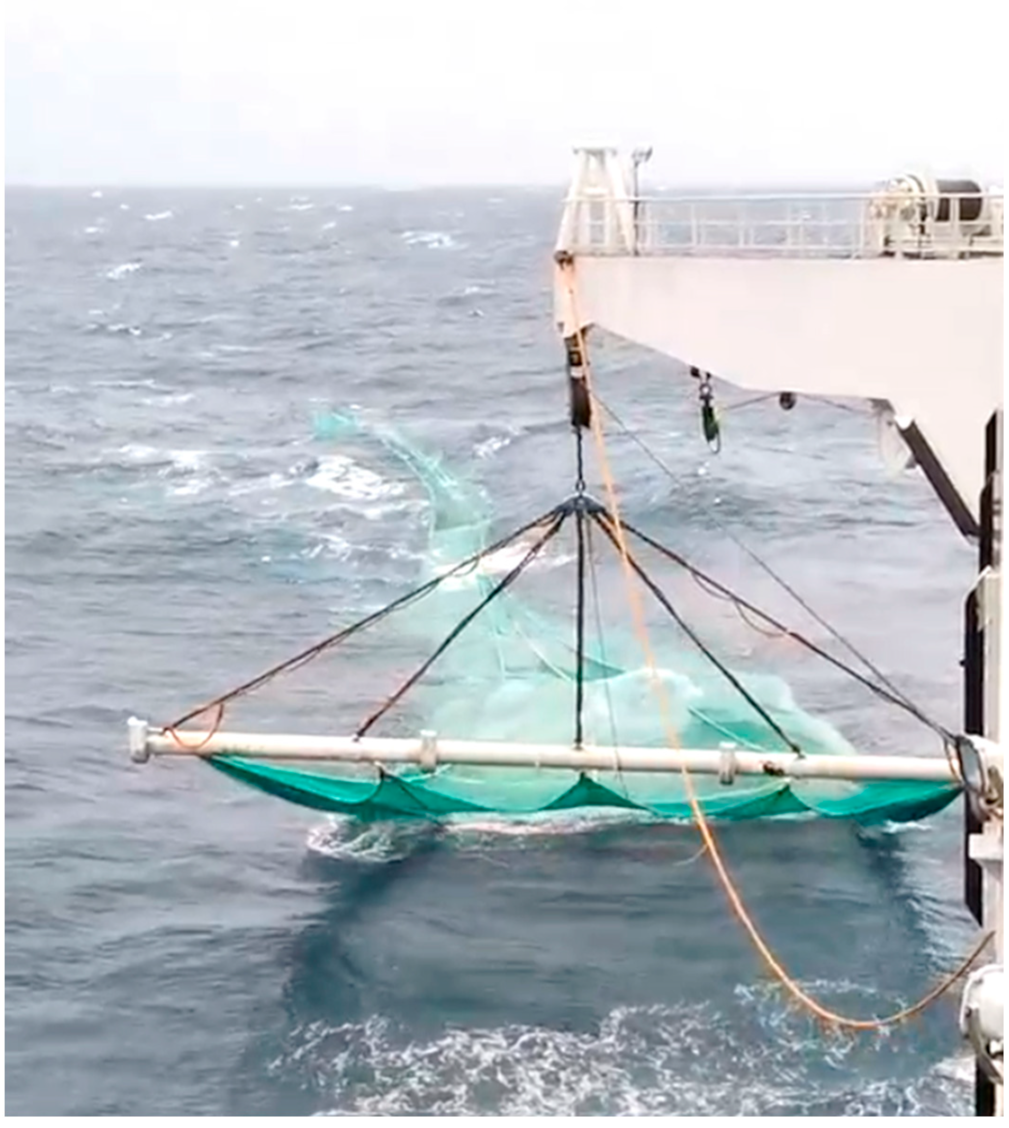
6] studied the effects of flow velocity, horizontal expansion ratio, sinker weight, buoyancy, and other factors on the performance of the Antarctic krill trawl. Currently, Antarctic krill harvesting is primarily carried out using two main types: the traditional otter trawl and the innovative continuous pump suction-type beam trawl (
Figure 1) [
8,
9]. Norwegian fishing vessels utilizing the continuous pump suction-type beam trawl achieved an average annual catch per vessel that was more than three times higher than traditional single-ship otter trawl fishing vessels [
10]. Under the total catch quota management system implemented in the Antarctic krill fishery [
11], the continuous pump suction-type beam trawl shows promising and widespread applications.
The continuous pump suction-type beam trawl utilizes a pump suction system installed at the end of the trawl net’s cod-end. This system continuously transports the krill from the cod-end to storage holds on the ship through a conveying pipe, allowing for continuous underwater harvesting and production that can last for several days to weeks [
12,
13]. However, achieving high fishing efficiency with the continuous pump suction-type beam trawl in the Antarctic krill fishery depends on crucial factors, such as controlling the expansion of the trawl mouth during continuous harvesting and effectively adjusting the gear to the depth where the krill populations are located. This is because Antarctic krill exhibit irregular clustering and vertical movements, including diurnal vertical migration [
14,
15], which necessitates the careful control and adaptation of the gear during the harvesting process.
The headline of the beam trawl is fixed on the trawl beam, serving to uphold the horizontal expansion of the trawl. This ensures that the trawl’s horizontal expansion remains stable, unaffected by the influence of waves and currents. Nevertheless, the hydrodynamic performance of the beam has a significant impact on the sinking performance, vertical expansion performance, and energy consumption of the fishing vessel. It is inconvenient to adjust the operating water layer of the fishing gear for the traditional beam trawl. However, by changing the shape of the beam, its hydrodynamics can be harnessed to provide lift or sink forces to the trawl, achieving the purpose of adjusting the operating water layer. Therefore, it is necessary to conduct research on the hydrodynamic performance of the trawl beam.
The methods for the hydrodynamic performance of fishing gear and its components include offshore measurements, model experiments, and numerical simulations. Due to factors such as high costs, the time-consuming nature, and uncontrollable testing conditions, offshore measurements are significantly affected. Consequently, model experiments and numerical simulations are widely applied, due to their convenience and controllable testing conditions [
16,
17,
18,
19].
To investigate the hydrodynamic performances of different structural beams, the beam used on the “Shen Lan” krill trawler (
Figure 2) served as the prototype. Three types of beams were designed: cylindrical, elliptical, and airfoil-shaped. Numerical simulations were employed to analyze the hydrodynamic performances of these three beams. Furthermore, the numerical simulation results were validated through model tests conducted in a circulating water tank. The results of this study are expected to serve as a theoretical foundation for the research and optimization design of the trawl beam’s hydrodynamic performance.
3. Results
3.1. Validation
In order to verify the accuracy of the numerical simulation method selected in this study, a comparative study was conducted between the flume test and numerical simulations on the airfoil and cylindrical beams. The relationship between hydrodynamic coefficients (
CL,
CD) of the airfoil beam (model 2) and
Re for each AOA are depicted in
Figure 11. As shown in the figures, the
CL and
CD for the beam exhibited a tendency to stabilize when the flow velocity exceeded 0.36 m/s (
Re > 1.35 × 10
5), and it was in the critical
Re region [
30] or the so-called self-modeling region [
27]. Therefore, the
CL and
CD of the beams are discussed in the following sections with the flow velocity of 0.4 m/s (
Re = 1.50 × 10
4).
The
CL and
CD for the airfoil beam and cylindrical beam are presented in
Figure 12 and
Figure 13, reflecting data from the flume test and numerical simulation. The numerical simulation results exhibited a consistent trend when compared with the results from the flume test.
For the cylindrical beam, the CD remained between 0.954 and 1.084 (based on the flume test) and between 0.825 and 1.043 (based on numerical simulation) for AOAs ranging from −60° to 60°. Overall, there was a tendency for the CD to increase with the increasing absolute value of the AOA. Results from both the flume test and the numerical simulation showed that for the AOA less than 0°, the CD of the beam increased from 0.854 to 1.084 and from 0.925 to 1.036 as the absolute value of the AOA increased, respectively. For the AOA greater than 0°, the CD increased with the increasing AOA and reached its maximum value at an AOA of 45°, being 1.063 and 0.043, respectively. For the AOA greater than 45°, the CD of the beam started to decrease. The numerical simulation results can accurately simulate the values and trends of the drag coefficient of the cylindrical beam, with an average error of 3.24%. The CL remained between −0.056 and 0.032 (based on flume test) and between −0.087 and 0.075 (based on numerical simulation) for AOAs ranging from −60° to 60°. The CL of the beam showed no significant correlation with the AOA (flume test: p = 0.43, numerical simulation: p = 0.42).
For the airfoil beam, the relationship between the CD and the AOA demonstrated axisymmetric distribution around AOA = 0°. The CD initially decreased and then increased as the absolute value of AOA increased. When the AOA was negative, both flume tests and numerical simulations showed that the CD reached the minimum value at an AOA of −15°, with values of 0.299 and 0.274, respectively. Subsequently, the CD increased with the increase in the absolute value of the AOA. For positive AOAs, the CD of the beam reached its minimum value at an AOA of 15°, with values of 0.362 (flume test) and 0.351 (numerical simulation), and then increased as the angle of attack further increased. The CL versus AOA relationship for the airfoil beam exhibited central symmetry at about AOA = 0°. Both flume tests and numerical simulations revealed that within the angle of attack range of −60° to 60°, the CL of the beam initially increased with the increasing AOA. Specifically, the CL reached its maximum values of 0.704 and 0.648 at an AOA of −45°, respectively. Subsequently, as the AOA continued to increase, the CL gradually decreased, reaching its minimum values of −0.714 and −0.703 at an AOA of 45°. For the AOA greater than 45°, the CL increased as the AOA further increased. It is worth noting that the simulation results for CD and CL are slightly smaller than those obtained from the flume test. The average errors between the numerical simulation and flume test are 3.86% for CD and 11.04% for CL.
In summary, for the hydrodynamic performance study of beams with different shapes, the numerical simulation results align closely with the flume test results, exhibiting similar trends and accurately reflecting the critical angle of attack. Therefore, the numerical simulation method chosen in this study is deemed suitable for investigating the hydrodynamic performance of the beam for the trawl.
3.2. The Relationship between the Hydrodynamic Coefficients of Beams and the Angles of Attack
Based on the results presented earlier, the CFD approach using the k-ε EARSM turbulence model is suitable for studying the hydrodynamic performance of beams using an in-trawl net. In this section, the numerical method was utilized to investigate the hydrodynamic performance of the beams.
The relationship between the hydrodynamic coefficients of beams with different shapes and the angles of attack are depicted in
Figure 14 (Model 1: cylindrical beam, Model 2: airfoil beam, and Model 3: elliptical beam). Overall, the
CD of the beams exhibited an increasing trend with the absolute value of the increasing AOA. However, the variation in AOA has minimal impact on the
CD of the cylindrical beam. The cylindrical beam’s drag coefficient was on average 49.54% higher than that of the airfoil beam and 59.74% higher than that of the elliptical beam. The trend in drag coefficient changes for the elliptical beam resembled that of the airfoil beam. As the absolute value of the AOA increased, the
CD of the elliptical and airfoil beams reached their respective maximum values of 1.098 and 1.111 at AOAs of 60° and −60°, similar to the
CD of the cylindrical beam. Notably, the
CD of the airfoil beam reached its minimum value of 0.274 at an AOA of −15°, while the
CD of the elliptical beam reached its minimum value of 0.167 at an AOA of 0. For an AOA less than 0°, the
CD of the elliptical beam was slightly lower than that of the airfoil beam, while for angles greater than 0°, the
CD of the elliptical beam was slightly higher than that of the airfoil beam.
Regarding the lift coefficient, as previously mentioned, there was no significant relationship between the CL and the AOA for the cylindrical beam, and the lift coefficient was 87.79% lower than that of the airfoil beam and 85.06% lower than that of the elliptical beam on average, respectively. However, for angles of attack with an absolute value greater than 15°, both the airfoil and elliptical beams exhibited significantly higher CL, compared to the cylindrical beam. The relationship between the CL and the AOA for the elliptical beam was similar to that of the airfoil beam, showing an initial increase followed by a decrease with increasing AOA. When the AOA was greater than 0°, the minimum CL for the airfoil and elliptical beams occurred at an AOA of 45°, with values of −0.703 and −0.473, respectively, representing a difference of 48.63%. Conversely, for an AOA less than 0°, the maximum lift coefficient for the airfoil beam occurred at an AOA of −45°, with a value of 0.648, which is 69.19% higher than the maximum CL for the elliptical beam. For larger AOAs (|AOA| ≥ 30°), the average CL of the airfoil beam was 50.69% greater than that of the elliptical beam. However, for |AOA| ≤ 15°, the lift coefficient of the elliptical beam was greater.
3.3. The Relationship between the Lift-to-Drag Ratio of Beams and the Angles of Attack
The lift-to-drag ratio (
K) serves as a valuable metric for assessing the aerodynamic [
31] or hydrodynamic performance of objects immersed in a fluid. It characterizes the efficiency of these objects under specific conditions. Furthermore, the lift-to-drag ratio plays a pivotal role in the hydrodynamic research of components for trawls, such as otter boards [
28,
29,
32,
33]. In this study, the lift-to-drag ratios for beams are shown in
Figure 15.
For the cylindrical beam, the correlation between K and AOA was relatively insignificant. Over an AOA range of −60° to 60°, the lift-to-drag ratio of cylindrical beams only fluctuated between −0.085 and 0.079. In contrast, the absolute values of the lift-to-drag ratios for airfoil and elliptical beams exhibited a trend of initially increasing and then decreasing with the increasing absolute value of the angle of attack. The lift-to-drag ratio for the airfoil beam reached its maximum values of 0.861 and −0.894 at AOAs of −30° and 30°, respectively, while for the elliptical beam, it reached its maximum value of 1.092 and its minimum value of −0.733 at angles of attack of −15° and 15°, respectively. Therefore, it can be observed that both the airfoil and elliptical beams exhibited enhanced efficiency at lower angles of attack.
4. Discussion
4.1. Influence of Shape on the Hydrodynamic Performance of the Beam
The beam trawl is a type of midwater trawl that employs targeted fishing methods. During operation, quickly adjusting the trawl to the appropriate water depth is beneficial for the precise targeting of the catch, thereby enhancing the efficiency of the trawl [
34]. Based on the findings of this study, when comparing the three beams, airfoil and elliptical beams offered a certain lift and dive potential to the beam at different angles of attack. This allows for the adjustment of the angle of attack during operation to achieve the rise and descent of the beam and trawl, thereby facilitating the rapid adjustment of the water depth. In contrast, the cylindrical beam showed less noticeable changes in the lift-to-drag coefficient at different angles of attack. For airfoil and elliptical beams, their drag coefficient values and variation trends are generally consistent (relative mean deviation (RMD) = 7.97%), except at a 0° AOA. At higher angles of attack (|AOA| ≥ 30°), the lift coefficient of the airfoil beam is greater than that of the elliptical beam. However, the lift coefficient of the elliptical beam is more stable (RMD of the elliptical beam is 6.61%, and RMD of the airfoil beam is 12.53%) under these angles of attack.
When it comes to practical production operations, it is essential to consider not only the hydrodynamic performance of the beam but also factors such as beam production costs and the actual operating conditions of the trawl. Compared to the airfoil beam, the elliptical beam has a symmetrical structure, making its production simpler and more cost-effective while ensuring a more stable hydrodynamic performance. This makes the beam better suited for use in fisheries production. Furthermore, during actual operations, the angle of attack for the beam is relatively small. According to the research results, the elliptical beam exhibited a higher lift coefficient at small angles of attack, providing greater lift. Therefore, it is worth considering the use of the elliptical beam for beam trawl net operations.
4.2. Flow Distribution around the Beams
Flow field visualization is a method to visually display changes in the flow field around the component, providing a theoretical foundation for the analysis and optimization design of beam hydrodynamic performance. Flow field visualization methods encompass hydrogen bubble simulation, particle image velocimetry, streamline visualization, and numerical simulation, among others [
35,
36]. The numerical simulation method was employed to conduct a visualization study of the flow distribution around the beams. The streamlines and velocity vector at the cross-section of the beams are shown in
Figure 16.
At various angles of attack, there are two symmetric vortices behind the cylindrical beam, and the vortices do not develop or disappear with changes in the angle of attack. This explains why the lift coefficient and drag coefficient of the cylindrical beam do not change significantly at different AOAs. In contrast to the flow field around the cylindrical beam, at smaller angles of attack, neither the airfoil beam nor the elliptical beam generates vortices behind them. However, as the angle of attack increases, vortices begin to form and develop behind the beams’ back surfaces. Along with this development, the separation points of the flow continuously shift. With further increases in the angle of attack, the vortices grow larger and gradually cover the back surfaces of the beams.
For the airfoil beam and elliptical beam, at an angle of attack of 0°, the low-velocity area (u < 0.2 m/s) behind the airfoil beam is significantly larger than that behind the elliptical beam. At this angle of attack, the pressure difference before and after the airfoil beam is 233 Pa, while for the elliptical beam, it is 191 Pa. Therefore, at this angle of attack, the airfoil beam has a higher drag coefficient. As the angle of attack continuously increases, vortices start forming on the leeward surface of the beams, and flow separation begins to occur on the beam’s surface, gradually moving forward. From the streamlines, it can be observed that at an angle of attack of 45° (−45°), the flow separation point moves forward to the very front, and vortices also begin to shed. Therefore, in this study, 45° can be considered the critical angle of attack for both the airfoil and elliptical beams, where the beam’s lift coefficient is at its maximum. At angles of attack greater than 45°, the lift coefficient of the beams starts to decrease.
5. Conclusions
The hydrodynamic performance of the beam used in the Antarctic krill beam trawl was studied in the present work. A model test in a flume tank was carried out to validate the accuracy of the CFD method, and the results showed good agreement. Three different shapes of beams were designed based on the beam used by the “Shen Lan” trawler. The hydrodynamic characteristics of beams with different shapes were studied using numerical simulation, and the flow field distribution around the beams was analyzed. The following conclusions were drawn from the work:
The CFD method chosen in this study can relatively accurately predict the values and trends of the hydrodynamic coefficients of the beam with changing angles of attack, making it suitable for researching the hydrodynamic performance of the beam.
Changes in the angle of attack significantly affect the hydrodynamic coefficients of the airfoil beam and the elliptical beam but have a minor impact on the cylindrical beam.
As the angle of attack increases, the lift coefficient of the airfoil beams surpasses that of the elliptical beam, while at smaller angles of attack, the elliptical beam exhibits a higher lift coefficient.
At an angle of attack of 45°, the absolute values of the lift coefficients for the airfoil beam and the elliptical beam reach their maximum values, which are 0.703 and 0.473, respectively.
The differences in the hydrodynamic performances of beams with different shapes were studied in this study. Compared with traditional trawls that use sinkers and floats to adjust the operating water depth, it is more convenient and more maneuverable to change the shape and angle of attack of the beams to obtain hydrodynamic force and provide sinking force and buoyancy for the trawl. The research results of this paper can provide a reference for further obtaining truss structures with better hydrodynamic performance and establishing a water depth adjustment mechanism for beam trawl operations.
In a deeper view, optimizing the structural parameters of the beams, including aspects such as aspect ratio, thickness, curvature, etc., based on the actual conditions of the vessel and trawl will be essential to obtain the optimal structural parameters for the beams. Subsequently, the impacts of these optimally designed beams on enhancing efficiency and reducing costs in fishing operations will be assessed. Furthermore, it is necessary to carry out research on the matching of beams, trawls, and fishing vessels. In addition, high-fidelity CFD methods can be employed to further analyze the flow separation or turbulent energies of beams, thereby enriching the research conclusions regarding beam hydrodynamics.


 ,
, 


