Article

Electrostatic Interaction of Point Charges in Three-Layer Structures: The Classical Model

by
Alexander M. Gabovich
* and
Alexander I. Voitenko
Institute of Physics, 46 Nauka Ave., 03680 Kyiv, Ukraine
*
Author to whom correspondence should be addressed.
Condens. Matter 2019, 4(2), 44; https://doi.org/10.3390/condmat4020044
Submission received: 4 April 2019 / Revised: 27 April 2019 / Accepted: 29 April 2019 / Published: 2 May 2019

Abstract

:
Electrostatic interaction energy W between two point charges in a three-layer plane system was calculated on the basis of the Green’s function method in the classical model of constant dielectric permittivities for all media involved. A regular method for the calculation of W ( Z , Z , R ) , where Z and Z are the charge coordinates normal to the interfaces, and R the lateral (along the interfaces) distance between the charges, was proposed. The method consists in substituting the evaluation of integrals of rapidly oscillating functions over the semi-infinite interval by constructing an analytical series of inverse radical functions to a required accuracy. Simple finite-term analytical approximations of the dependence W ( Z , Z , R ) were proposed. Two especially important particular cases of charge configurations were analyzed in more detail: (i) both charges are in the same medium and Z = Z ; and (ii) the charges are located at different interfaces across the slab. It was demonstrated that the W dependence on the charge–charge distance S = R 2 + Z Z 2 differs from the classical Coulombic one W S 1 . This phenomenon occurs due to the appearance of polarization charges at both interfaces, which ascribes a many-body character to the problem from the outset. The results obtained testify, in particular, that the electron–hole interaction in heterostructures leading to the exciton formation is different in the intra-slab and across-slab charge configurations, which is usually overlooked in specific calculations related to the subject concerned. Our consideration clearly demonstrates the origin, the character, and the consequences of the actual difference. The often used Rytova–Keldysh approximation was analyzed. The cause of its relative success was explained, and the applicability limits were determined.

1. Introduction

Electrostatic interactions in layered systems have been extensively studied in the literature, making allowance, if necessary, for the spatial and temporal dispersion of the dielectric functions ε ( k , ω ) in the constituent media [1,2,3,4,5,6,7,8,9,10,11,12,13,14,15,16,17,18,19,20,21,22,23,24]. Here, k and ω are the transferred wave number and frequency, respectively. Theoretical papers devoted to the problem can be grouped according to: (i) the number of layers in the system (two, three, or the infinite number); or (ii) which interaction is considered. The latter means either the test-charge (in rare cases, test-dipole) electrostatic self-energy arising due to the existence of interface(s) between the media with different dielectric permittivities, which is usually called the image force energy [25,26,27,28,29,30,31,32,33], or the interaction energy between the charges (or dipoles) located in the same layer or in different layers [6,8,34,35,36,37,38,39,40,41,42,43].
In the papers cited above, it was demonstrated that the effects of spatial and temporal dispersion are important and sometimes crucial when describing various phenomena governed by the layered character of the system. Nevertheless, certain phenomena in the layered structures, e.g., exciton-related ones, can be understood even in the ε = const (constant-dielectric-permittivity, CDP) approximation. The latter brings about some interesting results that are not eliminated by the account of the spatial dispersion effects (the screening non-locality) [11,13,15,22,44,45,46,47,48,49,50,51].
Note that the image forces for charges in three-layer structures were studied rather well theoretically, whereas our knowledge of charge–charge interactions in those objects remains unsatisfactory, although the latter problem is not less important for applications [35,52,53,54,55,56,57,58]. For instance, the interaction between ions adsorbed on a solid surface or electrons located above a liquid helium surface is usually (and, in some cases, quite correctly!) assumed to be a classical Coulombic one. As for electrons above helium films, the distortion of the Coulomb charge–charge interaction law (up to its conversion into the dipole–dipole one) due to the existence of a substrate with its own dielectric permittivity that is much higher than that of helium was recognized long ago [50]. Nevertheless, a proper comprehensive analysis of the phenomenon concerned is still lacking.
In this article, making use of calculation schemes used earlier [6,11,15], we obtain explicit formulas for the interaction W between two charges located in a three-layer system composed of two semi-infinite media separated by a flat interlayer, with all three media having different electrostatic properties (dielectric permittivities). The results obtained demonstrate that, in any layered system, the polarization of the media violates the Coulombic dependence of W on the distance S between the charges, i.e., the quantity W is not inversely proportional to S! Earlier we drew the same qualitative conclusion for the simplest inhomogeneous system consisting of two different semi-infinite homogeneous media separated by a plane interface [59]. However, in that case, the application of textbook electrostatic formulas was enough. The three-layer configuration is much more complicated from the mathematical viewpoint. In this paper, we show how the interaction energy W and its long-range asymptotics can be accurately calculated with a required accuracy in the framework of the CDP model and propose rather useful analytical approximations. To make the paper less cumbersome, we did not consider the cases when a proper account of the spatial dispersion is necessary.
Of course, the CDP model may seem to be too crude for real heterostructures. However, it is widely used in literature, because it can catch main features of the experimental object properties. Unfortunately, the existing treatments suffer from a lot of physical inconsistencies and computational inaccuracies, which we tried to avoid. In particular, in this work, we develop a regular method that allows the solution of the problem concerned to be obtained in the form of an analytical series, which can be calculated with any required accuracy and for an arbitrary combination of problem parameters. Even this approach turned out to be quite fruitful to uncover salient features of electrostatic interaction in three-layer systems. The results can be applied to metal-oxide-semiconductor structures [60,61], heterostructures [62,63,64,65,66] (often with special emphasis on excitons [48,67,68,69,70,71,72,73,74,75,76,77,78] and possible electron–hole superfluidity [46,47,79,80,81,82,83,84,85,86]), levitating electrons [29,30,50,87,88], trapped ions [29,87,89,90], and biological systems [91,92,93], where electrostatic interactions play an important role.

2. Formulation of the Problem and Preliminary Remarks

Let two point-like test charges Q and Q be located in a three-layer system composed of two semi-infinite media 1 and 3 (hereafter the covers) separated by flat interlayer 2 (hereafter the slab) of the thickness L. All three media are considered to be spatially homogeneous and characterized by their own bulk dielectric functions ε i ( k , ω ) , i = 1 , 2 , 3 . We have to determine the electrostatic interaction energy between those charges and its dependence on various problem parameters. In Appendix A, the general solution of the problem in terms of Green’s functions is presented. However, no analytical results were obtained in the general case (see [6,11,15,43] and the references therein), whereas the computational efforts to obtain illustrative and useful results were substantial. Our current treatment is carried out in the framework of a much simpler classical electrostatic model (the CDP one), when the spatial dispersion of the dielectric functions ε ( k , ω ) s is neglected, i.e., ε i ( k , ω ) = ε i ( 0 , ω ) for each ith medium. Since only static phenomena (fixed charge locations) are dealt with, the energy W dependence on ω becomes irrelevant, so that all involved dielectric functions are hereafter treated as constants, and the ω -dependence is omitted from consideration. This approach allowed us to find an effective method to solve the problem, which we believe to be also applicable in more general cases.
In what follows, we have to specify the coordinate frame. There are two evident choices. Each of them has its own specific advantages. In one of them, the charge coordinates Z and Z are reckoned from the interface between media 1 and 2 perpendicularly to both interfaces, with the Z-values being negative in medium 1 ( Z < 0 ) and positive in media 2 ( 0 < Z < L ) and 3 ( Z > L ). The longitudinal (along the interfaces) projection of the segment between the charges equals R, so that the actual distance is
S = R 2 + Z Z 2 .
This choice is convenient if we are mainly interested in the processes running in either of the covers and intend to study their dependence on the interlayer thickness L. For the sake of completeness and illustration, the most general solution of the problem given in Appendix A is presented just in this reference frame.
The other choice consists in identifying the middle plane of interlayer 2 with the X Y plane. Then, e.g., Z < L / 2 in medium 1, L / 2 < Z < L / 2 in medium 2, and Z > L / 2 in medium 3. Equation (1) for the distance between the charges remains the same in this reference frame. The advantage of this choice consists in that certain symmetry properties of the problem formulation and the results (e.g., while substituting ε 1 ε 3 ) are traced more easily. Because of the latter reason, this reference frame was selected for the further analysis (see Figure 1).
Below, to make the equations more compact, all length-related problem parameters—these are R, S, Z, and Z —are almost everywhere normalized by the characteristic length of the problem, the interlayer width L. Hereafter, the normalized quantities will be designated by the same letters, but in the lower case: r, s, z, and z . Then, the general expression for W Q Q can be factorized in the form
W Q Q = Q Q L w ,
which we use as a definition of the dimensionless charge–charge interaction energy w.
Strictly speaking, the width L has to be substantially larger than the atomic scale, which is not always the case in heterostructures. However, even if this requirement is not satisfied, the formally macroscopic dielectric approach can be used, at least as a guide. It is so because it is known that many properties, including the superconducting phase transition or the screening ability, do not disappear in the limit of atomically thin solid films. Hence, for qualitative purposes, the interlayers may be treated as continuous two-dimensional solids [94,95,96,97,98]. For instance, the macroscopic treatment of the dielectric function is often applied even to graphene, which is a one-layer material [99,100]. Of course, in the latter case, the graphene “dielectric constant” is only an effective screening parameter of a two-dimensional sheet [101] and should not coincide with the bulk graphite value. However, the parameter concerned together with the dielectric constants of the environment may be used in the classical description of layered structures. Surely, the account of the dielectric function spatial dispersion can substantially improve the treatment.
All analytical calculations were carried out in the Maple environment.

3. General Formulas for w ( z , z ) in the Dispersionless Approximation

In the adopted normalized reference frame, the z-coordinates in the slab are confined within the interval 1 2 , 1 2 , whereas the semi-space z < 1 2 is occupied by medium 1, and the semi-space z > 1 2 by medium 3 (see Figure 1). After performing all required normalizations, one can find that the electrostatic interaction energy between two point-like charges with the arbitrary coordinates z and z and separated by the lateral (along the interfaces) distance r can be written in the general form (cf. Equation (A1))
w ( z , z , r ; ε ) = 0 q d q J 0 ( q r ) D ( q , z , z ; ε ) 0 d q J 0 ( q r ) Sub ( q , z , z ; ε ) ,
being a consequence of the transition from the three-dimensional Fourier transform to the Hankel transform in the actual case of the circular symmetry of the problem [102,103] (all media are assumed to be isotropic). Here, q is a dimensionless integration variable, J 0 ( x ) is the Bessel function of the zeroth order, and the notation ε implies the whole set of dielectric constants ε 1 , ε 2 , ε 3 . An additional bonus of introducing the factor Sub ( q , z , z ; ε ) = q D ( q , z , z ; ε ) is the fact that we get rid of the inherent q 1 -singularity of Green’s function D ( q , z , z , ε ) in the two-dimensional momentum q -space [35,104,105] (see Appendix A).
Equation (3) is remarkable per se, because only the Bessel function in the integrand depends on the lateral distance r between the charges, irrespective of their locations in the system. At the same time, the introduced factor Sub ( q , z , z ; ε ) , which is referred to as subintegrand throughout this paper, depends on all other problem parameters, but r. Therefore, according to the properties of the Hankel transform, we obtain a paradoxical at first glance situation when the function Sub ( q , z , z ; ε ) , being independent of r, unambiguously determines the dependence of w on this variable.
In turn, Sub ( q , z , z ; ε ) can be represented as the ratio
Sub ( q , z , z ; ε ) = Num ( q , z , z ; ε ) Den ( q , ε ) .
The denominator
Den ( q , ε ) = 1 + θ exp 2 q ,
includes the parameter
θ = ε 1 ε 2 ε 1 + ε 2 × ε 2 ε 3 ε 3 + ε 2
and describes the interference of electric fields induced by polarization charges located at both interfaces. It is examined in Appendix B in more detail. The denominator is the same for any arrangement of charges in the heterostructure.
The specificity of charge locations is reflected in the numerator Num ( q , z , z ; ε ) . This quantity can be presented in the form
Num ( q , z , z ; ε ) = i = 1 N A i ( ε ) exp q f i ( z , z ) = i = 1 N F i ,
where the non-negative-valued functions f i ( z , z ) , i.e., f i ( z , z ) 0 , can acquire the following values:
z z , z z + 2 , z + z 1 , z + z + 1 , z z 1 , z z + 1 , z + z , z + z + 2 .
One can see that these values can be paired with respect to the specific combinations ± z ± z with the pair components differing by 2. The number of terms, N, in the sum in Equation (7) and the specific combinations involved (Equation (8)) are determined by the arrangement of charges. In Appendix C, we present the full sets of summands F i in Equation (7) that are required to calculate the interaction energy between two point-like charges with arbitrary locations in the three-layer system concerned. For certain z and z , e.g., z = z , some of the involved functions f i ( z , z ) can coincide, and the number N becomes smaller.
The calculation of the integral in Equation (3) is a trivial task if the parameter θ = 0 (in this case Den ( q , ε ) = 1 ), and it can be easily carried out analytically (see Appendix D). According to Equation (6), this case corresponds to either ε 2 = ε 1 or ε 2 = ε 3 , so that the three-layer problem reduces to the two-layer one [59,106]. If ε 1 = ε 2 = ε 3 , we obtain a homogeneous medium over the whole space. However, if θ 0 , the presence of the Bessel function, which can hardly be substituted by anything more simple within the interval [ 0 , ) of its argument, makes the integration much more difficult. All attempts to analytically approximate the integral in Equation (3) are reduced to nothing else but various approximations of the function Num( q , z , z , ε ) in Equation (4).

4. Regular Method of Integral Calculation

In the general case θ 0 , the calculation procedure becomes more complicated owing to the second term in Equation (5). Nevertheless, let us take into account that both θ < 1 [we exclude the “weird” cases ε 1 , ε 2 , ε 3 from consideration] and exp 2 q < 1 at q > 0 , so that the absolute value of this term is practically always less than unity, and the denominator itself never equals zero. All summands in the function F ( q , z , z ; ε ) are finite. Furthermore, most of them tend to zero at q . Therefore, we conclude that integral (3) converges for all r > 0 and for all relevant ε i .
Let us consider the second term in Den ( q , ε ) as a small parameter and expand Den 1 ( q , ε ) into a convergent series
1 1 + θ exp 2 q = j = 0 ( θ ) j exp 2 q j .
Then, taking into account Equation (7), we obtain an infinite series of terms, each of which, according to Equation (A35), is integrable analytically. As a result, the energy w ( z , z , r ; ε ) is expressed as a finite sum
w ( z , z , r ; ε ) = i = 1 N A i ( ε ) Ser i ( z , z , r )
of several infinite series
Ser i ( z , z , r ) = j = 0 ( θ ) j r 2 + f i ( z , z ) + 2 j 2 .
If θ > 0 , Equation (11) represents the alternating series with monotonically decreasing terms. If θ < 0 , the series terms can be majorized by θ j / 2 j . Accordingly, we can easily evaluate the corresponding absolute error for each series. In both cases, the sums are convergent, but the convergence rate is much faster for θ > 0 .
Nevertheless, it is not worthwhile to evaluate each series separately up to a certain relative accuracy and thereafter sum up the results, because the summands may be of different signs and strongly compensate one another. Hence, we used the following algorithm. Each next term in the total sum in Equation (10) was selected as having a maximum magnitude among the remaining terms (recall that they monotonically decrease in each series) in all series. The absolute error of this procedure was determined by summing up the absolute errors of all series.
We would like to draw attention to the following points. Firstly, the described expansion into a series can be made not simultaneously, but step by step. Let us examine the ith term in Equation (7), i.e., the integral
0 d q J 0 ( q r ) A i ( ε ) exp q f i ( z , z ) 1 + θ exp 2 q .
Multiplying its integrand by 1 = 1 + θ exp 2 q θ exp 2 q and using Equation (A35), this expression can be transformed into another one
A i ( ε ) r 2 + f i 2 ( z , z ) θ 0 d q J 0 ( q r ) A i ( ε ) exp q f i ( z , z ) + 2 1 + θ exp 2 q .
The first term does not need any additional simplification and can be placed to what is referred to as the Coulomb tail. This tail will accumulate Coulomb-like terms produced by every summand in Equation (7). The second term in Equation (13) can be further iteratively processed using the same procedure, so that new terms will appear to be incorporated into the Coulomb tail. This trick can be applied to reduce the number of terms in the sum in Equation (7), for which the difference between the arguments of exponential functions is a multiple of 2 q (cf., e.g., the terms F 1 and F 4 , and F 2 and F 3 for w 11 in Appendix C) and simplify the following summation procedure. Equation (8) testifies that such a situation can really take place. Below, we refer to the indicated procedure as term grouping. For specific z- and z -values, a group may include several F i terms from the sum in Equation (7). Their power exponents belong to the set in Equation (8) and differ by multiples of 2. The total contribution of this group to w ( z , z , r ; ε ) will include a few terms similar to the first summand in Equation (13) and included into the Coulomb tail, and a single common integral such as the second summand in the same equation. Sometimes, as shown below, the common integral may vanish altogether, which significantly simplifies the calculation.
Secondly, the described procedure of series summation is governed by the required accuracy of the final result. Therefore, the number of calculated terms incorporated into the Coulomb tail is not known in advance. It depends on the problem parameters and in certain cases can be rather large. Evidently, any analytical result in a compact form is out of the question in this case. However, one may talk about finite analytical expressions that would approximate the integral in Equation (3) rather well. In Equation (13), the first term is an exact analytical contribution to the calculated result, and the second one can be regarded as a “correction”. The argument of the exponential function in the integrand of the second term has an increment of 2 in comparison with initial Equation (12), so that the convergence of this “correction” is better. Hence, a more accurate approximation can be obtained for this quantity. Below, we demonstrate that the trick of extracting “exact” contributions to the final result, i.e., the Coulomb-tail term may be quite reasonable. However, the procedure can be repeated again and again, and the decision when to terminate it is a rule of thumb.
Nevertheless, some considerations of a general character can be made even at this early stage. By analyzing the formulas in Appendix C, one can see that each set of summands contains a term with f ( z , z ) = z z (we put it in the first place, F 1 ). This term describes the direct Coulomb interaction between the charges, but modified (screened) by the interface polarization charges. One can verify (we demonstrate it below in the case z = z ) that, if the charges approach infinitesimally close to each other (if the problem specification allows it), the bare (unscreened) Coulomb contribution will dominate in their interaction. In other words, the charges cease to feel the three-layer character of the system. The interaction between them will be Coulombic, w ( s 0 ) s 1 , with the coefficient of proportionality being equal to the coefficient in F 1 . On the other hand, one can easily obtain the following remarkable result. If r provided that z and z are fixed (i.e., s ), then
lim s w ( z , z , r ; ε ) = lim s r s w ( z , z , r ; ε ) = lim r 1 s 0 d q J 0 ( q ) Num q r , z , z ; ε 1 + θ exp 2 q r = 1 s 0 d q J 0 ( q ) Num 0 , z , z ; ε 1 + θ .
In the second row, we made the substitution r q q in the integral. Now, it is easy to verify that
Num 0 , z , z ; ε 1 + θ = 2 ε 1 + ε 3
for any F i set. As a result, we obtain that
lim s w ( z , z , r ; ε ) = 2 ε 1 + ε 3 × 1 s
irrespective in which media the charges are located, so that any information about the (existing!) interlayer disappears. The same formula describes the interaction between two point-like charges located at the single planar interface between homogeneous media in a two-layer system, where the interlayer is absent [59].
A similar character of w-asymptotics ( w s 1 , although with different coefficients) at s 0 and s testifies that the product s w is an excellent quantity to be analyzed while studying the behavior of the interaction energy w itself. It can be considered as the coefficient C in the representation of w in the Coulomb-like form
w = C s .
However, the variety of problem parameters makes the general analysis too cumbersome. That is why hereafter we confine ourselves to two representative charge arrangements in the system concerned: either the charges are located in the same plane parallel to the interfaces (i.e., z = z ), or they are positioned at the opposite sides of the slab (i.e., z = 1 2 and z = 1 2 ). Furthermore, those configurations are the most interesting from the practical viewpoint.
For numerical illustration, we selected toy three-layer heterostructures with ε -values quoted in Table 1. In the next section, we show that, besides the “long-range” characteristic value (Equation (15)), the parameter C in Equation (17) takes on the following “short-range” characteristic values
1 ε 1 , 2 ε 1 + ε 2 , 1 ε 2 , 2 ε 2 + ε 3 , 1 ε 3 .
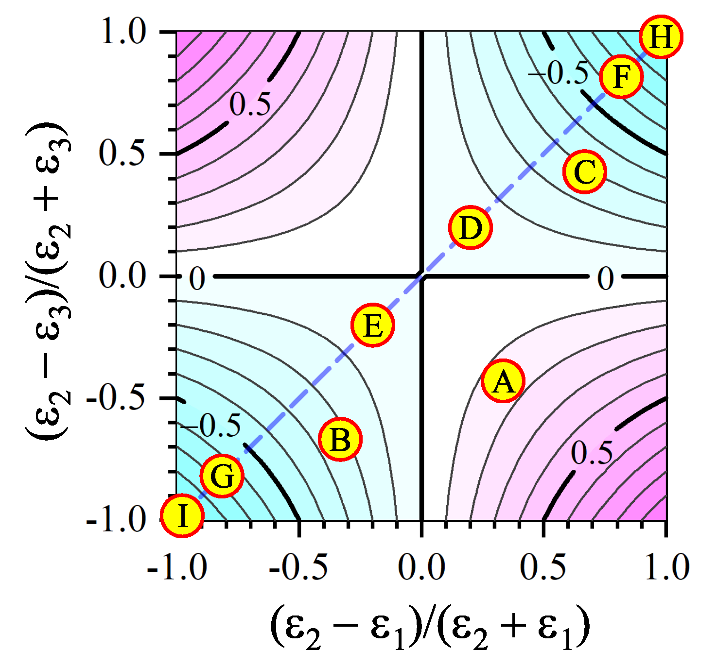
For three non-symmetric ( ε 1 ε 2 ε 3 ) structures with comparable ε i s (A–C), we chose layer dielectric constants equal to 1, 2, and 5 taken in various combinations. Those values were chosen to ensure that any value among Equations (15) and (18) does not coincide with another one. A value of 1.5 for symmetric ( ε 1 = ε 3 = ε and ε 2 = ε ) structures D and E was selected, because this ratio is typical of currently studied heterostructures [62,72,107,108,109,110]. Large values of 10 and 100 were taken for symmetric structures F to I following the seminal work by Keldysh [48], who discussed sandwiches containing polar solids with large dielectric constants. All ε sets mentioned in Table 1 are also indicated in Figure 2.

5. The Particular Case z = z . Series Calculations

In this and several following sections, we consider the case, when the both charges are located at the same vertical level ( z = z z ) in the three-layer system. Then, the normalized distance s between them (see Equation (56)) becomes equal to the parameter r, which describes their relative interval in the lateral plane (see Figure 1). Therefore, a quantity to be analyzed is the product r w .
Now, only three F i sets are relevant for the calculations:
  • for w 11 ( z 1 2 ) :
    F 1 = 1 ε 1 , F 2 = 1 ε 1 δ ¯ ( ε 2 , ε 1 ) exp q 2 z 1 , F 3 = 1 ε 1 δ ¯ ( ε 2 , ε 3 ) exp q 2 z + 1 , F 4 = 1 ε 1 δ ¯ ( ε 2 , ε 1 ) δ ¯ ( ε 2 , ε 3 ) exp 2 q ;
  • for w 22 ( 1 2 z 1 2 ) :
    F 1 = 1 ε 2 , F 2 = 1 ε 2 δ ¯ ( ε 2 , ε 1 ) exp q 2 z + 1 , F 3 = 1 ε 2 δ ¯ ( ε 2 , ε 3 ) exp q 2 z + 1 , F 4 = 1 ε 2 δ ¯ ( ε 2 , ε 1 ) δ ¯ ( ε 2 , ε 3 ) exp 2 q ;
  • for w 33 ( 1 2 z ) :
    F 1 = 1 ε 3 , F 2 = 1 ε 3 δ ¯ ( ε 2 , ε 1 ) exp q 2 z + 1 , F 3 = 1 ε 3 δ ¯ ( ε 2 , ε 3 ) exp q 2 z 1 , F 4 = 1 ε 3 δ ¯ ( ε 2 , ε 1 ) δ ¯ ( ε 2 , ε 3 ) exp 2 q .
In Figure 3, the calculation results obtained for the chosen three non-symmetric toy configurations are displayed. The presented pattern corresponds to a pair of charges separated by the spacing r and moving perpendicularly to the interfaces. The figure demonstrates that the interaction energy between the charges, if the distance r 0 , remains a continuous and smooth function, even when the charges cross either of the interfaces. However, this smoothness is a specific feature of the charge arrangement z = z . Otherwise, the polarization charges induced at the interface by a charge located near the interface would result in a cusp in the dependence w ( r , z z ) when the other charge crosses the interface. However, if z = z , there are no polarization charges at the interface at the moment when the both charges cross it simultaneously(!): the problem symmetry dictates that the electric field vectors at the interface must lie in the horizontal plane at this moment. Nevertheless, small remnants (or, better to say, precursors) of the indicated non-smoothness can be observed at small zs, i.e., when the charges are rather close to each other.
Strictly speaking, the realistic motion of charges perpendicularly to the interfaces should be considered making allowance for the change of the system’s total electrostatic energy. The latter, besides the energy of interaction between the charges, also includes the image force energy (self-energy). However, the charge motion across the interfaces presented here is virtual. Namely, below, we assume that the charge positions with respect to the interfaces is fixed ( z = const , z = const ), so that we are interested in the r-dependence of the charge–charge interaction energy w ( r ) . In this case, the variation of the image force energy does not matter, and the change in the total electrostatic energy is determined by that of w ( r ) .
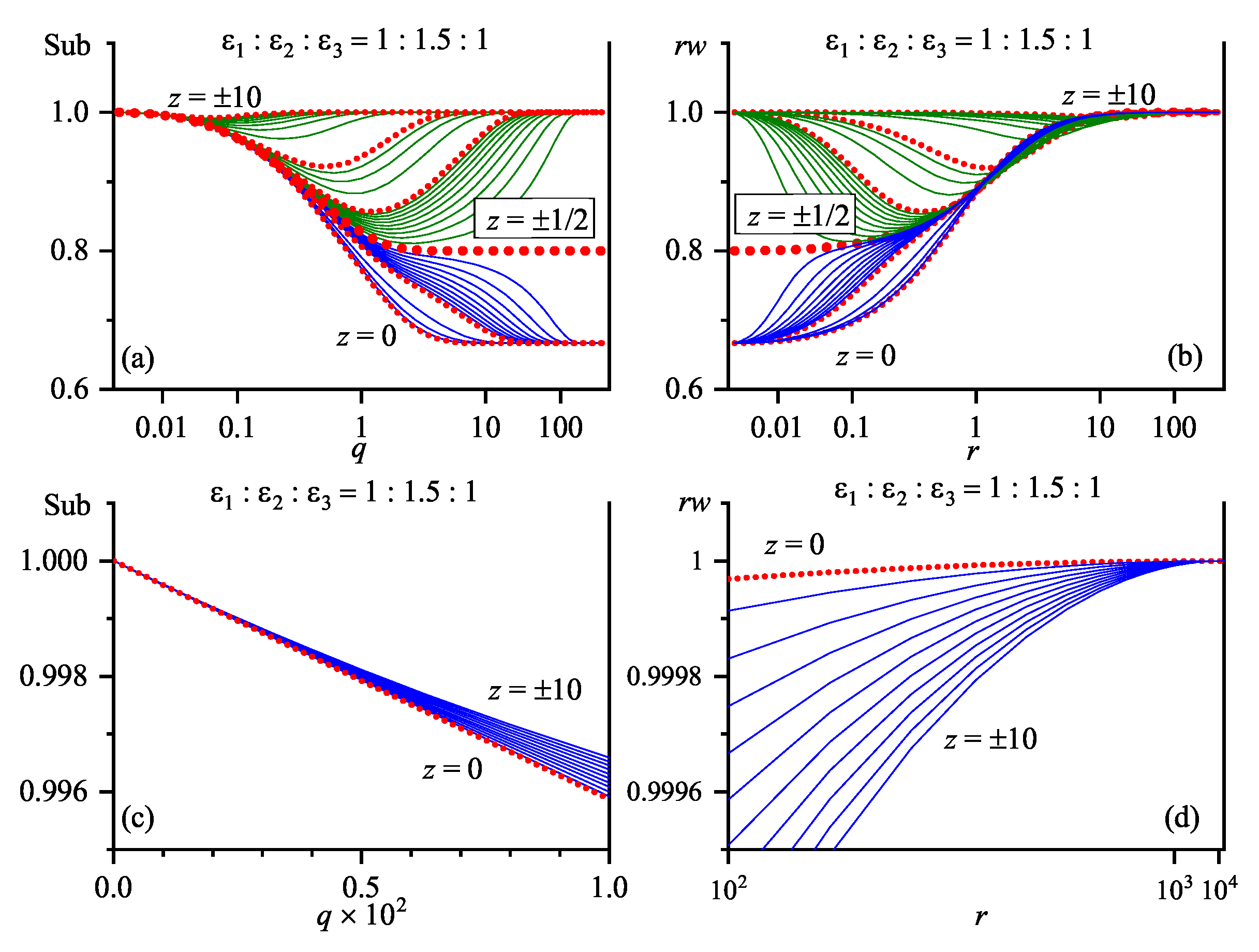
In Section 3, it is shown how the functions w ( r ) and Sub ( q ) are related by the Hankel transform (see Equation (3)). Figure 4 illustrates the corresponding pairs of functions r w ( r ) and Sub ( q ) in a wide interval of the charge coordinate z in toy structure A (this is a counterpart of Figure 3a). For this ε i combination, the depicted dependences do not overlap, but transform monotonically as z varies, which allows all typical features to be traced more or less clearly.
We draw attention to a close resemblance of the plots in Figure 4a,b. This similarity is true for the central section of the plots, being very useful, because it allows one to predict the behavior of the r w ( r ) (and, hence, w ( r ) (dependence at the qualitative level by considering Sub ( q ) without integration. Vice versa, one can judge about the behavior of Sub ( q ) on the basis of the dependence r w ( r ) . This property dictated by the Hankel transform relation [102,103] between w ( r ) and D ( q ) (see Equation (3)) will be used in the further analysis. However, as follows from Figure 4c,d, the functional dependences of Sub ( q ) on q at q 0 and r w ( r ) on 1 / r at r are different. Since r w ( r ) rather than Sub ( q ) is a matter of major concern, let us consider it in more detail.
The main features of the r w ( r ) dependence are as follows.
  • One can see that the quantity r w (in essence, the strength of the normalized Coulomb interaction in a three-layer system) strongly depends on z and r. This fact reflects the many-body character of the image forces [111,112] crucially distorting the parent electrostatic interaction in the inhomogeneous (in particular, layered) media.
  • For infinitesimally close charges located in the covers’ bulk, i.e., not near the interfaces, the product r w approaches the appropriate values ε i 1 that characterize the corresponding bulk media i. If the charges are at the interface between media i and j, this value equals 2 / ε i + ε j , as in much simpler two-layer structures [59]. Thus, when two infinitesimally close charges ( r 0 ) cross an interface ( z = ± 1 2 ) between media i and j, the value of the product r w changes in a step-like manner. To be more precise, it demonstrates two jumps: from ε i 1 to 2 / ε i + ε j and further to ε j 1 . (Note that such an analysis would be impossible for the “bare” (truly Coulombic) function w ( r ) possessing a conventional pole singularity at r 0 .) At r 0 , the product r w —and, hence, the function w ( r ) itself—changes smoothly [as was illustrated in Figure 3a. This transformation was considered in more detail in [59] for a two-layer system. The analysis remains valid for the three-layer system, because two infinitesimally close charges near either of the interfaces “cease to feel” the other interface (as was in the case of the charges in the bulk, where the specific Coulombic singularity “masks” all other interactions in the system), and the three-layer problem transforms into the two-layer one. In the vicinity of interfaces ( z = ± 1 2 ), we plotted the dependences r w ( r ) corresponding to various zs with a small step in order to illustrate how the smoothness of the dependence r w ( r 0 , z ) matches the jumps in the dependence r w ( r = 0 , z ) .
  • At r , all dependences tend to the same limit 2 / ε 1 + ε 3 (see Equation (16)). In terms of dimensional variables, the limit r corresponds to both R at a fixed L and L 0 at a fixed R. Since Z = z L , the latter interpretation can be regarded as a consequence of two processes: (i) the disappearance of the slab (we leave the ideal conductor case ε 2 = beyond the consideration), so that the three-layer system transforms into a two-layer one; and (ii) the deposition of both charges onto a single interface between two media (1 and 3). From the qualitative viewpoint, this limiting case means that there are no electric force lines in the slab.
  • Even for charges located in the depth of any medium, their interaction deviates from the “true” Coulombic dependence ( r 1 ) already at rather short distances from each other, i.e., the influence of other media matters.
Some of the r w -dependences are non-monotonic. However, we emphasize (see Equation (17)) that the quantity r w is only a coefficient in front of r 1 . The “bare” interaction energy w remains to be a monotonically decreasing function of r, because it has to satisfy the Laplace equation
Δ w = 0 ,
where Δ is the Laplace operator, in the bulk of each medium, since the polarization charges in heterostructures arise only at the interfaces.
The corresponding dependences for toy structures B and C have the same characteristic features. However, the curves in the relevant plots strongly intersect one another and can lead to a confusion. Therefore, those sets are not presented. However, the picture becomes monotonic again and convenient for analysis in the case of symmetric structures if we consider either of the symmetrical semi-spaces z 0 or z 0 . Figure 5 and Figure 6 illustrate the corresponding Sub - r w pairs, as well as their short-wave and long-range asymptotics, for various zs in toy structures D and E, respectively. One can see that the similarity between the curves in the pairs is not so clear, but it still exists. The main difference between the curves displayed in Figure 5 and Figure 6 and those depicted in Figure 4 consists in a drastic narrowing of the bundle of Sub ( q 0 ) asymptotics. Actually, the dependences Sub ( q ) have the same first q-derivative at q 0 . This fact has an important consequence and will be considered below in detail.
In our previous publication [59], we found that, in the case of a two-layer dispersionless systems with a given ratio ε 2 / ε 1 , all curves such as those presented in Figure 4a can be reduced to a single curve ε eff ( z ) . It is remarkable that this unique curve could be used not only to calculate the r-dependences of the interaction between two charges with z = z , but also the z-dependence for a charge pair with z = z for a fixed r. Now, the availability of the second interface and the new length parameter L makes the existence of a unique function ε eff ( z ) impossible.
Thus, the calculation of the integral in Equation (3) by expanding the denominator in its integrand in the parameter θ makes it possible to calculate the interaction between two charges with an accuracy set in advance (in most cases, we required a relative accuracy of 10 6 in series calculations). However, as was indicated above, the convergence rate of the series can be rather slow. The reason can be understood from Equation (11) and formulas for F i in Appendix C. In the case z = z , the functions f i ( z , z ) are either comparable with 1 (if they depend on the difference z z ) or with the sum z + z = 2 z . If r and z are small, both the factor ( θ ) j and the number 2 j in the denominator of Equation (11) have a substantial effect on the magnitude of the next series term. Otherwise, the effect of increasing 2 j is insignificant, and the convergence rate is almost solely determined by the parameter θ . Thus, we can describe the domain of slow convergence of the series in Equation (11) as
( r 1 and / or z 1 ) and θ 1 .
Hence, there arises a problem of constructing rather compact and accurate approximations that could be expressed in a finite analytical form.

6. Effective-Exponential Approximation

The main difficulty in calculating the integral in Equation (3) is the existence of the denominator in Equation (5) in its integrand, which incorporates multiple image reflections [15,27,106] and comprises the interface polarization contribution to the electrostatic interaction energy. While obtaining an expression that would represent integral (3) rather well in the whole interval r [ 0 , ) , the most trivial, but reasonable, idea consists in that the denominator should be replaced by a function that can fit it well, but allows analytical integration. The class of such functions is not wide. The following reasons have to be taken into account.
  • The function Den 1 ( q , ε ) changes monotonically from ( 1 + θ ) 1 at q = 0 to 1 at q = , and, as discussed above, it contains no singularities.
  • Since Equation (3) involves the Bessel function in the integrand, it is very important for the new function to satisfy the required asymptotics both at q 0 and q .
Therefore, we approximate the function Den 1 ( q , ε ) by the function
Inv ( q , ε ) = 1 θ 1 + θ exp ( 2 q a ) .
Note that this approximation, similar to Den 1 ( q , ε ) itself, does not include the z-coordinates of the charges, so that it remains valid in the general case z z . The parameter a is chosen to satisfy the equality
0 d q Den ( q , ε ) = 0 d q Inv ( q , ε ) .
The integrals on both sides are calculated analytically, and we arrive at the solution
a = θ 1 + θ ln 1 + θ .
Substituting the function in Equation (23) into Equation (3), we obtain
w ( z , z , r ; ε ) 0 d q J 0 ( q r ) Num ( q , z , z ; ε ) Inv ( q , ε ) = i A i 1 r 2 + f i ( z , z ) 2 θ 1 + θ 1 r 2 + f i ( z , z ) + 2 a 2 ,
where a is determined by Equation (24). Below, this approximation will be referred to as E0. Note that the sum in Equation (25) has a finite number of summands. It is remarkable that the final result can be obtained in the analytical form for any combination of problem parameters, i.e., the dielectric constants of the layers, the width of the inner layer L, the charge locations Z and Z , and the lateral distance between the charges R.
As an example, let us derive the approximation E0 for the interaction between two charges with z = z located in the interlayer. For this purpose, we should use the set in Equation (20) for w 22 . Accordingly, Equation (25) reads
w 1 2 z = z 1 2 , r ; ε 1 ε 2 1 r θ 1 + θ 1 r 2 + 2 a 2 + 1 ε 2 ε 2 ε 1 ε 2 + ε 1 1 r 2 + ( 2 z + 1 ) 2 θ 1 + θ 1 r 2 + ( 2 z + 1 ) + 2 a 2 + 1 ε 2 ε 2 ε 3 ε 3 + ε 2 1 r 2 + ( 2 z + 1 ) 2 θ 1 + θ 1 r 2 + ( 2 z + 1 ) + 2 a 2 + 1 ε 2 ε 2 ε 1 ε 2 + ε 1 ε 2 ε 3 ε 2 + ε 3 1 r 2 + 2 2 θ 1 + θ 1 r 2 + 2 + 2 a 2 ,
where a is described by Equation (24), and θ by Equation (6). The other variants are calculated similarly. Hence, the proposed approximation of the charge–charge interaction in a three-layer structure reduces to a simple algebra.
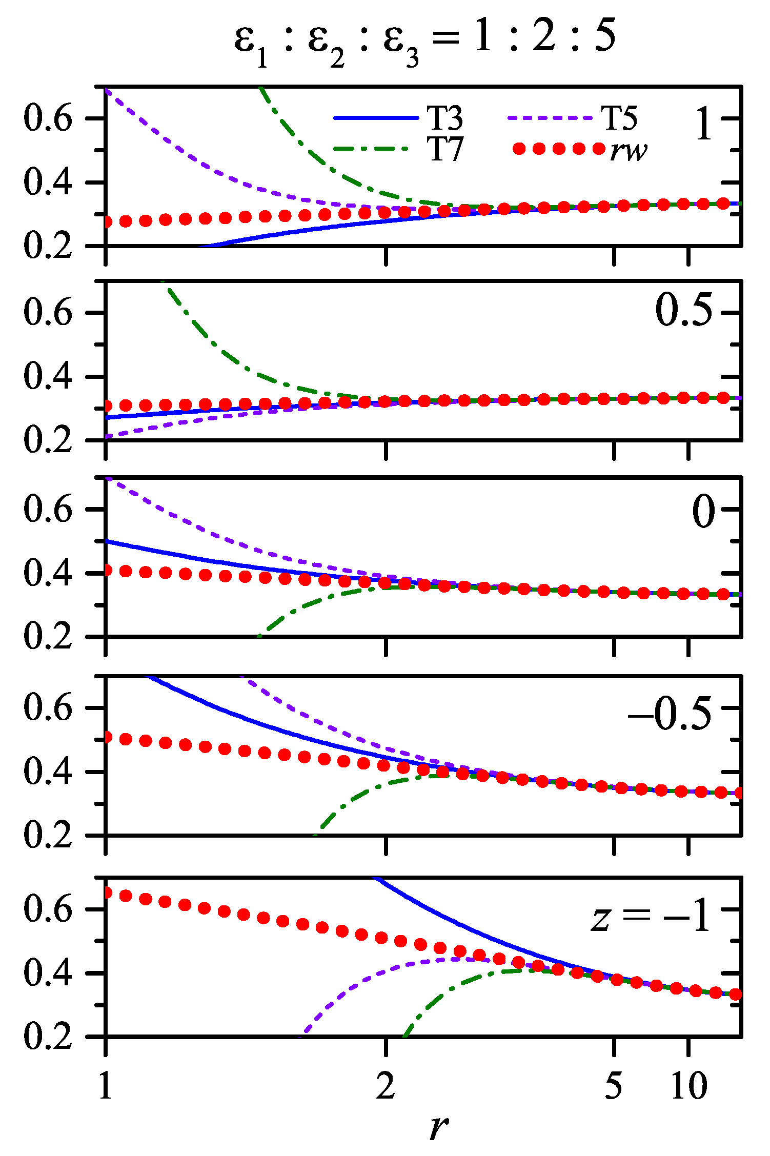
In Figure 7 (left), the results calculated using the series expansion (see Section 4) of Equation (3) and the analytical approximation in Equation (25) are shown for z = z and our toy structure B (the results for structures A and C are qualitatively similar). One can see that, at comparable ε i -values (corresponding to relatively moderate θ -magnitudes, see Table 1), our interpolation formula (the dashed curve) describes the behavior of the electrostatic interaction (the dotted curve) excellently within the whole r-interval [ 0 , ) for a wide range of the parameter z. The relevant curves are almost indistinguishable from each other, so that the right panels demonstrate the relative deviation of the E0 approximation from the exact r w ( r ) dependence (the dashed curves).
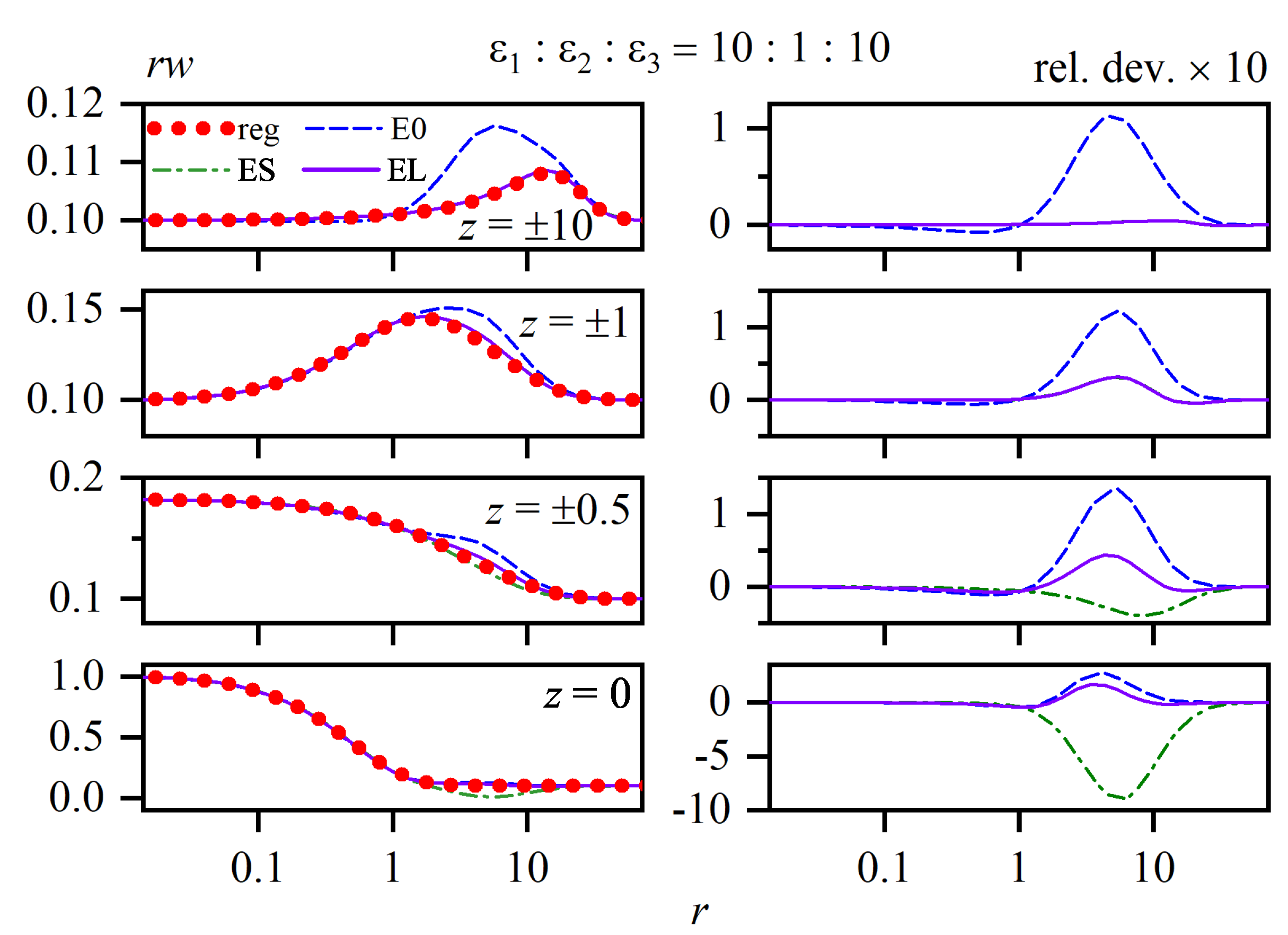
However, what about the domain of slow convergence in Equation (22)? Figure 8 and Figure 9 illustrate the results of corresponding calculations for symmetric toy structures D and E, respectively, in which the dielectric permittivity ε 2 of the interlayer differs rather strongly from that of the covers (see Table 1). One can see that the approximation (the dashed curves) is not so good as in the previous case. To elucidate this issue, we should analyze the approximation Inv ( q , ε ) in more detail.
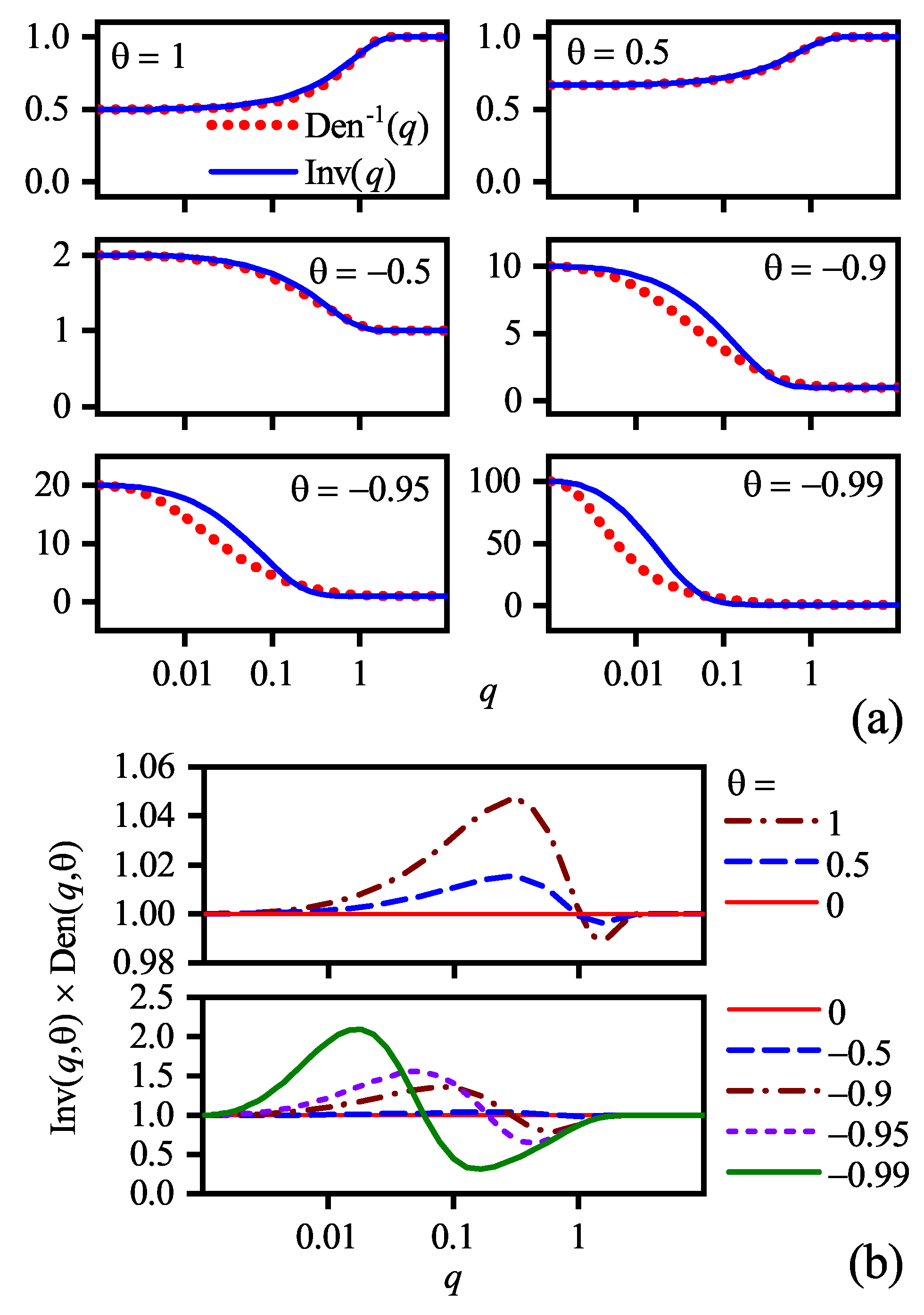
Actually, Inv ( q , ε ) is a function of q and θ . This is also true for its parent Den 1 ( q , ε ) . Figure 10a compares those two functions for several θ s, and Figure 10b demonstrates their ratio in the whole θ -interval. As long as θ 0.5 , the approximation is satisfactory. However, at θ 0.5 , the function Inv ( q , θ ) may strongly deviate from Den 1 ( q , θ ) , especially at small qs. In Appendix D, we show that, in the integral in Equation (3) with a large enough r, the Bessel function plays a role of a generalized δ -function, so that the interval of small qs makes the dominant contribution to this integral. In our opinion, just this situation emerges at θ 0.5 , so that Inv ( q , θ ) contributions that are “overestimated” at small qs distort the true value of the integral. Moreover, the situation can be even more complicated. The summands in the sum in Equation (7)—actually, they are exponential functions—may strongly compensate one another at small qs. In this case, a q-interval that is more distant from q = 0 , where the function Inv ( q , θ ) is “underestimated” (see Figure 10b), can insert the dominant contribution. Anyway, the final result will be unsatisfactory.
A receipt to overcome this difficulty was proposed in Section 3. In particular, we should integrate the leading term(s) analytically and regard the remainder as a correction (see Equation (13)). The latter should be approximated using, e.g., the method described in this section. More specifically, we used the procedure in Equation (13) to every ith term in the sum in Equation (7) for which f i ( z , z ) = 0 . The extracted terms were combined into a single pure Coulombic component and extracted into the Coulomb tail, whereas the remainders, together with other F i terms, were treated in the framework of the effective-exponential approximation considered in this section. In essence, this is a version of the power grouping procedure described in Section 4. The dash-dotted curves in Figure 8 demonstrate the results obtained for symmetric toy structure F following this method. It is evident that the application of the latter leads to a substantial improvement of final results.
We emphasize that it is worth doing the term grouping procedure in any case. For instance, in the case when the charges are in medium 3 (see the set F i in Equation (21)), one can see that F 1 + F 4 = 1 ε 3 Den ( q , θ ) , so that those terms produce a single and exact common contribution. At the same time, the terms F 2 and F 3 can be grouped. As a result, we obtain a single integral for the approximation.
If we consider the transformation of Equation (12) into Equation (13) more thoroughly, we understand that the grouping procedure applied to the terms with f i ( z , z ) = 0 is nothing but an extraction of the exact short-range ( r 0 ) asymptotics into the Coulomb tail. This approximation will be denoted as ES. However, in Figure 8, we had troubles with large r-distances. Therefore, there arises an idea to preliminarily extract the exact long-range ( r ) asymptotics. It is easy to understand that the corresponding coefficient equals Sub ( q = 0 ) . This approximation is denoted as EL, and its results are shown in Figure 8 by solid curves. Note that the ES and EL approximations coincide in the symmetric case if z > 1 2 , because the short- and long-range asymptotics are identical for the electrodes. The difference between those approximations in the whole interval of z-variation can be observed in Figure 7.
The same extraction procedure of different Coulombic asymptotics was also applied to symmetric toy structure G. The results obtained were found to be similarly satisfactory (see Figure 9). Thus, the extraction of either short- or long-range asymptotics improves, as a rule, the approximation accuracy. Nevertheless, the comparison of Figure 8 and Figure 9 testifies that the selection between those asymptotics must be done carefully. Again, no recommendation can be made a priori.
To summarize this section, the effective-exponential approximation is very simple and seems to be very useful and easily applicable in practice for estimating the behavior and magnitude of the interaction energy w ( z = z , r ) in heterostructures.

7. Long-Range Asymptotic Power Sums

The easiest way to fill the lacuna in the effective-exponential method is to construct a long-range asymptotics for the integral in Equation (3) in the form of asymptotic sums. Really, since the function Sub ( q , z , z ; ε ) does not depend on r, this integral belongs to the class of integrals in Equation (A33) considered in Appendix D. Therefore, we may evaluate its long-range ( r ) asymptotics using the properties of J 0 ( q r ) as a generalized δ -function. This means that only the properties of the function Sub ( q , z , z ; ε ) at small qs are relevant. Hence, we should first expand the Subintegrand into a Taylor power series in q,
Sub ( q , z , z ; ε ) = i = 0 q i i ! d i d q i Sub ( q , z , z ; ε ) q = 0 .
Then, every term in the expansion should be integrated with J 0 ( q r ) using equations of Appendix D. As a result, we obtain an asymptotic series of the type
w ( z , z , r ; ε ) odd i 1 N a a i r i .
which contains only odd powers of r. The coefficients as in the expansion in Equation (28) depend on the problem parameter set, which, in our case, includes the dielectric permittivities of the media and the z , z -coordinates of the charges, and does not depend (at i N a ) on N a .
The analytical results obtained for a i can be obtained straightforwardly, but they are rather cumbersome. Therefore, as an example, we present the approximation formula for w ( z = z , r ; ε ) only in the case when the both charges are located in the interlayer ( 1 2 z = z 1 2 ), and retain only the first two terms: i = 1 and 3 (this approximation are denoted as T3):
w ( z , z , r ; ε ) = a 1 r + a 3 r 3 + O 1 r 5 ,
where
a 1 = 2 ε 1 + ε 3
and
a 3 = 1 2 ε 1 + ε 3 3 ε 2 2 × 4 ε 3 z + 1 2 2 ε 1 3 + 2 4 z 2 1 ε 3 2 4 ε 2 2 z 3 2 z + 1 2 ε 1 2 8 ε 3 1 2 z 1 2 2 ε 3 2 + ε 2 2 z 2 + 1 4 ε 1 4 ε 2 2 z 2 + z 3 4 ε 3 2 + ε 2 2 .
The complexity of expressions for the higher-order coefficients increases drastically with their order numbers. Nevertheless, they remain to be ordinary algebraic expressions similar to those presented above.
One should note that the coefficient a 1 is z-independent, as it has to be (see Equation (16)), whereas the coefficient a 3 is a quadratic polynomial of z including the non-zero linear z-term. However, in the symmetric geometry ( ε 1 = ε 3 = ε , ε 2 = ε ),
a 3 = ε 2 ε 2 4 ε 3 4 ε 2 ε 2 z 2 + 1 ,
and the linear z-term disappears, which is important for further consideration.
In Section 5, we emphasize an unambiguous relation between the Sub ( q ) and w ( r ) functions. In particular, this concerns a relation between the short-wave asymptotics Sub ( q 0 ) and the long-range asymptotics w ( r ) (see the relevant panels in Figure 4; in the case of symmetric structures, see Figure 5 and Figure 6). Here is a corresponding short-wave counterpart of the long-rang asymptotics in Equation (29):
Sub ( q , z , z ; ε ) = b 0 + b 1 q + b 2 q 2 + O ( q 3 ) ,
where
b 0 = 2 ε 1 + ε 3 , b 1 = 2 ε 1 2 z 2 ε 3 2 z + ε 1 2 2 ε 2 2 + ε 3 2 ε 2 ε 1 + ε 3 2 , b 2 = 1 2 ε 1 + ε 3 3 ε 2 2 × 4 z 2 ε 1 2 ε 2 2 + 8 z 2 ε 1 2 ε 3 2 8 z 2 ε 1 ε 2 2 ε 3 + 4 z 2 ε 1 ε 3 3 4 z 2 ε 2 2 ε 3 2 + 4 z ε 1 3 ε 3 + + 4 z ε 1 2 ε 2 2 4 z ε 1 ε 3 3 4 z ε 2 2 ε 3 2 + ε 1 3 ε 3 + 3 ε 1 2 ε 2 2 2 ε 1 2 ε 3 2 2 ε 1 ε 2 2 ε 3 + ε 1 ε 3 3 4 ε 2 4 + 3 ε 2 2 ε 3 2 .
In the symmetric geometry ( ε 1 = ε 3 = ε , ε 2 = ε ),
b 0 = 1 ε , b 1 = ε 2 ε 2 2 ε 2 ε ,
b 2 = ε 2 ε 2 4 ε 3 4 ε 2 ε 2 z 2 + 1 .
A correlation between those two sets of formulas is obvious. The latter set explains the collapse of the divergent bunch of the Sub ( q ) curves for various zs in the case of non-symmetric structures (see Figure 4c) into a narrow bunch of the corresponding curves divergent only in the second derivative in the case of symmetric structures (see Figure 5c and Figure 6c).
In Figure 11, the exact long-range w ( r ) profiles (dotted curves) calculated for toy structure A are compared with their asymptotic sums (Equation (28)) calculated for N a = 3 , 5 , 7 at certain characteristic z-values. We selected this structure with comparable ε s to demonstrate that the long-range asymptotics of w really depend on z, although weakly. One can see that the lower end of the convergence interval for the sums in Equation (28) becomes larger as the charges go farther from the slab (the parameter z increases by magnitude). It is also evident that the further ( N a > 3 ) expansion of the series in Equation (29) is not required for qualitative calculations.
However, again, what about the domain of slow convergence of the regular method, where the effective-exponential approximation is not efficient? Figure 12 demonstrates that the method of long-range asymptotic power sums resolves, to some extent, this problem. However, the corresponding interval where the sum approximates the dependence w ( r ) can be not enough to cover the interval where the effective-exponential method works badly.
Figure 11 and Figure 12 also illustrate the following fact. For any finite N a , the sum in Equation (28) is divergent at r 0 . Therefore, the w ( r ) profile is very sensitive to the values of the expansion coefficients a i . In the case of comparable ε i s, the change of z modifies those coefficients quite enough for this modification to appreciably affect the sum profiles in Figure 11. This fact confirms the validity of Equation (32). In the case ε ε , the z-dependent term prevails in the multiplier a 3 , and small variations in the long-range behavior of the dependence w ( z ) can be observed (Figure 12a). However, if ε ε , the validity of the expansion in Equation (29) is universal but less satisfactory than in the opposite case ε ε (Figure 12b).
Attention should be paid that the asymptotic series in Equation (29), as well as the omitted terms in it, was obtained directly from the integral in Equation (3) without any approximations. Therefore, this series is exact and can serve as a reference to verify the quality of various approximate expressions, at least in the long-range limit.

8. Rytova–Keldysh Approximation and Its Modification

8.1. Preliminary Remarks

The Rytova–Keldysh approximation (RKA) for the electrostatic interaction in three-layered structures was for the first time suggested and analyzed by Rytova while studying the screened potential of a point charge in a slab [113] and later on by Keldysh (in a slightly different approach) for the charge–charge interaction in the same geometry [48]. However, both authors analyzed the interaction between two charges located at different sides of the slab, so that the z-coordinates of the charges were fixed ( z = 1 2 and z = 1 2 in our notation), and the interaction energy w was z-independent. The concrete results obtained in those articles [48,113] are often applied to a number of charge configurations without specifying them and applying the RKA formula mostly to exciton physics in heterostructures [68,72,73,76,77,78,98,101,114,115,116,117,118,119].
In Section 9, we consider Coulomb interaction in the configuration z = 1 2 and z = 1 2 in more detail. At the same time, in this section, we analyze how the RKA can be modified to include the z-coordinates of the charges into consideration, which is necessary, in particular, to improve the numerical results. In this connection, we would like to emphasize that under the term “Rytova–Keldysh approximation”, we mean an analytical approximate method used to calculate integrals such as that in Equation (3) rather than a particular solution of the charge–charge interaction problem in the specific configuration z = 1 2 and z = 1 2 .
The following circumstances have to be taken into account. In essence, the RKA was developed to calculate the long-range asymptotics of the integral in Equation (3). It is based on the property of the Bessel function J 0 ( x ) to play the role of a generalized δ -function (see Appendix D). Then, if we are interested in the long-range asymptotics of the integral in Equation (3), the task of approximating the profiles of Subintegrand Sub ( q ) in the whole interval 0 q < , which are rather complicated (see, e.g., the relevant panels in Figure 4, Figure 5 and Figure 6), becomes not urgent. Now, we have to choose such an approximation for Sub ( q ) that (i) the resulting formula be integrable analytically, and (ii) the approximation be accurate enough at small qs.
Formally, the RKA is a two-parametric approximation of the function Sub ( q ) in the vicinity of q = 0 selected in the form
Sub ( q ) A q + D .
Hence, we need two independent quantities (conditions) to determine the parameters A and D. Among such quantities, the most natural are the values of the function Sub ( q = 0 ) and its derivative d d q Sub ( q = 0 ) . All other possible sets of two independent parameters must be related to this one. However, for a system with a given set ε i , the value (see Equation (33))
Sub ( q = 0 ) = 2 ε 1 + ε 3
and, thus, the ratio A / D , is fixed (see Equation (15)). Therefore, the derivative value d d q Sub ( q = 0 ) acquires an extremely important significance.
The approximation in Equation (36) is applicable only if D > 0 . In this case, Equation (3) is integrable analytically (see Equation (A41)), and the approximation formula for w ( r ) looks like (see Equation (A41))
w ( r ) A π 2 H 0 ( r D ) Y 0 ( r D ) .
It has a logarithmic singularity at r 0 instead of the proper pole one [68,101]. Therefore, it can never be applied to calculate the short-range w ( r ) -asymptotics, although the r-interval of its applicability can be rather wide for some ε i sets and z-values.

8.2. RK0 Approximation and Its Modifications

In the basic RKA version (we refer to it as RK0), the numerator Num ( q ) in Sub ( q ) (see Equation (4)) is substituted by its value at q = 0 , whereas the denominator Den ( q ) is approximated by a linearized Taylor series in q. After the corresponding normalization of the numerator and denominator, we arrive at Equation (36), where
A = 2 ε 2 ε 2 ε 3 ε 2 + ε 1 , D = θ + 1 2 θ = ε 1 + ε 3 ε 2 ε 2 ε 3 ε 2 + ε 1 .
These parameters ensure both the correct value of the fraction in Equation (36) at q 0 and its vanishing at q . One should note that all information about the position of charges (z and z ) was contained in the numerator Num ( q ) , and hence it is lost altogether in the RK0 approximation. As was indicated above, this assumption was sufficient for the original approximation to be applicable in the across-slab configuration of charges in the layered system [48,113] (see also Section 9).
For the right hand side in Equation (36) to have no singularity at q 0 (i.e., D > 0 ), the parameter θ must be negative, i.e., 1 < θ < 0 . This condition is realized if ε 2 > max ( ε 1 , ε 3 ) or ε 2 < min ( ε 1 , ε 3 ) , so that toy structure A becomes excluded from consideration at once. However, this condition is always valid for symmetric ( ε 1 = ε 3 ) heterostructures. In any case, since the RK0 approximation is a monotonously decreasing q-function (therefore, its derivative at q = 0 is always negative), it will result in a monotonously increasing r-asymptotics.
For the other toy structure C, the corresponding dashed curve in Figure 13a demonstrates that the RK0 approximation is too rough to provide reliable results except for very large r, which is no wonder, because RK0 was constructed to describe this limit. As is evident from Equation (39), both parameters A and D are fixed, so that the RK0 profile is also constant and cannot trace the variation of the r w ( r ) -profile with z (the dotted curve). The situation is even worse for toy structure B (Figure 13b), because the RK0 and r w profiles disperse in different directions from the asymptotic point. Indeed, the actual derivative d d q Sub ( q = 0 ) is positive here.
Hence, we have to modify Equation (36) and approximate the derivative d d q Sub ( q = 0 ) in such a way that it would improve the fitting of the original Sub ( q ) dependence. In so doing, we are not allowed to change the linear binomial in the denominator, because more complicated functions will make the integral in Equation (3) non-integrable analytically. Instead, we may try to expand the numerator Num ( q ) (see Equation (4)) into a Taylor series. In the case of linear expansion, it is easy to see that, after simplification, the approximating function can be now written in the form (the approximation RK1)
Sub ( q ) A q + D + B .
where D is the same as in the approximation in Equation (36), i.e., it is given by Equation (39), but A and B are determined on the basis of the both values Sub ( q = 0 ) and d d q Sub ( q = 0 ) . The variation of the parameter B corresponds to the shift of dependence (36) along the ordinate axis, so that now we can reproduce dependences with positive d d q Sub ( q = 0 ) : for this purpose, A must be negative and B positive and large enough. The actual values of the parameters A and B in the geometry z = z are as follows:
A = 2 ε 2 2 + z + 1 / 2 ε 1 2 z 1 / 2 ε 3 2 ε 2 ε 2 ε 3 2 ε 2 + ε 1 2 , B = 2 z ε 1 + 2 z ε 3 ε 1 + 2 ε 2 ε 3 ε 2 ε 3 ε 2 + ε 1 .
One can see that, in the symmetric configuration ( ε 1 = ε 3 ), the both parameters become z-independent. Of course, the latter fact follows from the z-independence of the derivative d d q Sub ( q = 0 ) . This is illustrated by Figure 5c and Figure 6c, as well as by Equation (32). The latter also testifies that we have to expand the numerator Num ( q ) up to the second-order term to ensure that the approximate Sub ( q ) and, hence, r w ( r ) depend on z. After a straightforward simplification, we obtain (the approximation RK2)
Sub ( q ) A q + D + B + C q .
The parameter D , as expected, remains the same, but new expressions for the parameters A, B, and C are cumbersome, and their explicit formulas are omitted here. Every term in the RK2 approximation multiplied by the Bessel function J 0 ( q r ) is integrable.
The following circumstance is of interest. The coefficients in the series expansion of Num ( q ) for given z and z do not depend on the expansion order. However, when Sub ( q ) is transformed to the forms containing the RK term (Equation (36)), the parameters, firstly A and then B, change from one approximation to the other. The expressions for A and B in the approximation in Equation (42) differ strongly from Equation (41) for the approximation in Equation (40). At the same time (see Equation (A37)), the last term in Equation (42) does not contribute by no means to the r w -dependence, although the Subintegrand approximation does change! It looks as if the role of this term consists in a proper renormalization of the coefficients in the approximation in Equation (40).
All the aforesaid is illustrated in Figure 13. One can see that the account of the next terms in the series expansion of Num ( q ) strongly improves the approximation quality. This is especially true for toy structure B (Figure 13b), for which the behavior of the basic RK0 approximation is totally wrong.

8.3. Original RKA

Let us pay attention that Equation (36) has an extremely felicitous property. If the { ε i } -driven parameter θ tends to 1 , the singularity point q = θ + 1 2 θ < 0 approaches zero. As a result, the contribution to the integral in Equation (3) from the vicinity of the left-end point q = 0 increases and, at θ s sufficiently close to 1 , becomes dominating. The limit θ 1 is realized in two cases: (i) ε 2 min ( ε 1 , ε 3 ) ; and (ii) ε 2 max ( ε 1 , ε 3 ) . As noted in the previous section (see also Equation (34)), the derivative d d q Sub ( q = 0 ) is negative in the former case, so that it must be excluded from consideration.
Let us take symmetric structures ( ε 1 = ε 3 = ε , ε 2 = ε ) to illustrate this scenario. In this case, the parameters A and D in Equation (36) look like
A = 2 ε ε ε 2 , D = 2 ε ε ε ε 2 .
We recall that the results of the approximation in Equation (36), which was used to calculate long-range asymptotics, remain to be z-independent. This model is satisfactory at large ε / ε ratios. Indeed, even for toy structure D with ε i = 1 : 1.5 : 1 , the profile of the dependence Sub ( q ) near q = 0 changes weakly for various zs [see Figure 5c; note that the curves in that figure span the z-coordinate values z 10 , whereas the slab is located at z 1 2 ]. In the case of toy structure F with ε i = 1 : 10 : 1 , this change is much weaker according to Equation (35). Therefore, the calculations in this section can be considered as those made for the charges located, e.g., near the middle of the slab ( z = z 0 ).
Figure 14 illustrates the quality of the RK0 approximation for various values of the ratio ε / ε > 1 (cf. the dotted and dashed curves). A drastic improvement of the RK0 approximation with the increase of ε / ε is obvious. It is worth noting that this improvement takes place in a wide interval of r-values rather than only at r 1 . Nevertheless, as was indicated above and is illustrated in the inset of the bottom panel in Figure 14, the difference between the logarithmic (appropriate to RKA) and pole (genuine Coulombic) singularities at r 0 survives at any ε / ε -ratio, so that this approximation cannot be applied if one is interested in the electrostatic interaction behavior at very short distances between the charges.
Thus, one can see that two factors—large θ -magnitudes ( θ 1 ) and the property of the Bessel function J 0 ( q r ) to play the role of δ ( q ) -function in integrals of the type in Equation (3) at large rs—“work cooperatively” to achieve the same goal: to allow the close vicinity of q = 0 , where substitution of Equation (36) is justified, to make a dominant contribution to the integral in Equation (3). If either of those conditions is not met, the other can compensate the absence of its counterpart by becoming stronger.
Keldysh [48] made a next step and, in accordance with the relationship ε 2 max ( ε 1 , ε 3 ) , coarsened the parameters A and D (Equation (39)):
A A c = 2 ε 2 , D D c = ε 1 + ε 3 ε 2 ,
or, in the symmetric case,
A c = 2 ε , D c = 2 ε ε .
We refer to this approximation as RKorg. Amazingly, but in most cases, the “coarsened” RKorg approximation turns out to be more successful than the seemingly “more accurate” RK0 one (see the solid curves in Figure 14)! Moreover, this is also true for non-symmetric structures with comparable ε i s. In a good many cases, the RKorg approximation turns out to be even more accurate than the corresponding RK2 one (see Figure 13a). Of course, this is true only if the RKorg approximation is applicable (see Figure 13b).
To explain this fact at the present stage of discussion, let us recall that the quality of the approximation in Equation (36) is determined not least by its derivative value at q = 0 . In Figure 15, the ratios of the derivatives d d q RK 0 ( q = 0 ) and d d q RKorg ( q = 0 ) to the actual derivative d d q Sub ( q = 0 ) are compared with each other. There is no doubt that the RKorg approximation wins the competition.
Moreover, let us rewrite the RKorg approximation in the form
A c q + D c = A c q + D q + D c q + D ,
whence it becomes evident that it corresponds to a fractionally rational (homographic) approximation to Num ( q ) . The capabilities of functions belonging to this class strongly exceed the capabilities of Taylor series. In particular, fractionally rational functions are used to approximate complicated special functions to a high accuracy within rather wide intervals (see, e.g., [120,121]).

8.4. Fitting Approximations

The success of the RKorg approximation with the coarsened parameters in Equation (44) or Equation (45) brought us to the following idea. In essence, the coarsening procedure detached the original physical meaning from the quantities A and D. We propose to go further. Namely, let us declare them fitting parameters and use the values of both Sub ( q = 0 ) and d d q Sub ( q = 0 ) to determine them. As an example, we obtain (the approximation F0)
A = 4 ε 2 2 z + 1 ε 1 2 + 2 z + 1 ε 3 2 2 ε 2 2 , D = 2 ε 2 ε 1 + ε 3 2 z + 1 ε 1 2 + 2 z + 1 ε 3 2 2 ε 2 2
for charges located in the slab ( 1 2 < z < 1 2 ), and
A = 2 ε 3 ε 2 z 1 / 2 ε 1 2 ε 3 2 ε 2 + ε 1 2 ε 2 2 ε 3 , D = ε 3 ε 2 ε 1 + ε 3 z 1 / 2 ε 1 2 ε 3 2 ε 2 + ε 1 2 ε 2 2 ε 3
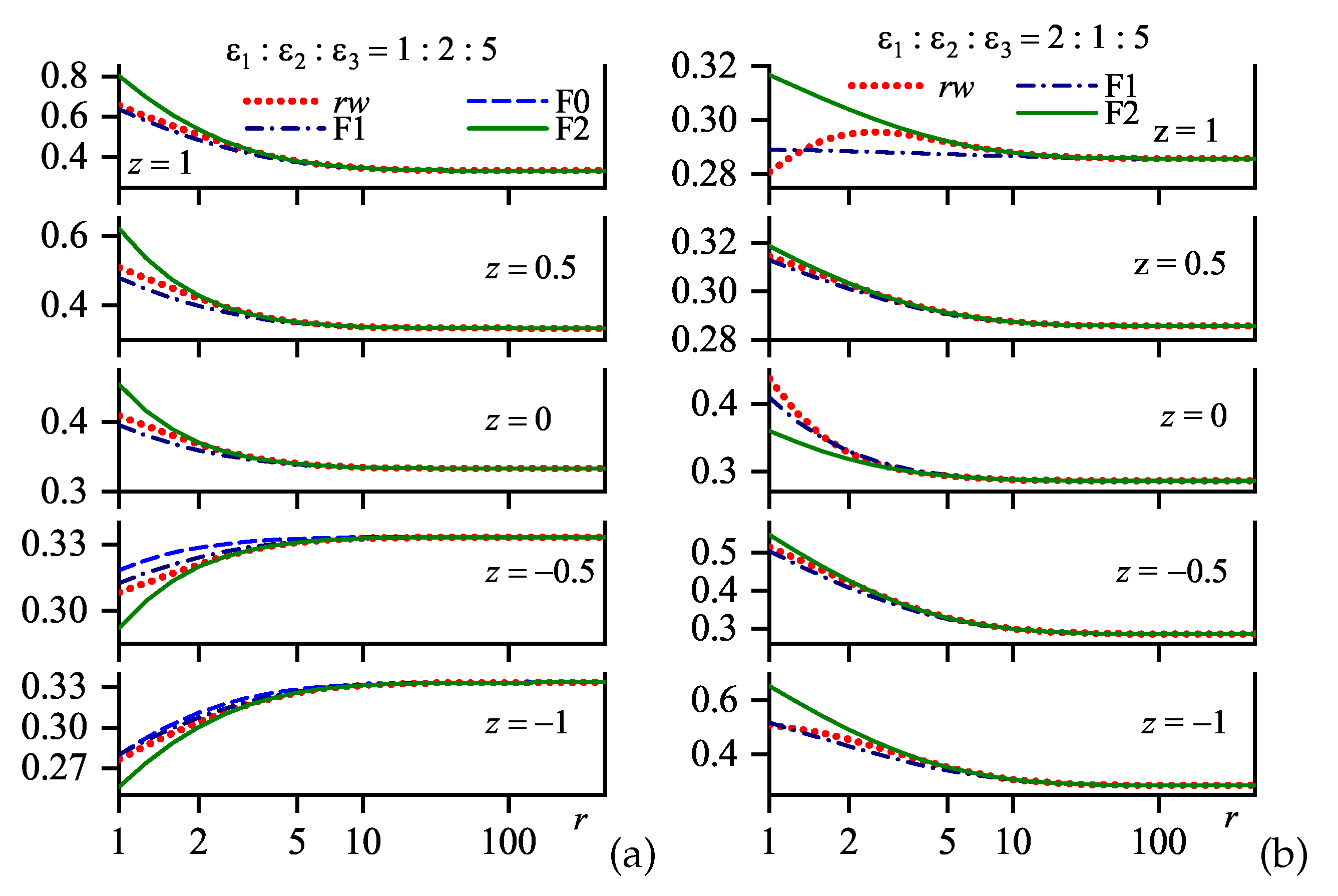
if they are in medium 3 ( z 1 2 ). The analytical formulas for the coefficients in the models in Equations (40) (the approximation F1) and (42) (the approximation F2) are very cumbersome algebraic expressions and are not shown. Attention should be paid that now every approximation requires an extra condition, i.e., additional information about Sub ( q ) . In particular, for the approximation F2, it is necessary to know the expressions for Sub ( q = 0 ) and d i d q i Sub ( q = 0 ) with i = 1 to 3. One can see that the fitted values depend on z even in the lowest approximation, but (as expected) only for non-symmetric structures. Since the denominator of the parameter D depends on z, it, in principle, can change its sign. Therefore, the sought approximation may exist only in definite z-intervals. At the same time, the emerged z-dependence of the coefficients A and D can make the fitting F0, F1, and F2 approximations applicable for those ε i sets (again, within definite z-intervals), where their non-fitting counterparts fail.
Figure 16 demonstrates the results of calculations for toy structures A, B, and C with comparable ε i s. The results testify to a good quality of fitting approximations, which allows them to be used down to very short distances between the charges. The results obtained for toy structures D and E are even better and, hence, are not displayed. At the same time, there are no F0 plots in some panels, which means that this model failed for the corresponding parameter sets.
Now, we can explain the success of the RKorg approximation from a more general viewpoint. This approximation is an intermediate point on the way from the initial, primitive RK0 approximation to its more complicated fitting extension. Keldysh made a partial correction, which is, generally speaking, necessary for the influence of the Num ( q ) dependence on the overall behavior of w ( r ) to be taken into account. Maybe he was lucky to guess “coarsening” approximation (44) leading to the description improvement, because the coarsening corrects the “theoretically accurate” coefficients in Equation (39) in the proper direction.

8.5. Remarks on the Margin

We have paid so much attention to the RKA, because it is used rather often in recent studies of heterostructures [73,98,101,114,115,116,117,118,119], although sometimes beyond the scope of its applicability [122]. This approximation was considered as an auxiliary tool with respect to the effective-exponential approximation (Section 6) in the domains of problem parameters, where the latter approximation gives unsatisfactory results. Both approaches can be used in combination to check the results obtained in the framework of other approximations. Their compatibility follows from the complete equivalence of their long-range asymptotics (irrespective of the RKA versions, except for the RKorg with its coarsened parameters (Equation (45))) obtained to an arbitrary order, both with each other and with those obtained in the exact method of long-range asymptotic power sums (Section 7). However, the RKA is rather cumbersome, and totally fails in the very important case of heterostructures with close values of dielectric constants [62,63,66,108,109,110,122]. Therefore, the effective-exponential approximation is preferable, as a rule. Moreover, one should never use any version of the Rytova–Keldysh approximation to study the interaction of charges at short distances, r 1 .

9. The Case z = 1 2 , z = 1 2 . Coulombic Interaction across the Interlayer

9.1. Preliminary Remarks and Analytical Formulas

For many fundamental and practical problems [65,66,73,84,123], it is important to elucidate how two point-like charges interact with each other if they are located at different interfaces of the slab in the three-layer system. The interaction of charges through a slab is of special interest for the problems of exciton spectra in heterostructures [48,67,68,69,70,71,72,73,74,75,77,78,119] as well as those concerning exciton (electron–hole) superfluidity in layered systems [46,47,79,80,81,82,83,84,85,86] and related topics [75,123,124,125,126]. In some of those works, the actual electron–hole interaction was considered to be a conventional Coulombic attraction, whatever the relationship between the dielectric permittivities of the media involved. Meanwhile, any proper analysis of the electron–hole pairing must include a detailed account of the electrostatic interaction screening by all three layers. That is why a number of attempts were made to describe, more or less correctly, the charge–charge interaction as applied to the indicated phenomena [11,48,70,113]. However, in the problems concerned, the RKorg approximation (Equation (45)) was and remains the most popular theoretical foundation of calculations.
Broadly speaking, the spatial dispersion of ε i ( k ) should be taken into account, especially if itinerant charge carriers are present. Of course, the corresponding results will be cumbersome and less transparent. Therefore, since the problem has not been analyzed even in the adopted here simplest possible CDP model, we believe that it is worthwhile obtaining an insight in the framework of the classic electrostatic approach. Hence, a firm basis should be developed in order to check the validity of the existing simplifications in the framework of the theoretical scheme (Equations (A1)–(A24)).
As indicated above, the required F i set can be obtained from any of the sets for w 12 , w 13 , w 22 , and w 23 (see Appendix C) by putting z = 1 2 and z = 1 2 in them. Let us use the set in Equation (A29) as the simplest of them (it includes only one term). Substituting Equation (A29) into Equation (3), we see that the interaction of charges located in the both outer layers is “the true Coulombic one” only if θ = 0 , i.e., if ε 2 equals either ε 1 or ε 3 , or, in other words, if the system is two-layer (or one-layer if ε 1 = ε 2 = ε 3 ). When θ 0 , we have
w 13 z 1 2 , z 1 2 = 4 ε 2 ε 3 + ε 2 ε 1 + ε 2 0 d q J 0 ( q r ) exp q 2 + z z 1 + θ exp 2 q .
Below, we consider the most interesting, from the practical viewpoint, symmetric case ( ε 1 = ε 3 ε ε 2 = ε ). Then, the parameter θ becomes
θ = ε ε ε + ε 2
and, together with the denominator in Equation (5), does not depend on the interchange ε ε . As a result (see Equation (3)), we obtain an interesting symmetry relation for the interaction between two point charges located in different cover layers of the studied heterostructure:
w z 1 2 , z 1 2 , r ; ε 1 = ε 3 = ε , ε 2 = ε w z 1 2 , z 1 2 , r ; ε 1 = ε 3 = ε , ε 2 = ε = ε ε .
Of course, this relation is valid in the limiting case z = 1 2 , z = 1 2 as well. In particular, Equation (3) acquires the form
w = 4 ε ε + ε 2 0 d q J 0 ( q r ) exp q 1 + θ exp 2 q 4 ε I ε + ε 2 ,
which is evidently consistent with the relationship in Equation (51). The integral I in Equation (52) can be calculated analytically if the charges are arranged vertically ( r = 0 ). The result is as follows:
I = 1 2 θ ln 1 + θ 1 θ if θ < 0 , 1 θ arctan θ if θ > 0 .
In the symmetric case, which is considered in this section, θ < 0 , and we obtain
w 13 z = 1 2 , z = 1 2 , r = 0 = 2 ε ε 2 ε 2 ln ε ε .
The simplest variant of the effective-exponential method (the approximation E0, Section 6), when being applied to the calculation of the integral I in Equation (52), gives the following simple approximate formula for the charge interaction:
w 13 z = 1 2 , z = 1 2 , r = 4 ε ε + ε 2 1 r 2 + 1 θ 1 + θ 1 r 2 + 1 + 2 a 2 ,
where a is determined by Equation (24).
Another circumstance consists in that now the normalized distance between the charges equals (see Equation (1))
s = r 2 + 1 .
However, the lateral distance r is more interesting from the experimental viewpoint, in particular, when studying a possibility and features of the excitonic superfluidity [47,79,80,81]. Therefore, we take r as the main argument of the interaction energy w ( r ) . At the same time, the charges do not approach each other closer than the slab thickness, and their interaction energy has no singularities at r 0 . As a result, the application of the product r w leads to the convergence of all r w ( r ) curves into a single point at r 0 , which is inconvenient for the analysis. The use of the product s w allows getting rid of this shortcoming. Furthermore, the product s w complies with the sense of the parameter C considered in the previous sections (see Equation (17)). Therefore, just this quantity is selected for further examination.
In the long-range limit and for an arbitrary ratio between ε and ε , the application of the RK0 to Equation (52) leads to the following result:
w 13 RK 0 z = 1 2 , z = 1 2 , r π ε ε ε 2 H 0 2 r ε ε ε ε 2 N 0 2 r ε ε ε ε 2 .
This formula has the Coulombic asymptotics r 1 at r , but logarithmically diverges at r 0 (see, e.g., [68,101]). Of course, Equation (57) satisfies the symmetry relationship (51).
Keldysh’s coarsening (Equation (45)) of Equation (57) at ε ε leads to the result of [48],
w 13 RKorg z = 1 2 , z = 1 2 , r π ε H 0 2 r ε ε N 0 2 r ε ε ( ε ε ) .
Note that symmetry relation (Equation (51)) becomes violated in this case. However, a formula similar to Equation (58) can be obtained in the opposite limit ε ε by interchanging ε ε .
It is remarkable that, in the Thomas–Fermi approximation for the two-dimensional electron gas, the charge–charge Coulomb interaction in thin metal films or semiconductor surface inversion layers has a form similar to Equation (57) [127,128]. A comparison of those two formulas demonstrates that now, in the CDP approximation, the quantity ε ε 2 / ( 2 ε ε ) plays the role of dimensionless (normalized by the slab thickness L) screening radius [114,118,126].

9.2. Results of Calculations

Let us proceed from the calculation of Subintegrand. According to Equation (49), it is equal to
Sub ( q ) = 4 ε 2 ε 3 + ε 2 ε 1 + ε 2 × exp q 1 + θ exp 2 q .
Its Taylor series up to the linear term equals
Sub ( q ) 2 ε 1 + ε 3 2 ε 1 ε 3 + ε 2 2 ε 2 ε 1 + ε 3 2 q + O ( q 2 ) .
One can see that the derivative d d q Sub ( q = 0 ) is always negative, so that the RK approximation is also valid, at least formally. Note that Keldysh overlooked this possibility, having assumed that his approximation is valid only if ε 2 > max ( ε 1 , ε 3 ) . We emphasize that the last statement concerns only the specific configuration of charges located at different interfaces.
In Figure 17, the dependences Sub ( q ) are shown for all toy structures. The analysis of the curves presented in this figure and the calculation results for the w ( r ) dependences that are discussed below completely confirm conclusions made in the previous sections on the validity domain of each examined approximation. In particular, this concerns the mutually complementary character of the effective-exponential and RK approximations. From the viewpoint of their applicability, the former works excellently in a wide range of problem parameters, except for large r and incomparable ε values in tandem; the latter works as if it were specially designed to fill this lacuna.
The curves in Figure 17 look very similar: a monotonic, quite rapid (exponential) reduction to zero at q . Therefore, we may confine the analysis only to the symmetric configuration. Moreover, since in this case, the relationship in Equation (51) takes place, we consider only configurations with ε 2 > ε 1 = ε 3 .
Figure 18 illustrates the results of calculations for toy structure D ( ε i = 1 : 1.5 : 1 ) using the regular series expansion method expounded in Section 3 (the dotted curve) and the E0 approximation in Equation (55) (solid curve). One can hardly detect the difference between the curves, because the relative approximation error does not exceed 1.4 × 10 4 in the whole interval 0 r < . The extraction of the long-range asymptotics (the approximation EL) allows this error to be reduced to 5.9 × 10 5 . Note that the isolation of the short-range asymptotics (the approximation ES) has no sense in this case, because the charges do not approach each other closer than the slab width.
Owing to the relationship in Equation (51), the w ( r ) profile for toy structure E ( ε i = 1.5 : 1 : 1.5 ) can be obtained from Figure 18 by changing the ordinate axis scale. The approximation error values remain the same.
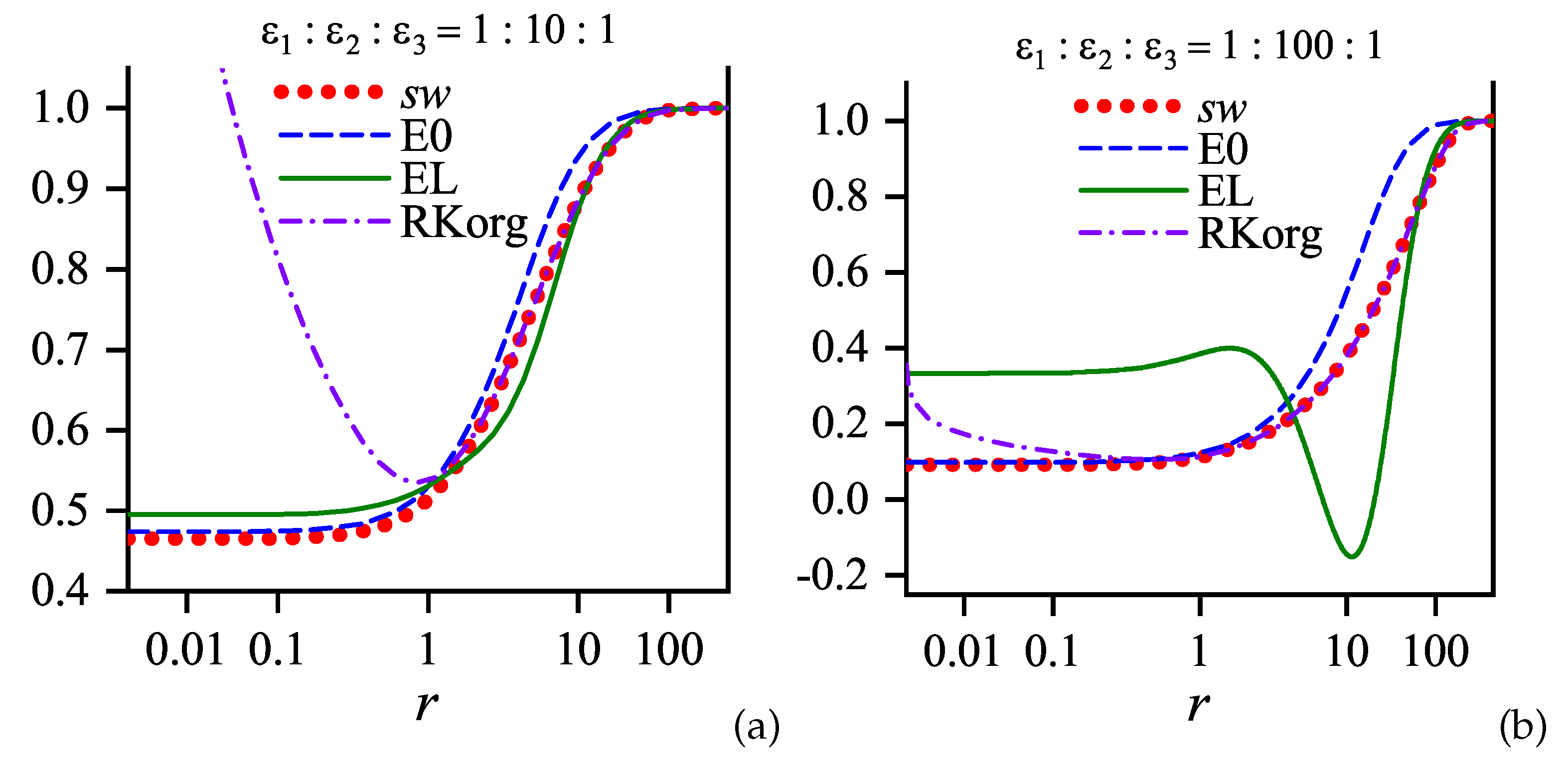
The picture becomes more complicated if the difference between the dielectric constants in the slab and covers is large. As indicated in Section 6, the effective-exponential approximation cannot provide sufficient accuracy at large inter-charge distances in this case and should be appended, e.g., by the RKorg approximation. In Figure 19a, we demonstrate such a combination for toy structure F ( ε i = 1 : 10 : 1 ).
An even more pronounced example of this “cooperation” is illustrated in Figure 19b for toy structure H with a very large difference between the dielectric constants in the slab and covers ( ε i = 1 : 100 : 1 ). One can see that the seemingly “more accurate” EL approximation can produce a physically unreasonable result (the negative static dielectric constant). At the same time, the E0 and RKorg approximations provide an almost smooth approximation of the r w ( r ) dependence with a high accuracy in the whole approximation interval 0 r < .
Our calculations clearly demonstrate that, e.g., in the exciton physics of heterostructures [48,67,68,69,70,71,72,73,74,75,76,77,78,98,101,114,115,116,117,119], where the dielectric permittivities of the media are usually of comparable values, it is better to use our effective-exponential approach rather than any version of the RKA. Nevertheless, the latter might turn out successful for some parameter sets, although those approximations are not at all universal (in particular, they contain an inevitable logarithmic singularity at small arguments). Furthermore, the effective-exponential approximation is attractive owing to its simplicity and convenience, because the specific approximate expressions for w ( s ) are algebraic ones.

10. Conclusions

In this work, we calculated the charge–charge electrostatic interaction W in a three-layer structure with plane interfaces. Exact formulas for the dependence of W on the relative lateral, R, and perpendicular with respect to the interfaces, Z and Z , coordinates of the charges were presented. In the framework of the simplest approach, where the dielectric functions of the media were treated as dispersionless constants, simple approximations allowing finite analytical expressions were derived and discussed. They allow one to obtain an insight into the problem, as well as to use them in practical applications, at least for estimation purposes. The results obtained can serve as reference ones when developing the theory further. The results found in the framework of different approximations were compared and analyzed.
Two specific charge arrangements were analyzed in detail. This is the case when the Z-coordinates of the charges are identical ( Z = Z ) and when the charges are located at different interfaces. It was shown that the Rytova–Keldysh approximation (RKA) [48,113], which is widely used, e.g., in the physics of excitons [73,74,76,101,114,115,125,129,130], turns out to be unsatisfactory in heterostructures with similar dielectric constants of the media involved. Instead, we proposed a new analytical approximate formula (the effective-exponential approximation) that fits well the exact integrals [6,11,15] in a wide range of their parameters. The spectrum of applications of the proposed theory can be rather wide. For instance, it can be used in the studies of possible electron–hole superfluidity in layered structures [46,47,79,80,81,82,83,84,85,86].

Author Contributions

A.M.G. and A.I.V. conceived and designed the work.

Funding

This research was partially supported by the National Academy of Sciences of Ukraine (Grants Nos. 1.4.B-179, VC-188, and VC-202) and by the Project No. 22 of the 2018–2020 Scientific Cooperation Agreement between Poland and Ukraine.

Acknowledgments

We are grateful to Mai Suan Li and Henryk Szymczak (Institute of Physics of the Polish Academy of Sciences, Warsaw, Poland) for helpful discussion.

Conflicts of Interest

The authors declare no conflict of interest. This research received no external funding.

Abbreviations

The following abbreviations are used in this manuscript:
CDPconstant-dielectric-permittivity
RKARytova–Keldysh approximation

Appendix A. General Formulas for a Three-Layer System

In this appendix, the length, charge, and momentum parameters are dimensional quantities.
The explicit expressions describing the charge–charge interaction energy W Q Q ( S ) between two point-like charges Q and Q located in a three-layer system consisting of two semi-infinite homogeneous media 1 ( Z < 0 ) and 3 ( Z > L ) separated by a homogeneous media 2 ( 0 < Z < L )—each of the ith medium ( i = 1 , 2 , 3 ) is characterized by the dielectric permittivity function ε i ( k , ω ) —can be found using several equivalent approaches [6,11,14,15] based on the assumptions of the infinite interface barriers for particles forming the media involved, the specular reflection of the charge carriers at the corresponding interfaces, and the absence of relativistic retardation effects that take into account the finiteness of the light velocity [131,132,133,134,135]. In particular, the energy W Q Q ( S ) can be written in the form
W i j ( R , Z , Z ) = 2 Q Q 0 q d q D i j q , Z , Z J 0 ( q R ) ,
where the subscripts i and j denote the media where the charges Q and Q , respectively, are located; R is the horizontal distance between the charges; Z and Z are their vertical coordinates; and J 0 ( x ) is the Bessel function of the first kind. The functions
D i j = A i ( Z ) B j ( Z ) + A ˜ i ( Z ) B ˜ j ( Z ) C F i ( Z , Z ) δ i j ,
where δ i j is the Kronecker delta, are called Green’s functions of the three-layer Coulomb problem [1]. They describe the screened electrostatic interaction and allow both the charge–charge interaction and the self-energy of the charge in the layered system (the image charge energy [6,11,15]) to be calculated.
In the reference frame described above, the auxiliary quantities entering Equation (A2) are as follows:
A 1 ( Z ) = A ˜ 1 ( Z ) = a 1 ( Z ) ,
A 2 ( Z ) = a S ( Z ) , A ˜ 2 ( Z ) = a A ( Z ) ,
A 3 ( Z ) = A ˜ 3 ( Z ) = a 3 ( Z L ) ,
B 1 ( Z ) = a 1 ( Z ) a A ( 0 ) + a 3 ( 0 ) ,
B ˜ 1 ( Z ) = a 1 ( Z ) a S ( 0 ) + a 3 ( 0 ) ,
B 2 ( Z ) = 1 2 a S ( Z ) + a A ( Z ) a A ( 0 ) + a 3 ( 0 ) + a S ( Z ) a A ( Z ) a A ( 0 ) + a 1 ( 0 ) ,
B ˜ 2 ( Z ) = 1 2 a S ( Z ) + a A ( Z ) a S ( 0 ) + a 3 ( 0 ) a S ( Z ) a A ( Z ) a S ( 0 ) + a 1 ( 0 ) ,
B 3 ( Z ) = a 3 ( Z L ) a A ( 0 ) + a 1 ( 0 ) ,
B ˜ 3 ( Z ) = a 3 ( Z L ) a S ( 0 ) + a 1 ( 0 ) ,
C = a S ( 0 ) + a 1 ( 0 ) a A ( 0 ) + a 3 ( 0 ) + a S ( 0 ) + a 3 ( 0 ) a A ( 0 ) + a 1 ( 0 ) ,
F 1 ( Z , Z ) = b 1 ( Z , Z ) ,
F 2 ( Z , Z ) = 1 2 b S ( Z , Z ) + b A ( Z , Z ) ,
F 3 ( Z , Z ) = b 3 ( Z , Z ) ,
where
a 1 , 3 ( Z ) = 1 π + d k cos k Z k 2 + q 2 ε 1 , 3 ( q , k , ω ) ,
a S , A ( Z ) = 2 L k S , A exp i k Z k 2 + q 2 ε 2 ( q , k , ω ) ,
k S = 2 n π L , k A = 2 n + 1 π L n = 0 , ± 1 , ± 2 , ,
b 1 ( Z , Z ) = 1 2 a 1 ( Z + Z ) + a 1 ( Z Z ) ,
b S , A ( Z , Z ) = 1 2 a S , A ( Z + Z ) + a S , A ( Z Z ) ,
b 3 ( Z , Z ) = 1 2 a 3 ( Z L + Z L ) + a 3 ( Z L Z L ) .

Appendix Approximation of Dispersionless Dielectric Permittivities

Equations (A1)–(A21) allow one to obtain electrostatic interactions between arbitrarily located charges in a three-layer structure made of arbitrary materials. Hereafter, in accordance with the aforesaid, we confine the consideration to the simplest possible case of the dispersionless ε i ( q , k , ω ) ε i = const in all three media. This approximation is valid not only for the universal “medium” —vacuum—but also for insulators and semiconductors with large band gaps. Although the approximation concerned seems trivial at first glance, we noticed that even this case has not been examined in the literature in full. In this approximation, we arrive at the three-constant ( ε i ) parameterization of the problem, and the quantities a 1 , S , A , 3 ( Z ) can be integrated analytically:
a 1 , 3 ( Z ) = 1 ε 1 , 3 q exp q Z ,
a S ( 0 Z L ) = 1 q ε 2 cosh q L 2 1 2 Z L sinh q L 2 ,
a A ( 0 Z L ) = 1 q ε 2 sinh q L 2 1 2 Z L cosh q L 2 .
If the argument Z goes beyond the indicated limits, the functions a S , A ( Z ) are recalculated according to the formulas
a S ( Z ) = a S ( Z ± L ) ,
a A ( Z ) = a A ( Z ± L ) .

Appendix B. Parameter θ

The parameter
θ = ε 1 ε 2 ε 1 + ε 2 × ε 2 ε 3 ε 3 + ε 2
plays a key role in the described theory. In particular, it governs the convergence rate of the series used to calculate the dependence w ( r ) . Besides that, it is responsible for the applicability of the RK approximation for w ( r ) at r .
Since in the framework of the classical electrostatics [106] all the dielectric constants entering the block in Equation (6) are positive (we note that it is not at all the case when the spatial dispersion of the dielectric permittivity is taken into account [136]), it is convenient to evaluate θ in terms of the relative differences between the relevant arguments. For instance, for the quantities x and y, the relative difference equals
δ ¯ ( x , y ) = x y x + y .
It varies from 1 at x y to + 1 at x y and equals zero at x = y . In some sense, this function is inverse to the Kronecker delta δ i j : the latter equals unity if its arguments are equal to each other, and becomes zero otherwise. Therefore, we use a bar in the notation to emphasize this difference.
In terms of the function δ ¯ ( x , y ) , the parameter θ looks like
θ = δ ¯ ( ε 2 , ε 1 ) δ ¯ ( ε 2 , ε 3 ) .
The contour plot of θ in the coordinate frame δ ¯ ( ε 2 , ε 1 ) vs. δ ¯ ( ε 2 , ε 3 ) is shown in Figure 2. It is evident that θ = 0 if either ε 2 = ε 1 or ε 2 = ε 3 . In those cases, we deal with a two-layer system. The case θ > 0 is realized if either ε 1 < ε 2 < ε 3 or ε 1 > ε 2 > ε 3 . The limiting case θ 1 takes place if either ε 1 ε 2 ε 3 or ε 1 ε 2 ε 3 , which seems rather improbable from the materials science viewpoint. Note that, if one of the latter conditions is weakened—e.g., ε 1 < ε 2 ε 3 —the parameter θ deviates from unity rather strongly to provide a good convergence of the w ( r ) -series for every r.
If ε 2 > max ε 1 , ε 3 or ε 2 < min ε 1 , ε 3 , the parameter is negative, θ < 0 . This is a practically important case. In particular, it is always realized in symmetric three-layer configurations with ε 1 = ε 3 = ε and any ε 2 = ε different from this value:
θ = δ ¯ 2 ( ε , ε ) .
The limiting case θ 1 takes place if either ε 2 ε 1 , ε 3 or ε 2 ε 1 , ε 3 , which can occur in many layered structures. For instance, those inequalities can be realized in sandwiches involving metals or ferroelectrics.

Appendix C. Constituents of Interaction Energy w(z,z′)

In this appendix, we present full sets of summands in the sum in Equation (7) that are required to calculate the interaction energy between two point-like charges in the three-layer system concerned. In particular, these are (we use the notation δ ¯ ( x , y ) for the relative difference, which was defined in Appendix B):
  • for w 11 ( z z 1 2 ) : N = 4 ,
    F 1 = 1 ε 1 exp q z z , F 2 = 1 ε 1 δ ¯ ( ε 2 , ε 1 ) exp q z z 1 , F 3 = 1 ε 1 δ ¯ ( ε 2 , ε 3 ) exp q z z + 1 , F 4 = 1 ε 1 δ ¯ ( ε 2 , ε 1 ) δ ¯ ( ε 2 , ε 3 ) exp q z z + 2 ;
  • for w 12 ( z 1 2 z 1 2 ) : N = 2 ,
    F 1 = 2 ε 1 + ε 2 exp q z z , F 2 = 2 ε 1 + ε 2 δ ¯ ( ε 2 , ε 3 ) exp q z z + 1 ;
  • for w 13 ( z 1 2 , z 1 2 ) : N = 1 ,
    F 1 = 4 ε 2 ε 1 + ε 2 ε 2 + ε 3 exp q z z ;
  • for w 22 ( 1 2 z z 1 2 ) : N = 4 ,
    F 1 = 1 ε 2 exp q z z , F 2 = 1 ε 2 δ ¯ ( ε 2 , ε 1 ) exp q z + z + 1 , F 3 = 1 ε 2 δ ¯ ( ε 2 , ε 3 ) exp q z z + 1 , F 4 = 1 ε 2 δ ¯ ( ε 2 , ε 1 ) δ ¯ ( ε 2 , ε 3 ) exp q z z + 2 ;
  • for w 23 ( 1 / 2 z 1 / 2 z ) : N = 2 ,
    F 1 = 2 ε 2 + ε 3 exp q z z , F 2 = 2 ε 2 + ε 3 δ ¯ ( ε 2 , ε 3 ) exp q z + z + 1 ;
  • for w 33 ( 1 2 z z ) : N = 4 ,
    F 1 = 1 ε 3 exp q z z , F 2 = 1 ε 3 δ ¯ ( ε 2 , ε 1 ) exp q z + z + 1 , F 3 = 1 ε 3 δ ¯ ( ε 2 , ε 3 ) exp q z + z 1 , F 4 = 1 ε 3 δ ¯ ( ε 2 , ε 1 ) δ ¯ ( ε 2 , ε 3 ) exp q z + z + 2 .
To avoid ambiguities but without any loss of generality, we confine ourselves to the case where the coordinate z of the charge in medium i does not exceed the coordinate z of the charge in medium j. It is evident that, due to the symmetry of the problem itself and the reference frame, the set for w 23 can be derived from the set for w 12 and the set for w 33 from the set for w 11 if one makes the obvious changes of indices.
All sets match in the corresponding limiting cases. For instance, the set for two charges that are located at different interfaces can be obtained from the sets for w 12 , w 13 , and w 22 by putting z 1 / 2 and z 1 / 2 . Summation of the obtained terms brings us to the same result in each case.

Appendix D. Integrals with the Bessel Function J0(q)
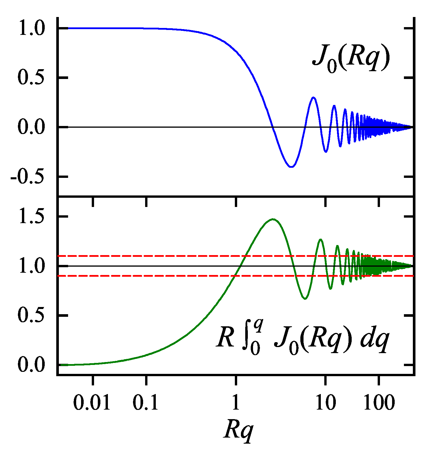
Let us consider the integral
w ( r , a ) = 0 d q J 0 ( q r ) G ( q , a ) ,
where a stands for a certain parameter set (it does not include the coordinate r), and G is a smooth enough and finite function, so that this integral converges. However, the set of G-functions for which the integral in Equation (A33) can be calculated analytically is rather restricted [137].
The quality of the approximate calculation of this integral is associated with the behavior of the Bessel function J 0 ( x ) , which is illustrated in Figure A1. The lower panel demonstrates that, if we take a relative accuracy of, e.g., ± 10 % and G ( q , a ) = const , the main contribution to the integral is given by the interval r q [ 0 , 60 ] . At r = 1 , this interval corresponds to the interval q = [ 0 , 60 ] in the integral in Equation (A1). Extending the upper integration limit beyond 60 will only provide a more accurate value within the selected error interval. Now, if the parameter r increases, say to 10, the interval r q = [ 0 , 60 ] will correspond to q = [ 0 , 6 ] in the integral in Equation (A1). In this sense, the Bessel function J 0 ( q r ) at r behaves as a generalized δ -function, making relevant only the dependence of the function G ( q , a ) at small qs.
Figure A1. The Bessel function J 0 ( x ) (top) and its normalized integral (bottom) as functions of the argument R q . The dashed lines in the lower panel indicate the 10%-error interval of the exact integral value. See explanations in the text.
Condensedmatter 04 00044 g0a1
Of course, the estimations made above are rough. They strongly depend on the behavior of the function G ( q , A ) . In particular, at G ( q , A ) 0 , the role of J 0 ( q r ) as a generalized δ -function will be more effective. At the same time, if G ( q , A ) vanishes at q 0 , the upper integration limit has to be selected as large enough. Anyway, if the integral in Equation (A33) converges, we may calculate its long-range ( r ) asymptotics taking into account the behavior of the function G ( q , a ) in the vicinity of q = 0 .
In this work, the formula [138]
I ( r , n , a ) = 0 d q J 0 ( q r ) q n exp ( a q ) = ( 1 ) n d n d a n 1 r 2 + a 2
is actively used. In particular, at n = 0 , we have
I ( r , 0 , a ) = 0 d q J 0 ( q r ) exp ( a q ) = 1 r 2 + a 2 ,
and, at a = 0 , the functions for various ns are:
I ( r , 0 , 0 ) = q 1 ,
I ( r , 1 , 0 ) = 0 ,
I ( r , 2 , 0 ) = q 3 ,
I ( r , 3 , 0 ) = 0 ,
I ( r , 4 , 0 ) = 9 q 5 , .
Note, that all values of I ( r , n , a ) with odd ns equal zero.
Another well-known integral used in this work looks like [138]
0 d q J 0 ( q r ) q + a = π 2 H 0 ( r a ) Y 0 ( r a ) ,
where the both real-valued parameters r and a are positive ( r > 0 and a > 0 ), and H 0 and Y 0 are the Struve and Neumann functions of the zeroth order, respectively. It is remarkable that similar expressions are typical of the polarization energy in the interface region if the spatial dispersion of dielectric permittivities is accounted for [139,140].
The property of the Bessel function J 0 ( q r ) to reduce the effective integration interval in Equation (A33) is essential for the Rytova–Keldysh approximation to work (see Section 8). At the same time, it can worsen the results obtained in the framework of the effective-exponential method (see Section 6).

References

  1. Romanov, Y.A. Theory of characteristic energy losses in thin films. J. Exp. Theor. Phys. 1964, 47, 2119–2133. [Google Scholar]
  2. Pashitskii, E.A.; Romanov, Y.A. Plasma waves and superconductivity in quantizing semiconducting (semimetallic) films and layered structures. Ukr. Fiz. Zh. 1970, 15, 1594–1606. [Google Scholar]
  3. Gabovich, A.M.; Pashitskii, E.A.; Uvarova, S.K. Plasmon and exciton superconductivity mechanism in layered structures. Fizika Nizkikh Temperatur 1975, 1, 984–995. [Google Scholar]
  4. Kornyshev, A.A.; Rubinshtein, A.I.; Vorotyntsev, M.A. Image potential near a dielectric-plasma-like medium interface. Phys. Status Solidi B 1977, 84, 125–132. [Google Scholar] [CrossRef]
  5. Gabovich, A.M.; Il’chenko, L.G.; Pashitskii, E.A. Electrostatic charge interaction with surfaces of metals and semiconductors. Fiz. Tverd. Tela 1979, 21, 1683–1689. [Google Scholar]
  6. Gabovich, A.M.; Il’chenko, L.G.; Pashitskii, E.A.; Romanov, Y.A. Electrostatic energy and screened charge interaction near the surface of metals with different Fermi surface shape. Surf. Sci. 1980, 94, 179–203. [Google Scholar] [CrossRef]
  7. Il’chenko, L.G.; Pashitskii, E.A.; Romanov, Y.A. Electrostatic charge potential in layered systems with spatial dispersion. Fiz. Tverd. Tela 1980, 22, 2700–2710. [Google Scholar]
  8. Il’chenko, L.G.; Pashitskii, E.A.; Romanov, Y.A. Charge interaction in layered systems. Fiz. Tverd. Tela 1980, 22, 3395–3401. [Google Scholar]
  9. Gabovich, A.M.; Il’chenko, L.G.; Pashitskii, E.A. Energy spectrum of electrons above a thin liquid helium film in a clamping electrical field. J. Exp. Theor. Phys. 1981, 81, 2063–2069. [Google Scholar]
  10. Kornyshev, A.A.; Vorotyntsev, M.A.; Ulstrup, J. The effect of spatial dispersion of the dielectric permittivity on the capacitance of thin insulating films: non-linear dependence of the inverse capacitance on film thickness. Thin Solid Films 1981, 75, 105–118. [Google Scholar] [CrossRef]
  11. Il’chenko, L.G.; Pashitskii, E.A.; Romanov, Y.A. Charge interaction in layered systems with spatial dispersion. Surf. Sci. 1982, 121, 375–395. [Google Scholar] [CrossRef]
  12. Gabovich, A.M.; Il’chenko, L.G.; Pashitskii, E.A. Image force and electron spectrum at the surface of liquid helium. Surf. Sci. 1983, 130, 373–394. [Google Scholar] [CrossRef]
  13. Gabovich, A.M.; Rozenbaum, V.M. Image forces and quantum states in semiconductor heterostructures. Fiz. Tekhn. Polup. 1984, 18, 498–501. [Google Scholar]
  14. Bechstedt, F.; Enderlein, R. Dielectric screening, polar phonons, and longitudinal electronic excitations of quantum well double heterostructures. Application to light scattering from charge density fluctuations. Phys. Status Solidi B 1985, 131, 53–66. [Google Scholar] [CrossRef]
  15. Gabovich, A.M.; Rozenbaum, V.M.; Voitenko, A.I. Dynamical image forces in three-layer systems and field emission. Surf. Sci. 1987, 186, 523–549. [Google Scholar] [CrossRef]
  16. Pokatilov, E.P.; Fomin, V.M.; Beril, S.I. Oscillatory Excitations, Polarons and Excitons in Multilayer Systems and Superlattices; Shtiintsa: Kishinev, Moldova, 1990. [Google Scholar]
  17. Pokatilov, E.P.; Beril, S.I.; Semenovskaya, N.N.; Fahood, M. Charge carrier energy spectrum in multi-layer structures and superlattices in the field of the self-action potential. Phys. Status Solidi B 1990, 158, 165–174. [Google Scholar] [CrossRef]
  18. Wendler, L.; Hartwig, B. The effect of the image potential on the binding energy of hydrogenic impurities in semiconductor quantum wells. J. Phys. Condens. Matter 1990, 2, 8847–8852. [Google Scholar] [CrossRef]
  19. Wendler, L.; Bechstedt, F.; Fiedler, M. Quasi-two-dimensional screening of the electron-hole interaction in modulation-doped quantum wells. Phys. Status Solidi B 1990, 159, 143–154. [Google Scholar] [CrossRef]
  20. Bah, M.L.; Akjouj, A.; Dobrzynski, L. Response functions in layered dielectric media. Surf. Sci. Rep. 1992, 16, 95–131. [Google Scholar] [CrossRef]
  21. Voitenko, A.I.; Gabovich, A.M.; Rozenbaum, V.M. Dynamic image forces and tunneling in three-layer systems. Fiz. Nizk. Temp. 1996, 22, 86–98. [Google Scholar]
  22. Basko, D.; La Rocca, G.C.; Bassani, F.; Agranovich, V.M. Förster energy transfer from a semiconductor quantum well to an organic material overlayer. Eur. Phys. J. B 1999, 8, 353–362. [Google Scholar] [CrossRef]
  23. Gabovich, A.M.; Reznikov, Y.A.; Voitenko, A.I. Excess nonspecific Coulomb ion adsorption at the metal electrode/electrolyte solution interface: Role of the surface layer. Phys. Rev. E 2006, 73, 021606. [Google Scholar] [CrossRef] [PubMed]
  24. Kovalev, V.M.; Chaplik, A.V. Screening effects and Friedel oscillations in quantum-well nanostructures. J. Exp. Theor. Phys. 2008, 134, 980–987. [Google Scholar] [CrossRef]
  25. Slater, J.C. The electronic structure of metals. Rev. Mod. Phys. 1934, 6, 209–280. [Google Scholar] [CrossRef]
  26. Herring, C.; Nichols, M.H. Thermionic emission. Rev. Mod. Phys. 1949, 21, 185–270. [Google Scholar] [CrossRef]
  27. Jennings, P.J.; Jones, R.O. Beyond the method of images – the interaction of charged particles with real surfaces. Adv. Phys. 1988, 37, 341–358. [Google Scholar] [CrossRef]
  28. Kiejna, A.; Wojciechowski, K.F. Metal Surface Electron Physics; Pergamon Press: Oxford, UK, 1996. [Google Scholar]
  29. Andrei, E.Y. (Ed.) Two-Dimensional Electron systems on Helium and Other Cryogenic Substrates; Kluwer Academic: Dordrecht, The Netherlands, 1997. [Google Scholar]
  30. Monarkha, Y.; Kono, K. Two-Dimensional Coulomb Liquids and Solids; Springer: New York, NY, USA, 2004. [Google Scholar]
  31. Gabovich, A.M. Image forces in physics and chemistry of surfaces: certain fundamental aspects. Chem. Phys. Technol. Surf. 2010, 1, 72–86. [Google Scholar]
  32. Gabovich, A.M.; Li, M.S.; Szymczak, H.; Voitenko, A.I. Image forces for a point-like dipole near a plane metal surface: An account of the spatial dispersion of dielectric permittivity. Surf. Sci. 2012, 606, 510–515. [Google Scholar] [CrossRef]
  33. Barker, J.R.; Martinez, A. Image charge models for accurate construction of the electrostatic self-energy of 3D layered nanostructure devices. J. Phys. Condens. Matter 2018, 30, 134002. [Google Scholar] [CrossRef]
  34. Wojciechowski, K.F. The quantum theory of adsorption on metal surfaces. Progr. Surf. Sci. 1971, 1, 65–104. [Google Scholar] [CrossRef]
  35. Meissner, G.; Namaizawa, H.; Voss, M. Stability and image-potential-induced screening of electrons in a three-layer structure. Phys. Rev. B 1976, 13, 1370–1376. [Google Scholar] [CrossRef]
  36. Lau, K.H.; Kohn, W. Indirect long-range oscillatory interaction between adsorbed atoms. Surf. Sci. 1978, 75, 69–85. [Google Scholar] [CrossRef]
  37. Le Bosse, J.C.; Lopez, J.; Rousseau-Violet, J. Interaction energy between two identical atoms cnemisorbed on a normal metal. Surf. Sci. 1978, 72, 125–139. [Google Scholar] [CrossRef]
  38. Vorotyntsev, M.A.; Kornyshev, A.A. Electrostatic interaction at the metal/insulator interface. J. Exp. Theor. Phys. 1980, 78, 1008–1019. [Google Scholar]
  39. Kornyshev, A.A. Non-local enhancement of the dipole-dipole interaction at the interface of two dielectrics. J. Electroanal. Chem. 1988, 255, 297–302. [Google Scholar] [CrossRef]
  40. Vorotyntsev, M.A.; Ivanov, S.N. Image force energy and ion interaction with the charge group near a contact insulator/electrolyte solution. Elektrokhim 1989, 25, 550–554. [Google Scholar]
  41. Merrick, M.L.; Luo, W.; Fichthorn, K.A. Substrate-mediated interactions on solid surfaces: theory, experiment, and consequences for thin-film morphology. Prog. Surf. Sci. 2003, 72, 117–134. [Google Scholar] [CrossRef]
  42. Kokalj, A. Electrostatic model for treating long-range lateral interactions between polar molecules adsorbed on metal surfaces. Phys. Rev. B 2011, 84, 045418. [Google Scholar] [CrossRef]
  43. Gabovich, A.M.; Voitenko, A.I. Electrostatic charge-charge and dipole-dipole interactions near the surface of a medium with screening non-locality (Review Article). Fiz. Nizk. Temp. 2016, 42, 841–853. [Google Scholar] [CrossRef]
  44. Chaplik, A.V. Possible crystallization of charge carriers in low-density inversion layers. J. Exp. Theor. Phys. 1972, 62, 746–753. [Google Scholar]
  45. Shikin, V.B.; Monarkha, Y.P. On the interaction of surface electrons in liquid helium with oscillations of the vapor-liquid interface. J. Low Temp. Phys. 1974, 16, 193–208. [Google Scholar] [CrossRef]
  46. Shevchenko, S.I. Theory of superconductivity for systems with pairing of spatially-separated electrons and holes. Fiz. Nizk. Temp. 1976, 2, 505–516. [Google Scholar]
  47. Lozovik, Y.E.; Yudson, V.I. A new mechanism for superconductivity: pairing between spatially separated electrons and holes. J. Exp. Theor. Phys. 1976, 71, 738–753. [Google Scholar]
  48. Keldysh, L.V. Coulomb interaction in thin semiconductor and semimetal films. Pis’ma J. Exp. Theor. Phys. 1979, 29, 716–719. [Google Scholar]
  49. Monarkha, Y.P.; Shikin, V.B. Low-dimensional electron systems at liquid helium surface (Review article). Fiz. Nizk. Temp. 1982, 8, 563–600. [Google Scholar]
  50. Shikin, V.B.; Monarkha, Y.P. Two-Dimensional Charged Systems in Helium; Nauka: Moscow, Russia, 1989. [Google Scholar]
  51. Agranovich, V.M.; Basko, D.M.; La Rocca, G.C.; Bassani, F. Excitons and optical nonlinearities in hybrid organic-inorganic nanostructures. J. Phys. Condens. Matter 1998, 10, 9369–9400. [Google Scholar] [CrossRef]
  52. Ando, T.; Fowler, A.B.; Stern, F. Electronic properties of two-dimensional systems. Rev. Mod. Phys. 1982, 54, 437–672. [Google Scholar] [CrossRef]
  53. Braun, O.M.; Medvedev, V.K. Interaction between particles adsorbed on the metal surface. Usp. Fiz. Nauk 1989, 157, 631–656. [Google Scholar] [CrossRef]
  54. Persson, B.N.J. Ordered structures and phase transitions in adsorbed layers. Surf. Sci. Rep. 1992, 15, 1–135. [Google Scholar] [CrossRef]
  55. Kaganer, V.M.; Möhwald, H.; Dutta, P. Structure and phase transitions in Langmuir monolayers. Rev. Mod. Phys. 1999, 71, 779–819. [Google Scholar] [CrossRef]
  56. French, R.H.; Parsegian, V.A.; Podgornik, R.; Rajter, R.F.; Jagota, A.; Luo, J.; Asthagiri, D.; Chaudhury, M.K.; Chiang, Y.-M.; Granick, S.; et al. Long range interactions in nanoscale science. Rev. Mod. Phys. 2010, 82, 1887–1944. [Google Scholar] [CrossRef]
  57. Antczak, G.; Ehrlich, G. Surface Diffusion. Metals, Metal Atoms, and Clusters; Cambridge University Press: Cambridge, UK, 2010. [Google Scholar]
  58. Krim, J. Friction and energy dissipation mechanisms in adsorbed molecules and molecularly thin films. Adv. Phys. 2012, 61, 155–323. [Google Scholar] [CrossRef]
  59. Gabovich, A.M.; Voitenko, A.I. The ’non-Coulombic’ character of classical electrostatic interaction between charges near interfaces. Eur. J. Phys. 2018, 39, 045203. [Google Scholar] [CrossRef]
  60. Colinge, J.P.; Colinge, C.A. Physics of Semiconductor Devices; Kluwer Academic: New York, NY, USA, 2002. [Google Scholar]
  61. Fu, Y. Physical Models of Semiconductor Quantum Devices; Springer: Dordrecht, The Netherlands, 2014. [Google Scholar]
  62. Vasko, F.T.; Kuznetsov, A.V. Electronic States and Optical Transitions in Semiconductor Heterostructures; Springer: New York, NY, USA, 1999. [Google Scholar]
  63. Manasreh, O. Semiconductor Heterojunctions and Nanostructures; McGraw-Hill: New York, NY, USA, 2005. [Google Scholar]
  64. Burg, G.W.; Prasad, N.; Kim, K.; Taniguchi, T.; Watanabe, K.; MacDonald, A.H.; Register, L.F.; Tutuc, E. Strongly enhanced tunneling at total charge neutrality in double-bilayer graphene-WSe2 heterostructures. Phys. Rev. Lett. 2018, 120, 177702. [Google Scholar] [CrossRef] [PubMed]
  65. Song, J.C.W.; Gabor, N.M. Electron quantum metamaterials in van der Waals heterostructures. Nat. Nanotechnol. 2018, 13, 986–993. [Google Scholar] [CrossRef] [PubMed]
  66. Rivera, P.; Yu, H.; Seyler, K.L.; Wilson, N.P.; Yao, W.; Xu, X. Interlayer valley excitons in heterobilayers of transition metal dichalcogenides. Nat. Nanotechnol. 2018, 13, 1004–1015. [Google Scholar] [CrossRef] [PubMed]
  67. Katriel, J. Spectrum of two-dimensional excitons in heterojunction superlattices. Phys. Lett. A 1984, 101, 158–160. [Google Scholar] [CrossRef]
  68. Fomin, V.M.; Pokatilov, E.P. Excitons in multi-layer systems. Phys. Status Solidi B 1985, 129, 203–209. [Google Scholar] [CrossRef]
  69. Pokatilov, E.P.; Beril, S.I.; Fomin, V.M.; Pogorilko, G.A. Wannier-Mott exciton states in two-layer periodic structures. Phys. Status Solidi B 1985, 130, 619–628. [Google Scholar] [CrossRef]
  70. Keldysh, L.V. Excitons and polaritons in semiconductor/insulator quantun wells and superlattices. Superlattices Microstruct. 1988, 4, 637–642. [Google Scholar] [CrossRef]
  71. Tran Thoai, D.B. Exciton binding energy in semiconductor quantum wells and in heterostructures. Physica B 1990, 164, 295–299. [Google Scholar] [CrossRef]
  72. Pokatilov, E.P.; Beril, S.I.; Fomin, V.M.; Kalinovskii, V.V. The size-quantized states of the Wannier-Mott exciton in structures with superthin films of CdTe. Phys. Status Solidi B 1990, 161, 603–612. [Google Scholar] [CrossRef]
  73. Berkelbach, T.C.; Reichman, D.R. Optical and excitonic properties of atomically thin transition-metal dichalcogenides. Annu. Rev. Condens. Matter Phys. 2018, 9, 379–396. [Google Scholar] [CrossRef]
  74. Brunetti, M.N.; Berman, O.L.; Kezerashvili, R.Y. Optical properties of excitons in buckled two-dimensional materials in an external electric field. Phys. Rev. B 2018, 98, 125406. [Google Scholar] [CrossRef]
  75. Wang, G.; Chernikov, A.; Glazov, M.M.; Heinz, T.F.; Marie, X.; Amand, T.; Urbaszek, B. Colloquium: Excitons in atomically thin transition metal dichalcogenides. Rev. Mod. Phys. 2018, 90, 021001. [Google Scholar] [CrossRef]
  76. Zhang, J.-Z.; Ma, J.-Z. Two-dimensional excitons in monolayer transition metal dichalcogenides from radial equation and variational calculations. J. Phys. Condens. Matter 2019, 31, 105702. [Google Scholar] [CrossRef]
  77. Scharf, B.; Tuan, D.V.; Žutić, I.; Dery, H. Dynamical screening in monolayer transition-metal dichalcogenides and its manifestations in the exciton spectrum. J. Phys. Condens. Matter 2019, 31, 203001. [Google Scholar] [CrossRef]
  78. Ávalos Ovando, O.; Mastrogiuseppe, D.; Ulloa, S.E. Lateral heterostructures and one-dimensional interfaces in 2D transition metal dichalcogenides. J. Phys. Condens. Matter 2019, 31, 213001. [Google Scholar] [CrossRef]
  79. Lozovik, Y.E.; Yudson, V.I. Feasibility of superfluidity of paired spatially-separated paired electrons and holes; a new superconductivity mechanism. Pis’ma J. Exp. Theor. Phys. 1975, 22, 556–559. [Google Scholar]
  80. Kulik, I.O.; Shevchenko, S.I. Excitonic pairing and superconductivity in layered systems. Fiz. Nizk. Temp. 1976, 2, 1405–1426. [Google Scholar]
  81. Shevchenko, S.I.; Kulik, I.O. Electrodynamics of exciton pairing in low-dimensionality crystals without inversion centers. Pis’ma J. Exp. Theor. Phys. 1976, 23, 171–173. [Google Scholar]
  82. Shevchenko, S.I. Ginzburg-Landau equations and quantum coherent phenomena in systems with electron-hole pairing. Fiz. Nizk. Temp. 1977, 3, 605–623. [Google Scholar]
  83. Shevchenko, S.I. Phase diagram of systems with pairing of spatially separated electrons and holes. Phys. Rev. Lett. 1994, 72, 3242–3245. [Google Scholar] [CrossRef] [PubMed]
  84. Fil, D.V.; Shevchenko, S.I. Electron-hole superconductivity (Review Article). Fiz. Nizk. Temp. 2018, 44, 1111–1160. [Google Scholar] [CrossRef]
  85. Berman, O.L.; Kezerashvili, R.Y. Superfluidity of dipolar excitons in a transition metal dichalcogenide double layer. Phys. Rev. B 2017, 96, 094502. [Google Scholar] [CrossRef]
  86. Saberi-Pouya, S.; Zarenia, M.; Perali, A.; Vazifehshenas, T.; Peeters, F.M. High-temperature electron-hole superfluidity with strong anisotropic gaps in double phosphorene monolayers. Phys. Rev. B 2018, 97, 174503. [Google Scholar] [CrossRef]
  87. Leiderer, P.; Ebner, W.; Shikin, V.B. Macroscopic electron dimples on the surface of liquid helium. Surf. Sci. 1982, 113, 405–411. [Google Scholar] [CrossRef]
  88. Kovdrya, Y.Z. One- and zero-dimensional electron systems over liquid helium (Review Article). Fiz. Nizk. Temp. 2003, 29, 107–144. [Google Scholar] [CrossRef]
  89. Leiderer, P.; Wanner, M.; Schoepe, W. Ions at the critical interface of 3He-4He mixtures. J. Phys. (Paris) Colloq. 1978, 39, 1328–1333. [Google Scholar] [CrossRef]
  90. Barenghi, C.F.; Mellor, C.J.; Muirhead, C.M.; Vinen, W.F. Experiments on ions trapped below the surface of superfluid 4He. J. Phys. C 1986, 19, 1135–1144. [Google Scholar] [CrossRef]
  91. Zangi, R. Water confined to a slab geometry: A review of recent computer simulation studies. J. Phys. Condens. Matter 2004, 16, S5371–S5388. [Google Scholar] [CrossRef]
  92. Manciu, M.; Ruckenstein, E. On the interactions of ions with the air/water interface. Langmuir 2005, 21, 11312–11319. [Google Scholar] [CrossRef] [PubMed]
  93. Kornyshev, A.A.; Lee, D.J.; Leikin, S.; Wynveen, A. Structure and interactions of biological helices. Rev. Mod. Phys. 2007, 79, 943–996. [Google Scholar] [CrossRef]
  94. Choy, J.-H.; Kwon, S.-J.; Park, G.-S. High-Tc superconductors in the two-dimensional limit: [(Py-CnH2n+1)2HgI4]-Bi2Sr2Cam-1CumOy (m = 1 and 2). Science 1998, 280, 1589–1592. [Google Scholar] [CrossRef]
  95. Kerman, K.; Ramanathan, S. Performance of solid oxide fuel cells approaching the two-dimensional limit. J. Appl. Phys. 2014, 115, 174307. [Google Scholar] [CrossRef]
  96. Duong, D.L.; Yun, S.J.; Lee, Y.H. van der Waals layered materials: opportunities and challenges. ACS Nano 2017, 11, 11803–11830. [Google Scholar] [CrossRef] [PubMed]
  97. Durnev, M.V.; Glazov, M.M. Excitons and trions in two-dimensional semiconductors based on transition metal dichalcogenides. Usp. Fiz. Nauk 2018, 188, 913–934. [Google Scholar] [CrossRef]
  98. Florian, M.; Hartmann, M.; Steinhoff, A.; Klein, J.; Holleitner, A.W.; Finley, J.J.; Wehling, T.O.; Kaniber, M.; Gies, C. The dielectric impact of layer distances on exciton and trion binding energies in van der Waals heterostructures. Nano Lett. 2018, 18, 2725–2732. [Google Scholar] [CrossRef] [PubMed]
  99. Kotov, V.N.; Uchoa, B.; Pereira, V.M.; Guinea, F.; Castro Neto, A.H. Electron-electron interactions in graphene: current status and perspectives. Rev. Mod. Phys. 2012, 84, 1067–1125. [Google Scholar] [CrossRef]
  100. Basov, D.N.; Fogler, M.M.; Lanzara, A.; Wang, F.; Zhang, Y. Colloquium: Graphene spectroscopy. Rev. Mod. Phys. 2014, 86, 959–994. [Google Scholar] [CrossRef]
  101. Cudazzo, P.; Tokatly, I.V.; Rubio, A. Dielectric screening in two-dimensional insulators: Implications for excitonic and impurity states in graphane. Phys. Rev. B 2011, 84, 085406. [Google Scholar] [CrossRef]
  102. Andrews, L.C.; Shivamoggi, B.K. Integral Transforms in Science for Engineers; Macmillan: New York, NY, USA, 1988. [Google Scholar]
  103. Debnath, L.; Bhatta, D. Integral Transforms and Their Applications, 2nd ed.; Chapman and Hall/CRC: Boca Raton, FL, USA, 2007. [Google Scholar]
  104. Canel, E.; Matthews, M.P.; Zia, R.K.P. Screening in very thin films. Phys. Kondens. Mater. 1972, 15, 191–200. [Google Scholar] [CrossRef]
  105. Ferry, D.; Goodnick, S.; Bird, J. Transport in Nanostructures, 2nd ed.; Cambridge University Press: Cambridge, UK, 2009. [Google Scholar]
  106. Smythe, W.R. Static and Dynamic Electricity; McGraw-Hill: New York, NY, USA, 1950. [Google Scholar]
  107. Kittel, C. Introduction to Solid State Physics; John Wiley and Sons: New York, NY, USA, 2005. [Google Scholar]
  108. Lüpke, G. Characterization of semiconductor interfaces by second-harmonic generation. Surf. Sci. Rep. 1999, 35, 75–161. [Google Scholar] [CrossRef]
  109. Ogale, S.B. Thin Fiims and Heterostructures for Oxide Electronics; Springer: New York, NY, USA, 2010. [Google Scholar]
  110. Lamberti, C.; Agostini, G. (Eds.) Characterization of Semiconductor Heterostructures and Nanostructures, 2nd ed.; Elsevier: Oxford, UK, 2013. [Google Scholar]
  111. Gadzuk, J.W. The effects of screened exchange and correlation on the surface potential of an electron gas. Surf. Sci. 1968, 11, 465–478. [Google Scholar] [CrossRef]
  112. Inkson, J.C. The electron-electron interaction near an interface. Surf. Sci. 1971, 28, 69–76. [Google Scholar] [CrossRef]
  113. Rytova, N.S. Screened potential of a charge in a thin film. Vestn. Mosk. Univ. 1967, 3, 30–37. [Google Scholar]
  114. Berkelbach, T.C.; Hybertsen, M.S.; Reichman, D.R. Theory of neutral and charged excitons in monolayer transition metal dichalcogenides. Phys. Rev. B 2013, 88, 045318. [Google Scholar] [CrossRef]
  115. Rodin, A.S.; Carvalho, A.; Castro Neto, A.H. Excitons in anisotropic two-dimensional semiconducting crystals. Phys. Rev. B 2014, 90, 075429. [Google Scholar] [CrossRef]
  116. Kylänpää, I.; Komsa, H.-P. Binding energies of exciton complexes in transition metal dichalcogenide monolayers and effect of dielectric environment. Phys. Rev. B 2015, 92, 205418. [Google Scholar] [CrossRef]
  117. Deng, T.; Su, H. Orbital-dependent electron-hole interaction in graphene and associated multi-layer structures. Sci. Rep. 2015, 5, 17337. [Google Scholar] [CrossRef]
  118. Thygesen, K.S. Calculating excitons, plasmons, and quasiparticles in 2D materials and van der Waals heterostructures. 2D Mater 2017, 4, 022004. [Google Scholar] [CrossRef]
  119. Han, B.; Robert, C.; Courtade, E.; Manca, M.; Shree, S.; Amand, T.; Renucci, P.; Taniguchi, T.; Watanabe, K.; Marie, X.; et al. Exciton states in monolayer MoSe2 and MoTe2 probed by upconversion spectroscopy. Phys. Rev. X 2018, 8, 031073. [Google Scholar] [CrossRef]
  120. Abramowitz, M.; Stegun, I.A. (Eds.) Handbook of Mathematical Functions with Formulas, Graphs and Mathematical Tables; US Government Printing Office: Wasington, DC, USA, 1964.
  121. Luke, Y.I. Mathematical Functions and Their Approximations; Academic Press: New York, NY, USA, 1975. [Google Scholar]
  122. Bastard, G. Hydrogenic impurity states in a quantum well: A simple model. Phys. Rev. B 1981, 24, 47l4–4722. [Google Scholar] [CrossRef]
  123. Barcellona, P.; Bennett, R.; Buhmann, S.Y. Manipulating the Coulomb interaction: A Green’s function perspective. J. Phys. Commun. 2018, 2, 035027. [Google Scholar] [CrossRef]
  124. Gomes, L.C.; Trevisanutt, P.E.; Carvalho, A.; Rodin, A.S.; Castro Neto, A.H. Strongly bound Mott-Wannier excitons in GeS and GeSe monolayers. Phys. Rev. B 2016, 94, 155428. [Google Scholar] [CrossRef]
  125. Cavalcante, L.S.R.; Chaves, A.; Van Duppen, B.; Peeters, F.M.; Reichman, D.R. Electrostatics of electron-hole interactions in van der Waals heterostructures. Phys. Rev. B 2018, 97, 125427. [Google Scholar] [CrossRef]
  126. Cho, Y.; Berkelbach, T.C. Environmentally sensitive theory of electronic and optical transitions in atomically thin semiconductors. Phys. Rev. B 2018, 97, 041409. [Google Scholar] [CrossRef]
  127. Stern, F.; Howard, W.E. Properties of semiconductor surface inversion layers in the electric quantum limit. Phys. Rev. 1967, 163, 816–835. [Google Scholar] [CrossRef]
  128. Fetter, A.L. Electrodynamics of a layered electron gas. I. Single layer. Ann. Phys. 1973, 81, 367–393. [Google Scholar] [CrossRef]
  129. Keldysh, L.V. Excitons in semiconductor-dielectric nanostructures. Phys. Status Solidi A 1997, 164, 3–11. [Google Scholar] [CrossRef]
  130. Chernikov, A.; Berkelbach, T.C.; Hill, H.M.; Rigosi, A.; Li, Y.; Aslan, O.B.; Reichman, D.R.; Hybertsen, M.S.; Heinz, T.F. Exciton binding energy and nonhydrogenic Rydberg series in monolayer WS2. Phys. Rev. Lett. 2014, 113, 076802. [Google Scholar] [CrossRef]
  131. Ritchie, R.H.; Marusak, A.L. The surface plasmon dispersion relation for an electron gas. Surf. Sci. 1966, 4, 234–240. [Google Scholar] [CrossRef]
  132. Gadzuk, J.W. A comparison between the Fermi-Thomas and quantum dielectric response of a metal surface to a static point charge. Surf. Sci. 1970, 23, 58–68. [Google Scholar] [CrossRef]
  133. Beck, D.E.; Celli, V. Linear response of a metal to an external charge distribution. Phys. Rev. B 1970, 2, 2955–2960. [Google Scholar] [CrossRef]
  134. Heinrichs, J. Response of metal surfaces to static and moving point charges and to polarizable charge distributions. Phys. Rev. B 1973, 8, 1346–1364. [Google Scholar] [CrossRef]
  135. Echenique, P.M.; Pendry, J.B. Theory of image states at metal surfaces. Progr. Surf. Sci. 1989, 32, 111–172. [Google Scholar] [CrossRef]
  136. Kirzhnits, D.A. General properties of electromagnetic response functions. Usp. Fiz. Nauk 1987, 152, 399–422. [Google Scholar] [CrossRef]
  137. Erdélyi, A.; Magnus, W.; Oberhettinger, F.; Tricomi, F. Tables of Integral Transforms, Vol. 2; McGraw Hill: New York, NY, USA, 1954. [Google Scholar]
  138. Gradshteyn, I.S.; Ryzhik, I.M. (Eds.) Table of Intergrals, Series and Products; Academic Press: San Diego, CA, USA, 2000. [Google Scholar]
  139. Sidyakin, A.V. Calculation of the polarization contribution to the energy of interaction of a charge with the surface of a metal. J. Exp. Theor. Phys. 1970, 58, 573–581. [Google Scholar]
  140. Gabovich, A.M.; Il’chenko, L.G.; Pashitskii, E.A.; Romanov, Y.A. Charge screening and electron density Friedel oscillations in metals with different Fermi surface shape. J. Exp. Theor. Phys. 1978, 75, 249–264. [Google Scholar]
Figure 1. Geometry of the problem. Two point charges in a three-layer dispersionless (the dielectric permittivities ε i = const ) structure with plane interfaces.
Condensedmatter 04 00044 g001
Figure 2. Contour plot of the parameter θ = ε 1 ε 2 ε 2 ε 3 / ε 1 + ε 2 ε 2 + ε 3 . The lettered points correspond to the parameters of illustrative toy structures (see Table 1). Symmetric structures lie on the dashed diagonal.
Condensedmatter 04 00044 g002
Figure 3. Three-dimensional plots w ( r , z ) for structures A (a); B (b); and C (c).
Condensedmatter 04 00044 g003
Figure 4. Dependences (a) Sub ( q ) and (b) r w ( r ) in the entire range of their arguments for two point charges located identically ( z = z ) in the three-layer system for various zs from z = 100 (a,b) to z = 100 (c,d) for non-symmetric structure A. The bold dotted curves correspond to the interfaces z = ± 1 2 . The thin dotted curves correspond to z = 0 , ± 0.4 , ± 0.6 , ± 1 , ± 10 , ± 100 . The solid curves correspond to various zs varying with steps of 0.1 in the interval z < 1 , 1 in the intervals 1 < z < 10 , and 10 in the intervals 10 < z < 100 . In the intervals 0.4 < z < 0.6 , z is varied with a step of 0.01 in order to illustrate the transformation of curves when crossing the interfaces. (c) Short-wave ( q 0 ) asymptotics of the dependence Sub ( q ) for toy structure A and various zs from 10 to 10. The q-axis scale is linear. (d) Long-range ( r ) asymptotics of the dependence r w ( r ) for toy structure A and various zs from 10 to 10. The r-axis scale is reciprocal. The quantities q, z, z , and r are dimensionless.
Condensedmatter 04 00044 g004
Figure 5. The same as in Figure 4, but for symmetric structure D. The curves corresponding to z and z coincide.
Condensedmatter 04 00044 g005
Figure 6. The same as in Figure 5, but for symmetric structure E.
Condensedmatter 04 00044 g006
Figure 7. (left) Dependences r w ( r ) and their various effective-exponential approximations for various zs and non-symmetric structure B. (right) Relative errors of effective-exponential approximations. See explanations in the text.
Condensedmatter 04 00044 g007
Figure 8. The same as in Figure 7, but for symmetric structure F.
Condensedmatter 04 00044 g008
Figure 9. The same as in Figure 7, but for symmetric structure G.
Condensedmatter 04 00044 g009
Figure 10. (a) Comparison of functions Den 1 ( q ) and Inv ( q ) ; and (b) their ratio for various θ s. See explanations in the text.
Condensedmatter 04 00044 g010
Figure 11. Dependences r w ( r ) and the corresponding long-range approximation sums for various zs and non-symmetric structure A. See explanations in the text.
Condensedmatter 04 00044 g011
Figure 12. The same as in Figure 11, but for symmetric structures: F (a); and G (b).
Condensedmatter 04 00044 g012
Figure 13. Dependences r w ( r ) and the corresponding Rytova–Keldysh-type approximations at various zs for non-symmetric structures: C (a); and B (b). See explanations in the text.
Condensedmatter 04 00044 g013
Figure 14. Dependences r w ( r ) and the corresponding RK0 and RKorg approximations for symmetric structures D, F, and H. See explanations in the text.
Condensedmatter 04 00044 g014
Figure 15. Comparison of the exact values of the derivative d d q Sub ( q = 0 ) with the corresponding derivatives of the Sub-approximations RK0 and RKorg.
Condensedmatter 04 00044 g015
Figure 16. Dependences r w ( r ) and the corresponding Rytova–Keldysh fitting approximations for various zs and non-symmetric structures: A (a); B (b); and C (c). See explanations in the text.
Condensedmatter 04 00044 g016aCondensedmatter 04 00044 g016b
Figure 17. Dependences Sub ( q ) for all toy structures when the charges are located at different interfaces of the slab ( z = 1 2 , z = 1 2 ).
Condensedmatter 04 00044 g017
Figure 18. Dependence s w ( r ) and its effective-exponential approximation E0 for symmetric structure D.
Condensedmatter 04 00044 g018
Figure 19. Dependence s w ( r ) and its E0, EL, and RKorg approximations for symmetric structures: F (a); and H (b).
Condensedmatter 04 00044 g019
Table 1. Toy structures for illustrative calculations.
Structure ε 1 ε 2 ε 3 Specific Feature θ
A125 min ( ε 1 , ε 3 ) < ε 2 < max ( ε 1 , ε 2 ) + 0.14
B215 ε 2 < min ( ε 1 , ε 3 ) 0.22
C152 ε 2 > max ( ε 1 , ε 3 ) 0.29
D11.51 ε 2 > ε 1 = ε 3 0.04
E1.511.5 ε 2 < ε 1 = ε 3 0.04
F1101 ε 2 ε 1 = ε 3 0.67
G10110 ε 2 ε 1 = ε 3 0.67
H11001 ε 2 ε 1 = ε 3 0.96
I1001100 ε 2 ε 1 = ε 3 0.96