1. Introduction
Since the seminal work of Haldane and Raghu [
1], many theoretical and experimental works have been devoted to the study of topological phenomena in photonic crystals [
2], which are artificial periodic arrays of materials with different refractive indices in one, two, and three dimensions. This interest is motivated by the fact that photonic crystals offer the possibility of controlling and manipulating the properties of light, a possibility closely related to the existence of photonic bandgaps in the dispersion relation of these structures. Thus, if the frequency of a light beam is in the range of a bandgap, the beam cannot propagate inside the structure, leading to remarkable features that have applications in many photonic devices, such as optical isolators, topological lasers, tunable filters, and resonators [
3,
4,
5,
6].
Recently, special attention has been paid to the study of topological interface states that can be formed at the boundary between two one-dimensional (1D) photonic crystals (PCs) having overlapping bandgaps [
7,
8,
9,
10,
11,
12,
13,
14,
15,
16]. Although the existence of interface states on such a boundary was first predicted by Kavokin et al. [
7], the connection between these modes, called optical Tamm states, and topological concepts was shown by Xiao et al. [
8]. Now, there are two aspects of fundamental importance in these studies. One of them refers to the existence of such states and their topological nature. In contrast, the second one is related to the importance of their properties from a fundamental and practical point of view. The first aspect is implemented by using the electromagnetic and topological properties of the constitutive PCs. While the existence is guaranteed when the surface impedance on both sides of the structure is of an opposite sign [
8], the topological properties are characterized by the Zak phases [
15] associated with the band structure in each PC, which is directly related to the surface impedance [
8]. For PCs with inversion symmetry, which will be the focus of our attention, the Zak phase is a topological invariant that takes the quantized values 0 or
if the origin of coordinates is chosen at the inversion center.
Furthermore, the properties of the topological interface states can be obtained by studying the optical transmission spectrum’s corresponding resonant structure and the electric field’s distribution around the interface between the two PCs. The former refers to the transmission through the structure formed by concatenating the constituting PCs (combined structure). These procedures have not only been used to verify the existence of the considered states but also for studying the quantitative characteristics of quantities that are of particular importance in applications such as transmission peak values, full width at half maximum (FWHM), the
Q-factor, etc. [
13,
16]. Although these studies have given useful information about the properties of the topological interface modes, the physical mechanisms supporting their existence and determining their main characteristics have not been reported. It is the purpose of this work to explore the origin and nature of these mechanisms.
In contrast to the existent approach, in which the condition for the existence of an interface state has been established by using the topological properties of the constituting PCs, here we focus on the role played by the band structure of the concatenated PCs. It is shown, then, that the physical mechanism supporting the existence of the interface states originates from a specific configuration of bands and bandgaps of topological origin in the mentioned band structure. This result provides a novel understanding of the topological interface states and an efficient procedure for controlling their properties, as shown below.
2. Theory
To carry out the study, we will focus our attention on the propagation of
modes in the photonic structure
S shown schematically in
Figure 1a, which is constructed with the concatenation of two finite,
N-period, photonic crystals [
17,
18,
19], namely,
and
, where the former and latter materials occupy the left and right parts of the structure, respectively, i.e.,
. In the following, the calculations will be performed by using the transfer-matrix method, which can be easily implemented numerically.
To obtain the energy spectrum of the finite combined structure
S, we adopt the procedure in which
S is taken as the unit cell of a 1D infinite periodic superlattice. As shown in different calculations [
20,
21], this procedure appropriately describes the energy spectrum of any finite structure, especially when its size is large enough. Thus, if
M is the corresponding transfer matrix through this unit cell and
is the frequency of the electromagnetic field, the expression determining the band structure is given by
where
is the Bloch phase,
K the Bloch wavevector,
D the period or unit cell size, and the frequency-dependent function
also depends on the physical and geometrical parameters of the structure.
The next step is to express the matrix
M in terms of the transfer matrices
and
through
and
, respectively, which are given by [
17,
18]
with
, where
is the transfer matrix through the unit cell of
(see
Figure 1b),
I the
unit matrix,
the number of unit cells of
, and
the Bloch phase, which satisfies the dispersion relation of the infinite crystal associated with
:
Now taking into account that
and combining this result with Equations (1) and (2), one finds the formula
for the dispersion relation of the combined structure
S, where
To obtain the explicit expression for
with
, we focus on a binary PC whole unit cell consists of layers
A and
B with permittivity and permeability
and
, respectively, as shown in
Figure 1b, where the origin of the coordinates is chosen at the inversion center of layer
A. The unit cell size or period is given by
, where
a and
b are the widths of layers
A and
B, respectively. For this generic unit cell, it is straightforward to show that [
22]
where
In these equations,
where
,
is the refractive index of layer
i, and
q is the wave vector component of the electromagnetic wave. In the following, the analysis will be carried out for normal propagation, i.e., for
.
Once the transfer matrix
through the combined structure
S is known, the derivation of the formula determining the complex transmission coefficient
can be found as follows. Limiting ourselves to the case where air is on both sides of
S and supposing that a monochromatic wave is incident from the left, as shown in
Figure 1a,
satisfies the following relation [
23]:
where
is the complex reflection coefficient and
In this equation,
with
being the positive component of the wavevector along the stacking direction in air
. Using now Equation (
13) and the fact that
is a unimodular matrix, one immediately obtains the following expression for the transmission amplitude:
3. Results and Discussion
Let us use the above results to carry out a detailed study of the effects of the combined structure
S on the topological interface states. As we will see later, the Bloch phase
in Equation (
5) given by
plays a fundamental role in the analysis of these effects. In the following, of course, we focus on
structures exhibiting topological interface modes, which, as mentioned above, are formed in the frequency range where the photonic bandgaps of the infinite crystals associated with
and
overlap. For one of these structures [
8], which will be used to illustrate our theoretical considerations, the
parameters are
,
,
,
, whereas those of
are
,
,
, and
, where
d is the period. Without loss of generality, the numerical calculations will be presented for
, where
and
are the number of unit cells of
and
, respectively.
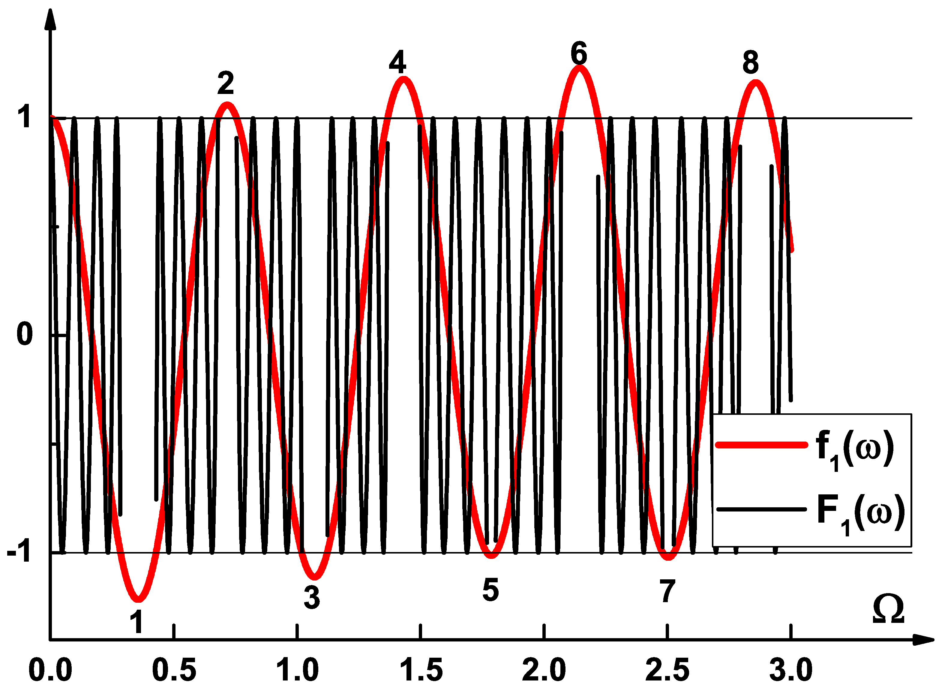
As shown in Ref. [
8], this model structure exhibits a topological interface state localized in the spectral region 7 in
Figure 2, where we have displayed the functions
and
in Equation (
3), calculated from Equations (7)–(12). Notice that, ignoring some quantitative details, the curve
is essentially the same as that for
. This means that since the frequency ranges for which
, with
, correspond to spectral regions of stop bands, the bandgaps of one of the infinite crystals overlap with those of another one, but only one of the overlapping regions support a localized mode. This can be verified by calculating the Zak phases associated with the band structure of the infinite version of
and
and noting that in region 7 the topological phase transition occurs, guaranteeing the existence of the interface mode. One can use two approaches to calculate the Zak phase
of each isolated band
n. In one of them,
is expressed as an integral over the Brillouin zone in the reciprocal space of the Berry connection, whereas in the second one we can use the symmetry of the band edge states. In the latter, if the two band edge states of band
n have the same symmetry,
, otherwise
. Using the symmetry approach and the fact that the zeros of the
-dependent functions in Equations (8)–(11) determine the symmetry properties of modes [
24], it was found that
and
for the infinite
superlattice, while
and
for another one, where
and
are, respectively, the Zak phases of the bands located below and above the gap in region 7 in
Figure 2. Note the topological phase transition.
Further, since the interface modes are formed in the combined structure
, it is important to know how the bandgaps of the infinite crystals associated with
and
are reflected in the corresponding finite ones. To see this, we first use Equation (
2) to obtain the expression
for the dispersion relation of
with
, where
and
are the Bloch wavevector and width of photonic crystal
, and
was introduced in Equation (
3). It follows immediately from Equation (
18) that the spectral regions where
is a complex (real) quantity are quantitatively reproduced by
. That is, the spectral regions where the infinite version of
exhibits bandgaps (pass bands) are exactly the same as those for
. This general result is illustrated in
Figure 3 for the model structure considered above.
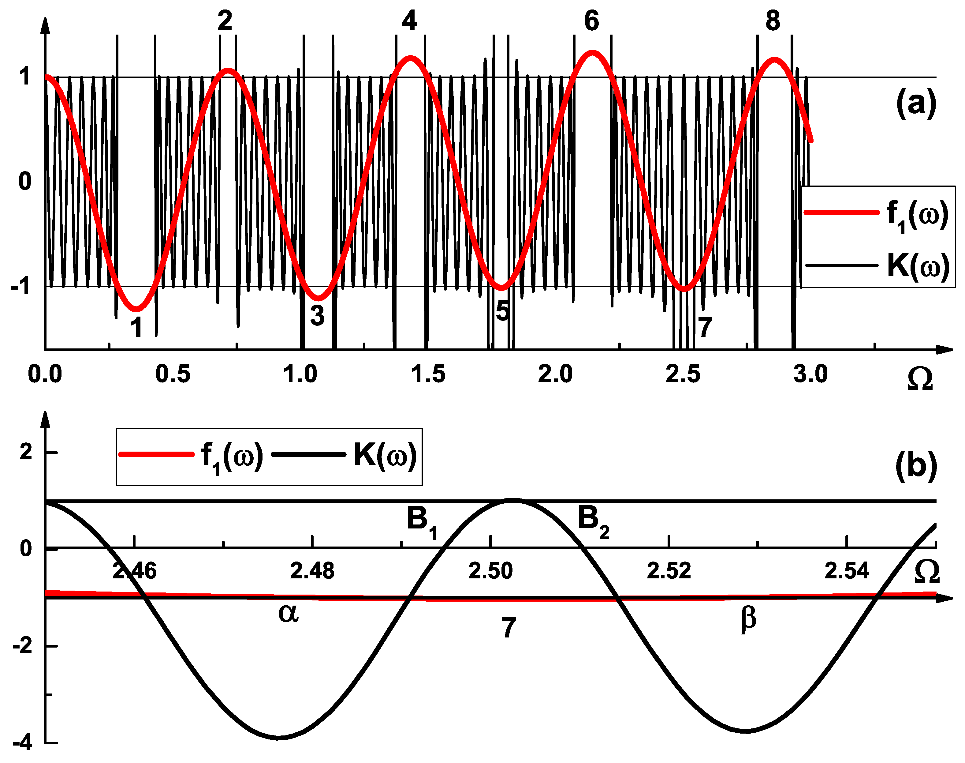
Furthermore, to compare the spectral distribution of bandgaps in the infinite crystals with that of the combined structure
, the functions
in Equation (
3) and
in Equation (
5) are depicted in
Figure 4a as functions of
. As one can see, both distributions are essentially the same, except in region 7 where
S exhibits the topological interface state. This suggests a certain correlation between the band structure of
S and the characteristics of these states, which will be investigated next. Of course, the analysis will be carried out in a certain frequency interval
including the frequency range where the mode is localized.
We begin by presenting in
Figure 4b the results shown in
Figure 4a, but for
varying within the chosen interval
. Note that in such an interval the band structure of
S exhibits two bands
and
sandwiched between two similar bandgaps labeled
and
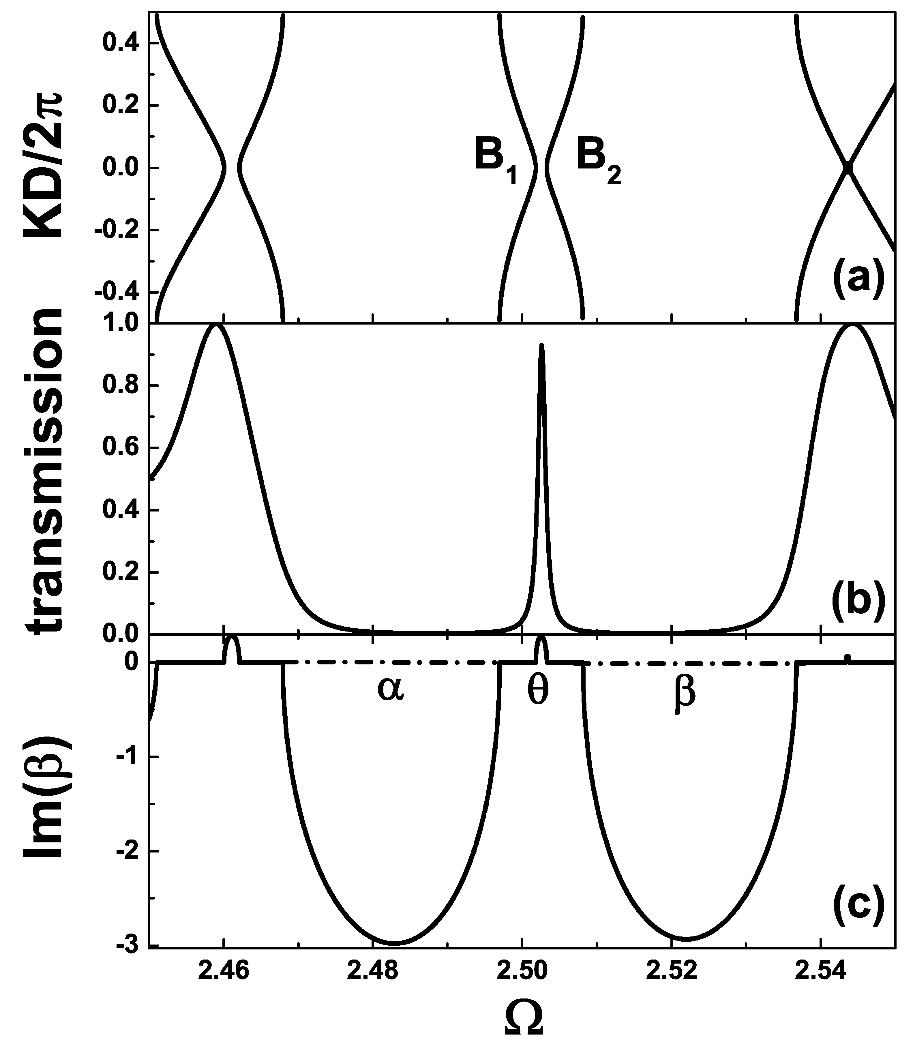
. In order to understand the origin and properties of these bands, we have displayed in
Figure 5,
Figure 6,
Figure 7 and
Figure 8 the dependence with
(in units of
) of bands
and
, the imaginary part of the Bloch phase
, and the transmission spectrum
, calculated from Equation (
16) for increasing values of the number
N of unit cells. As one clearly sees in each one of these figures, (
i) the bands
and
are separated by a minigap of width
determining a frequency range where
reaches its peak value and
. While these results can be understood as being due to topological effects, the inequality is a consequence of the fact that
. (
ii) The bands
and
are located in a frequency interval
determined by the nearest edges of the similar
and
bandgaps and are distributed in such a way that one is the mirror image of the other. This explains the
location and properties of the transmission peak structure
. In fact, when
increases from left to right,
increases with
within the
passband and decreases inside the
passband, forming the symmetric transmission peak structure observed in these figures.
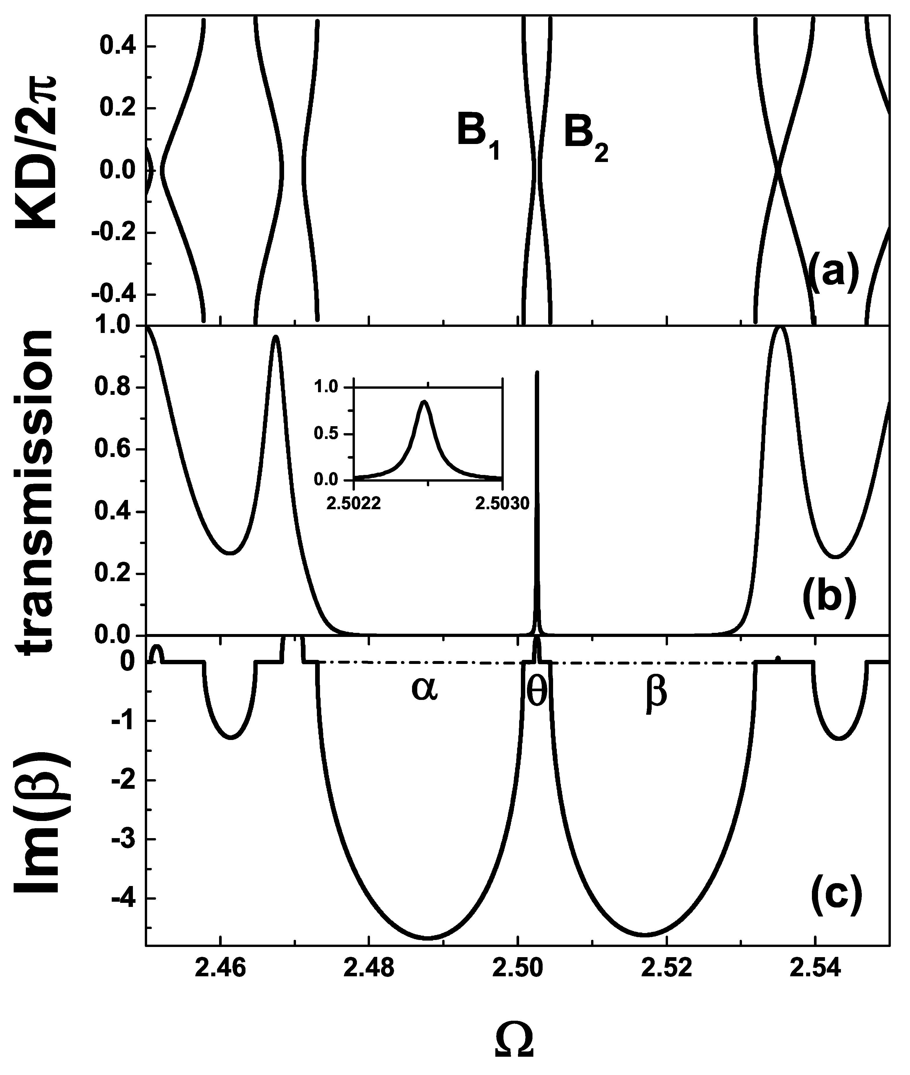
It is clear from
Figure 5,
Figure 6,
Figure 7 and
Figure 8 that the interval
is a decreasing function of the number
N of unit cells, leading to a reduction in the minigap width
and, therefore, to a decrease in the transmission peak width. It is important to notice that these modifications are accompanied by a decrease in the resonant transmission peak, which tends to disappear for sufficiently large values of the number
N of unit cells. Physically, this behavior is a direct consequence of the fact that, for
, the
and
bandgaps come together, leading to the formation of a relatively large bandgap, which modifies the propagation of an electromagnetic wave through the combined structure substantially. Certainly, if the frequency of the incident wave is inside such a bandgap, it cannot propagate through the structure and will be completely reflected. Mathematically, since the resonant transmission peak is formed in the frequency range where the bandgaps of the infinite crystals associated with
and
overlap, the Bloch phases
and
in Equation (
6) are complex quantities, which can be written as
and
at the Brillouin zone center and edge, respectively, where
is a real angle. Using these expression for
and
in Equations (6) and (14)–(16), it is straightforward to show that the transmission spectrum
decreases exponentially with the number
N of unit cells for
.
We have added two insets in panel (b) of
Figure 7 and
Figure 8, where we present a zoom-in of the central peak close to
. The zoom-in has been performed to the point of determining that there is no longer a way to hide the height of the transmission peak. Note that as the value of
N increases, the width of the central peak near
becomes smaller, and its height decreases, as expected.
It should be added, finally, that while the topological phase transition occurring between
and
guarantees the existence of the topological interface modes [
8], the configuration of bands and bandgaps discussed above determines the physical mechanism supporting them and the properties of the corresponding resonant transmission peaks, whose characteristics can be controlled by the number
N of unit cells. Such a control can be used to design structures with the desired features.


