Article

Electron Diagnostics for Extreme High Brightness Nano-Blade Field Emission Cathodes

1
Department of Physics & Astronomy, UCLA, Los Angeles, CA 90028, USA
2
Department of Physics, Friedrich-Alexander-Universit at Erlangen-Nurnberg (FAU), 91054 Erlangen, Germany
*
Authors to whom correspondence should be addressed.
Current address: 475 Portola Plaza, Los Angeles, CA 90095, USA.
Instruments 2019, 3(4), 57; https://doi.org/10.3390/instruments3040057
Submission received: 9 September 2019 / Revised: 9 October 2019 / Accepted: 10 October 2019 / Published: 16 October 2019
(This article belongs to the Special Issue Physics and Applications of High Brightness Beams)

Abstract

:
Electron beams are essential tools in modern science. They are ubiquitous in fields ranging from microscopy to the creation of coherent ultra-fast X-rays to lithography. To keep pace with demand, electron beam brightness must be continually increased. One of the main strategic aims of the Center for Bright Beams (CBB), a National Science Foundation Science and Technology Center, is to increase brightness from photocathodes by two orders of magnitude. Improving the state-of-the-art for photoemission-based cathodes is one possibility. Several factors have led to an alternative design becoming an increasing necessity; the nanoscale structure. Field emission sources from nano-tips would be an ideal candidate were it not for their low current and damage threshold. A 1-dimensional extended nano-fabricated blade, i.e., a projected tip, can solve the problems inherent in both designs. The novel geometry has been demonstrated to produce extremely high brightness electron beam bunches and is significantly more robust and easier to manufacture than traditional photocathodes. Theory indicates electron emission up to keV energies. We thus present a system of diagnostics capable of analyzing the cathodes and assessing their viability. The diagnostics are designed to measure the electron spectrum up to keV energies, with sub meV resolution at <100 eV, mean transverse energy (MTE), emission uniformity, and cathode lifetime. We also report preliminary data on total extracted charge and maximum detectable electron energy with a simplified retarding field spectrometer.

1. Introduction

Electron beams and electron accelerator technologies are critical for many modern technologies and scientific disciplines. They are ubiquitous in fields that utilize ultra-fast electron diffraction, microscopy, lithography, and free-electron-lasers for example [1,2,3]. The question then becomes one of obtaining electron bunches suitable for use in these applications. The answer is the photocathode, a general class of objects known to emit electrons when exposed to light. Beam brightness is one of the most important figures of merit for any electron beam. Various methods have been developed to improve and maintain this brightness as the electron beam is accelerated. Continuing the development of electron beam brightness then becomes of critical importance. The Center for Bright Beams, a National Science Foundation Science and Technology Center was founded to meet this end. A factor of 100 increase in the brightness from photocathodes is one of its main strategic aims.
The state of the art in electron photocathodes is primarily in the realm of materials that emit electrons based on the photoelectric effect. They take advantage of low work function from precision-engineered band gaps to provide electron bunches of certain energies when illuminated with the corresponding wavelength of laser light. In normal working operation, they are capable of generating milliamp currents at thermal emittances far below single mm-mrad/mm(rms). As a benchmark, we note that alkali-antimonide cathodes, for example, are capable or producing emittances below 0.05 mm-mrad/mm(rms) for a laser system comparable to our own; that is when using an infrared laser with 0.15 mm root mean square (RMS) spot size [4].
However, as the need for brighter beams becomes an increasing necessity, alternative photocathodes are under increasing investigation. Many intrinsic properties make them non-ideal candidates for brightness increase. They are difficult to manufacture and maintain for example. They require difficult to produce atomic smoothness and ultra-high vacuum (UHV) storage. In addition, any non-uniformity on the surface creates potential hot spots which must be experimentally determined before they are used in further experiments [5]. One possible alternative is the class of precision machined nano-structures [6]. We thus seek to identify and characterize such a structure for future use as an extremely high brightness photocathode.
There exists a class of nanostructure emitters on which we can base our cathode geometry. Tunneling electron microscopy (TEM) uses precision manufactured tip-based electron emitters. Field emission is the dominant regime for these sources rather than photoelectric emission. An incident light field is used to lower the potential barrier at the surface of an emitting material such that electrons can tunnel out of the surface. The field is in a mature stage of development and thus offers a large body of knowledge and experience which can inform our experiments [7]. Tips could be examined as potential photocathodes were it not for their low emission current and damage threshold. An extended surface would alleviate many of the problems intrinsic in existing cathode sources; increasing the emission area by many orders of magnitude and increasing the damage threshold significantly, allowing for much higher light fields to illuminate the cathode. We have thus endeavored to manufacture and test a nanoblade, in other words a projected tip geometry.
Ease of manufacture is critical to the advantage of these cathode structures. The process involves an anisotropic chemical wet-etching of a silicon wafer composed of planes of Si{111} on Si{110} [8]. The first step involves coating a silicon wafer with a material known as photoresist. A mask is machined which serves as a template for where the photoresist should be removed. Laser illumination removes the photoresist everywhere not covered by the mask. These locations are where the anisotropic etching will take place. The wet-etch acid bath is then used to cut away at the now exposed areas of silicon. The anistropy refers to the etch itself which for the given silicon layering leads to a trapezoidal cross section rather than a circular cross-section as would be the case for an isotropic etch [6]. A chemical bath is used to remove the remaining photoresist. The process is then repeated for a second time, etching the single blade into the double blade. The end result of the process leaves behind two triangular cross sectioned ridges, 250 μm tall with atomically sharp edges. On top of this, an additional metallic material can be sputtered. For the case of tungsten, 35 nm of tungsten are sputtered onto the silicon. For the case of gold, an additional 5 nm thick layer of chromium is required to act as an adhesive between the silivon substrate and the gold layer. Scanning electron microscope (SEM) images of the gold-sputtered samples are depicted in Figure 1.

2. Materials and Methods

The first step in determining useful diagnostic techniques to understand the cathode performance is to identify a number of figures of merit and compare it with the state of the art. In-depth development of the theory involved in this sort of high field emission is ongoing. As a result, we must use a simplified approach to obtain expectations for the scaling of total current that we expect. To this end we can consider a Fowler–Nordheim tunneling approach [9,10]. The approach is highly simplified but sufficient now for a comparison with preliminary diagnostics. The regime is that of cold field electron emission.
J = e 3 2 π h ( μ / ϕ ) 1 / 2 μ + ϕ E 2 exp [ 4 π 8 3 m e h ϕ 3 / 2 E ]
where J is the current per area in units of A/cm2, h is Planck’s constant, m is the mass of the electron, ϕ is the work function, μ the Fermi energy of the illuminated material, e is the elementary electron charge, and E is the peak electric field parallel to the surface vector of the material.
The materials that we use for the deposition on the tungsten blades, as previously mentioned, are tungsten and gold. The peak fields can be obtained from the laser parameters. Given peak intensities between 1012 and 1013 W/cm2, we have peaks fields between 1–3 GV/m. Now to account for the blade rather than planar geometry we consider a calculation of electric field enhancements that one would obtain from the boundary conditions of the blade geometry. Using finite difference time domain (FDTD) simulations, we compute a factor of five increase of peak fields for an 800 nm pulse. We thus expect peak fields in the range 5–15 GV/m.
The simulation involves using a plane wave source with Gaussian time profile incident on the blade from above at an angle of incidence of 5°. A Fourier transform is then used to obtain the frequency domain field enhancement of the x-coordinate of the field. This component is parallel to the surface vector of the blades and so in this approximation would be the field responsible for electron emission. The particular geometry we use in this case is an opening angle of 54° and a thickness of 15 nm corresponding to a radius of curvature of the nanotip of an equivalent value. The results at 800 nm incident laser field for the E x field enhancement are plotted in Figure 2.
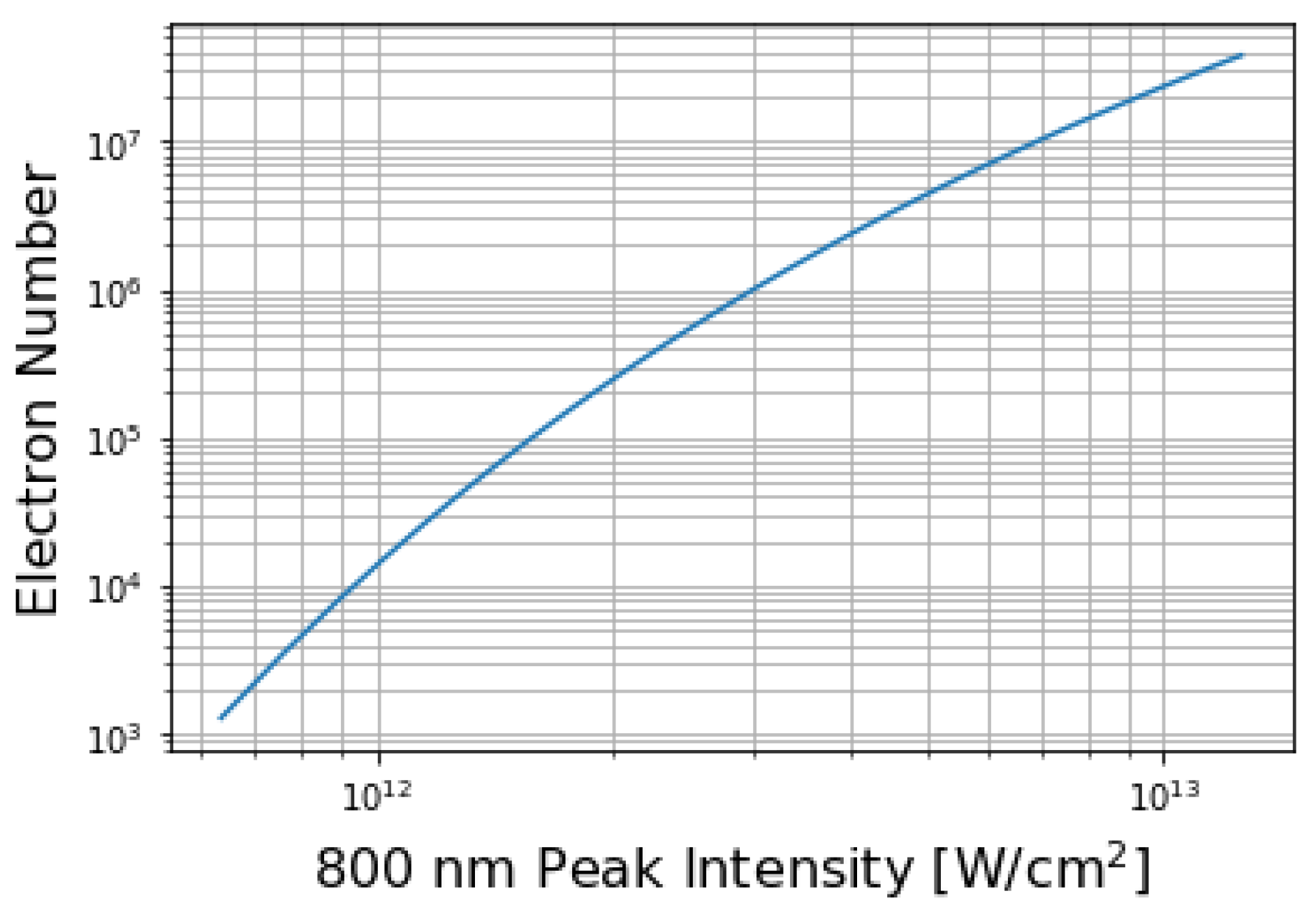
Now using the picomotor controls we can adjust the blade sample position and angle such that we have full illumination of the 15 mm length of the blade within the 100 micron radius spot size. Then considering an effective emission circumference on the tip of about 1 nm and and noting the 35 femtosecond pulse length, we can obtain the results plotted in Figure 3.
We also consider the effect of RMS averaging over a period and slight modification in geometry to our Fowler–Nordheim estimate but determine their impact to be small [10,11]. Of critical importance though is to precisely characterize the electron spectrum, mean transverse energy (MTE), intrinsic emittance, life time, and uniformity [12]. The mean transverse energy (MTE) refers to a self explanatory quantity that can be determined as
E = p 2 2 m
where p 2 is the average squares transverse momentum of the electrons and m e is again the electron mass. So we can see that a measurement of the mean transverse energy requires only a measurement of the electron beam divergence. In doing so we should also be able to obtain a measurement of the RMS intrinsic cathode emittance. The remaining two diagnostics, lifetime and uniformity, are also straight forward and should generally involve an exhaustive examination of multiple manufactured blades tested over a long period of time.
We then further note that from theory we should expect to observe electron flux peaks at harmonics of the incident photon energy [13]. We have a Ti:Sapphire laser at 800 nm which implies a photon energy of 1.53 eV. We thus expect peaks at 1.53 eV intervals. The theory also predicts electrons emitted up to keV energies. We then have three general properties from which we can characterize the energy spectrum in an improved manner.
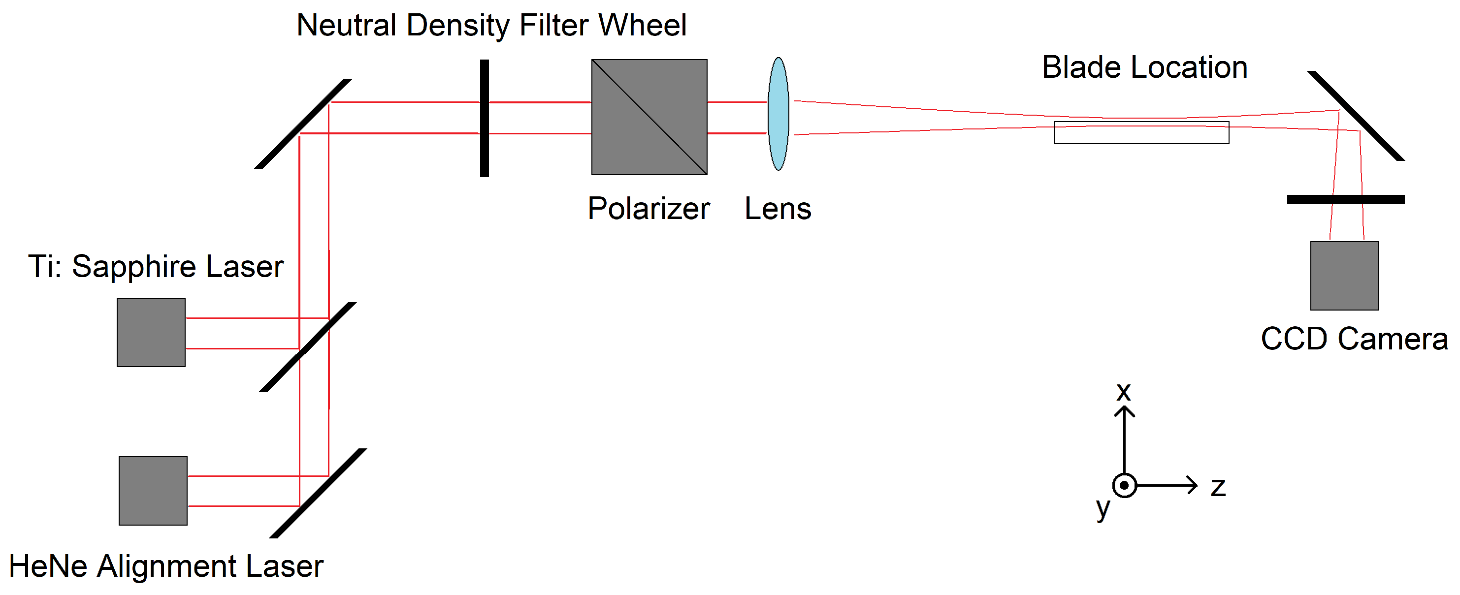
Our diagnostics must also be easily integrated into the general optical path geometry, a simplified version of which is depicted in Figure 4. After aligning the laser path to be at first co-linear with the longitudinal direction of the blade samples, a neutral density filter wheel is used to selectively attenuate the beam to a dynamic range between 20 μJ to 600 μJ. The attenuated beam is then polarized parallel to the blade surface vector and focused with a Raleigh range of 20 mm so as to fully contain the full 15 mm length of the blade sample. Fine adjustment of the sample is then performed with three stepper motors giving three translation degrees of freedom, and three picomotors allow three rotational degrees of freedom. We can also adjust the incident polarization to measure its effect on the emission currents. Eight samples at a time are mounted on a machined piece of aluminum with through holes of varying diameters to allow orientation of the sample holder using the projection of the a helium-neon alignment laser on the CCD camera.

2.1. Detectors

A physical electron detector is the most important component of the diagnostics. Both a Faraday cup and multichannel plate (MCP) coupled to a phosphor screen were examined. The former gives more precise measurements of total charge and the latter amplifies small electron signals. The design used for the MCP is a doubled layered chevron design with a 107 gain [14]. They are also able to be spatially resolved on the phosphor screen to be imaged with a CCD camera and also rough measurements of charge.

2.2. Einzel Lens

Due to the extended nature of the source and the long drift space between sample and detector (on the order of tens of centimeters) a focusing optic is needed to transport electrons from one to another. The ideal solution here is an electrostatic element called an einzel lens. The important property is the preservation of energy of focused electrons. One of the simplest einzel lens geometries is an array of three cylindrical electrodes co-linear with the longitudinal axis of the beam focus. In general, the focal length of such an einzel lens cannot be determined analytically, or at least not simply, and thus we must numerically compute an effective focal length using a parameter sweep of the incident beam energy and lens voltages [15]. The lens in certain regimes should have a roughly linear function relating focal length to electron energy. We then have, for the general geometry that is implied above, that the focal length needs to be between 15 to 20 cm. The case of a simple, three cylinder einzel lens is depicted in Figure 5. The general figure of merit in the design is also transmission efficiency, which can be negatively affected by different ion optical aberrations [15].
As a general comparison, we also note that a magnetic focusing element would not be appropriate in our case for a number of reasons. The sensitivity needed by the spectrometer and einzel lens diagnostics would be negatively impacted by any current instability in the magnetic coils and permanent magnets have no tunability. Electrostatic focusing elements are also significantly more compact and easier to integrate with the rest of the diagnostic.

Filtering Apparatus

Two different energy filters were examined. A series of electrostatic mesh filters can be added to the end of the lens in order to provide a source of simple energy selection with a field smoothed by multiple filters. This retarding field spectrometer could thus be used to replicate previous results with collaborators in Erlangen who used similar designs [16]. A 3D rendering of the design is depicted in Figure 6.
A pinhole mask of a small diameter was also examined to be affixed to the end of the lens components. The lens with pinhole rather then retarding grids will henceforth be referred to as an electron beamlet extractor. Tuning the focal length such that only certain energies make it through would then create energy-selected electron beamlets whose divergence is thus MTE.

2.3. Hemispherical Deflection Analyzer

Both filtering apparatus are unable to measure with the degree of certainty the longitudinal energy and thus the full energy spectrum, since co-linear electrons appear identical. The best method to make this measurement is through the design of a robust electron spectrometer. General electron spectrometers can be classified into two types: deflection analyzers and mirror analyzers, both of which are diverse groups with many possible geometries [15]. We opt for a deflection analyzer, an electrostatic device that couples the position and energy of a charged particle, since we can resolve this on the phosphor screen with great precision. Due to considerations relating to the general optics setup and the desire for a highly modular spectrometer, the 180 degree hemispherical deflection analyzer was chosen since this can be simply integrated with existing conflat vacuum flange hardware. Mirror-type analyzers are more difficult to implement in our particular experimental geometry due to the presence of the MCP and/or Faraday cup as the primary detector. Deflection analyzers are easier to machine and work better with the CF flange geometries with which we are working.
It is known that the most useful figures of merit for an electron spectrometer are transmission efficiency and energy resolution [15]. We then define this resolution as E = Δ E E 0 where Δ E is the full width at half max of a function which we shall call the transmission function. At the same time, E 0 is the design energy for which the device is tuned at any given time. We can consider this geometry to be analogous to angularly resolved photoemission spectroscopy (ARPES). We can obtain the design energy in terms of the radii by noting the voltage between the two hemispheres should be of the following form
V = c 1 r + c 2
where the constants are given by the following
c 1 = V 0 r 1 r 2 r 1 c 2 = V 0 r 1 r 2 r 2 r 1
and V 0 is the inner sphere potential and r 1 the inner radius and r 2 is the outer radius. We then refer to a design radius for the particle energies that we want as the average radius
r d = r 1 + r 2 2 .
Which itself then implies the design energy is the following
E d = c 2 e 2 r d
from which we can obtain the design energy in terms of the radii
E d = V 0 r 1 r 2 r 2 2 r 1 2 .
The constant of proportionality between V 0 and E d we then call the calibration factor. Now that we have the design energy for an ideal hemispherical deflection analyzer (HDA) we need several other parameters for comparison of the real geometry with the idealized fields. Magnification, denoted M refers to the ratio between the transverse cross-section at the exit and entrance of the HDA. Finally, we consider the opening angular acceptance of the device, denoted D, which gives a limiting factor in terms of the transverse energy allowed into the HDA [15].
Additional consideration was made to limit the effects of non-ideal fringing fields in the HDA. We note the difference between trajectories for an ideal field and the real apertures with fringing fields. We thus examine five techniques to help reduce the problem. The first two involve adding biasing additions at the entrance and exit apertures to smooth the fields. The Herzog corrector is a biased plate and the Jost corrector is a set of biased electrode grids [17,18]. The next two techniques are positive and negative bias paracentric entries. In these schemes, the electron beamlets entering the HDA are injected at a radius less than or greater than the design radius, respectively [19]. The final technique involves reducing the opening angle of the inner hemisphere such that it is is less than 180° and the flat face is slightly conical.

2.4. Simulation

In addition to the focal length of the einzel lens geometry, the HDA figures of merit needed to be computed through numerical simulation for a number of different parameters. Simulation of all particle dynamics in order to obtain necessary parameters and comparison were done with IBSimu, a C++ library optimized for ion beam simulation [20]. Simulated beam dynamics using Gaussian energy distribution were simulated through spectrometer and compared with the ideal response using monochromatic beams. In select cases, the simulations were validated with GPT [21].

3. Results

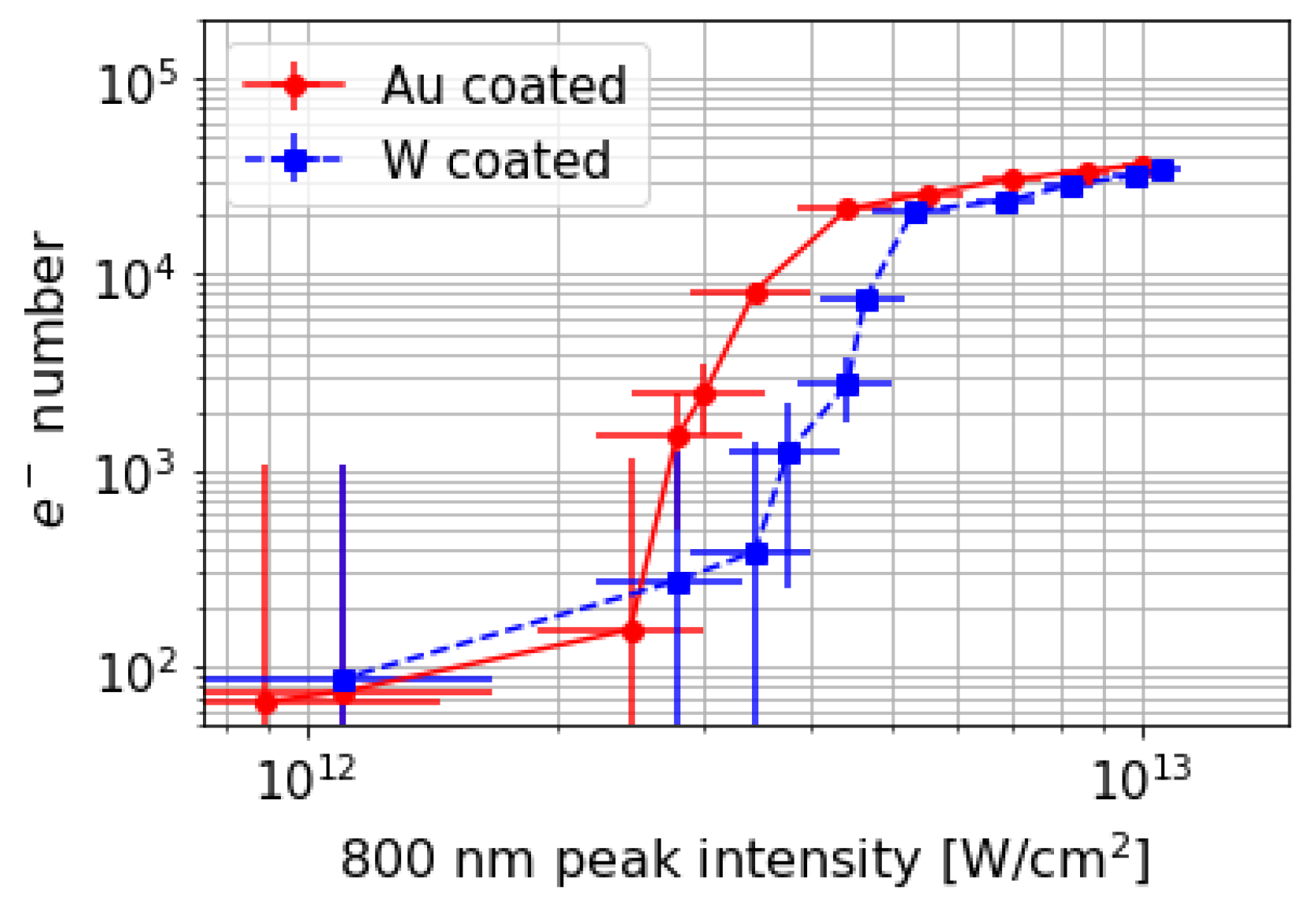
Initial measurements with electrostatic lens focusing verified electron emission curves as a function of incident laser intensity. Integrated signals from voltage fluctuations on the MCP array were used to determine the charge per 35 fs laser pulse at for a range of laser intensities. The data for tungsten and gold coated blades are plotted in Figure 7. In addition, the simplified retarding field spectrometer verified the emission of electrons up to keV energies. The emission as a function of polarization of incident laser intensity was also measured and the data plotted in Figure 8. The measurements were made at 6 × 10¹² W/cm2.
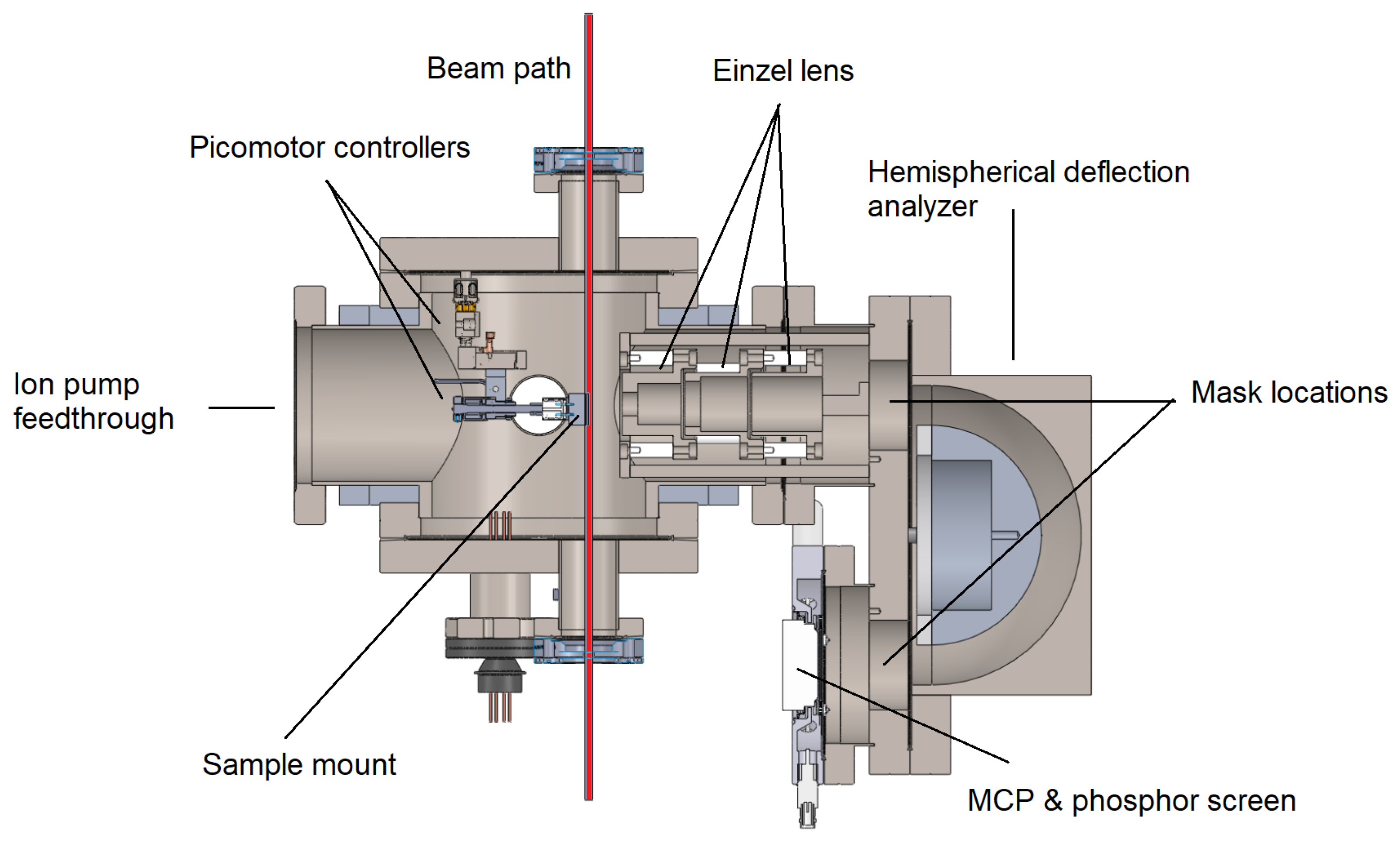
Results from the examination of spacial distribution on the phosphor screen were anomalous. Multiple lines of focus were observed, rather than the expected circular focal spots, most likely due to a combination of the extended nature of the blade and significant spherical aberration due to the large angular acceptance of the lens. Due to the deficiencies with the retarding field spectrometer, a beamlet extraction device and energy spectrum diagnostics were designed. The full spectrometer setup is depicted in Figure 9. The HDA figures of merit for the designed system are computed through simulation with a rectangular beam source 100 μm × 15 mm and Gaussian longitudinal energy. The results are listed in Table 1. The energy distribution for the spectrometer with pinhole mask was determined to be on the order of 1% of the design energy. This figure was determined by simulating a line charge initial condition with Gaussian energy distribution. The energy resolution then falls in the 0–100 eV range necessary to resolve the 1.53 eV separated peaks in the expected distribution.
The beamlet extractor component of the spectrometer yielded emission currents too small to detect so removal of the pinhole was necessary. The process of commissioning the lens structure on its own is ongoing. Anomalous magnetization was found in the chamber itself, so extensive degaussing was performed. The same four samples of gold and four samples of tungsten coated blades have been in use for over 10 h of cumulative operation with a detectable reduction in electron emission current.

4. Discussion

Future directions are to finish spectrometer commissioning and then take measurements of the relative lifespan of the sample and uniformity. Discussions are also underway concerning experiments with annealing and cutting away the sides of the sample to illuminate the sides of the blade.
In addition, consideration was put into examining different techniques to mitigate the effects of spherical aberration in the lens geometry. Several einzel lens geometries were simulated in IBSimu to compare their ability to focus the electron beam and to preserve the energy. Inspired by the designs proposed by Riddle et al. [22], we analyzed three different geometries: the standard symmetrical lens with three electrodes of equal length; the asymmetrical lens with a longer middle electrode which is shifted towards the last electrode; and another asymmetrical lens with a longer middle electrode which is also shifted and linearly tapered. The two additional geometries along with examples trajectories are plotted in Figure 10 and Figure 11.
The results of these simulations are plotted in Figure 12 and Figure 13 in the form of gaussian fits to binned results over many trials. An einzel lens with a longer middle electrode that is shifted towards the last electrode could outperform its symmetric counterpart without altering the energy of the electron beam. The tapered version may cause some technical difficulties, so the advantage is not significant.

5. Conclusions

Manufacture and commissioning of the full electron spectrometer are still ongoing. The einzel lens will be modified to incorporate the asymmetric design. Preliminary diagnostics tests were run with detectors, einzel lens focusing, and both filtering techniques. These results have verified the presence of electrons up to keV energues with bunches in excess 10 4 e at 20 GV/m incident laser fields for both gold coated and tungsten coated blade cathodes. It is also necessary to note that one silicon wafer has space for over 60 individual, 5 mm × 15 mm diced samples so rapid production is a distinct possibility. Potential future directions include different material coatings and increasing the number of blades on a cathode sample to scale up the charge of the electron emission. Coated nanoblades thus present a promising new cathode design for high brightness electron beams which can be usefully characterized with the proposed diagnostics.

Author Contributions

Research contributions are as follows: conceptualization, G.L., T.P., B.N., and J.R.; data curation, G.L. and K.S.; formal analysis, G.L.; funding acquisition, J.R.; investigation, G.L., K.S., V.Y., R.R., O.W., and Y.S.; methodology, G.L., K.S., Y.Z., T.P., O.W., Y.S., and B.N.; project administration, G.L. and J.R.; resources, B.N. and J.R.; software, G.L. and Y.Z.; supervision, J.R.; validation, G.L. and V.Y.; writing—original draft, G.L., K.S., and Y.Z.; writing—review & editing, G.L. and J.R.

Funding

This work was supported by the U.S. National Science Foundation under Award PHY-1549132, the Center for Bright Beams.

Acknowledgments

The authors would like to acknowledge the valuable contributions of Noah Bodzin for the excellent transverse SEM of the blades.

Conflicts of Interest

The authors declare no conflict of interest. The funders had no role in the design of the study; in the collection, analyses, or interpretation of data; in the writing of the manuscript, or in the decision to publish the results.

References

  1. Polman, A.; Kociak, M.; Javier García de Abajo, F. Electron-beam spectroscopy for nanophotonics. Nat. Mater. 2019. [Google Scholar] [CrossRef] [PubMed]
  2. McCord, M.A.; Rooks, M.J. SPIE Handbook of Microlithography, Micromachining and Microfabrication; SPIE: Bellingham, WA, USA, 2000. [Google Scholar]
  3. Couprie, M.E. New generation of light sources: Present and future. J. Electron Spectrosc. Relat. Phenom. 2014, 196, 3–13. [Google Scholar] [CrossRef] [Green Version]
  4. Cultrera, L.; Gulliford, C.; Bartnik, A.; Lee, H.; Bazarov, I. Ultra low emittance electron beams from multi-alkali antimonide photocathode operated with infrared light. Appl. Phys. Lett. 2016, 108, 134105. [Google Scholar] [CrossRef] [Green Version]
  5. Matsuba, S.; Honda, Y.; Jin, X.; Miyajima, T.; Yamamoto, M.; Uchiyama, T.; Kuwahara, M.; Takeda, Y. Mean Transverse Energy Measurement of Negative Electron Affinity GaAs-Based Photocathode. Jpn. J. Appl. Phys. 2012, 51, 046402. [Google Scholar] [CrossRef]
  6. Rao, A.V.N.; Swarnalatha, V.; Pal, P. Etching characteristics of Si110 in 20 wt% KOH with addition of hydroxylamine for the fabrication of bulk micromachined MEMS. Micro Nano Syst. Lett. 2017, 5, 23. [Google Scholar] [CrossRef]
  7. Ciappina, M.F.; Pérez-Hernández, J.A.; Shaaran, T.; Lewenstein, M.; Krüger, M.; Hommelhoff, P. High-order-harmonic generation driven by metal nanotip photoemission: Theory and simulations. Phys. Rev. A 2014, 89, 013409. [Google Scholar] [CrossRef] [Green Version]
  8. Pal, P.; Singh, S. A New Model for the Etching Characteristics of Corners Formed by Si111 Planes on Si110 Wafer Surface. Engineering 2013, 5, 1–8. [Google Scholar] [CrossRef]
  9. Wu, A.C.; Mes, K.H.; Tigner, M.; Zimmermann, F. Contemporary Physics. In Handbook of Accelerator Physics and Engineering, 2nd ed.; World Scientific Publishing: Singapore, 1980; pp. 394–395. [Google Scholar]
  10. Lucier, A.S. Preparation and Characterization of Tungsten Tips Suitable for Molecular Electronics Studies. Master’s Thesis, McGill University, Montreal, QC, USA, 2004. [Google Scholar]
  11. Wang, J.W. RF Properties of Periodic Accelerating Structures for Linear Colliders. Ph.D. Thesis, Stanford University, Stanford, CA, USA, 1989. [Google Scholar]
  12. Herr, W. CERN-2014-009. In Proceedings of the CAS-CERN Accelerator School: Advanced Accelerator Physics, Trondheim, Norway, 19–29 August 2013. [Google Scholar]
  13. Wachter, G. Simulation of Condensed Matter Dynamics in Strong Femtosecond Laser Pulses. Ph.D. Thesis, Technical University of Vienna, Wien, Austria, 2012. [Google Scholar]
  14. Wiza, J.L. Microchannel Plate Detectors. Nuclear Instrum. Methods 1979, 162, 587–601. [Google Scholar] [CrossRef]
  15. Roy, D.; Tremblay, D. Design of electron spectrometers. Rep. Prog. Phys. 1990, 53, 1621. [Google Scholar] [CrossRef]
  16. Paschen, T.; Roussel, R.; Heide, C.; Dienstbier, P.; Mann, J.; Seiffert, L.; Fennel, T.; Rosenzweig, J.; Hommelhoff, P. Strong-field photoemission from a nanometric blade structure. Phys. Rev. X 2019. under review. [Google Scholar]
  17. Nishigaki, S.; Kanai, S. Optimization of the Herzog correction in the hemispherical deflector analyzer. Rev. Sci. Instrum. 1968, 57, 225. [Google Scholar] [CrossRef]
  18. Jost, K. Fringing field correction for 127 degrees and 180 degrees electron spectrometers. J. Phys. E Sci. Instrum. 1979, 12, 1001. [Google Scholar] [CrossRef]
  19. Sise, O.; Zouros, T.J.M.; Ulu, M.; Dogan, M. Novel and traditional fringing field correction schemes for the hemispherical analyser: comparison of first-order focusing and energy resolution. Meas. Sci. Technol. 2007, 18, 1853. [Google Scholar] [CrossRef]
  20. Kalvas, T.; Tarvainen, O.; Ropponen, T.; Steczkiewicz, O.; Arje, J.; Clark, H. IBSIMU: A three-dimensional simulation software for charged particle optics. Rev. Sci. Instrum. 2010, 81, 02B703. [Google Scholar] [CrossRef] [PubMed]
  21. Der Geer, B.; De Loos, M. The general particle tracer code: Design, implementation and application. J. Bus Commun. 2001. [Google Scholar] [CrossRef]
  22. Riddle, G.H.N. Electrostatic einzel lenses with reduced spherical aberration for use in field emission guns. J. Vacuum Sci. Technol. 1978, 15, 857. [Google Scholar] [CrossRef]
Figure 1. Scanning electron microscope (SEM) images of double-blade gold-coated silicon samples. (a) Photo at 100 micron scale and 45 degrees relative to the longitudinal direction. (b) Photo of transverse cross section at 100 nm scale. Note the lighter contrast corresponds to ≈15 nm thick gold coating.
Instruments 03 00057 g001
Figure 2. E x component of field enhancement for 800 nm pulse on gold coated blade using finite difference time domain (FDTD) simulations.
Instruments 03 00057 g002
Figure 3. Plot of numbers of electrons emitted as a function of laser intensity in simplified model using Equation (1).
Instruments 03 00057 g003
Figure 4. General optics table geometry involved in nano-blade illumination experiments before adding electron diagnostics.
Instruments 03 00057 g004
Figure 5. Focusing in a generic three-cylinder einzel lens. Blue solid objects are cross sections of the three cylindrical electrodes; red tracks are full trajectories of every 100th electron in the simulation; green contours represent equipotentials which are solved numerically.
Instruments 03 00057 g005
Figure 6. 3D rendering of initial retarding field spectrometer.
Instruments 03 00057 g006
Figure 7. Electron emission from tungsten coated blades from multiple trials as measured by retarding field spectrometer for both tungsten and gold coated blades.
Instruments 03 00057 g007
Figure 8. Electron emission as a function of polarization of incident light relative to the surface normal vector of the blade surface. Measurements performed at 6 × 10¹² W/cm2.
Instruments 03 00057 g008
Figure 9. Schematic drawing of the electron spectrometer, including its three main components: einzel lens, HDA, and multichannel plate (MCP) detector.
Instruments 03 00057 g009
Figure 10. The asymmetrical einzel lens.
Instruments 03 00057 g010
Figure 11. The asymmetrical einzel lens with a linearly tapered middle electrode.
Instruments 03 00057 g011
Figure 12. Focusing in three different kinds of einzel lenses. It is clear that the two asymmetrical designs result in a tighter focus.
Instruments 03 00057 g012
Figure 13. Energy preservation in three different kinds of einzel lenses. It is clear on the graph that the two asymmetrical designs result in less energy loss compared with the standard design.
Instruments 03 00057 g013
Table 1. Simulated electron spectrometer figures of merit for machined geometry with real specifications compared with simplified geometry and no fringing fields which represents the upper bound on performance. Hemispherical deflection analyzer (HDA).
HDA PropertyIdealSimulated
Calibration factor≈1.59≈1.25
Magnification1≈0.80
Acceptance angle013.75
Transmission efficiency100%80.9% ± 3.7%