Design of Comb Fabricated Halbach Undulators

Department of Physics and Astronomy, University of California Los Angeles, Los Angeles, CA 90095, USA
*
Author to whom correspondence should be addressed.
Instruments 2019, 3(4), 58; https://doi.org/10.3390/instruments3040058
Submission received: 28 August 2019
/
Revised: 24 September 2019
/
Accepted: 17 October 2019
/
Published: 19 October 2019
(This article belongs to the Special Issue Physics and Applications of High Brightness Beams)
Abstract
:An approach to fabricating Halbach array undulators using “combs” machined from single magnets is introduced. This technique is especially relevant to the fabrication of short period micro-undulators with period lengths considerably less than the few-centimeter-scale typical of current undulators. Manual, magnet-by-magnet assembly of micro-undulators would require the manipulation and alignment of thousands of magnets smaller than a grain of rice: comb fabrication dramatically increases the size of the basic unit cell of assembly with no increase in undulator period by creating many periods from a single piece, in a single machining modality. Further, as these comb teeth are intrinsically indexed to each other, tolerances are dictated by a single manufacturing step rather than accumulating errors by assembling many tiny magnets relative to each other. Different Halbach geometries, including , , isosceles triangle, and hybrid, are examined both from a theoretical perspective and with 3D magnetostatic simulations.
1. Introduction
An idealized Halbach array of permanent magnets, originally described by Klaus Halbach in 1980 [1,2] for use in multipole magnets and undulators, consists of regions of permanent magnet with smoothly rotating residual fields. The benefit of this configuration is the establishment of a “strong” and “weak” side to the array, enhancing the magnetic field on the strong side and attenuating it on the weak side. This leads to more efficient use of the available magnetic flux, giving stronger fields than other magnetization configurations. Practical realizations of Halbach arrays consist of discrete magnets, each with a unique, constant magnetization vector, arranged to approximate the idealized case. Halbach arrays have been used extensively in beamline magnets including the construction of permanent magnet wigglers and undulators [3,4,5,6] and multipole magnets including dipoles [7] and quadrupoles [8]. In addition to the pure permanent magnet (PPM) arrays, hybrid arrays consisting of both hard and soft ferromagnetic materials are also used [9,10,11]. The most common practical implementation of these hybrid arrays to the realization of undulators involves magnets with alternating polarities with their magnetization vectors oriented in the longitudinal direction, interspersed with high-saturation soft ferromagnets. Such undulators are capable of achieving gap fields significantly higher than PPM undulators, for reasons that will be discussed below.
There is growing interest in the development and use of short period undulators (or micro-undulators) [11,12,13,14,15,16], facilitated by microelectromechanical systems (MEMS) and other modern, nonconventional machining techniques. Decreasing the undulator period length decreases free-electron laser (FEL) or light source length while also producing harder radiation from lower energy electrons, which may be produced by a shorter accelerator. Comb fabrication is one approach for facilitating fabrication of micro-undulators, which has been demonstrated before for simple up–down ( in the terminology in [1]) style undulators [14]. However, here we are interested in higher-order, , Halbach arrays, as they offer superior magnetic field performance. If the minimum feature size of the manufacturing process is at least 4 times smaller than the required period, either or hybrid arrays can be used. Otherwise, isosceles triangle based arrays can provide the same period length as an for a given feature size but with improved field strength [17].
2. Methods
Comb fabrication relies on the cutting of multiple “teeth” out of a single piece of material, all of which will have the same magnetization vector. Thus, this approach gives a straightforward path in both mechanical fabrication and magnetization of the machined combs. These combs are designed in such a way that they may be slotted together to form the complete Halbach array of a single undulator jaw. One additional constraint to the design of these combs is that they must be manufacturable using only through-bulk cutting, as opposed to a depth-controllable process such as milling. This is due to the limited selection of machining processes conducive both to machining rare earth magnets, which are brittle and hard, and capable of operating at such small length scales. Two nonconventional machining processes in particular are well suited to this task, laser machining and wire electrical discharge machining (EDM), and both are through-bulk processes. A total of four geometry types will be considered: up–down (), isosceles triangle, , and hybrid arrays. The idealized cross sections of each of these geometries in the two-dimensional limit, as well as example combs for each, are shown in Figure 1.
The array is the simplest case and comb fabrication has been previously demonstrated [14]. An array based on isosceles triangles, with the same volume of magnetic material per period and same minimum feature size, produces integrated fields approximately 20% higher than the case [17]. The case offers a higher field than either of these but requires four feature lengths per period, making it unsuitable for undulators with especially short periods. An expression in [3] gives the peak field strength for PPM, rectangle magnet Halbach arrays:
where is the maximum magnetic field in the gap, is the residual magnetization of the permanent magnets, is the number of magnets per period, h is the height of the magnets, g is the gap size, and is the undulator period. This suggests that, all else held equal, an array will have 0.90 times the peak field of an idealized () Halbach array, whereas an array will have 0.64 times the ideal case. This result, combined with the findings in [17], indicates that the isosceles case will have 0.76 times the field of the ideal case. The performance of the hybrid case depends on additional factors, outlined below.
Consider a magnetic circuit that is simply a “loop” of constant cross sectional area permanent magnet with an air gap. Further, assume that the B–H curve can be approximated as linear with intercepts at , the residual magnetization, and , the coercivity:
Typical values for and for high quality neodymium magnets are 1.2 T and amp/meter, respectively [18]. Assuming negligible fringing fields, there is constant magnetic flux, , in both the magnet and gap:
where A is the cross sectional area (normal to the flux), B is the magnitude of the magnetic flux density, and the subscripts m and g refer to the magnet and gap, respectively. As there is no exciting current, the net magnetomotive force, , is zero:
where H is the magnitude of the magnetic field and g and are the lengths of the flux path in the gap and magnet respectively. Using Equations (2)–(4) along with , we find the field in the gap to be
As it was assumed that the PM loop was of constant area, , so is maximized as and . This result is a reasonably good approximation for the PPM undulator cases as confirmed by simulation.
Now, consider a magnet that is coupled to a gap by an infinite permeability yoke; the yoke will perfectly confine the flux allowing . This approximates the case of the hybrid undulator where is the thickness of the longitudinally magnetized PMs and is their area normal to this. can become large without affecting the period of the undulator so consider Equation (5) in the limit :
This result suggests that the field can become arbitrarily large as . However, this approximation is only reasonable until the yoke material saturates, violating the “infinite permeability” assertion. As high-saturation materials like vanadium permendur [18] offer saturation fields over 2.3 T, compared to the of the best available permanent magnets of ~1.2 T, hybrid Halbach undulators can provide peak fields about twice as high as a PPM array.
An important caveat for these hybrid comb designs is that, to prevent leakage between the two soft ferromagnetic yoke pieces, the sections interspersed with the magnets do not cover the whole area of the magnet, . In the particular case simulated, the yoke piece is only exposed to an effective area (See Figure 1d). This suggests magnets of approximately twice the area are required to get the same performance as would be possible if ; if the non-magnetic side-connecting pieces were brazed to the yoke material before machining, this might be achievable.
3. Results
The performance of Halbach comb arrays are simulated in Radia [18] over a range of gap sizes, g, and with several cases of the hybrid geometry shown with varying magnet areas (in terms of ). The magnets are taken to be a neodymium (NdFeB alloy) with = 1.2 T. The soft ferromagnetic yoke material is simulated as a vanadium permendur alloy with a saturation of 2.3 T and peak relative permeability of 7000. In all the cases shown, the magnet height, h, is held constant relative to for all PPM cases; this means that has square magnets, whereas magnets are rectangular. This keeps the volume of magnetic material per period constant while is varied for the most meaningful comparison. Additionally, the transverse dimension of the magnet is taken to be large relative to .
To compare between the strengths of the different configurations, it is typical to characterize undulators and wigglers in terms of a unitless parameter termed the K-value, sometimes also termed the strength parameter. K is defined [19] as
where is the maximum deflection angle of the electron beam in the undulator, e is the electron charge, is the electron mass, c is the speed of light, and is the vertical field along the undulator. To compare the strengths of undulators independent of the mean absolute field, , can be used instead:
will be derived from the simulated fields.
Referring to Figure 2, the case, although the simplest to fabricate, also gives the worst performance. For typical gap sizes on the order of , arrays offer a value of only 0.42 T, whereas the isosceles case, despite having the same minimum feature size, has = 0.52 T (24% enhancement) and the array has = 0.58 T (38% enhancement). The hybrid cases, on the other hand, shine at particularly low g values where they can offer values over 80% higher than cases.
Both the isosceles and cases appear to be converging to the residual magnet field, = 1.2 T in the limit as predicted by Equation (5), suggesting that with four magnets per period, the flux in a loop is reasonably well approximated as normal to the loop cross section. The case, however, is not converging to , since with only two magnets per period, this approximation is significantly worse. Finally, looking at the hybrid cases, it appears that the approximation from Equation (6) that is reasonably well satisfied at values of and that there are negligible returns to increasing the cross sectional area of the magnet any further. Despite being in the large limit, in the limit does not appear to be the saturation field of the yoke material. This is due to significant flux leakage between the yokes and fringing fields. Further geometry optimization may reduce this effect.
In addition to considering the field strength, the deviation of the field compared to non-comb (no non-tooth connecting pieces) Halbach arrays should be examined. For the PPM geometries, determining this effect is especially straightforward since simply taking a linear superposition of all the magnet fields is a reasonably good approximation: it is stated in [20] that “[rare earth magnets behave] magnetically very nearly like a vacuum with an impressed current. This makes it straightforward to predict analytically the field that will result from almost any configuration of blocks”. As adjacent connecting pieces can be selected to have opposing polarization, far-field errors are reduced. Further, any application particularly sensitive to such error fields can employ thicker teeth to increase the separation between the connecting magnets and the beam axis. Consider a concrete example of a undulator with and , giving a peak field, , of 0.78 T. Within a square region on axis, with side length equal to , averaged over a period, the field from an array with connecting pieces has a mean absolute error (MAE) of 0.0029 T (0.37% of ), when compared to the same configuration without connecting pieces. Any integrated effects can be mitigated by alternating the polarities of the connecting pieces between adjacent combs.
As mentioned before, the connecting pieces are especially impactful for the hybrid case, reducing the effective magnet area by approximately half compared to the actual magnet area and also limiting the maximum achievable gap field due to flux leakage and fringing. Despite these challenges, the hybrid arrays can offer higher values than any PPM array.
4. Conclusions and Future Work
A technique for fabricating Halbach arrays for micro-undulators using comb elements has been discussed. This approach obviates the need for magnet-by-magnet fabrication and improves the accuracy achievable by relying on the intrinsic indexing of the comb teeth relative to each other. Example combs for a variety of Halbach configurations, including , , isosceles triangle, and hybrid, are illustrated, all of which rely only on through-bulk, nonconventional machining processes. These combs are simulated and compared over a wide range of gap sizes using the magnetostatics code Radia. Finally, the impact of the connecting pieces on the field quality has been discussed. Further work will include determining optimal wire EDM parameters for samarium cobalt machining (previous studies for neodymium magnets have been conducted [21,22]), fabrication of proof-of-principle comb Halbach arrays, and field characterization. This work may prove to be a key component of the current UCLA effort to realize an ultra-compact X-ray free-electron laser [23].
Author Contributions
Conceptualization, N.M.; methodology, N.M.; software, N.M.; validation, N.M. and J.R.; formal analysis, N.M. and J.R.; investigation, N.M.; resources, J.R.; data curation, N.M.; writing—original draft preparation, N.M.; writing—review and editing, N.M. and J.R.; visualization, N.M.; supervision, N.M. and J.R.; project administration, N.M. and J.R.; funding acquisition, J.R.
Funding
This work was supported by U.S. Dept. of Energy Contract No. DE-SC0009914 and by the US NSF Award PHY-1549132, the Center for Bright Beams.
Conflicts of Interest
The authors declare no conflicts of interest. The funders had no role in the design of the study; in the collection, analyses, or interpretation of data; in the writing of the manuscript; or in the decision to publish the results.
References
- Halbach, K. Design of Permanent Multipole Magnets with Oriented Rare Earth Cobalt Material. Nucl. Instrum. Methods 1980, 169. [Google Scholar] [CrossRef]
- Halbach, K. Physical and optical properties of rare earth cobalt magnets. Nucl. Instrum. Methods 1981, 187, 109–117. [Google Scholar] [CrossRef] [Green Version]
- Halbach, K.; Chin, J.; Hoyer, E.; Winick, H.; Cronin, R.; Yang, J.; Zambre, Y. A Permanent Magnet Undulator for SPEAR. IEEE Trans. Nucl. Sci. 1981, 28, 3136–3138. [Google Scholar] [CrossRef] [Green Version]
- Lidia, S.; Carr, R. An elliptically-polarizing undulator with phase adjustable energy and polarization. Nucl. Instrum. Methods Phys. Res. A 1994, 347, 77–82. [Google Scholar] [CrossRef] [Green Version]
- Carr, R.; Cornacchia, M.; Emma, P.; Nuhn, H.D.; Poling, B.; Ruland, R.; Johnson, E.; Rakowsky, G.; Skaritka, J.; Lidia, S.; et al. Visible-infrared self-amplified spontaneous emission amplifier free electron laser undulator. Phys. Rev. Spec. Top.-AC 2001, 4, 43–51. [Google Scholar] [CrossRef]
- Murokh, A.; Agustsson, R.; Babzien, M.; Ben-Zvi, I.; Bertolini, L.; Van Bibber, K.; Carr, R.; Cornacchia, M.; Frigola, P.; Hill, J.; et al. Results of the VISA SASE FEL experiment at 840 nm. Nucl. Instrum. Methods Phys. Res. A 2003, 507, 417–421. [Google Scholar] [CrossRef]
- Kumada, M.; Iwashita, Y.; Aoki, M.; Sugiyama, E. The strongest permanent dipole magnet. In Proceedings of the 2003 Particle Accelerator Conference, Portland, OR, USA, 12–16 May 2003; pp. 1063–3928. [Google Scholar] [CrossRef]
- Lim, J.K.; Frigola, P.; Travish, G.; Rosenzweig, J.B.; Anderson, S.G.; Brown, W.J.; Jacob, J.S.; Robbins, C.L.; Tremaine, A.M. Adjustable, short focal length permanent-magnet quadrupole based electron beam final focus system. Phys. Rev. Spec. Top.-AC 2005, 8, 1–17. [Google Scholar] [CrossRef]
- O’Shea, F.H.; Marcus, G.; Rosenzweig, J.B.; Scheer, M.; Bahrdt, J.; Weingartner, R.; Gaupp, A.; Grüner, F. Short period, high field cryogenic undulator for extreme performance x-ray free electron lasers. Phys. Rev. Spec. Top.-AC 2010, 13, 1–12. [Google Scholar] [CrossRef]
- Elleaume, P.; Chavanne, J.; Faatz, B. Design considerations for a 1 angstrom SASE undulator. Nucl. Instrum. Methods Phys. Res. A 2000, 455, 503–523. [Google Scholar] [CrossRef]
- Eichner, T.; Grüner, F.; Becker, S.; Fuchs, M.; Habs, D.; Kunz, P.; Weingartner, R.; Backe, H.; Schramm, U.; Lauth, W. Miniature magnetic devices for laser-based, table-top free-electron lasers. Phys. Rev. Spec. Top.-AC 2007, 10, 1–9. [Google Scholar] [CrossRef]
- Ramian, G.; Elias, L.; Kimel, I. Micro-undulator FELS. Nucl. Instrum. Methods Phys. Res. A 1986, 250, 125–133. [Google Scholar] [CrossRef]
- Harrison, J.; Joshi, A.; Lake, J.; Candler, R. Surface-micromachined magnetic undulator with period length between 10 m and 1 mm for advanced light sources. Phys. Rev. Accel. Beams 2012, 070703, 1–16. [Google Scholar] [CrossRef]
- Peterson, B.A.; Oniku, O.D.; Patterson, W.C.; Le Roy, D.; Garraud, A.; Herrault, F.; Dempsey, N.M.; Arnold, D.P.; Allen, M.G. Technology development for short-period magnetic undulators. Phys. Procedia 2014, 52, 36–45. [Google Scholar] [CrossRef]
- Kinjo, R.; Shibata, M.; Kii, T.; Zen, H.; Masuda, K.; Nagasaki, K.; Ohgaki, H. Demonstration of a high-field short-period undulator using bulk high-temperature superconductor. Appl. Phys. Express 2013, 6. [Google Scholar] [CrossRef]
- Yamamoto, S. Undulator Development Towards Very Short Period Lengths. Synchrotron Radiat. News 2015, 28, 19–22. [Google Scholar] [CrossRef]
- Majernik, N.; Rosenzweig, J.B. Halbach undulators using right triangular magnets. Phys. Rev. Accel. Beams 2019, 22. [Google Scholar] [CrossRef]
- Chubar, O.; Elleaume, P.; Chavanne, J. RADIA. 1997. Available online: http://www.esrf.eu/Accelerators/Groups/InsertionDevices/Software/Radia (accessed on 16 October 2019).
- Clarke, J.A. The Science and Technology of Undulators and Wigglers; Oxford University Press: Oxford, UK, 2004. [Google Scholar]
- Brown, G.; Halbach, K.; Harris, J.; Winick, H. Wiggler and undulator magnets—A review. Nucl. Instrum. Methods Phys. Res. 1983, 208, 65–77. [Google Scholar] [CrossRef]
- Greer, J. Wire Electrical Discharge Machining of Helical Devices from Permanent Magnets. Master’s Thesis, University of Utah, Salt Lake City, UT, USA, 2011. [Google Scholar]
- Takezawa, H.; Ichimura, Y.; Suzuki, T.; Muramatsu, T.; Mohri, N. Relationship between thermal influence and magnetic characteristics in electrical discharge machining of magnetic materials. Key Eng. Mater. 2012, 516, 575–579. [Google Scholar] [CrossRef]
- Rosenzweig, J.B. Towards an Ultra-Compact X-ray Free-Electron Laser. New J. Phys. 2019. submitted. [Google Scholar]
Figure 1.
Examples of the simulated undulator configurations. The left column shows an idealized, 2D cross section omitting connecting parts. The center column shows the constituent parts of the lower jaw in a preassembly state. The right column shows the assembled state of the lower jaw array. By row: (a) array, (b) isosceles triangle array, (c) array, and (d) hybrid array. Green and yellow correspond to vertical magnetization vectors, blue and red correspond to longitudinal magnetization vectors, and gray corresponds to a high-saturation, soft ferromagnetic material.
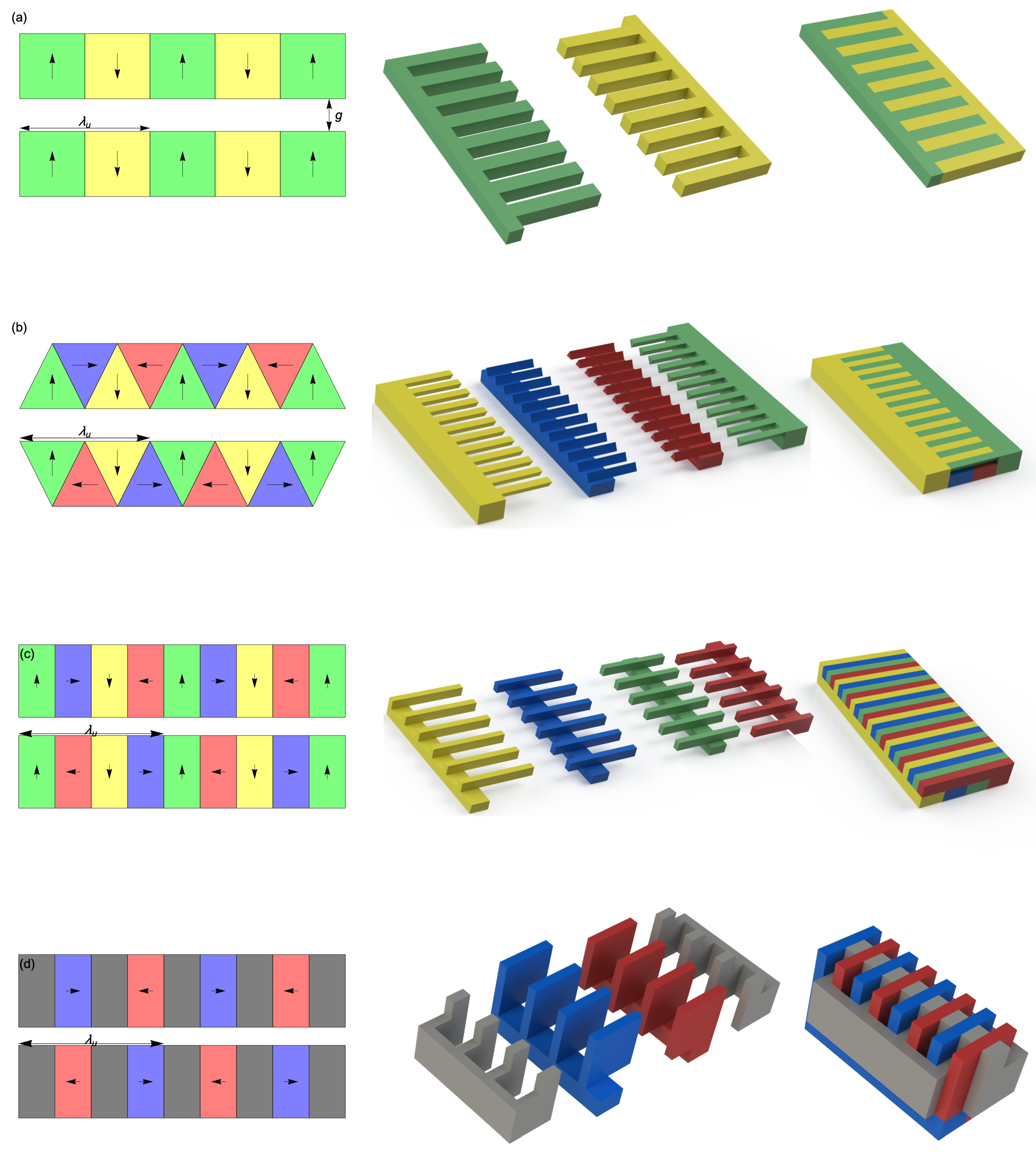
Figure 2.
Mean, absolute fields, , for different Halbach geometries as a function of gap size, normalized to , based on Radia simulations.
Figure 2.
Mean, absolute fields, , for different Halbach geometries as a function of gap size, normalized to , based on Radia simulations.

© 2019 by the authors. Licensee MDPI, Basel, Switzerland. This article is an open access article distributed under the terms and conditions of the Creative Commons Attribution (CC BY) license (http://creativecommons.org/licenses/by/4.0/).
Share and Cite
MDPI and ACS Style
Majernik, N.; Rosenzweig, J. Design of Comb Fabricated Halbach Undulators. Instruments 2019, 3, 58. https://doi.org/10.3390/instruments3040058
AMA Style
Majernik N, Rosenzweig J. Design of Comb Fabricated Halbach Undulators. Instruments. 2019; 3(4):58. https://doi.org/10.3390/instruments3040058
Chicago/Turabian StyleMajernik, Nathan, and James Rosenzweig. 2019. "Design of Comb Fabricated Halbach Undulators" Instruments 3, no. 4: 58. https://doi.org/10.3390/instruments3040058