Article

Applications and Perspectives of Ultrasonic Multi-Gas Analysis with Simultaneous Flowmetry

1
Aix Marseille Université, CNRS/IN2P3, CPPM, Marseille, France
2
Department of Anaesthetics, Morriston Hospital & Swansea University, Swansea SA6 6NL, UK
3
CERN, 1211 Geneva 23, Switzerland
4
Faculty of Science, Aix Marseille Université, Marseille, France
5
High Energy Physics Division, B.P. Konstantinov Petersburg Nuclear Physics Institute, 188300 St. Petersburg, Russia
6
Department of Physics, Oxford University, Keble Road, Oxford OX1 3RH, UK
7
Department of Physics, Cambridge University, J.J. Thomson Avenue, Cambridge CB3 0HE, UK
8
Faculty of Mechanical Engineering, Czech Technical University, Technická 4, 166 07 Prague 6, Czech Republic
*
Author to whom correspondence should be addressed.
Instruments 2021, 5(1), 6; https://doi.org/10.3390/instruments5010006
Submission received: 30 November 2020 / Revised: 6 January 2021 / Accepted: 8 January 2021 / Published: 12 January 2021

Abstract

:
We have developed ultrasonic instrumentation for simultaneous flow and composition measurement in a variety of gas mixtures. Flow and composition are respectively derived from measurements of the difference and average of sound transit times in opposite directions in a flowing process gas. We have developed a sound velocity-based algorithm to compensate for the effects of additional gases, allowing the concentrations of a pair of gases of primary interest to be acoustically measured on top of a varying baseline from ‘third party’ gases whose concentrations in the multi-gas mixture are measured by other means. Several instruments are used in the CERN ATLAS experiment. Three monitor C3F8, (R218), and CO2 coolant leaks into N2-purged environmental envelopes. Precision in molar concentration of better than 2 × 10⁻⁵ is routinely seen in mixtures of C3F8 in N2 in the presence of varying known concentrations of CO2. Further instruments monitor air ingress and C3F8 vapor flow (at high mass flows around 1.1 kg s−1) in the 60 kW thermosiphon C3F8 evaporative cooling recirculator. This instrumentation and analysis technique, targeting binary pairs of gases of interest in multi-gas mixtures, is promising for mixtures of anesthetic gases, particularly in the developing area of xenon anesthesia.

1. Introduction

Continuous, real-time precision measurements of relative concentration of binary pairs of gases are required in many applications. The presence of other gases can however cause ambiguities in the measurement: a particular measured sound velocity can be the result of varying combinatorial concentrations of additional gases. Custom ultrasonic (“sonar”) instruments have been developed [1] for real-time monitoring and measurement of binary gas mixtures in the ATLAS experiment at the CERN Large Hadron Collider (LHC). The ATLAS particle physics detector consists of a series of concentric sub-detectors, including a silicon charged particle tracking detector located near the LHC proton beam collision point. The silicon tracker is evaporatively cooled using octafluropropane (R218: C3F8) and CO2, operating below −10 °C to reduce the effects of radiation damage. Three ultrasonic instruments monitor coolant leaks into the nitrogen-purged envelopes surrounding the silicon tracker. Gas from these envelopes is continuously aspirated into these devices, as illustrated in Figure 1.
Two further instruments form part of the control system of the 60 kW thermosiphon (TS) C3F8 recirculator which exploits the 92 m depth of the ATLAS experimental cavern at the CERN LHC [2] to obtain enough hydrostatic pressure to circulate liquid C3F8 to the detector without the need for pumps or compressors in the primary C3F8 circuit. One of these instruments is an angled acoustic path flowmeter measuring the C3F8 vapor flow (typically around 1.1 kg s−1) returning to the above-ground condenser while the other detects and eliminates (‘degasses’) any ingressed air from the condenser. The five ultrasonic instruments form part of the automated control system of the ATLAS experiment.

2. Materials and Methods

2.1. The Instrumentation and Its Operating Principle

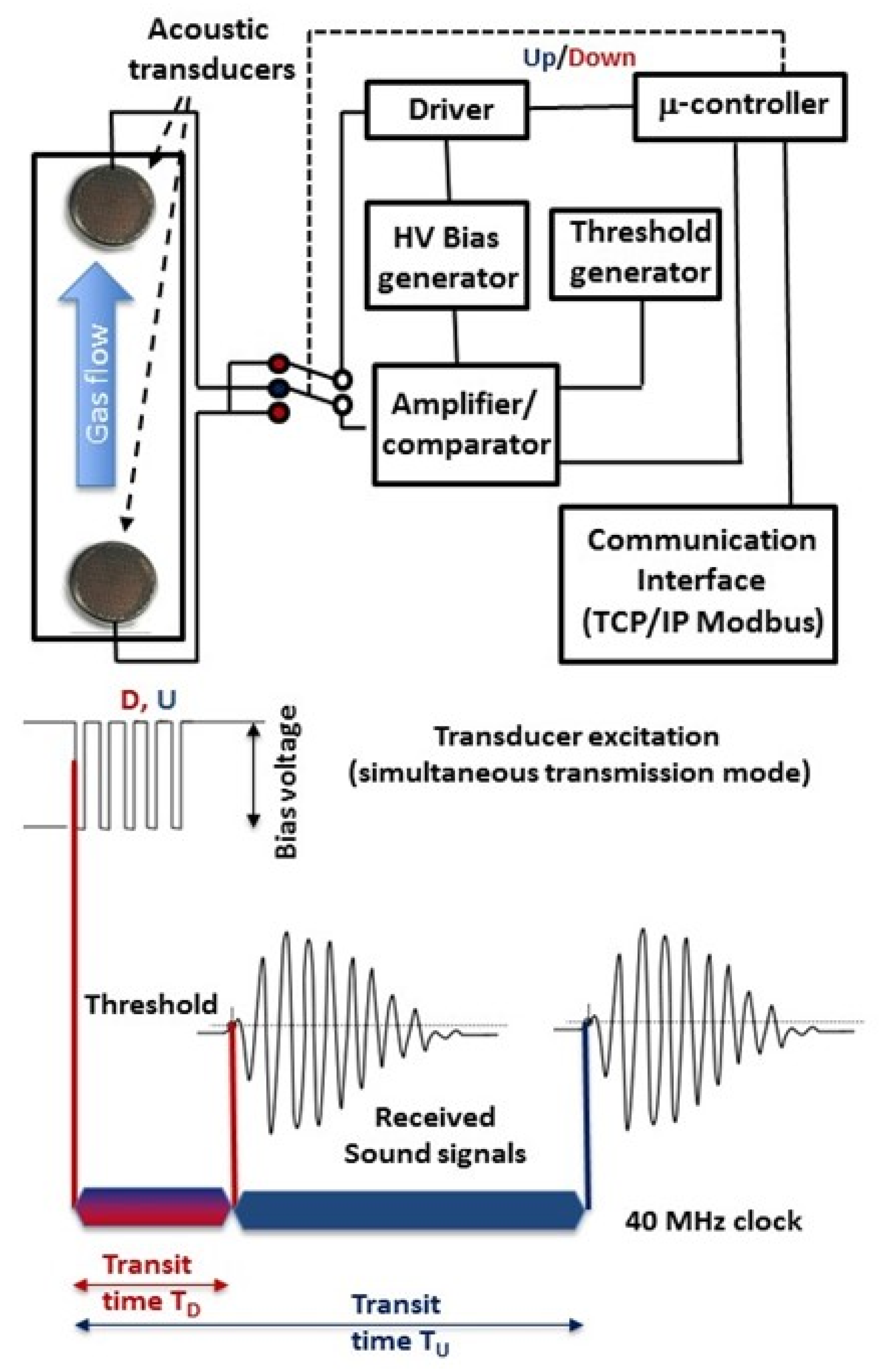
The instruments contain facing pairs of SensComp® model 600 50 kHz capacitive ultrasonic transducers [3] excited by 300→0 V square pulses, generated from low-voltage precursors, as illustrated in Figure 2.
Two 40 MHz transit time clocks are started synchronously with the leading edge of the first pulse transmitted in each direction and are stopped when the signal received at the other transducer crosses a user-definable threshold. The measured transit times TD and TU respectively refer to sound transmission aligned with the direction of gas flow (or at an acute angle, α, to it, in the case of an angled crossing flowmeter), or opposed to the direction of gas flow (or at an oblique angle, {180° −α}, to it. Bi-directional transmission allows simultaneous measurement of the gas flow (from TD, TU transit time differences) and sound velocity (from their average). Since the sound velocity in a gas mixture at known temperature and pressure depends on the molar concentrations of its components it can be compared in real-time to a stored concentration vs. sound velocity database previously generated using data from theoretical models [4] or measurements made in calibration mixtures.

2.2. Gas Flow and Mixture Analysis Algorithms

The gas flow and mixture analysis algorithm aims to accurately compute the molar concentrations of two gases of primary interest in a flowing process gas that may also contain known concentrations of other contaminants. The algorithm uses on-line bi-directional transit times measured in the flowing process gas together with its temperature, pressure, and the concentrations of known contaminants.

2.2.1. Physical Base for Gas Flow Measurements

The volume flow, V, (m3 s−1) measured in an acoustic flowmeter is usually expressed in its simplest form as
V = A · L ( T U     T D ) 2 ( T U · T D )
where L (m) is taken as the distance between transducers, A (m2) is the area of the tube and TD, TU are the transit times respectively measured in directions parallel and opposed to the gas flow direction. The sound velocity, c, (m s−1) is usually also inferred from TD, TU as
c = L ( T U   +   T D ) 2 ( T U · T D )
In practice, Equation (1) is naïve, since it assumes that gas is moving axially over the entire acoustic ‘line-of-sight’ L, whereas in a real instrument some gas will be static or even moving orthogonally to the main gas flow in a (preferably small) component, L’, of the total acoustic path length L.
Higher precision flowmetry can be achieved with algorithms that recognize that the time difference TUTD from which flow velocity is calculated only applies to a subset of the acoustic path where the gas is moving axially, whereas the speed of sound, applies over the whole gas volume.
With this in mind, Equation (1) may be recast as
V =   A · c ( c · T U     ( L + L ) )   ( c · T U     L )                                      
and also as
V =   A · c ( ( L + L )     c · T D ) ( c · T D     L )                                        
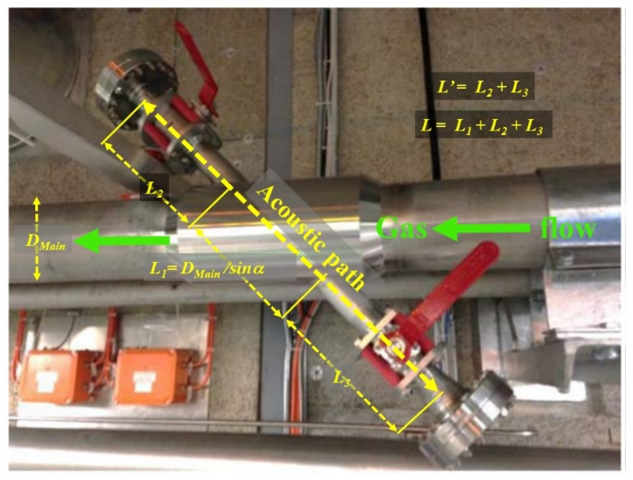
The length of the component L’, of the acoustic path length in which gas is not moving along the acoustic axis is best calculated from computational fluid dynamics studies. We have performed an extensive set of studies for flowmeters in several geometries [1], including that of a high flow 45° angle-crossing flowmeter illustrated in Figure 3. In this device TU and TD are measured in opposite directions at 45° to the direction of gas flowing in a horizontally-mounted 131 mm diameter main tube. The total acoustic path L is composed of component lengths;
DMain/sinα, (α = 45°); where the gas is in laminar motion in the main tube of internal diameter DMain;
L’; the combined acoustic path length in the two acoustic side arms where the gas is considered static.
Adapting Equation (3a,b) to this particular geometry, the expressions for volumetric flow become
V =   A · c ( c · T U     D M a i n sin α     L ) cos α   ( c · T U   L )  
and
V =   A · c (   D M a i n sin α   +   L     c · T D ) cos α   ( c · T D   L )  
where A is the cross-sectional area of the main flow tube.
The ultrasonic transducers are placed out of the main flow tube in 50 mm diameter side arms to minimize turbulence and pressure drop. Quarter-turn ball valves with 40 mm diameter orifices allow the sound to pass but can be closed for transducer access without interrupting the C3F8 vapor flow or exposing it to air pollution. Pressure transducers and thermistors monitor each side arm to allow the density of the circulating C3F8 vapor to be calculated for logging mass flow. Results obtained with the use of this flowmeter are discussed in Section 3.1.
Figure 4 illustrates another—compact—acoustic cell implementation for simultaneous flowmetry and gas mixture analysis in xenon-based anesthesia. Two 16mm diameter 200 kHz piezoelectric transducers are spaced by 8.2 cm, in a flowmeter developed for gas flows up to 30 L min−1. Effort is taken to maximize the L1/L ratio—here 93%. Gas flows through a 10 mm diameter central tube of length L1 (77 mm), being axially aligned over most of the acoustic path length L (82 mm), but must turn through 90° as it enters and exits the central tube through lateral access ‘rings’. In this implementation (shown with a prototype in standard copper tubing components) the spacings L and L3 are chosen to make the ring areas; (π × 10 × 2.5) mm2 similar to the cross-sectional area of the central tube.
It is interesting to compare the acoustic cell geometry of Figure 4 with the Gill/North American Drager anesthetic flowmeter (as used in the North American Drager Narkomed GS and 6000 anaesthesia workstations) operating over the flow range 0–120 L min−1 (Figure 5). The flow range requires low pressure drop (~3 mbar @ 60 L min−1) but has greater acoustic complexity, using sound mirrors and flow deflectors. The acoustic path in axially-moving gas is around 1.8 cm in a total acoustic path length of 8 cm. for an L1/L ratio of 23%.

2.2.2. Physical Base for Gas Mixture Analysis

The gas analysis algorithm is based on the generalized equation for sound velocity, c, in a gas
c = γ R T M
where R is the molar gas constant (8.314 J∙mol−1∙K−1) and T is the absolute temperature (Kelvin). The adiabatic index γ for the mixture is given by the ratio of the weighted sums of molar specific heat at constant pressure ( C p i ) to that at constant volume ( C v i ) of the n components
γ m =   C p m C v m = i w i C p i i w i C v i
where wi are the molar fractions of the components (i = 1→n). Similarly, the molar mass, M, of the mix (kg mol−1) is given by the weighed sum of the molar masses of each component, Mi
M = i w i M i
so that Equation (5) may be recast as
c = i w i C p i i w i C v i R T i w i M i
Figure 6 illustrates as an example the variation of sound velocity with the concentration of C3F8 (molecular weight = 188) in N2 (m.w. = 28) in the range 0 → 1%; a gas pair and concentration range of particular interest in the ATLAS inner tracker cooling application.
The horizontal and vertical indicators added to Figure 6 illustrate the relationship between the uncertainties in precision of the measured sound velocity, c, and the corresponding mixture determination, (mix).
At any concentration of the two components
( m i x ) =   c m
where m is the local slope of the sound velocity vs. concentration curve ([m s−1]/%). For clarity in Figure 7 the ordinate and abscissa have been reversed. In operation the concentration is inferred from the measured sound velocity. At any measured sound velocity the corresponding uncertainty on the mixture is then given by
( m i x ) = c · m  
where m’ is local the slope of the concentration vs. sound velocity vs. curve (%/[m s−1]).
Our instruments give a typical sound velocity measurement error of ±0.025 m s−1, due to the following contributing systematics:
±0.1 °C in gas temperature;
±1 mbar in gas pressure;
±0.1 mm in transducer spacing, based on prior calibration in at least two pure gases using the prescription of §2.3;
±25 ns transit clock frequency.
In the example shown in Figure 6 the average slope of the sound velocity vs. molar concentration curve is around −12.25 m s−1 per percent of C3F8 in the range of interest of 0–1% molar C3F8. The ±0.025 m s−1 instrument uncertainty in sound velocity results in a corresponding mixture uncertainty of ±2 × 10⁻⁵. Over this narrow range the variation of sound velocity with C3F8 concentration can be fitted as linear, requiring only two fit parameters.
In other applications with a larger dynamic range of variation of the two principal gases, higher order polynomials are required to accurately find their concentrations from variations in sound velocity. One of these is the ATLAS ‘degassing sonar’ (Figure 1) which detects and eliminates ingressed air from the C3F8 TS recirculator. It is mounted with its air collection tank above the condenser, at the highest point (also the lowest temperature and pressure region of the TS, with the condenser typically operating in the range {−40 → −60° C; 870 → 300 mbarabs}) where non-condensing air would tend to accumulate, increasing the measured sound velocity. Such undesirable accumulation would increase the condenser pressure, eroding the pressure differential needed to return the required mass flow of 1.1 kg s−1 C3F8 vapor flow to the condenser 92 m against gravity.
When the sound velocity exceeds an operator-definable threshold, equivalent to a certain air concentration, the degassing sonar tube and collection tank are automatically isolated from the condenser vapor volume and evacuated to ‘release’ the incondensable air. The degassing sonar tube is thermally jacketed, typically operating at 20 °C where low pressure C3F8 vapor rising into it from the TS condenser can be considered to be in the superheated state.
Figure 7 illustrates the variation of concentration of air in C3F8 vs. measured sound velocity at three different sonar tube temperatures at a pressure of 300 mbarabs. The large dynamic range of interest (0–30% molar) for air infiltration into C3F8 requires quadratic (3-parameter) fits of concentration vs. sound velocity. The axis inversion, compared with Figure 6, avoids the requirement of quadratic root finding that would be necessary in fits of sound velocity vs. concentration. Indeed, where higher order fits are required no analytic solutions might exist. Sound velocity is the measurement variable and the natural choice of abscissa.
As an example from Figure 7, at a measured sound velocity of 122.75 m s−1, corresponding to around 10% air contamination the local curve slope (at 20 °C) obtained by differentiating its polynomial form is around 1.73% air/m s−1: a sound velocity measurement error of ±0.025 m s−1 would yield an uncertainty in air concentration of ±0.04% from Equation (9b).
It is clear that higher precision is possible in gas pairs with a large difference in molecular weight. In the examples of Figure 6 and Figure 7 the differences are around 160 Daltons. In xenon-oxygen based anaesthesia—another field of interest discussed in §5—the difference is 99 Daltons. There however the wide dynamic range of the gases (0–80% Xe in O2) requires a higher order polynomial.

2.3. Instrument Calibration

The acoustic path length and any time delays between the arrival of ultrasound pulses and the stopping of transit time clocks need to be determined to allow the high-precision measurement of the sound velocity, upon which ultrasonic gas mixture analysis ultimately depends. Acoustic path length is traditionally measured by injecting a static gas of known sound velocity into the instrument and measuring the transit time delay.
To accurately measure the total acoustic path, LA, between the ultrasonic transducers a calibration based on two gases (CalG1, CalG2) of sufficiently different molecular weights and sound velocities (CCalG1, CCalG2) is carried out [5], giving
L A = c C a l G 1 · c C a l G 1 · ( t t C a l G 1 t t C a l G 1 ) c C a l G 2 c C a l G 1
where the measured transit times ttCalG1 and ttCalG2 in the two calibration gases themselves include a component ttoffset: the delay between the arrival of an acoustic pulse at a receiving transducer and its electrical signal passing a detection threshold (Figure 2)
t t o f f s e t = c C a l G 1 · t t C a l G 1 c C a l G 2 · t t C a l G 2 c C a l G 2 c C a l G 1
This delay must be subtracted from measured transit times in the process gas to accurately calculate sound velocity for comparison with a concentration vs. sound velocity database. The sound velocities cCalG1 and cCalG2 used in the calibration procedure should correspond to the temperature in the acoustic cell and can be found for a large range of common gases from—for example—NIST-REFPROP [4]. The calibration gases can of course also be the pure components of the process gas mixture of interest, representing the opposite ends of the expected transit time spectrum.

2.4. Database Operation

2.4.1. Data Generation and Storage—3-D Dataspace

For the pair of gases AB of primary interest a (sound velocity, concentration) grid dataspace is generated, covering the expected ranges of the primary gas mixture AB, the process temperature and pressure and (where present) independently-measured concentrations, wi, of any known third-party gas(es). The effect on the AB mixture sound velocity due to the presence of known additions of third-party gases is calculated using Equation (8) using the C p i   and C v i data for all the individual gas components derived from equations of state: e.g., in [4].
The (AB sound velocity, concentration) data is stored as a series of polynomial fit parameters ay of the form
% c o n c ( A _ i n _ B ) = a · c n + b · c n 1 + + x · c + y
calculated at the intersections of ‘grids’ of values of temperature, pressure and “third-party” gas concentrations. Such “third party” gases are of importance in the ATLAS application. The ATLAS experiment uses large volumetric flows of CO2 in regions outside of the inner silicon tracker. The N2-purged environmental envelopes of the ATLAS “SCT” silicon tracker sub-detector are particularly susceptible to CO2 ingress; under some operational conditions, including CO2 purge of regions immediately surrounding the ATLAS silicon tracker, one of the four SCT N2—purged envelopes can routinely see up to several thousand ppm of ingressed CO2.
The polynomial fit parameters of Equation (12) can be thought of as being stored in ‘cans’ suspended in a multidimensional grid. In an example from the ATLAS application (Figure 6) C3F8 represents gas A and N2 gas B. The dynamic (alarm) ranges of interest for C3F8 coolant leak concentrations into N2 lie in the molar interval 0–0.1%. Over this relatively short range linear (two-parameter) fits based on 100 sound velocity—concentration points (for example in Figure 6: generated in 10−5 concentration increments) have been found sufficiently precise.
These parameters are generated using Equation (8) with pure gas Cp and Cv data from [4] on intersections of a 3-D {T, P, ppmCO2} grid covering:
13–25 °C (0.5 °C step: n_T = 25 points);
900–1100 mbarabs (20 mbar step: n_P = 11 points);
0–10,000 ppm CO2 (1000 ppm step: n_CO2 = 11 points);
giving a database of 6050 stored parameters (2·n_T·n_P·n_CO2). In this application CO2 concentration is measured with a Telaire®® infra-red sensor [6] of 10,000 ppm full scale output.
In practice—since the temperature, pressure and CO2 concentration (measured simultaneously with the acoustic transit times) will fall between the grid intersections—a multi-step interpolation is used to adjust the parameters of Equation (12) to correspond to the measured process variables, as discussed in the following section.

2.4.2. Data Interpolation and Concentration Finding

Figure 8 illustrates the three-stage interpolation of fit parameters of {C3F8 in N2} vs. sound velocity generated and stored in intersection ‘cans’ (•) on a 3-D {T, P, ppmCO2} grid. The 8 nearest grid points in (T, P, ppmCO2) space are chosen to define the smallest cuboidal volume encompassing the process measurables {Pmeas, Tmeas, CO2_meas}. For clarity these eight points are represented as projections on the (P,T), (P,ppmCO2), and (ppmCO2,T) facets in Figure 8a.
The interpolation proceeds from the start positon of Figure 8a in three steps:
(i) 
The {C3F8 in N2} vs. sound velocity fit parameters held in the eight cans depicted in Figure 8a are interpolated to intermediate values corresponding to Tmeas at grid pressures immediately above and below Pmeas as shown in Figure 8b, collapsing the search at the core of the grid to a 2-D search between four grid points on a square in {P, ppmCO2} space;
(ii) 
These intermediate {C3F8 in N2} vs. sound velocity fit parameters are then interpolated along the orthogonal (P) direction to calculate new intermediate parameters corresponding to Tmeas as shown in Figure 8c, further collapsing the core search to a final interpolation between two2 adjacent grid points on a line in the {ppmCO2} direction;
(iii) 
The final interpolation of intermediate {C3F8 in N2} vs. sound velocity fit parameters is then made along the {ppmCO2} direction obtaining the final parameters corresponding to {Pmeas,Tmeas,CO2meas}: Figure 8d.
From these final parameters the relative concentrations of the C3F8 and N2 components in the mixture of primary interest are calculated. Results from the analysis of a C3F8/N2 gas mixture on top of a known varying concentration of CO2 are discussed in Section 3.2.
Clearly, if no third-party gas is present, the interpolation is reduced to a two-step process starting with four grid points in {T,P} space. For each additional process parameter the database acquires an additional dimension, and becomes cubic (Figure 8), tessaractic or pentaractic (four or five process parameters respectively), or higher-dimensional. The interpolation strategies for these multidimensional dataspaces are discussed in Section 4.1.

3. Results

3.1. Flowmetry

Results obtained during the pre-commissioning and use of the angled flowmeter of Figure 3 are discussed in this section.
The angled flowmeter demonstrated linearity in air flows up to 10 m s−1 (135 L s−1) pre-installation, with rms precision of ±2.3% of full scale (Figure 9). High volumetric airflows were obtained by running compressed air from the standard supply pressure of 8 bar through a Venturi mounted upstream of the device, drawing a high flow of room air. The flow, calculated according to Equation (4a,b) was compared with that measured in an Amprobe TMA10A anemometer.
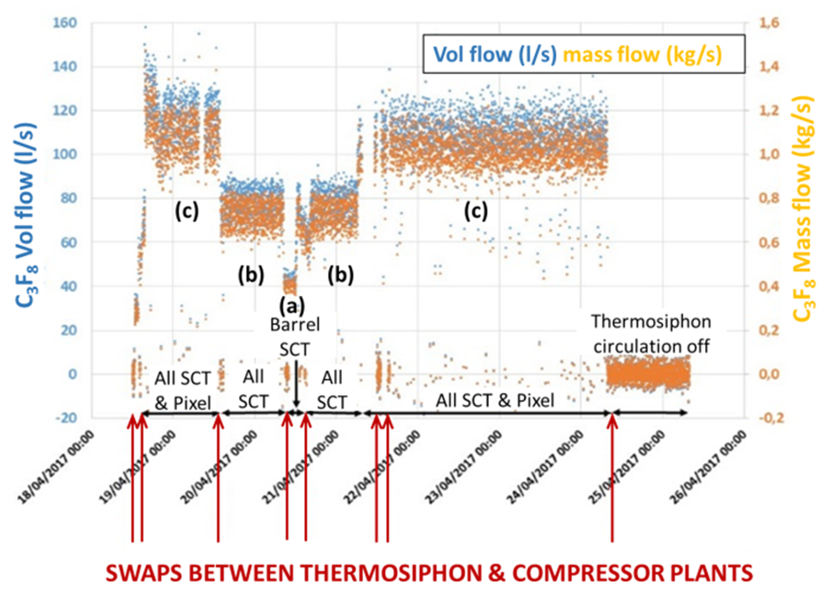
Figure 10 illustrates flowmeter measurements in C3F8 vapor during commissioning tests of the ATLAS TS in April 2017. During these commissioning tests, the ATLAS ‘SCT’ and ‘pixel’ sub-detectors were evaporatively cooled with C3F8 at power levels up to 60 kW. With only the ATLAS ‘barrel SCT’ sub-detector powered (a) the dissipation of nearly 22 kW required the circulation of around 0.4 kg s−1 of C3F8. The corresponding mass flow with the full SCT (‘barrel’ and ‘endcaps’) powered (b) was around 0.75 kg s−1, while that required to cool the combined SCT and Pixel trackers (c) at a dissipation of around 60 kW was 1.1 kg s−1. The mass flow resolution of the ultrasonic flowmeter during these runs was around ±0.05 kg s−1. During the commissioning tests repeated transitions (cold ‘swaps’: red arrows in Figure 10) were made between the TS and the compressor-driven recirculator that it has since relegated to the status of a back-up system. During these swaps the temperature fluctuations on powered silicon modules were less than 2 °C. Note: during compressor operation zero flow is seen in the C3F8 vapor return line to the condenser since the vapor is redirected to the compressor inputs.

3.2. Analysis of a Pair of Gases of Primary interest in the Presence of Third-Party Gas Contamination

Figure 11 illustrates measurements of C3F8 concentration seen in the N2-purged volume surrounding the ATLAS ‘pixel’ silicon tracker sub-detector during a global restart of its C3F8 evaporative cooling system in October 2020. This followed a short cooling shut down. The sonar system can comfortably follow small C3F8 concentration changes in the ATLAS environment of the order of 2 × 10⁻⁵. The ‘overshoot’ following the restart is due to a higher evaporation pressure being initially run in some of the 88 cooling circuits, a few of which have small leaks into their shared environmental volume.
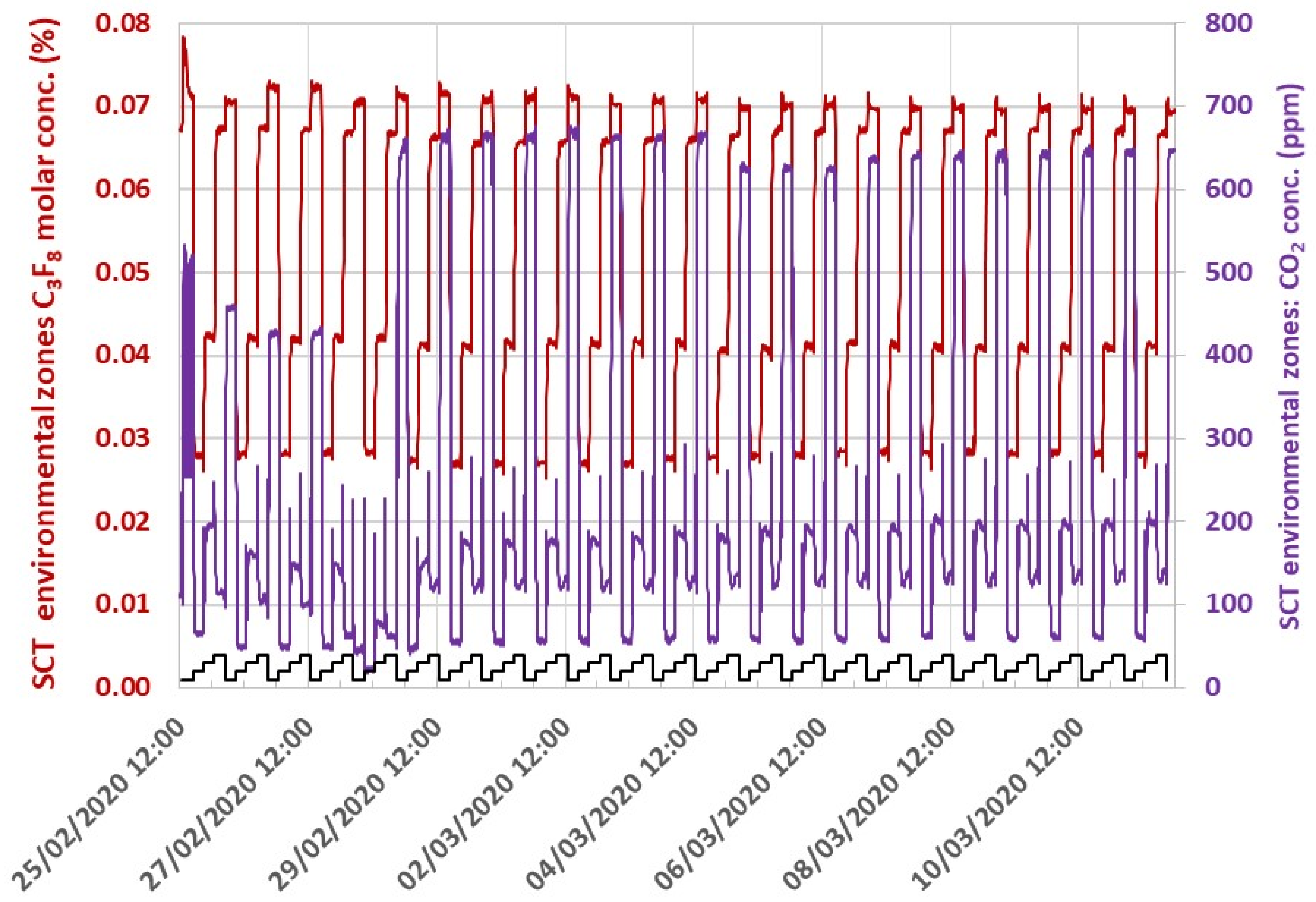
Figure 12 illustrates measurements of C3F8 concentration seen in the N2-purged zones of four different environmental volumes of the ATLAS ‘SCT’ silicon tracker, which are sequentially monitored in a 16-h supercycle by aspiration through a single sonar instrument. These zones have varying permeability (and hydrostatic collectivity) to CO2 ingress from the exterior; the sources being other sub-systems of the ATLAS experiment employing CO2 in active gas mixtures for charged particle detection. Ingressed CO2 concentration is monitored with a Telaire® infrared monitor [6] fitted inside a small gas enclosure mounted in series with the sonar tube. This instrument pairing allows unambiguous C3F8 concentration measurement on top of a varying known CO2 concentration. During the measurement period shown in Figure 12 the ingressed CO2 concentration underwent a step-increase in one of the four SCT zones (February 29) due to external manipulations of CO2 systems in other parts of ATLAS, while the C3F8 leak rate into each zone (due to small coolant leaks) remained stable.
In Figure 12, the relative concentrations of a primary gas pair of interest (C3F8/N2) are demonstrably measured in four mixture streams—each containing different, variable, known concentrations of a third gas—the analysis using a data base including that gas, constructed using the formalism of Equations (6)–(8) with the interpolation technique illustrated in Figure 8. The analysis algorithm was implemented in the Simatic WINCC-OA package [7], which is the SCADA standard for large detector control systems at the CERN Large Hadron Collider.

4. Discussion

4.1. Extensions into > 3-D Process-Spaces

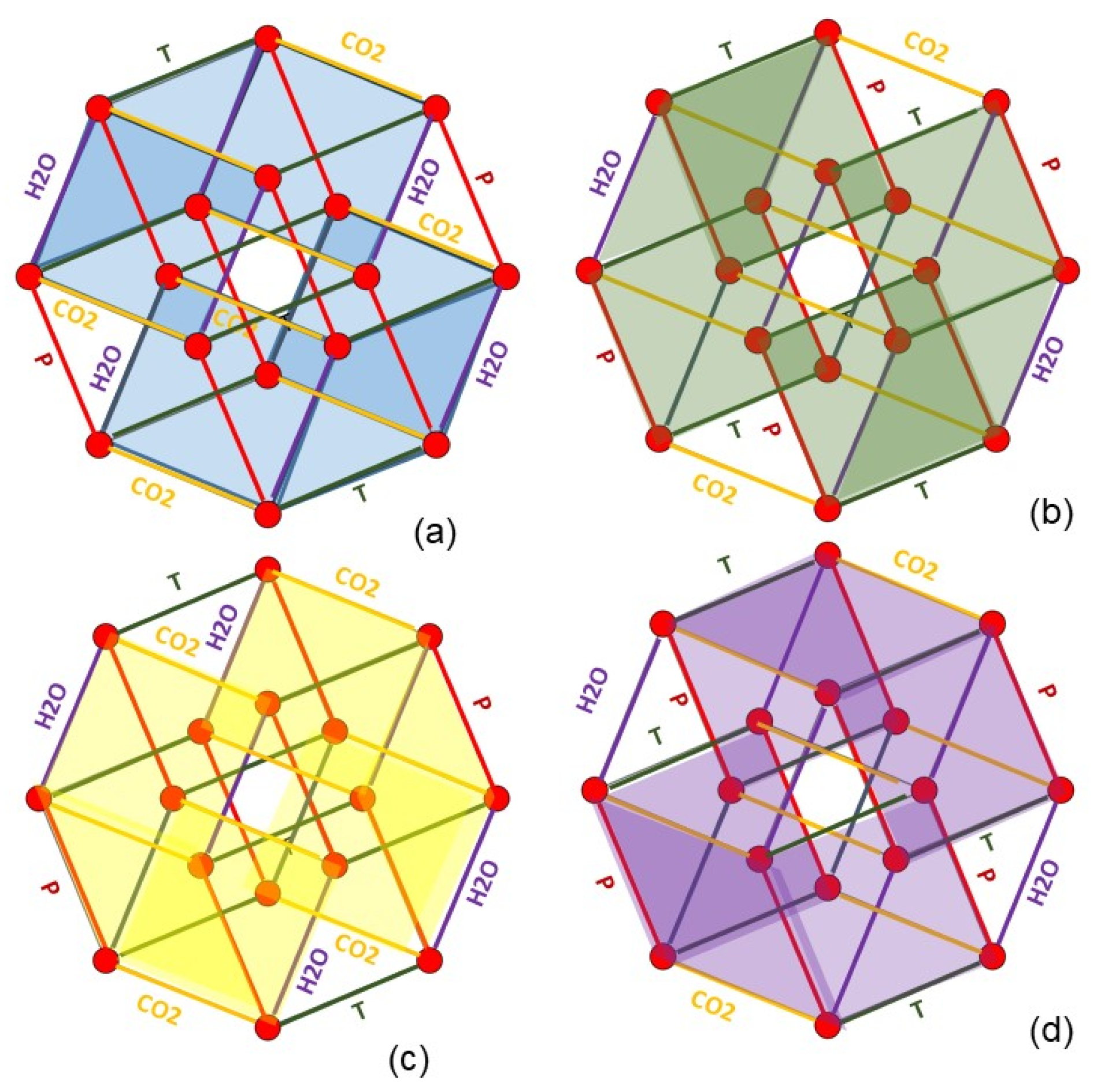
Figure 13 and Figure 14 illustrate the interpolation of sound velocity concentration data for a gas pair of primary interest in the presence of four process variables: temperature, pressure, CO2, and humidity. This is an interpolation of fit parameters calculated at the intersections of a four-dimensional grid which can be illustrated in a Coxeter B4 projection of the related tesseract.
It can be seen in Figure 13 that opposite faces of the tesseract are formed by four pairs of cubes (color-coded (a)–(d) for identification). Three interpolations can be made within these cubes—in the same way as illustrated in Figure 8—with the final interpolation made along the dimension that separates them. It is evident that the interpolation can be made in four different sequences, to arrive at the same result. These paths which are shown by extraction and reduction in Figure 14a–d.
In the case of a 5-D database, for example including a third measured contaminant gas, the interpolation is from a conceptual penteract {A, B, C, D, E} whose opposite faces are five pairs of tesseracts. Each tesseract can be represented by a cube pair so that the final interpolation has an extra (fifth) step. There are 10 ways of approaching the four cubes, from which the final interpolation can then be made in two ways.
Figure 8 and Figure 13, Figure 14 and Figure 15 illustrate the interpolations from regions of interest defined by the nearest grid points in dataspace. Multidimensional parameter interpolation (by sequential cube extraction) is less of a problem than the geometric growth in the number of data-points in the extradimensional databases. With fine grid mesh fit parameter interpolations can be linear, but this leads to a large database, with a total number of parameters given by
D B   s i z e   ( d a t e   p o i n t s )   =   N o ·   p r i m a r y   f i t   c o e f f s ·   R o I T   d _ T ·     R o I _ P d _ P ·   R o I _ C o n c ·   b k d   g a s   1 d _ C o n c ·   b k d   g a s   1  
where RoI_T, _P etc. are the ranges of interest of the process variables and d_T, _P are their corresponding step sizes or granularities. Database size may clearly be reduced by increasing the granularity in some dimensions (or eliminating them altogether) by applying a physical law rather than a short-range interpolation. One example would be in the temperature dimension using the relation
c t 1 = c t 0 t 1 t 0
where c t 1 and c t 0 are the sound velocities at absolute temperatures t1 and t0, respectively.

5. Conclusions and Perspectives

We describe several implementations of custom ultrasonic instrumentation for real-time monitoring of flow and binary gas mixtures. One instrument configured as an angled flowmeter demonstrated a precision better than ±2.3% full scale for air flows up to 10.5 m s−1 and a resolution better than ±0.05 kg s−1 in C3F8 flows around 1 kg s−1. Other instruments have demonstrated a precision in composition measurement of ±2 × 10⁻⁵ in N2/C3F8 mixtures in a leak detection environment.
Although ultrasonic gas analysis is primarily seen as a binary gas analysis tool, we have demonstrated that it can be successfully used with higher order gas mixtures if the concentration of the additional component(s) is known from other sources and the reference database also includes their thermodynamic data. We have illustrated use of the algorithm for a N2/C3F8 primary mixture with known varying concentrations of CO2.
This analysis approach could find use in various industrial and medical applications were accurate and simultaneous real-time flow and gas analysis are required in a multi-process gas environment. One example is the monitoring of anesthetic gas mixtures. In conventional anesthesia these are often ternary mixtures of oxygen and nitrogen, or oxygen and nitrous oxide; with 0−10% additions of sevoflurane or similar vapors, together with the additional presence of CO2 and water vapor.
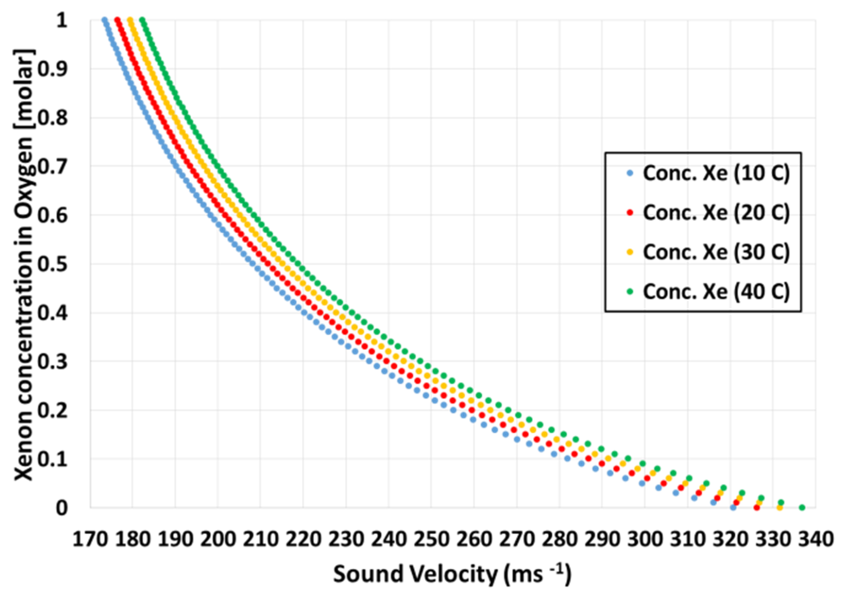
In the developing area of xenon-based anesthesia the molecular weight difference (Xe/O2: m.w. 131/32) between the primary components is more advantageous. Figure 16 illustrates the composition/sound velocity dependence at atmospheric pressure for several temperatures. The wide clinical range (here from 20 to 100% O2) typically requires a fifth order polynomial representation. The average gradient over the range is around 0.52% per m s−1. From Equation (9a) we see that a target precision of ±0.1% Xe in O2 implies a sound velocity measurement precision of ±0.19 m s−1.
While precisions of 0.025–0.05 m s−1 are achieved in the CERN instruments using exposed foil capacitive transducers [3], such precision is more challenging over shorter acoustic paths using piezoelectric transducers mounted in sterilizable enclosures and having reduced acoustic coupling to gases. Piezoelectric transducers can have significant emission delays (10–100 μs) relative to their electric excitation signals, making the multi-gas calibration protocol of Equations (10) and (11) indispensable. Preliminary ultrasonic studies in Xe/O2 blends were recently presented [8]. New custom ultrasonic instrumentation is under development to provide simultaneous flowmetry and Monitoring of xenon concentration in anesthesia and to reduce wastage in the post-operative environment, by allowing xenon to be extracted from recovered breathing gas mixtures for recycling.

Author Contributions

Conceptualization: J.D., G.H., D.R., and V.V.; Methodology, J.D., M.D., G.H., S.K., and D.W.; Software, K.N., S.K., D.W., R.F., and A.R.; Validation, J.D., M.D., G.H., and D.R.; Formal analysis, G.H., J.D., and D.W.; Investigation, all authors; Resources, J.D., G.H., K.N., D.R., A.R., and V.V.; Writing—original draft preparation, G.H.; Writing, review, and editing, all authors; Visualization, M.D. and G.H.; Supervision/project administration, J.D., G.H., K.N., D.R., and V.V.; Funding acquisition; G.H., J.D., K.N., D.R., and V.V. All authors have read and agreed to the published version of the manuscript.

Funding

The CERN-based research was carried out through the participation of the authors in the international CERN-LHC ATLAS collaboration. M. Doubek and V. Vacek also acknowledge support from the Department of Physics of the Faculty of Mechanical Engineering at the Czech Technical University in Prague and through grant MSMT no. 1501601D000 LM2015058.

Institutional Review Board Statement

Not applicable.

Informed Consent Statement

Not applicable.

Data Availability Statement

The data presented in this study are available on request from the corresponding author.

Dedication

This paper is dedicated by the communicating author with gratitude to the memory [9] of his late friend Lawrence C. Lynnworth (1937–2019) of Waltham, MA, USA: author of the classic reference; “Ultrasonic Measurements in Process Control; Theory, Techniques, Applications” (Academic Press, 1989): ISBN 978-0-12-460585-5.

Conflicts of Interest

The authors declare no conflict of interest. The funders had no role in the design of the study; in the collection, analyses, or interpretation of data; in the writing of the manuscript, or in the decision to publish the results.

References

  1. Bates, R.; Battistin, M.; Berry, S.; Berthoud, J.; Bitadze, A.; Bonneau, P.; Botelho-Direito, J.; Bousson, N.; Boyd, G.; Bozza, G.; et al. A combined ultrasonic flowmeter and binary vapour mixture analyzer for the ATLAS silicon tracker. J. Instrum. JINST 2013, 8, P02006. [Google Scholar] [CrossRef] [Green Version]
  2. Battistin, M.; Berry, S.; Bitadze, A.; Bonneau, P.; Botelho-Direito, J.; Boyd, G.; Corbaz, F.; Crespo-Lopez, O.; Da Riva, E.; DeGeorge, C.; et al. The thermosiphon cooling system of the ATLAS experiment at the CERN Large Hadron Collider. Int. J. Chem. React. Eng. 2015, 13, 511–521. [Google Scholar] [CrossRef]
  3. Originally by Polaroid® for Autofocus Cameras: Now Marketed as the SensComp Model 600 Transducer. Available online: http://www.senscomp.com/ultrasonic-sensors/ (accessed on 7 January 2021).
  4. Lemmon, E.; Huber, M.; McLinden, M. REFPROP Standard Reference Database 23, version 9.0; U.S. National Institute of Standards and Technology, Thermophysical Properties Division: Boulder, CO, USA, 2010. [Google Scholar]
  5. Battistin, M.; Berry, S.; Bonneau, P.; Crespo-Lopez, O.; Deterre, C.; Doubek, M.; Favre, G.; Hallewell, G.; Katunin, S.; Lombard, D.; et al. Novel ultrasonic instrumentation developments for real-time monitoring of binary gas mixtures and flow: Description and applications. Sens. Transducers 2016, 207, 4–14. Available online: https://www.sensorsportal.com/HTML/DIGEST/december_2016/Vol_207/P_2878.pdf (accessed on 7 January 2021).
  6. Amphenol Telaire® Infrared CO2 Monitor. Available online: https://www.amphenol-sensors.com/en/telaire (accessed on 20 November 2020).
  7. Siemens Simatic WINCC OA. Available online: https://new.siemens.com/global/en/products/automation/industry-software/automation-software/scada/simatic-wincc-oa.html (accessed on 20 November 2020).
  8. Williams, D.; Hallewell, G.; Chakkarapani, E.; Dingley, J. Real-time measurement of Xenon in a binary gas mixture using ultrasound time-of-flight: A feasibility study. Anesth. Analg. 2019, 129, 985–990. [Google Scholar] [CrossRef] [PubMed] [Green Version]
  9. Hallewell, G.; Lynnworth, L. A simplified formula for the analysis of binary gas containing a low concentration of a heavy vapor in a lighter carrier. In Proceedings of the 1994 IEEE Ultrasonics Symposium, Cannes, France, 31 October–3 November 1994; Volume 3, pp. 1311–1315. [Google Scholar] [CrossRef]
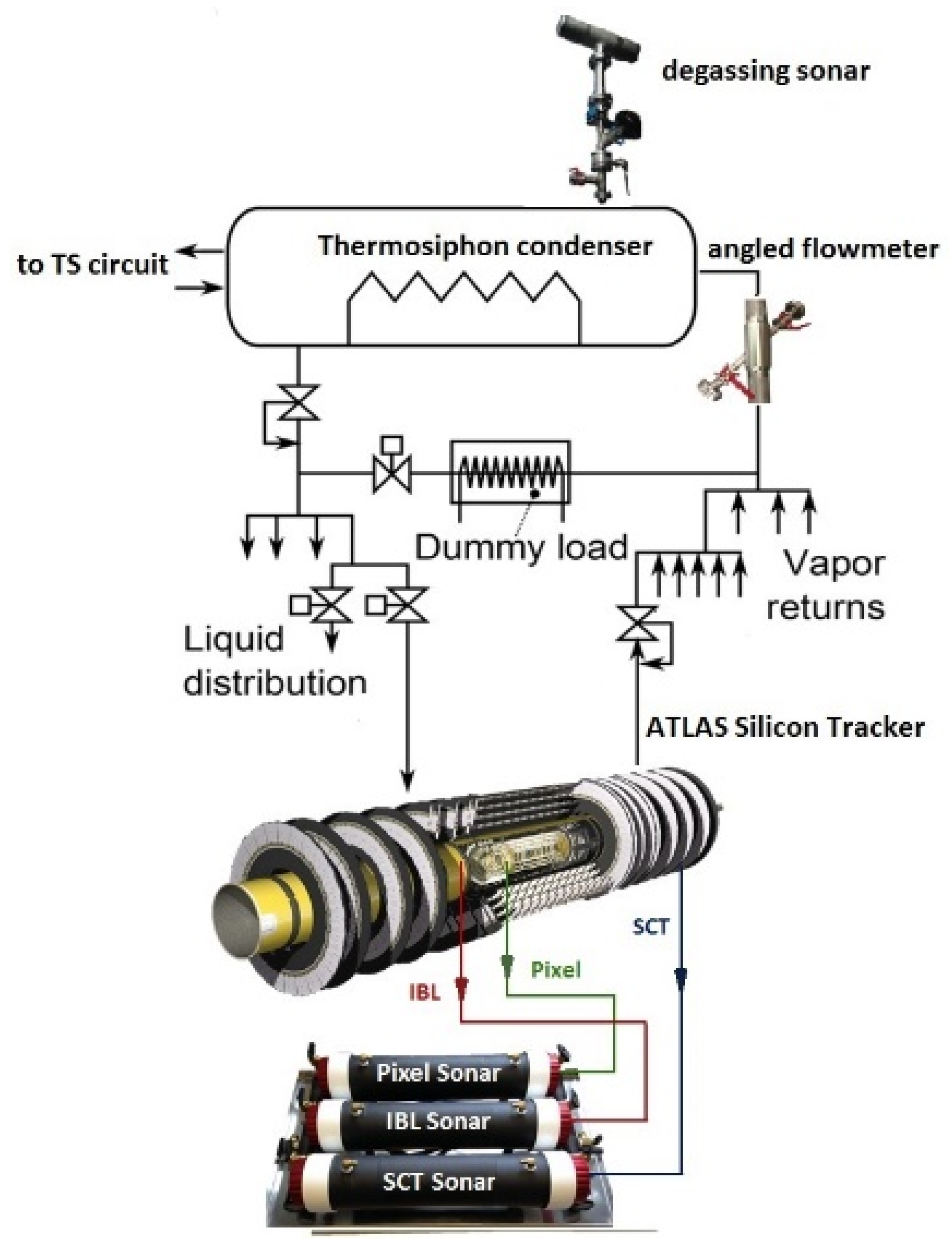
Figure 1. Installations in the ATLAS Inner Detector. Three sonars monitor the N2 envelopes of the Pixel, SCT, and IBL silicon tracker sub-detectors, while a degassing sonar and an angled flowmeter monitor the 60 kW thermosiphon (TS) C3F8 evaporative coolant recirculator.
Instruments 05 00006 g001
Figure 2. Electronics for ultrasonic transducer excitation and bi-directional transit time measurement.
Instruments 05 00006 g002
Figure 3. Angled ultrasonic flowmeter in the vapor return line of the ATLAS C3F8 thermosiphon (‘TS’) recirculator.
Instruments 05 00006 g003
Figure 4. Geometry of a prototype flowmeter and gas analyzer for xenon-oxygen anesthetic gas mixtures.
Instruments 05 00006 g004
Figure 5. Acoustic cell geometry of the ultrasonic flowmeter used in North American Drager Narkomed GS and 6000 anesthesia workstations.
Instruments 05 00006 g005
Figure 6. Variation of sound velocity with concentration of binary C3F8/N2 mixtures in the range 0 → 1% C3F8 at 1 barabs. The added vertical and horizontal indicators illustrate the relation between the uncertainties in measured sound velocity and mixture determination [1].
Instruments 05 00006 g006
Figure 7. Sound velocity dependence on air concentration in C3F8 vapor at three temperatures of the degassing sonar and a pressure of 300 mbarabs.
Instruments 05 00006 g007
Figure 8. Schematic showing the three-step successive interpolation of sound velocity vs. {C3F8 in N2} concentration fit parameters held in ‘cans’ (•) at the nearest stored grid intersections to determine those corresponding to the measured {T, P, CO2 contamination} process conditions. See text for explanation of interpolation steps (ad).
Instruments 05 00006 g008
Figure 9. Volumetric flow measured in the 45° angled ultrasonic flowmeter compared to that measured in an Amprobe TMA10A anemometer. Pre-installation calibration test in air.
Instruments 05 00006 g009
Figure 10. C3F8 volumetric flow and mass flow measured ultrasonically in the vapor return line of the ATLAS TS under different load conditions (ac): see text.
Instruments 05 00006 g010
Figure 11. Variation of C3F8 concentration seen in N2-purged environmental volume surrounding the ATLAS ‘pixel’ silicon tracker sub-detector during a global restart of its C3F8 evaporative cooling system on 20 October 2020.
Instruments 05 00006 g011
Figure 12. Variations of % molar C3F8 (red) and ppmCO2 concentrations (violet) seen in four sequentially-monitored N2-purged zones surrounding the ATLAS SCT silicon tracker (partitions indicated by repeating ‘valve state’ staircase (black): 1—“Barrel bottom” → 2—“Side C” → 3—“Side A” → 4—“Barrel top” → 1…).
Instruments 05 00006 g012
Figure 13. Tesseract (Coxeter B4 projection) showing the four (color-coded) possible initial three interpolation routes for {%Gas_1 in Gas_2} concentration vs. sound velocity polynomial fit parameters within the 4-D {P,CO2,T,H2O} database (ad): respectively via the {CO2,H2O,T}, {T,H2O,P}, {CO2,P,H2O}, and {CO2,P,T} pathways.
Instruments 05 00006 g013
Figure 14. Final interpolation step between {%Gas_1 in Gas_2} concentration vs. sound velocity polynomial fit parameters already interpolated to points within their respective cubes at opposite faces of the {P,CO2,T,H2O} tesseract of Figure 12.
Instruments 05 00006 g014
Figure 15. Penteract (Coxeter B4 projection) illustrating the {A,B,C,D,E} dataspace for five process parameters. An additional final interpolation step (c) is needed between sound velocity vs. {%Gas_1 in Gas_2} concentration polynomial fit parameters already interpolated (a), (b) to points between their respective cube pairs. The dimension of the final interpolation (here, C) depends on the pre-chosen pairs of cubic faces.
Instruments 05 00006 g015
Figure 16. Composition/sound velocity dependence in xenon-oxygen mixtures at atmospheric pressure and several temperatures.
Instruments 05 00006 g016
Publisher’s Note: MDPI stays neutral with regard to jurisdictional claims in published maps and institutional affiliations.