Article

RF Design and Measurements of a C-Band Prototype Structure for an Ultra-High Dose-Rate Medical Linac

1
SBAI Department, Sapienza University of Rome, 00185 Roma, Italy
2
INFN Sezione di Roma, 00185 Roma, Italy
3
SIT—Sordina IORT Technology S.p.A., 36100 Vicenza, Italy
4
INFN Laboratori Nazionali di Frascati, 00044 Frascati, Italy
*
Author to whom correspondence should be addressed.
Instruments 2023, 7(1), 10; https://doi.org/10.3390/instruments7010010
Submission received: 23 December 2022 / Revised: 15 February 2023 / Accepted: 17 February 2023 / Published: 22 February 2023

Abstract

:
In this paper, we illustrate the RF design and measurements of a C-band prototype structure for an Ultra High Dose Rate medical linac. (1) Background: FLASH Radiotherapy (RT) is a revolutionary new technique for cancer cure. It releases ultra-high radiation dose rates (above 100 Gy/s) in microsecond short pulses. In order to obtain a high dose in a very short time, accelerators with high-intensity currents (the order of 100 mA peak currents) have to be developed. In this contest, Sapienza University, in collaboration with SIT-Sordina IORT Technology spa, is developing a new C-band linac to achieve the FLASH regime. (2) Methods: We performed the RF electromagnetic design of the prototype of the C band linac using CST STUDIO Suite Code and the RF low power RF test at Sapienza University of Rome. The measurements of the field in the cavity have been done with the bead-pull technique. (3) Results: This device is a nine-cell structure operating on the π / 2 mode at 5.712 GHz (C-band). We report and discuss the test measurement results on a full-scale copper prototype, showing good agreement with CST RF simulations. A tuning procedure has been implemented in order to ensure proper operating frequency and to reach a field profile flatness of the order of a few percent. (4) Conclusions: The prototype of a C-band linac for FLASH applications was successfully tested with low RF power at Sapienza University. The fabrication and ad hoc tuning procedures have been optimized and discussed in the paper.

1. Introduction

Nowadays, a large number of cancer patients, up to 50%, are treated with radiotherapy (RT) [1,2]. A new RT paradigm has been introduced in the medical community since the discovery of the so-called FLASH effect [3], which results in the higher sparing of healthy tissues but maintains the same tumor-killing efficiency. In technical words, this effect increases the therapeutic window. As a consequence, FLASH radiotherapy represents, at the moment, the new frontier in cancer cure. The FLASH effect has been demonstrated in pre-clinical experiments [4,5,6] and in clinical practice but for superficial tumors only [7]. The required average dose rate for the FLASH effect is much higher than that used today in conventional (CONV) RT treatments. In particular, the new required value is well above 100 Gy/s, versus CONV dose rates below 1 Gy/s, and with short beam-on times (<100 ms) and large doses in each pulse (>10 Gy). In the accelerator community worldwide, important efforts have started to allow the availability of radiation sources that can be operated in ultra-high dose-rate modality. For this purpose, many linear accelerators (linac) machines were employed [8,9,10]. Moreover, various existing clinical linacs were modified to perform electron FLASH-RT experiments [11,12,13]. Our research group started in the FLASH radiotherapy field with the first dedicated electron linac termed the ElectronFLASH for low-energy applications. The linac operates in the S-Band frequency of 2.998 GHz in a standing-wave mode, the electron energies produced by the linac can reach 5 MeV or 7 MeV and it has two modes of operation, the FLASH modality and the conventional one. It was commissioned and installed first at the Curie Institute in Orsay, and then in other research centers. The paper which describes the design of this low-energy device was published elsewhere [8,14,15].
More recently, our group started the investigation of a more compact and more cost-effective linac in C-Band for low-energy applications, such as IOeRT. We performed linac’s RF and beam dynamics design at an output electron energy of up to 12 MeV. The accelerating structure is composed of 30 cavities or cells different in geometrical dimensions. In the initial part of the linac, all cells have different lengths (bunching section) in order to accommodate the low energy electron bunch generated from a thermionic cathode (electron gun). In the following part, cells have the same lengths as the electron beam approaches the speed of light.
The main linear accelerator parameters are indicated in Table 1.
Presently, the device has a pending patent and it will be realized and tested for industrial purposes.
In this paper, we present the design and the tests of a prototype of the C-Band linac which comprises five identical accelerating cells, representing the linac’s speed-of-light section.

2. Materials and Methods

2.1. Prototype Electromagnetic Design

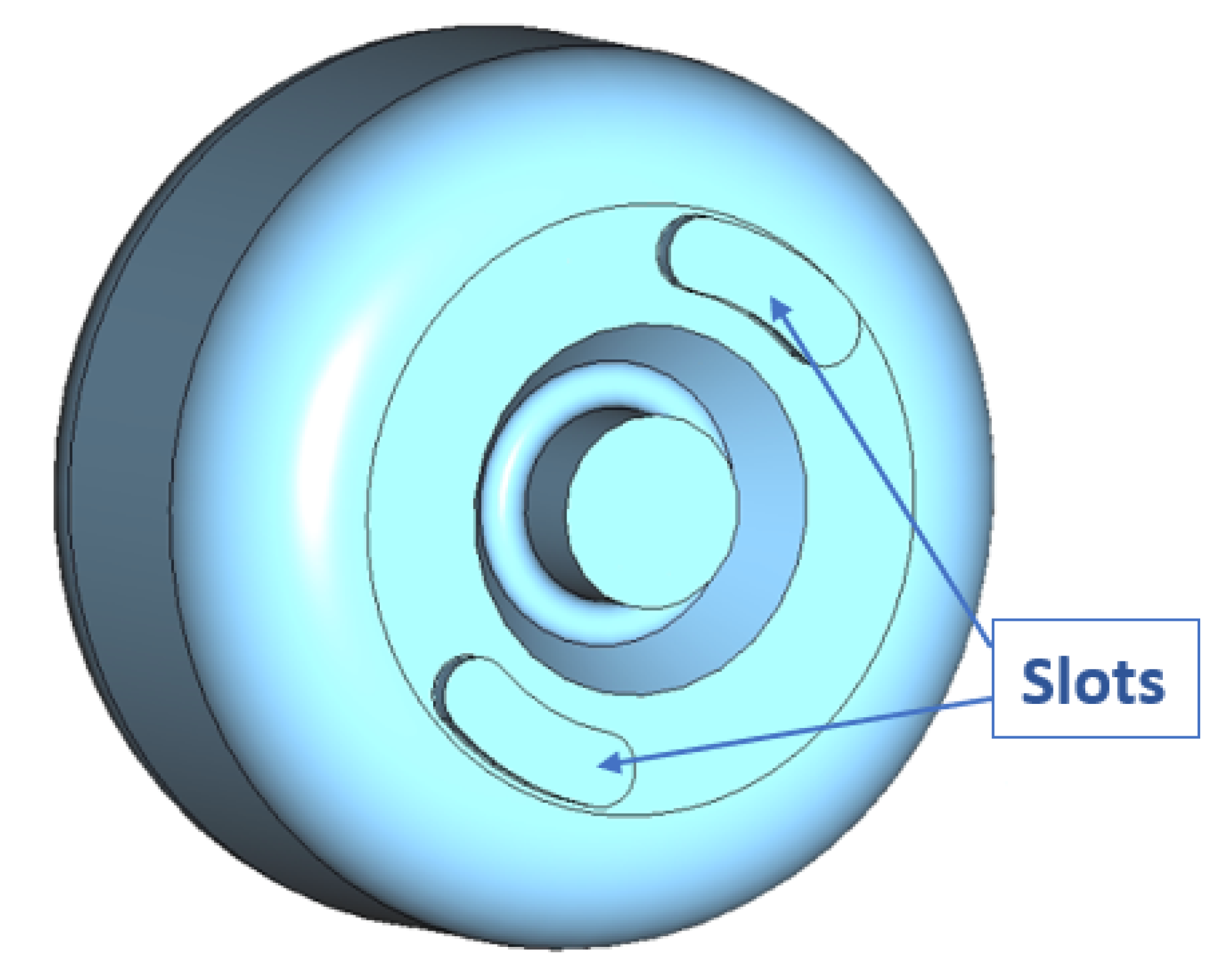
The prototype linac, shown in Figure 1, operates at 5.712 GHz in the π / 2 mode, and is a standing wave, biperiodic structure, in this configuration the accelerating cells are alternated with unexcited coupling cells. The electromagnetic field inside the prototype structure is excited by a WR187 RF waveguide. The waveguide ensures efficient and precise electromagnetic energy transfer from the power source to the linac. All cells are coupled mainly via magnetic fields through properly designed coupling holes located off-axis (see Figure 2) and secondarily via electric field through the cell’s irises. The basic component of the accelerator, which consists of an accelerating cell, two half-coupling cells, and two pairs of slots for magnetic coupling, was optimized. The length of the accelerating cell was fixed and the cell diameters were determined to obtain a resonant frequency of 5.712 GHz for each cell.
A detailed analytical and numerical study was conducted using CST Microwave Studio SUITE [16] to optimize the design of a linear accelerator. The design of the prototype made of only 5 identical cells was optimized to check the machining process, the low power fields excited in the structure and the tuning procedure. The simulations were performed with the high-frequency solver in CST. The used mesh type was the tetrahedral type, with 233,820 cells.
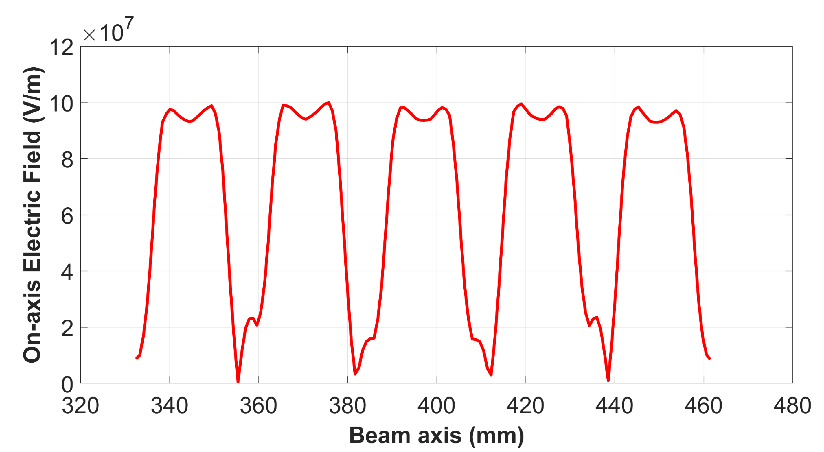
A nose-cone structure was adopted to maximize the effective shunt impedance per unit length and efficiency of acceleration. The nose cone allowed for the concentration of high electric fields in the center of the accelerating cells and optimized the structure’s efficiency by increasing the accelerating gradient. The resulting profile of the on-axis accelerating electric field is shown in Figure 3. The accelerating electric field is at its maximum on the axis, with the highest intensity occurring in the center (nose) of the accelerating cell. The electric field is null in the coupling cells.
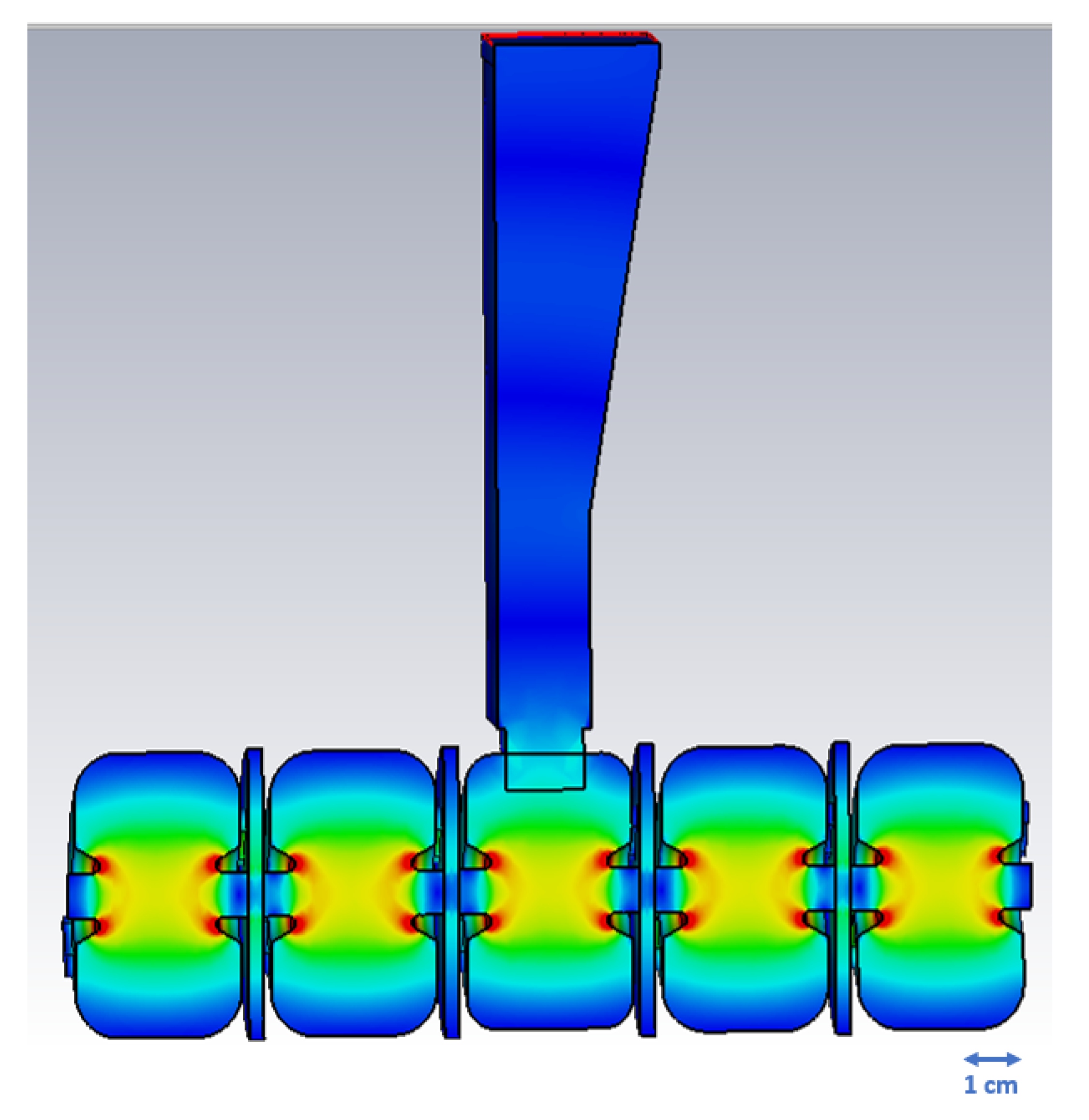
Figure 4 shows the 3D electric field contour inside the volume of the linac. Notably, the electric field is concentrated in the nose of the accelerating cell, while there is no electric field present in the coupling cells. It indicates that most energy localizes around the cell’s nose cone, which is crucial for the beam’s acceleration.
The coupler has been inserted in the central cell in order not to excite the frequency closest to the π / 2 mode. To reduce the coupler hole dimensions and, therefore, the perturbation to the electric field on the central cell, the smaller dimension of the standard C-band waveguide has been tapered. A general parameter, which describes the waveguide-to-cavity coupling strength, is the parameter β defined as [17]:
β = P e x t P c = Q 0 Q e x t
where P e x t is the RF power dissipated in the external load (connected to the cavity), P c is the RF power dissipated in the cavity lossy walls, Q 0 is the unloaded quality factor of the resonant cavity and Q e x t is the quality factor associated with the external load. In the case of a beam-loaded RF cavity, as in the present scenario, we typically design the coupling hole to have a β greater than 1 to compensate for the power P b absorbed by the electron beam according to the following formula (2) [17]:
β = 1 + P b P c
When β < 1 , it is typically said that the waveguide and cavity are under-coupled. In the case of β > 1 the waveguide and cavity is said to be over-coupled. When β = 1 the waveguide and cavity are said to be critically coupled and, as a consequence, we have that Q e x t = Q 0 and the corresponding loaded quality factor is Q L = Q 0 / 2 .
The parameter β can be directly measured from the reflection coefficient S 11 at the port of the input waveguide as the following:
S 11 = β 1 β + 1
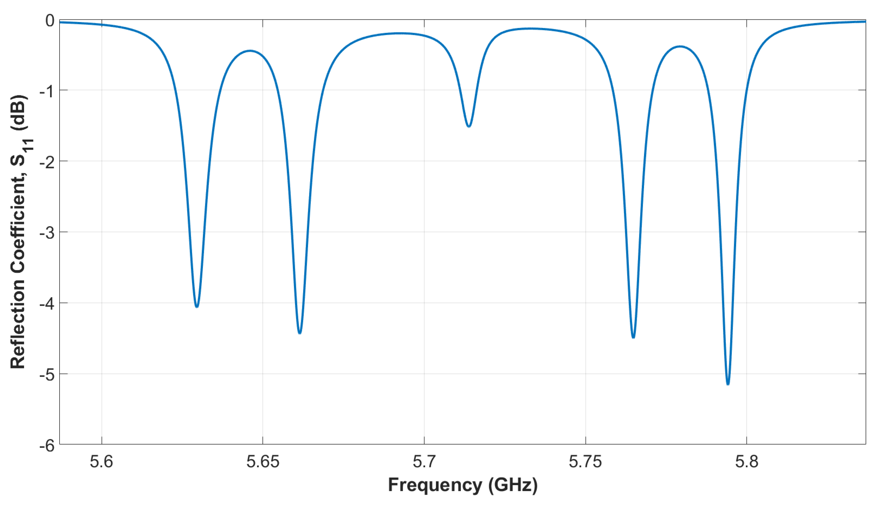
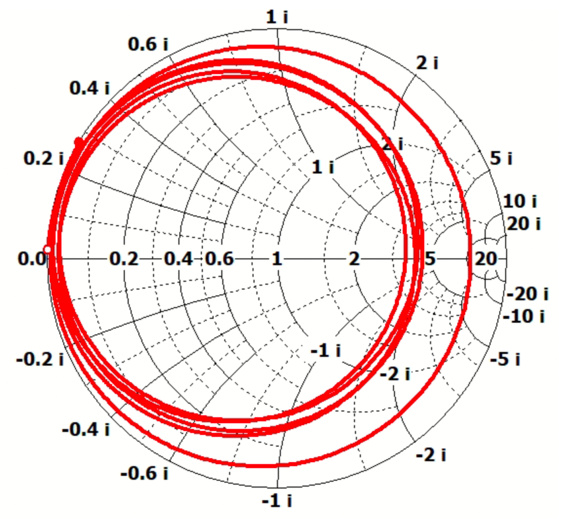
In the undercoupled case, one has that | S 11 | = ( 1 β ) ( 1 + β ) . In the overcoupled case, one has | S 11 | = ( β 1 ) ( β + 1 ) . The case β = 1 , and therefore S 11 = 0 , is called the matched case (no reflected power back to the RF source). In Figure 5, we show the reflection coefficient S 11 for the linac prototype, made of five accelerating cells, which was simulated by using the CST code with 247,011 tetrahedrons with the Frequency Domain Solver. The plot shows five minima, as expected due to the same number of accelerating cells. The accelerating mode is the central one, at the frequency of 5.7123 GHz, with a value of S 11 = 1.5 dB. The cavity is highly over-coupled, as shown from the smith charge (see Figure 6) where the circumferences include the center of the chart. It follows that the corresponding coupling parameter is equal to β = 11.6 , which is about six times larger than the one for the full linac which is β = 1.9 , as listed in Table 1. The main reason is due to the size of the hole between the waveguide and the central cell (coupler cell) that was designed for the full linac structure, made of 30 accelerating cells, as explained in the Introduction. It follows that since the RF power dissipated P c in the prototype is about one sixth of the power needed for the full accelerating structure, the parameter β results by a factor of six larger than the one of the original design. Moreover, we report other main RF parameters resulting from simulations. The unloaded quality factor, also calculated with CST, is equal to Q 0 = 11,260, which is averaged over all the cells, and the average effective shunt impedance per unit length, which is related to the RF power-to-electron beam power efficiency of the linac, equal to 115.94 MΩ/m, that is over 20% higher than typical linacs in the same frequency band. This is due to the nose-cone geometry which increases the effective shunt impedance per unit length, thus the linac efficiency, with respect to other rounded nose-less cell geometries. There are also four additional modes in the RF cavity, but they are outside the bandwidth of the RF power source, an RF pulsed magnetron that provides the RF power through a standard WR187 waveguide and into the accelerating structure through the waveguide-tapered section and the coupling hole performed on the central coupler cell. Thus, these additional modes will not interfere with the regular operation of the prototype, as they are not within the range that the RF power source can support.
The main RF parameters of the linac prototype made of five accelerating cells are listed in Table 2.

2.2. Measurements Setup

A full-scale copper prototype has been constructed, and the low-power RF characterization of the C band prototype has been performed at the Radio Frequency Laboratory for Accelerators at the Sapienza University of Rome. The prototype has been developed basically to measure and verify the resonant frequency of the operating π / 2 mode, the waveguide input port reflection coefficient S 11 coefficient and corresponding waveguide-to-linac coupling strength parameter β (discussed in the following section), to evaluate the on-axis accelerating electric field distribution of the working mode by using the bead-pull technique [18], and to characterize the other resonant modes of the RF prototype in terms of their frequencies in order to confirm that any interference is avoided. The last point is very important because of the large frequency bandwidth of the RF power source, a pulsed RF magnetron in our case, which in C-band is typically around 20 MHz.
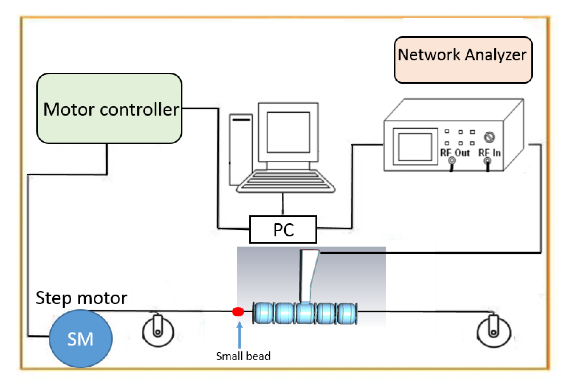
A computer was used to control the Agilent N5230A network analyzer to visualize and analyze the S 11 spectrum. The S 11 describes how much RF power is reflected from the RF structure back into the source that transmits the electromagnetic wave towards the linac prototype. Each cell is equipped with a tuner (metallic screw) used to compensate for fabrication errors and thermal distortions in the structure. The cavity’s resonant frequency can be adjusted by varying the depth of the screw inside the cavity walls. For the tuning system, we used cylindrical tuners with a radius of 2 mm for the accelerating cells and a tuner with a radius of 0.75 mm for the coupling cells.

3. Prototype RF Characterization and Results

Figure 7 shows the linac prototype on the work desk during the campaign of measurements.

3.1. Tuning Procedure

The tuning process follows the completion of the construction of the prototype linac. The tuning procedure starts by tuning each cell to the specified resonant frequency of the π / 2 mode, which is 5.712 GHz in our case. Then, the coupling cells are tuned to minimize the reflection coefficient, suppress all unwanted modes at the same frequency, and obtain symmetric peaks in the S11 spectrum. Understanding the properties of all modes of the RF structure is relevant for a complete understanding of its behavior. Indeed, the power source can excite the mode with a resonance frequency of 5.712 GHz and a bandwidth of 10 kHz; hence, other modes in the frequency spectrum can also be excited. Tuning the side mode near the π / 2 mode is necessary to minimize its impact on the operating mode. During the tuning process, the π / 2 mode is well recognized on the S11 spectrum in the Vector Network Analyzer (VNA) due to its fixed frequency when screws are adjusted. Its resonance frequency is less affected by changes in dimensions, making it easier to operate.

3.2. Resonant Frequency and Quality Factors Measurements Results

In Figure 8, we show the reflection coefficient of the linac measured at the input waveguide port before the tuning procedure. The frequency of the operating π / 2 mode results equal to 5.7135 GHz (central peak) which is only 1.2 MHz higher than the simulated one, as shown in Table 2. Nevertheless, from the figure, it is also evident that many unwanted resonant modes are present, especially the two closest to the π / 2 mode which can interfere during high-power operation since they fall in the power source frequency bandwidth. Moreover, these spurious modes affect the uniformity of the on-axis accelerating electric field, which needs to be at a maximum in each accelerating cell and null in the adjacent coupling cells. This condition is usually referred to as “field-flatness”.
In Figure 9, we show the comparison of the reflection coefficient between simulations and measurements after the final tuning of the accelerating structure. All spurious, unwanted modes are cleared out of the whole spectrum, in particular the ones nearest to the operating π / 2 mode, which resonates at f = 5.7135 GHZ. This value did not vary from the pre-tuning measurement, as expected, since the π / 2 mode is characterized by high stability in frequency. The reflection coefficient is equal to S 11 = 5 dB, versus −1 dB from simulations. It is important to point out that the waveguide and the linac are over-coupled, as designed. This results in a corresponding parameter β = 3.57 which is a factor of 3.25 lower than a simulation of β = 11.6 , as discussed previously. This discrepancy is due to the fact that the waveguide-to-linac coupling involves many physical parameters (such as a good RF contact between cells, cell-to-cell alignment, etc.) that are difficult to fulfill in an un-brazed clamped structure. As an example, for an un-brazed structure, the difference in coupling can be at least a factor of 2 which is usually always observed in measurements.
For the same reasons discussed above, the measured quality factor Q 0 has been evaluated and its maximum value is Q 0 = 7019 , which is 40% lower than the simulated one. The discrepancy between the experimental and numerical results, as reported in Table 2, is attributed to the poor RF contact between cells which is typical for a clamped structure before brazing.

3.3. Bead-Pull Measurments Setup

The on-axis accelerating electric field is measured using the bead-pull technique [18]. A small antenna is used as a probe to introduce into the prototype to excite the electromagnetic field inside the cavity without altering the field distribution. In the bead-pull technique was used a 1 mm diameter metallic sphere and a straight nylon wire were kept in place by a 75 g weight. The perturbing object was attached to a horizontal fishing line that lays in the same direction as the axis of the prototype. The measurement setup was controlled by a PC, which managed the network analyzer Agilent N5230A and the control circuit for the stepper motor, both interfaced through Labview [19]. The initial alignment was done through visual inspection, followed by measuring the zero field in the coupling cells to confirm that the perturbation object was correctly centered. In this case, no frequency shift was present. A sketch of the bead-pull measurement setup is reported in Figure 10.
The bead-pull method that we utilized exploits the Slater theorem [20]. A small perturbing object inside the cavity causes a frequency shift related to the change in electric and magnetic energy stored at the location of the object within the cavity according to the formula:
Δ f f 0 = Δ V ( s H 2 ϵ E 2 ) d τ V ( μ H 2 ϵ E 2 ) d τ = Δ U H Δ U E U
Here Δ f is the resonant frequency variation with respect to the unperturbed frequency f 0 , U the total energy stored in the cavity and U E and U H are the energy associated with the E field.

3.4. Electric Field Measurements Results

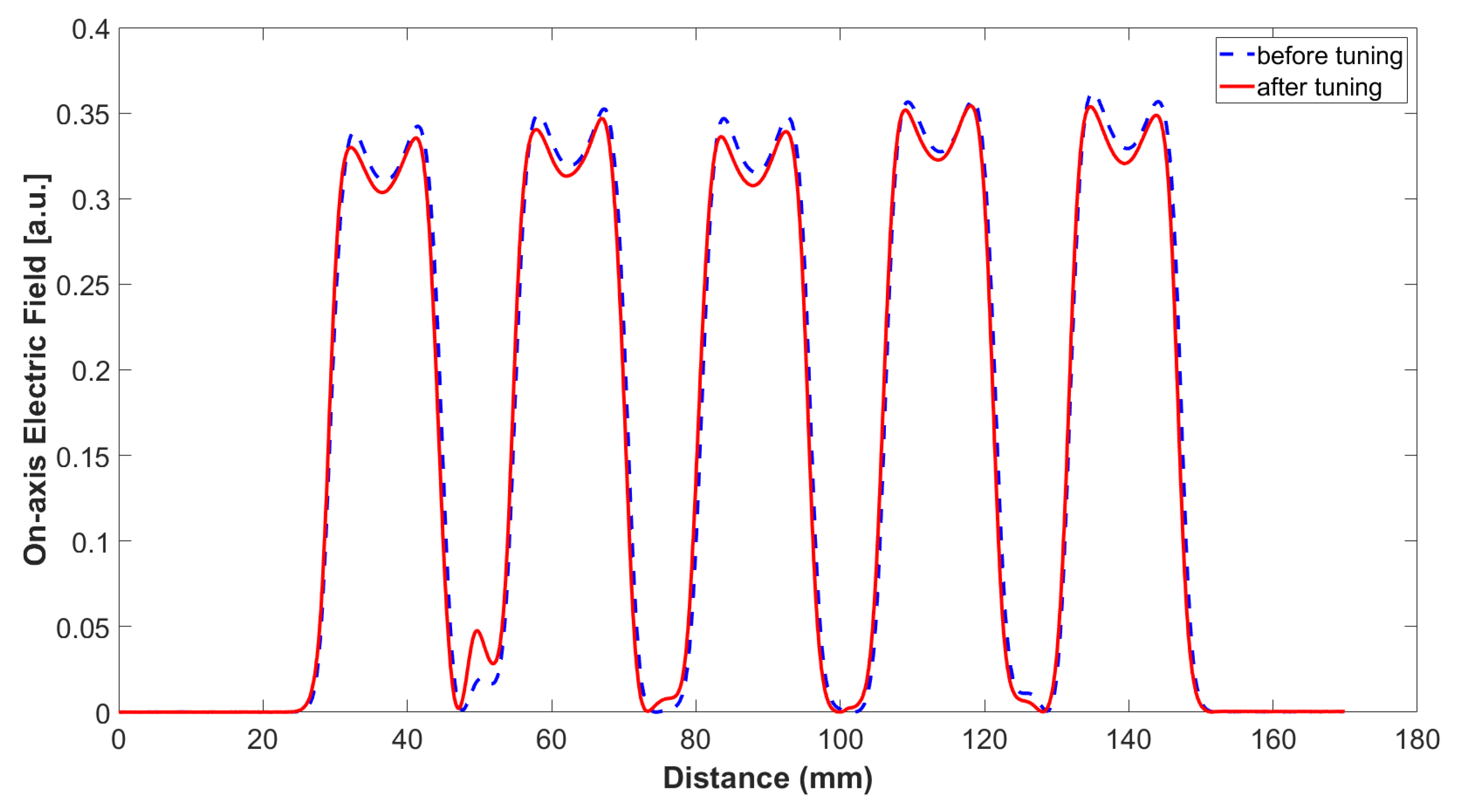
The bead-pull technique is used to measure the electric field inside the prototype before and after tuning. We report the results in Figure 11 which shows an almost equal flatness of the electric field in the five accelerating cells. The π / 2 mode, as expected, has a high electric field in the accelerating cells and no field in the coupling cells. The double peaks in the electric field profile per cell were predicted by the simulations discussed previously. This behavior is due to the nose-cone geometry of the accelerating cells which emphasizes the field values in the neighboring regions of the nose. Nevertheless, none of these double peaks affect the electron beam acceleration process.

4. Conclusions

The FLASH therapy prototype C- band linac, carried out by the SBAI Department of Sapienza University of Rome research group, has a worldwide interest. The proposal of the C-band accelerator arises from the necessity to maintain compact structures that can efficiently operate inside a hospital environment. A low-energy C-band linac (12 MeV) was designed for FLASH IOeRT therapy applications in collaboration with SIT Sordina IORT Technology Spa. In this paper, we presented the RF measurements and characterization of the prototype of the low-energy linac. We realized the RF structure design for this project using simulations code as CST. From the RF electromagnetic study, we get the best geometrical configuration for the single cells to achieve the correct resonant frequency and good flatness of the accelerating electric field. We characterized the device with a tuning procedure to properly balance the coupling among the cells and reach a good field flatness. These studies allowed us to start developing the complete linac, including the bunching section, which will be part of an IOeRT device.

Author Contributions

Methodology, L.G. and L.F. (Luigi Faillace); Software, A.M. and M.C.; Validation, L.F. (Luca Ficcadenti) and B.S.; Formal analysis, F.B.; Data curation, L.F. (Luigi Faillace); Writing—original draft, L.G., L.F. (Luigi Faillace) and G.F.; Writing—review and editing, L.G., L.F. (Luigi Faillace) and L.P.; Supervision, L.F. (Luigi Faillace), M.M. and L.P. All authors have read and agreed to the published version of the manuscript.

Funding

This research received no external funding.

Institutional Review Board Statement

Not applicable.

Informed Consent Statement

Not applicable.

Data Availability Statement

Data available on request from the authors.

Conflicts of Interest

The authors declare no conflict of interest.

References

  1. Lievens, Y.; Borras, J.; Grau, C. Provision and use of radiotherapy in Europe. Mol. Oncol. 2020, 14, 1461–1469. [Google Scholar] [CrossRef]
  2. Borras, J.; Lievens, Y.; Barton, M.; Corral, J.; Ferlay, J.; Bray, F.; Grau, C. How many new cancer patients in Europe will require radiotherapy by 2025? An ESTRO-HERO analysis. Radiother. Oncol. 2016, 119, 5–11. [Google Scholar] [CrossRef] [PubMed] [Green Version]
  3. Favaudon, V.; Caplier, L.; Monceau, V.; Pouzoulet, F.; Sayarath, M.; Fouillade, C.; Poupon, M.F.; Brito, I.; Hupé, P.; Bourhis, J.; et al. Ultrahigh dose-rate FLASH irradiation increases the differential response between normal and tumor tissue in mice. Sci. Transl. Med. 2014, 6, 245ra93. [Google Scholar] [CrossRef] [PubMed]
  4. Di Martino, F.; Del Sarto, D.; Bisogni, M.G.; Capaccioli, S.; Galante, F.; Gasperini, A.; Linsalata, S.; Mariani, G.; Pacitti, M.; Paiar, F.; et al. A new solution for UHDP and UHDR (Flash) measurements:Theory and conceptual design of ALLS chamber. Phys. Med. 2022, 102, 9–18. [Google Scholar] [CrossRef]
  5. Schuler, A.; Heinrich, S.; Fouillade, C.; Subiel, A.; De Marzi, L.; Romano, F.; Peier, P.; Trachsel, M.; Fleta, C.; Kranzer, R.; et al. The European Joint Research Project UHDpulse–Metrology for advanced radiotherapy using particle beams with ultra-high pulse dose rates. Phys. Med. 2020, 80, 134–150. [Google Scholar] [CrossRef] [PubMed]
  6. Jolly, S.; Owen, H.; Schippers, M.; Welsch, C. Technical challenges for FLASH proton therapy. Phys. Med. 2020, 78, 71–82. [Google Scholar] [CrossRef] [PubMed]
  7. Bourhis, J.; Sozzi, W.J.; Jorge, P.G.; Gaide, O.; Bailat, C.; Duclos, F.; Patin, D.; Ozsahin, M.; Bochud, F.; Germond, J.; et al. Treatment of a first patient with FLASH-radiotherapy. Radiother. Oncol. 2019, 139, 18–22. [Google Scholar] [CrossRef] [PubMed]
  8. Di Martino, F.; Barca, P.; Barone, S.; Bortoli, E.; Borgheresi, R.; Stefano, S.D.; Francesco, M.D.; Faillace, L.; Giuliano, L.; Grasso, L.; et al. FLASH radiotherapy with electrons: Issues related to the production, monitoring, and dosimetric characterization of the beam. Front. Phys. 2020, 8, 481, Erratum in Front. Phys. 2021, 8, 648. [Google Scholar] [CrossRef]
  9. Jaccard, M.; Durán, M.; Petersson, K.; Germond, J.-F.; Liger, P.; Vozenin, M.-C.; Bourhis, J.; Bochud, F.; Bailat, C. High dose-per-pulse electron beam dosimetry: Commissioning of the Oriatron eRT6 prototype linear accelerator for preclinical use. Med. Phys. 2018, 45, 863–874. [Google Scholar] [CrossRef] [PubMed]
  10. Moeckli, R.; Gonçalves, J.P.; Grilj, V.; Oesterle, R.; Cherbuin, N.; Bourhis, J.; Vozenin, M.-C.; Germond, J.-F.; Bochud, F.; Bailat, C.; et al. Commissioning of an ultra-high dose rate pulsed electron beam medical LINAC for FLASH RT preclinical animal experiments and future clinical human protocols. Med. Phys. 2021, 48, 3134–3139. [Google Scholar] [CrossRef] [PubMed]
  11. Schüler, E.; Trovati, S.; King, G.; Lartey, F.; Rafat, M.; Villegas, M.; Praxel, A.J.; Loo, B.W., Jr.; Peter, G. Maxim Experimental platform for ultra-high dose rate FLASH irradiation of small animals using a clinical linear accelerator. Int. J. Radiat. Oncol. Biol. Phys. 2017, 97, 195–203. [Google Scholar] [CrossRef] [PubMed]
  12. Lempart, M.; Blad, B.; Adrian, G.; Bäck, S.; Knöös, T.; Ceberg, C.; Petersson, K. Modifying a clinical linear accelerator for delivery of ultra-high dose rate irradiation. Radiother. Oncol. 2019, 139, 40–45. [Google Scholar] [CrossRef] [PubMed]
  13. Berne, A.; Petersson, K.; Tullis, I.; Newman, R.G.; Vojnovic, B. Monitoring electron energies during flash irradiations. Phys. Med. Biol. 2021, 4, 045015. [Google Scholar] [CrossRef] [PubMed]
  14. Faillace, L.; Barone, S.; Battistoni, G.; Di Francesco, M.; Felici, G.; Ficcadenti, L.; Franciosini, G.; Galante, F.; Giuliano, L.; Grasso, L.; et al. Compact S-band linear accelerator system for ultrafast, ultrahigh dose-rate radiotherapy. Phys. Rev. Accel. Beams 2021, 24, 050102. [Google Scholar] [CrossRef]
  15. Giuliano, L.; Franciosini, G.; Palumbo, L.; Aggar, L.; Dutreix, M.; Faillace, L.; Favaudon, V.; Felici, G.; Galante, F.; Mostacci, A.; et al. Characterization of Ultra-High-Dose Rate Electron Beams with ElectronFlash Linac. Appl. Sci. 2023, 13, 631. [Google Scholar] [CrossRef]
  16. CST Microwave Studio Suite. Available online: https://www.3ds.com/products-services/simulia/products/cst-studio-suite/ (accessed on 15 December 2022).
  17. Wangler, T.P. RF Linear Accelerators; John Wiley & Sons: New York, NY, USA, 2008; p. 045015. [Google Scholar]
  18. Ginzton, E.L. Microwave Measurements; McGraw-Hill: New York, NY, USA, 1958. [Google Scholar]
  19. Kalkman, C.J. LabVIEW: A software system for data acquisition, data analysis, and instrument control. J. Clin. Monit. 1995, 11, 51–58. [Google Scholar] [CrossRef] [PubMed]
  20. Maier, L.C., Jr.; Slater, J.C. Field strength measurements in resonant cavities. J. Appl. Phys. 1952, 23, 68–77. [Google Scholar] [CrossRef] [Green Version]
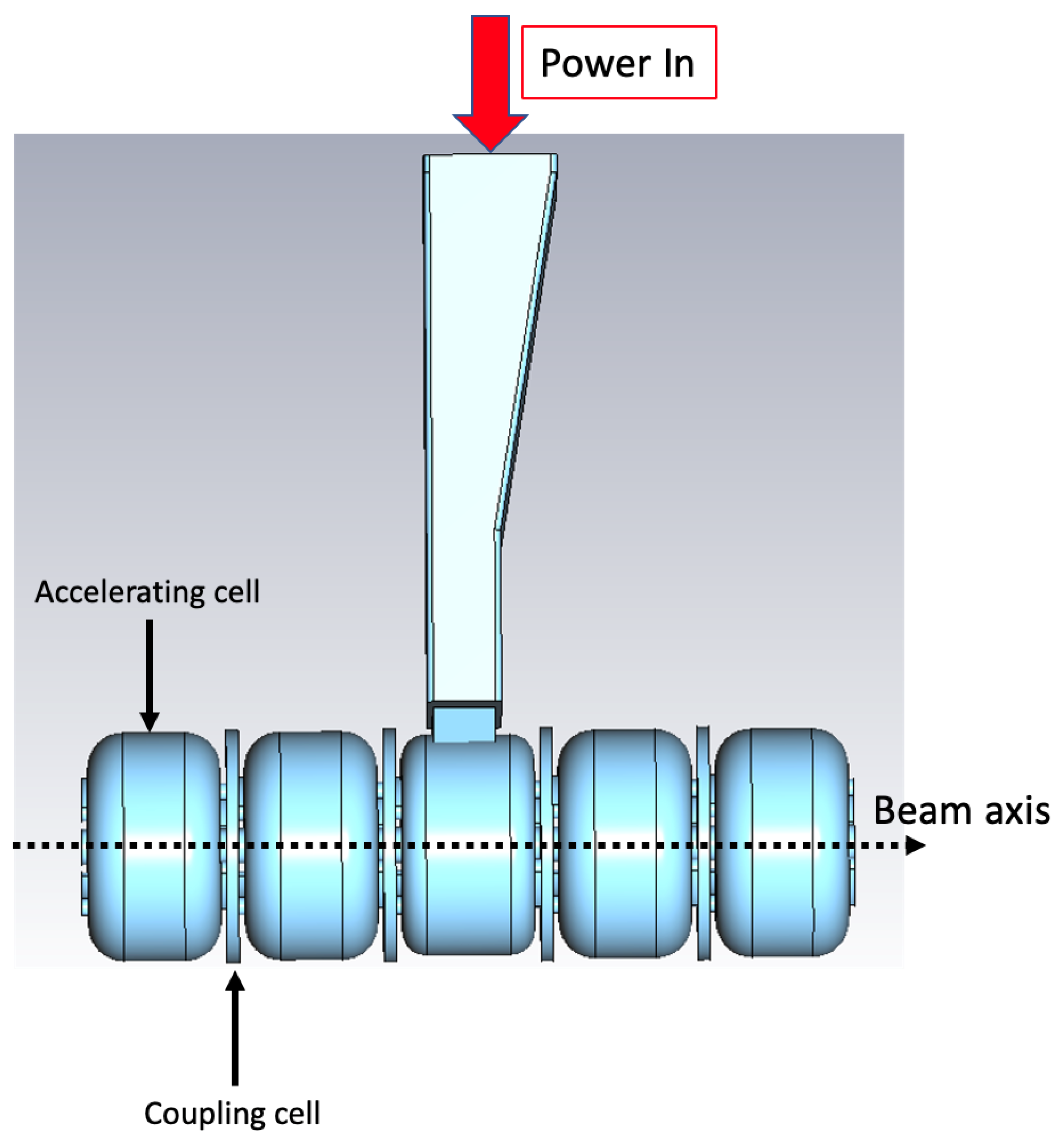
Figure 1. 3D Prototype on CST for the electromagnetic design.
Instruments 07 00010 g001
Figure 2. Slots located off axis for the electromagnetic coupling.
Instruments 07 00010 g002
Figure 3. On-axis Accelerating electric field profile of the operating mode simulated with CST.
Instruments 07 00010 g003
Figure 4. 3D electric field contour inside the volume of the linac.
Instruments 07 00010 g004
Figure 5. The reflection coefficient S11 in decibels (dB), simulated using CST Studio Suite code in Frequency Domain Solver.
Instruments 07 00010 g005
Figure 6. Smith Chart of S11.
Instruments 07 00010 g006
Figure 7. C-band linac prototype at Sapienza Accelerators Laboratory, on the work desk.
Instruments 07 00010 g007
Figure 8. Reflection coefficient S11 in dB before the tuning process.
Instruments 07 00010 g008
Figure 9. Comparison of the Reflection coefficient S11 in dB after tuning process (in blue) and from simulations (in red).
Instruments 07 00010 g009
Figure 10. Sketch of the bead-pull measurement setup.
Instruments 07 00010 g010
Figure 11. On-axis electric field from low-power RF tests before tunign (in blue) and after tuning process (in red).
Instruments 07 00010 g011
Table 1. C-band linac parameters for IOeRT FLASH irradiations.
ParameterValue
Beam final energy9–12 MeV
Frequency5.712 GHz
Pulse width4 µs
Repetition frequency100 Hz
Peak current50–120 mA
Instantaneous dose rate> 10 6
Dose per pulse>20 Gy in ø10 cm
Quality factor11,260
Eff. Shunt Impedance115.94 MΩ/m
Waveguide-to-linac coupling β 1.9
Power Input2.5 MW
Table 2. Cavity RF parameters.
ParameterValue
Frequency5.7123 GHz
Number of Accelerating Cells5
Number of Coupling Cells4
Prototype linac length12.90 cm
Quality factor Q 0 11,260
Shunt impedance r115.94 MΩ/m
Disclaimer/Publisher’s Note: The statements, opinions and data contained in all publications are solely those of the individual author(s) and contributor(s) and not of MDPI and/or the editor(s). MDPI and/or the editor(s) disclaim responsibility for any injury to people or property resulting from any ideas, methods, instructions or products referred to in the content.